ZXZ20数字全景钻孔成像装置技术说明(REV1.3)
- 格式:doc
- 大小:3.84 MB
- 文档页数:7

HX-JD-01B|02B|03B|01C高清智能钻孔电视成像仪系列产品用户手册湖南奥成科技有限公司产品HX-JD-01B|02B|03B|01C智能钻孔电视成像仪版本: V4.1作者:奥成科技研发部湖南奥成科技有限公司二0一七年七月产品升级说明1、探头密封性:标准型探头耐压4MPa(测井400米),加强型探头最深测井1200米。
2、电缆及绞车:400米电缆及绞车重量20kg左右,120米微型绞车重量10kg左右。
3、配套软件升级至1.3版本,汲取市场上各类钻孔电视优点。
4、浑水孔改进:其一:提供直径可变可拆卸的浑水孔排水玻璃罩,其二:我们同化工厂商联合研制浑水净化剂,浑水孔只需30分钟左右即可澄清,净化速度比传统明矾净水快100倍左右,且无絮状物出现,且对水源无任何污染。
5、适合孔径30mm-300mm水平、倾斜、垂直、天顶孔。
6、存储数据达32G,存放3000米以上视频数据。
7、绞车可装卸,提供手动、自动一体滑轮8、提供内置电池。
目 录第一章 概述 (5)1.1前言 (5)1.2 仪器配置 (5)1.3 系统技术指标 (6)1.3.1 软件技术指标 (6)1.3.2 硬件技术指标 (7)1.3.3 机械设计指标 (8)第二章 仪器组成与维护 (9)2.1 仪器组成 (9)2.1.1控制系统组成 (10)2.1.2卷扬系统组成 (12)2.1.3 数据采集处理系统组成 (13)2.2 仪器保养与维护 (14)第三章 仪器使用 (15)3.1 设备连接 (15)3.2 校准 (16)3.3 软件使用 (17)3.3.1 参数设置 (18)3.3.2 数据采集与传输 (21)3.3.3 仪器系统软件管理 (22)第四章 数据处理软件使用 (23)4.1 数据分析分析软件安装 (23)4.2 数据导入 (23)4.2.1 导入图像数据 (23)4.2.2 导入视频数据 (25)4.3 数据查看与分析 (26)4.4 数据合并 (27)4.5 数据报表输出 (28)第五章 系统更新与维护 (34)第六章 联系我们 (35)第一章 概述1.1前言钻孔成像设备能以照相胶片或视频图像的方式直接提供孔壁的图像。

Installation Guide forRoboSHOT20UHDHigh Performance,Ultra High Definition PTZ CameraDocument342-1193Rev.CJuly2016ContentsOverview1 What's in this Guide1 Camera Features1 Unpacking the Camera2A Quick Look at the Camera3Front of the Camera3 Connector Panel4 Switch Settings4 Video Resolution5 Camera Settings6 Installation7 Before You Install the Camera7 Don’t Void Your Warranty!7 Cabling Notes7 Installing the Wall Mount8 About Ceiling-Mounted Cameras8 Basic Connection Diagram8 Installing the Camera9 Powering Up the Camera10 Operation,Storage,and Care10 Next Steps10 Compliance Statements and Declarations of Conformity11 FCC Part15Compliance11 ICES-003Compliance11 European Compliance12 Warranty Information13 Index14OverviewThis guide covers the RoboSHOT™20UHD high performance PTZ camera:n RoboSHOT20UHD(silver and black),North America–999-9950-000n RoboSHOT20UHD(white),North America–999-9950-000Wn RoboSHOT20UHD(silver and black),International–999-9950-001n RoboSHOT20UHD(white),International–999-9950-001WWhat's in this GuideThis guide covers:n Unpacking the cameran Tips for a successful installationn Instructions for installing the camera mountn Information on connecting and mounting the cameran Camera power-onComplete product information is available in the Integrator's Complete Guide to RoboSHOT20UHD Ultra-High Definition PTZ Cameras.Camera Featuresn Back-illuminated9.03Megapixel,ultra high definition1/2.3-type sensor delivers native2160p/30(3840x2160)videon12X optical zoom and1.67X digital zoom;effective20Xzoom range;horizontal field of view74°(wide)to4.8°(tele)at20Xn Imaging and performance comparable to3-chip camerasn Precise pan and tilt movements from120°/s down to0.35°/sn Tri-Synchronous Motion™simultaneous3-axispan/tilt/zoom movement between presetsn Simultaneous HDMI®,HDBaseT™,3Gb/s HD-SDI and IPstreaming outputsn Presenter-friendly IR remote controln Full administrative control from your browser via webinterfacen Integration-ready Telnet or serial RS-232controln Smooth,silent direct-drive motorsUnpacking the CameraMake sure you received all the items you expected.CautionAlways support the camera's base when picking it up.Lifting the camera by its head or mountingarm will damage it.North AmericaPart number999-9950-000,RoboSHOT20UHD in silver and blackPart number999-9950-000W,RoboSHOT20UHD inwhiten Vaddio IR Remote Commandern12VDC,3.0A switching power supplyn AC cord set for North American Thin Profile Wall Mount with mounting hardwaren EZCamera RS-232control adaptern Quick Start GuideInternationalPart number999-9950-001,RoboSHOT20UHD in silver and blackPart number999-9950-001W,RoboSHOT20UHD inwhiten Vaddio IR Remote Commandern12VDC,3.0A switching power supplyn AC cord sets for UK and Europen Thin Profile Wall Mount with mounting hardwaren EZCamera RS-232control adaptern Quick Start GuideA Quick Look at the CameraThis section covers the physical features of the RoboSHOT20UHD.Front of the Cameran Camera and Zoom Lens:Horizontal field of view up to74°.12X optical zoom combines with1.67X digital zoom to deliver an effective20X zoom range;4.8°field of view at20X.n Dual-arm mount provides superior stability.n IR Sensors:Sensors in the front of the camera base receive signals from the IR Remote Commander.Make sure there are no obstructions directly in front of the camera base.n Status indicator:The multi-colored LED indicates the camera's current state.o Purple–Boot-up and Standby modes.o Blue–Normal operation and is a power on,ready condition.o Blinking blue–The camera has received IR from the remote or other IR source.o Red–Tally function;shows that the camera is on-air.o Blinking red–Fault condition.o Yellow–Firmware update is in progress.CautionDo not remove power or reset the camera while the indicator is yellow,showing a firmware update in progress.Interrupting a firmware update can make the camera unusable.Connector PanelFrom left to right:n12VDC,3.0A connector–EIA-J04connector for the power supply shipped with the camera,if not using a OneLINK extension systemn OneLINK HDBaseT connector–Connect to the network(H.264IP streaming,web interface or Telnet control,and PoE++power)or a OneLINK extension system(video,power and control up to328ft/100m)n HDMI connector–HDMI video outputn HD-SDI connector–HD-SDI video outputn RS-232port–Connect to a camera controller to manage the camera using a modified VISCA protocol n HD video select switch–Select the appropriate output resolution for local outputsn DIP switches–Set IR frequency,IR on/off,image flip(camera is invertible),and baud rateSwitch SettingsRoboSHOT cameras use a rotary switch to set the video resolution and a set of DIP switches that determine certain camera functions.A label on the bottom of the camera provides a quick reference for setting the switches.NoteSet the switches appropriately before mounting the camera.Video ResolutionSet the desired available output resolution for the camera with the rotary switch.Switch positions A through F are not used.NoteThe maximum resolution for the HD-SDI output and the IP stream is1080p.Camera SettingsUse the DIP switches to set other camera behaviors.NoteWhen the camera is right side up,switches are in their default positions when they are up.IR Frequency Selection:The IR Remote Commander can control up to three cameras in the same room independently,if they are configured with different IR e switches1and2to select the frequency to identify the camera as camera1,2,or3;then use the Camera Select buttons at the top of the remote to select the camera you want to control.IR:Leave switch3in the default UP position if the IR remote will be used.Inverted operation:If mounting the camera upside-down,set switch4to the DOWN position:IMAGE FLIP ON.Baud Rate: Set the baud rate for RS-232communication using switch5.Most applications use9600bps (switch6UP),which is recommended when using long cable e the38,400bps setting(switch6 DOWN)for short control lines only.Switch6is not currently used.Pro TipDouble-check switch settings before you mount the camera.InstallationThis section coversn Siting the cameran Installing the mountn Connecting the cameran Installing the cameraBefore You Install the Cameran Choose a camera mounting location that will optimize camera performance.Consider camera viewing angles,lighting conditions,line-of-sight obstructions,and in-wall obstructions where the camera is to be mounted.n If the IR Remote Commander will be used,ensure that nothing blocks the IR lens in the camera's base. n Ensure that the camera body can move freely and point away from the ceiling and lights.n Follow the installation instructions included with the camera mount.Don’t Void Your Warranty!CautionThis product is for indoor use.Do not install it outdoors or in a humid environment without the appropriate protective enclosure.Do not allow it to come into contact with any liquid.Use only the power supply included with this ing a different one will void the warranty,and could create unsafe operating conditions or damage the product.Do not install or operate this product if it has been dropped,damaged,or exposed to liquids.If any of these things happen,return it to Vaddio for safety and functional testing.DomeVIEW enclosures are available to allow outdoor installation of RoboSHOT cameras.Learn more at /products.Cabling NotesUse Cat-5e or better cable and standard RJ-45connectors(568B termination).We recommend using high-quality connectors and a high-quality crimping tool.CautionCheck Cat-5cables for continuity before using ing the wrong pin-out may damage the camera system and void the warranty.NoteDo not use pass-through RJ-45connectors.These can cause intermittent connectionsand degraded signal quality,resulting in problems that may be hard to estandard RJ-45connectors.Pro TipTo prevent tragic mishaps,label both ends of every cable.Installing the Wall MountAll RoboSHOT cameras include a Thin Profile Wall Mount.Other mounting options are available as well. Contact us if you don't have the camera mount you need.You can install the camera wall mount to a2-gang wall box or directly to the drywall.n If you mount it to drywall,use the wall anchors provided with the wall mount.n If you mount it to a wall box,use the cover plate screws supplied with the wall box.About Ceiling-Mounted CamerasIf you use an inverted mount,set the camera's Image Flip DIP switch ON for inverted operation.See Camera Settings for more information.Basic Connection DiagramThe Quick-Start Guide for RoboSHOT20UHD provides additional information.NoteThe OneLINK™interface is not required.Installing the CameraCautionBefore you start,be sure you can identify all cables correctly.Connecting a cable to the wrong port can result in equipment damage.CautionCheck Cat-5cables for continuity before using ing the wrong pin-out may damage the camera system and void the warranty.1.Route the cables to the camera location.2.Route the cables through the mount,and install the mount on the wall or attach it to the wall box.Leavethe screws loose enough to adjust the position of the mount.3.Level the mount and tighten the mounting screws.4.Check the level again.5.Connect the cables to the camera.Caution:Use the power supply shipped with the ing a different power supply may create an unsafe operating condition or damage the camera,and will void the warranty.6.Ensure that the video resolution switch and the DIP switches are set appropriately.See SwitchSettings.7.Place the camera on the mount.8.Attach the camera to the mount using the¼”-20x.375mounting screw supplied with the camera.Image for illustration only;not to scale.Camera and mount details may differ.Powering Up the CameraConnect camera power.The camera will wake up and initialize.This will take a few seconds. When the camera is initialized and ready,its front indicator is blue.At this point,it is ready to accept control information.When powering up,the RoboSHOT20UHD camera executes a different sequence of movements than other Vaddio PTZ cameras.NoteWait until the camera finishes initializing before trying to control it using the IR remote or other command input.Operation,Storage,and CareFor smears or smudges on the product,wipe with a clean,soft e a lens cleaner on the lens.Do not use any abrasive chemicals.Keep this device away from food and liquids.Do not operate or store the device under any of the following conditions:n Temperatures above40°C(104°F)or below0°C(32°F)n High humidity,condensing or wet environmentsn Inclement weathern Severe vibrationn Between converging tectonic platesn Dry environments with an excess of static dischargeDo not attempt to take this product apart.There are no user-serviceable components inside.Next StepsThe camera is now ready to configure and use.This information is available in the Configuration and Administration Guide for RoboSHOT20UHD Ultra High Definition PTZ Cameras.It is also included in the Integrator's Complete Guide to RoboSHOT20UHD Ultra High Definition PTZ Cameras.Compliance Statements and Declarations of ConformityCompliance testing was performed to the following regulations:FCC Part15(15.107,15.109),Subpart B Class AICES-003,Issue54: 2012Class AEMC Directive2004/108/EC Class AEN55022:December2010Class AEN55024:November2010Class AKN222008(CISPR22:2006)Class AKN242008(CISPR24:1997+A1:2000+A2:2002)Class AIEC60950-1:2005(2nd Edition);Am1:2009+Am2:2013SafetyEN60950-1:2006+A11:2009+A1:2010+A12:2011+A2:2013SafetyFCC Part15ComplianceThis equipment has been tested and found to comply with the limits for a Class A digital device,pursuant to Part15,Subpart B,of the FCC Rules. These limits are designed to provide reasonable protection against harmful interference when the equipment is operated in a commercial environment.This equipment generates,uses,and can radiate radio frequency energy and,if not installed and used in accordance with the instruction manual,may cause harmful interference to radio communications.Operation of this equipment in a residential area is likely to cause harmful interference in which case the user will be required to correct the interference at his/her own expense.Operation is subject to the following two conditions:(1)This device may not causeinterference,and(2)This device must accept any interference including interference thatmay cause undesired operation of the device.Changes or modifications not expressly approved by Vaddio can affect emissioncompliance and could void the user’s authority to operate this equipment.ICES-003ComplianceThis digital apparatus does not exceed the Class A limits for radio noise emissions from digital apparatus set out in the Radio Interference Regulations of the Canadian Department of Communications.Le présent appareil numérique n’emet pas de bruits radioélectriquesdépassant les limites applicables aux appareils numeriques de la classe Apréscrites dans le Règlement sur le brouillage radioélectriqueédicte par le ministère des Communications du Canada.European ComplianceThis product has been evaluated for electromagnetic compatibility under the EMC Directive for Emissions and Immunity and meets the requirements for a Class A digital device. In a domestic environment this product may cause radio interference in which case the user may be required to take adequate measures.Standard(s)To Which Conformity Is Declared:EMC Directive2004/108/ECEN55022:December2010Conducted and Radiated Emissions EN55024:November2010ImmunityEN61000-4-2:1995+Amendments A1:1998+A2:2001Electrostatic DischargeEN61000-4-3:2006+A1:2008Radiated ImmunityEN61000-4-4:2004+Corrigendum2006Electrical Fast TransientsEN61000-4-5:2006Surge ImmunityEN61000-4-6:2009Conducted ImmunityEN61000-4-8:2010Power Frequency Magnetic FieldEN61000-4-11:2004Voltage Dips,Interrupts and FluctuationsKN222008(CISPR22:2006)Conducted and Radiated Emissions KN242008(CISPR24:1997+A1:2000+A2:2002)IT Immunity CharacteristicsEN61000-4-2Electrostatic DischargeEN61000-4-3Radiated ImmunityEN61000-4-4Electrical Fast TransientsEN61000-4-5Surge ImmunityEN61000-4-6Conducted ImmunityEN61000-4-8Power Frequency Magnetic FieldEN61000-4-11Voltage Dips,Interrupts and FluctuationsIEC60950-1:2005(2nd Edition);Am1:2009+Am2:2013Safety EN60950-1:2006+A11:2009+A1:2010+A12:2011+A2:2013SafetyWarranty InformationSee Vaddio Warranty,Service and Return Policies posted on for complete details. Hardware*warranty:Two(2)year limited warranty on all parts and labor for Vaddio manufactured products. Vaddio warrants its manufactured products against defects in materials and workmanship for a period of two years from the day of purchase,to the original purchaser,if Vaddio receives notice of such defects during the warranty. Vaddio,at its option,will repair or replace products that prove to be defective. Vaddio manufactures its hardware products from parts and components that are new or equivalent to new in accordance with industry standard practices.Exclusions: The above warranty shall not apply to defects resulting from improper or inadequate maintenance by the customer,customers applied software or interfacing,unauthorized modifications or misuse,mishandling,operation outside the normal environmental specifications for the product,use of the incorrect power supply,modified power supply or improper site operation and maintenance. OEM and special order products manufactured by other companies are excluded and are covered by the manufacturer’s warranty.Vaddio Customer Service: Vaddio will test,repair,or replace the product or products without charge if the unit is under warranty. If the product is out of warranty,Vaddio will test then repair the product or products. The cost of parts and labor charge will be estimated by a technician and confirmed by the customer prior to repair. All components must be returned for testing as a complete unit. Vaddio will not accept responsibility for shipment after it has left the premises.Vaddio Technical Support: Vaddio technicians will determine and discuss with the customer the criteria for repair costs and/or replacement.Vaddio Technical Support can be contacted by email at******************or by phone at one of the phone numbers listed on .Return Material Authorization(RMA)number: Before returning a product for repair or replacement request an RMA from Vaddio’s technical support. Provide the technician with a return phone number,e-mail address,shipping address,product serial numbers and original purchase order number. Describe the reason for repairs or returns as well as the date of purchase.See the General RMA Terms and Procedures section for more information.RMAs are valid for30days and will be issued to Vaddio dealers only. End users must return products through Vaddio dealers.Include the assigned RMA number in all correspondence with Vaddio. Write the assigned RMA number clearly on the shipping label of the box when returning the product. All products returned for credit are subject to a restocking charge without exception. Special order product are not returnable.Voided varranty: The warranty does not apply if the original serial number has been removed or if the product has been disassembled or damaged through misuse,accident,modifications,use of incorrect power supply,use of a modified power supply or unauthorized repair.Shipping and handling: Vaddio will not pay for inbound shipping transportation or insurance charges or accept any responsibility for laws and ordinances from inbound transit. Vaddio will pay for outbound shipping,transportation,and insurance charges for all items under warranty but will not assume responsibility for loss and/or damage by the outbound freight carrier. If the return shipment appears damaged,retain the original boxes and packing material for inspection by the carrier. Contact your carrier immediately.Products not under warranty:Payment arrangements are required before outbound shipment for all out of warranty products.IndexAanatomy of the camera3-4Bbaud rate setting6behavior on power-up10Ccable connectors4,7camera ID setting(DIP switch)6camera mount,installing8camera select See also camera ID setting (DIP switch)ceiling-mounted cameras8cheat sheet3indicator light3cleaning10colors of the status light3connection example8connector identification4Ddamage,preventing7Iimage flip setting(DIP switch)6indicator light3installation,typical8inverted installation8IR on/off(DIP switch)6Llocations of connectors4Mmounting cameras7-9OOneLINK system8operating environment10Ppacking lists2power on/power off10product returns and repairs13Qquick reference3indicator light3Rresolution4switch setting4RJ-45connectors7RS-232serial connection4Sshelf-mounted cameras9shelf,camera mount8status light,meanings of colors3 storage environment10switch settings6,8baud rate(DIP switch)6camera ID(DIP switch)6image flip(DIP switch)6,8IR6switch,video resolution4Ttemperature,operating and storage10 typical installation9Vvideo resolution setting4Wwarranty7,13RoboSHOT™,OneLINK™,EZCamera™,and IR Remote Commander™are trademarks of Vaddio.The terms HDMI and HDMI High-Definition Multimedia Interface,and the HDMI Logo are trademarks or registered trademarks of HDMI Licensing LLC in the United States and other countries.HDBaseT™and the HDBaseT Alliance logo are trademarks of the HDBaseT Alliance.Exmor®is a trademark of Sony Corporation.All other trademarks in this document are the property of their respective owners. Copyright©2016Vaddio.All rights reserved.Vaddio131Cheshire Ln.,Suite500Minnetonka,MN55305。

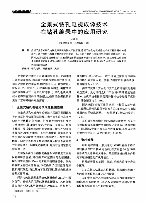
ZXZ20(A)型矿用钻孔成像仪的应用与分析梁国华【摘要】为准确掌握工作面顶板岩性资料,一矿采用ZXZ20(A)型矿用钻孔成像仪进行顶板岩性分析,该成像仪能实现对钻孔的窥视,通过视频和图片可以直观看到顶板岩性及完整情况,软件分析后提供柱状资料,为巷道顶板管理和支护设计提供了依据.【期刊名称】《山东煤炭科技》【年(卷),期】2018(000)010【总页数】3页(P150-151,154)【关键词】钻孔成像仪;窥视;顶板;岩性分析【作者】梁国华【作者单位】阳泉煤业(集团)有限责任公司一矿,山西阳泉 045008【正文语种】中文【中图分类】TD313;P634.4阳煤集团一矿位于沁水煤田北端,太行复背斜西翼,矿区位于山西省阳泉市西北部和盂县东南部,东南距阳泉市10 km,地跨阳泉和盂县两市县。
一矿井田位于矿区大单斜的西北部,其构造形态基本上呈一单斜状,其走向为北西,倾向为南西。
沿单斜走向和倾向均发育有次一级的较平缓的褶皱群和层间断裂构造,局部地段发育有陡倾挠曲,本井田陷落柱较发育,大部为砂岩及泥岩。
一矿是阳煤集团的主体矿井,多年来产量保持在700万t以上,进尺完成30000 m以上。
随着一矿和有关科研院所的合作,在全矿推广了高预应力锚网支护技术。
但多年的顶板岩性探测手段单一,无法及时为工作面提供顶板资料,造成在巷道顶板管理和支护设计上还存在问题。
为在巷道施工和支护设计时,提供准确地质资料,对顶板具体岩性结构进行分析和参考,结合推广高预应力支护和顶板岩性探测的实际情况,一矿试验推广了山东尤洛卡矿业安全工程股份有限公司ZXZ20(A)型矿用钻孔成像仪,取得了很好的效果,为顶板管理和支护设计提供了依据。
1 钻孔成像仪介绍1.1 钻孔成像仪构成钻孔成像仪主要由主机、探头、深度编码器及若干附件(电缆绞车、视频电缆、推送杆)组成。
井下录制的钻孔探测数据,在地面上可以使用USB数据传输口传输到电脑上,可用于做进一步观测、分析和研究。

ZXZ20数字全景钻孔成像装置技术说明尤洛卡矿业安全工程股份有限公司一、概述ZXZ20数字全景钻孔成像装置主要用于较大直径地质钻孔的数字化成像探测,可以连续记录钻孔的构造影像。
自动准确记录测量深度,通过计算机软件处理能准确地获得钻孔内结构面产状、裂隙深度、宽度等参数,可展开形成经无缝拼接处理后的平面展开图,也可生成钻孔孔壁的三维柱状图。
该系统可用于煤矿岩层分类、煤层储量统计、工作面超前构造探测、水灾害探测等探测领域,是工作面顶板灾害和水灾害防治的有效探测工具。
图1 ZXZ20数字全景钻孔成像装置二、系统主要技术特点1. 全景成像(360°)式观测探头,可形成孔壁360°平面展开图和虚拟三维钻孔岩芯图;2. 图像捕获和分析软件,实时监视与快速分析,可定量获得孔内裂隙产状和隙宽;3. 适用于各种方向的钻孔,如垂直、倾斜、水平等各种方位的钻孔;4. 适用孔径范围大,可勘测从Φ28mm到Φ45mm(配备居中器)的各种类型钻孔;5. 深度测量精度高,深度显示分辨率1cm;6. 防爆型式:矿用本质安全型,防爆标志“ExibI”。
三、装置组成及结构系统主要包括:ZXZ20-Z矿用钻孔成像装置主机、ZXZ20-T矿用钻孔成像装置探头、ZXZ20-S矿用钻孔成像装置深度编码器、推杆、图像捕获与分析软件。
四、ZXZ-VIEWER图像捕获分析软件1. 软件功能描述图像文件播放、编辑、管理功能;展开生成完整钻孔(360°)孔壁的二维图像;可对展开的二维图像进行人工修正和处理;可以对岩性、裂隙宽度、产状等进行计算和描述;可以生成钻孔孔壁的三维柱状图;钻孔图像资料管理,分析结果可形成报表。
2. 软件界面图2 实时图像捕图3 分析软件界面图4 全景图片浏览图5 二维展开界面五、装置主要综合技术指标图7:报表输出图6:孔壁三维柱状图生成界面1. 综合技术指标六、配置明细表。
BOSBO博视宝科幻真3D BOSBO博视宝X20科幻真3D产品说明书目录目录1.360主机产品参数 (3)2.产品视图 (4)3.产品引脚功能定义 (17)4.产品安装指南 (20)安装前准备工具: (20)安装步骤: (20)通用摄像头安装: (20)主机安装: (20)5.产品接线指南 (21)◆主机线束插头定义 (21)◆3种信号输出接线实拍 (24)6.产品拼接指南 (26)◆铺布 (26)◆标定 (27)◆铺标定失败原因 (30)7.旋钮激活与使用 (32)◆遥控器激活 (32)◆遥控器使用 (33)1.360主机产品参数表 1.1超级真3D技术参数板框尺寸ARM Cortex-A7额定电压DC12V电压范围DC7--28V额定电流≤0.8A@12V额定最大工作电流≤1.0A静态电流:≤0.5mA绝缘阻抗≥100MΩ工作温度-20℃~+70℃存储温度-40℃~+85℃视频输入AHD(1280x720@25fps)/CVBS视频输出CVBS/AHD/VGA三选一2.产品视图图13D全景视图模式图2前视超广角全屏模式图32D全景+前视带轨迹模式图4前视放大模式图52D大环视模式图6后视超广角全屏模式图72D全景+后视畸变校正加轨迹模式图8后视放大模式图92D全景+窄道模式图102D过窄道模式图112D左视图带畸变校正图122D右视图带畸变校正图13进入录像模式图14进入设置模式图15功能菜单模式图16个性化设置模式图17行车记录仪设置模式图18格式化录像磁盘模式图19停车监控设置模式图20系统设置模式图21标定距离设置模式图22系统时间设置模式图23车型设置模式图24显示设置模式图25配置参数导入或导出模式图26版本查看模式3.产品引脚功能定义科幻真3D接口JP5引脚示意图如图28所示:图28JP5引脚示意图表2JP5引脚定义说明科幻真3D接口JP4引脚示意图如图29所示:图29JP4引脚示意图表3JP4引脚定义说明引脚名称序号输入/输出引脚定义说明CAM_F_GND1输入前视摄像头输入CAM_F_VIDEO3CAM_F_VCC5CAM_R_GND2输入右视摄像头输入CAM_R_VIDEO4CAM_R_VCC6空7--空RIGHT_LIGHT8输入右转向灯输入CAM_B_GND9输入后视摄像头输入CAM_B_VIDEO11CAM_B_VCC13CAM_L_GND10输入左视摄像头输入CAM_L_VIDEO12CAM_L_VCC14REVERSE_LIGHT15输入倒车灯输入LEFT_LIGHT16输入左转向灯输入AHD_OUT17输出AHD输出引脚DVD_CTL_OUT18输出AHD和CVBS控制输出科幻真3D接口JP6引脚示意图如图30所示:图30JP6引脚示意图表4JP6引脚定义说明4.产品安装指南◆安装前准备工具:(拆车工具,车内保护工具、360全景主机摄像头配件)◆安装步骤:1.拆卸中控台2.安装前后左右摄像头左右摄像头安装(拆卸左右门板,确定左右摄像头安装位置,拆卸镜片,钻孔,安装摄像头,专用外壳无需打孔,穿线,后视镜复位,万能表找到转向灯正极,连接触发线,左右门板布延长线,还原门板和镜片);后摄像头安装(打开后备箱,拆卸装饰板,取出牌照灯,安装后视摄像头,连接触发线和倒车灯线正极,连接后视延长线,布线);前视摄像头安装(打开引擎盖,安装前摄像头,连接延长线,布线,避开高温区域)3.安装主机主机安装到副驾驶的手套箱内,把主机上相应接口的线束连接好。
Document Number 342-1189Rev B –April 2016TechSpecRoboSHOT 20UHDHigh Performance,Ultra High Definition PTZ CameraNorth America:999-9950-000(silver/black),999-9950-000W (white)International: 999-9950-001(silver/black),999-9950-001W (white)Camera FeaturesnBack-illuminated 9.03Megapixel,ultra high definition 1/2.3-type sensor delivers native 2160p/30(3840x 2160)videon12X optical zoom and 1.67X digital zoom;effective 20X zoom range;horizontal field of view 74°(wide)to 4.8°(tele)at 20Xn Imaging and performance comparable to 3-chip camerasn Precise pan and tilt movements from 120°per second down to 0.35°per second n Simultaneous HDMI,HDBT,3Gb/s HD-SDI and IP streaming outputs n Presenter-friendly IR remote controln Full administrative control from your browser via web interface n Integration-ready Telnet or serial RS-232control nSmooth,silent direct-drive motorsConnectorPaneln 12VDC,3.0Amp power connector –Connect the power supply shipped with the cameran OneLINK/HDBT connector –Connect to OneLINK interface (video,power and control up to 328ft/100m)n HDMI connector –HDMI video output n HD-SDI connector –HD-SDI video outputn RS-232port –Connect to a controller to manage the camera using a modified VISCA protocoln HD video select switch –Select the appropriate HDMI video output resolution for the near-end video display nDIP switches –Set IR frequency,IR on/off,image flip (camera is invertible),and baud rateWhat's IncludedEach RoboSHOT 20UHD camera is shipped with these items:n Vaddio IR Remote Commandern 12VDC,3.0A switching power supply and AC cord set(s)n Thin Profile Wall Mount with mounting hardware n EZCamera™RS-232control adapter n Quick Start GuideBasic ConnectionDiagramSpecificationsVideo and ImageOutputs/protocolsHDMI,HDBT,HD-SDI,IP (H.264)Aspect ratio HDMI:16:9(all resolutions)IP (H.264)Streaming:16:9,3:2and 4:3HDMIresolutions/frame rates QFHD:2160p/30/25(3840x 2160)FHD:1080p/59.94/50/29.97/25,1080i/59.94/50HD:720p/59.94/503Gb/s HD-SDI resolutions/frame ratesFHD:1080p/59.94/50/29.97/25,1080i/59.94/50HD:720p/59.94/50StreamingSimultaneous IP (RTSP format with H.264compression)up to 1080p/30Image device 1/2.3-Type Exmor R High-speed,Low-noise CMOS Sensor Pixels 9.03Megapixels Total,8.93Effective MegapixelsZoom12X optical zoom,1.67X digital zoom;combined total 20X zoom Minimum illumination 3.0lx (F1.8,50IRE)color;recommended 100+lux Horizontal FOV 74º(wide)to 4.8º(tele)Min.working distance 10mm (wide),1500mm (tele)Pan angle and speed ±160°,0.35°/sec to 120°/sec Tilt angle and speed +90,-30°,0.35°/sec to 120°/sec GainAuto /Manual (0to 33dB)Aperture/detail16StepsFocusing system Auto Focus /Manual Focus Mode /One Push Trigger Mode White balance Auto,ATW,Indoor,Outdoor,One-push,ManualBacklight compensation On/offSync system Internal Noise reduction 6stepsS/N ratioOver 50dBControl and management Vaddio IR Remote Commander,web interface (Chrome,Firefox,Safari,Internet Explorer,Microsoft Edge),Telnet,RS-232API (modified VISCA)Power12VDC,3.0Amp power supply;LTPoE++Physical and EnvironmentalHeight 7.9in (200mm)Operating temperatute -5°C to +60°C (23°F to 140°F)Width 8.0in (203mm)Operating humidity 20%to 80%RH (non-condensing)Depth 7.7in (196mm)Storage temperature -20°to +60°C (-4°F to 140°F)Weight6lbs (2.7kg)Storage humidity20%to 95%RH (non-condensing)Tech Spec for RoboSHOT 20UHD High Performance,Ultra High Definition PTZ Camera。
ZXZ20数字全景钻孔成像
装置
技术说明
尤洛卡矿业安全工程股份有限公司
一、概述
ZXZ20数字全景钻孔成像装置主要用于较大直径地质钻孔的数字化成像探测,可以连续记录钻孔的构造影像。
自动准确记录测量深度,通过计算机软件处理能准确地获得钻孔内结构面产状、裂隙深度、宽度等参数,可展开形成经无缝拼接处理后的平面展开图,也可生成钻孔孔壁的三维柱状图。
该系统可用于煤矿岩层分类、煤层储量统计、工作面超前构造探测、水灾害探测等探测领域,是工作面顶板灾害和水灾害防治的有效探测工具。
图1 ZXZ20数字全景钻孔成像装置
二、系统主要技术特点
1. 全景成像(360°)式观测探头,可形成孔壁360°平面展开图和虚拟三维钻孔岩芯图;
2. 图像捕获和分析软件,实时监视与快速分析,可定量获得孔内裂隙产状和隙宽;
3. 适用于各种方向的钻孔,如垂直、倾斜、水平等各种方位的钻
孔;
4. 适用孔径范围大,可勘测从Φ28mm到Φ45mm(配备居中器)的各种类型钻孔;
5. 深度测量精度高,深度显示分辨率1cm;
6. 防爆型式:矿用本质安全型,防爆标志“ExibI”。
三、装置组成及结构
系统主要包括:ZXZ20-Z矿用钻孔成像装置主机、ZXZ20-T矿用钻孔成像装置探头、ZXZ20-S矿用钻孔成像装置深度编码器、推杆、图像捕获与分析软件。
四、ZXZ-VIEWER图像捕获分析软件
1. 软件功能描述
图像文件播放、编辑、管理功能;
展开生成完整钻孔(360°)孔壁的二维图像;
可对展开的二维图像进行人工修正和处理;
可以对岩性、裂隙宽度、产状等进行计算和描述;
可以生成钻孔孔壁的三维柱状图;
钻孔图像资料管理,分析结果可形成报表。
2. 软件界面
图2 实时图像捕
图3 分析软件界面
图4 全景图片浏览
图5 二维展开界面
五、装置主要综合技术指标
图7:报表输出
图6:孔壁三维柱状图生成界面
1. 综合技术指标
六、配置明细表。