诺瓦科技LED显示屏HDMI接收卡SX100规格书
- 格式:pdf
- 大小:1005.02 KB
- 文档页数:9
产品规格书接收卡MRV340本文中的照片仅供参考,请以购买的实物为准Rev2.1.1NS110000104西安诺瓦电子科技有限公司概述MRV340是诺瓦M3系列的升级版本接收卡,其兼容MRV300所有功能,最大输出24组并行数据。
功能特性1) 单卡输出RGBR ’数据16组; 2) 单卡输出RGB 数据20组; 3) 单卡输出RGB 数据24组; 4) 单卡输出串行数据64组; 5) 单卡带载像素为256×226; 6) 支持配置文件回读; 7) 支持温度监控;8) 支持网线通讯状态检测; 9) 支持供电电压检测; 10) 支持逐点亮色度校正;11) 支持接收卡预存画面设置。
西安诺瓦电子科技有限公司接口定义控制系统有4种工作模式,每种模式的2个50P 输出不同数据,只需要用一版通用程序和软件即可,无需定制程序;接口定义如下: 1) 16组数据模式支持RGBR ’并行数据16组, 定义如下:科技有限公司2) 20组并行数据模式支持20组并行数据,定义如下:有限公司3) 24组并行数据模式支持24组并行数据,定义如下:瓦电子科技有限公司限公4)64组串行数据模式支持64组串行数据,定义如下:公司尺寸板卡厚度约1.6mm ,总厚度(板卡厚度+正反面器件厚度)约为18.5mm 。
单位:mm西安诺瓦电子科技有限公司提示:本文中的照片仅供参考,请以购买的实物为准。
型号表 为满足客户的不同需求,诺瓦提供细分型号的产品,其中标准产品有现货,其他细分型号需要定制;HUB电源接口网口HUBHUB指示灯座西安诺技有限公司附录串行译码电路:西安诺瓦电子科技有限公司。
TR100Receiving CardSpecificationsVersion:V1.0.0Document Number: NS110100329XI 'AN NOVA S T AR T E C H CO .,LT D.Change HistoryX I'A NN OV AS TA RT EC HC O.,L TD.Table of Contents1 General (1)2 Features (2)2.1 Improvement in Display Effect (2)2.2 Improvement in Maintainability (2)2.3 Improvement in Hardware Reliability (3)2.4 Improvement in Software Reliability (4)3 Output interface definition (5)3.1 32-group parallel RGB data (5)3.2 Reference Design for Expandable Interfaces (8)4 Interface (9)5 Dimensions (10)6 Specifications (11)X I'A NN OV AS TA RT EC HC O.,L TD.1 General The TR100 is a new generation of receiving card developed by NovaStar. A singleTR100 loads up to 384x384 pixels.The TR100 supports 1.0/2.3 (SAA) coaxial connectors, ensuring more reliable system connection and data transmission. Benefiting from the SerDes technology, the TR100 also features lower latency. What's more, the TR100 supports 18Bit+ grayscale output. It can effectively avoid grayscale loss caused by brightness reduction on LED display and make the display smoother.X I'A NN OV AS TA RT EC HC O.,L TD.2Features2.1 Improvement in Display Effect2.2 Improvement in Maintainability XI 'A2.3 Improvement in Hardware ReliabilityXI 'T2.4 Improvement in Software ReliabilityX I'A NN OV AS TA RT EC HC3Output interface definition3.1 32-group parallel RGB dataJH1XI 'AN NOVA S T AR T E C H CO .,LT D.Note 1. Voltage ranging from 3.8V to 5.5V is recommended for input power (VCC). Note 2. RGB data groups must be used in group.Note 3. Operating indicator that meets low level is valid.Note 4. OE_RED, OE_GREEN and OE_BLUE are display enabled pins. In case thatOE_RGB are not controlled separately, OE_RED signal is applied. WhenPWM chip is used, GCLK signal is enabled.Note 5. RFU1﹘18 are the reserved extended function interfaces. Please refer to “3.2Reference Design for Expandable Interfaces”.3.2 Reference Design for Expandable InterfacesDescription:RFU8 and RFU10 are signal multiplexing expandable interfaces for which theinterfaces of either Recommended Smart Module Interface or RecommendedModule Flash Interface can be enabled in one operation。
诺瓦科技LED控制卡MCTRL600规格书Independent Controller MCTRL600V2.1.0 NS110100121OverviewMCTRL600 is an advanced model of Nova controllers, which supportsextra-large resolution. With HDMI/DVI video input and four Ethernetport outputs, a single unit is able to load 2560×960. Multiple units canAppearancebe cascaded for uniform control.Feature1) HDMI/DVI input;2) HDMI/external audio input;3) 12 b it/10bit/8bit HD video source;4) Resolution supported: 2048 ×1152 ,1920 ×1200 ,2560 ×960 ;5) Resolution supported: 1440 ×900 (12 b it/10bit);6) light sensor interface;17) Cascading supported;8) 18 b it gray scale processing and presentation;9) Video format: RGB, YCrCb4:2:2, YCrCb4:4:4;10) Standard 1U housing and independent power supply.Dimensions19" 1U Standard Cabinet.Unit: mmSpecificationsXi’an Co.,FCC CautionAny Changes or modifications not expressly approved by the partyresponsible for compliance could void the user's authority tothe equipment.This device complies with part 15 of the FCC Rules. Operation is subjectto the following two conditions: (1) This device may not cause harmfulinterference, and (2) this device must accept any interference received,including interference that may cause undesired operation. Note: Thisequipment has been tested and found to comply with the limits for aClass B digital device, pursuant to part 15 of the FCC Rules. These limitsare designed to provide reasonable protection against harmfulinterference in a residential installation. This equipment generates, usesand can radiate radio frequency energy and, if not installed and used inaccordance with the instructions, may cause harmful interference toradio communications. However, there is no guarantee that interference will not occur in a particular installation. If this equipmentdoes cause harmful interference to radio or television reception, whichcan be determined by turning the equipment off and on, the user isencouraged to try to correct the interference by one or morefollowing measures:—Reorient or relocate the receiving antenna.—Increase the separation between the equipment and receiver. —Connect the equipment into an outlet on a circuit different from that towhich the receiver is connected.—Consult the dealer or an experienced radio/TV technician for help.This equipment complies with FCC radiation exposure limits set forthfor an uncontrolled environment .This equipment should be installedand operated with minimum distance 20cm between the radiator &your body.This transmitter must not be co-located or operating in conjunctionwith any other antenna or transmitter.。
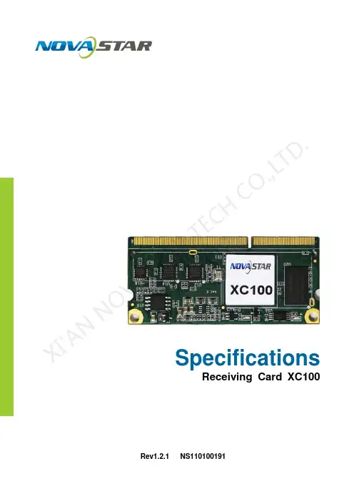
SpecificationsReceiving Card XC100Rev1.2.1NS110100191XI 'AN NOVA S T AR T E C H CO .,LT D.OverviewXC100 is super-small full function high-end mini receiving card rolled out lately by NovaStar. Compared with traditional receiving card, XC100 is more flexible in usage and DDR3 SODIMM port adopted renders it to adapt to various electrical structures easily; as a result, one module card is suitable for all applications, greatly reducing the types of module cards to be purchased.XC100 single card can load pixel of 256*256, supporting such utility functions as intelligent module management, LED display human-computer interaction and built-in voltage temperature detection. Specific circuit and program design of XC100 can effectively reduce electromagnetic radiation of the system, helping users to make their products pass EMC certification easily.Such a powerful XC100 is bound to usher in a new age of receiving card! Features 1) Single card supports pixel points of 256*256.2) Single card supports parallel output of 24-module RGB signal, extending to parallel data of 48-module RGB at maximum.3) Any scanning types within 1-1/32 scan and 595 serial decoding scanning aresupported.4) All mainstream LED driving chip like regular chip and PWM chip are supported. 5) High gray scale and high refresh rate is supported. 6) Pixel-by-pixel calibration of brightness degree is supported.7) Perfect special shape support; Random alignment, random test pixel, special-shapedmodule, special-shaped cabinet and special-shaped LED display make load more easily.8) Seamless switching of various hot backups including loop backup, dual card backup,dual power supply backup, etc. are supported.9) Human-computer interaction of cabinet and LED display is supported. 10) One-way voltage and temperature detection is available.11) Intelligent module is supported, with the functions of storing and managing calibrationcoefficient, module information and moudle parameters, as well as row line detection and LED pixel-by-pixel error detection without the need of monitoring card. 12) Special EMC design effectively reduces electromagnetic radiation.XI 'A N N O VA S T A R T E C H C O .,LT D.AppearanceNotes1: Positioning hole is connected to GND.DimensionsUnit: mmXI 'AN NOVA S T AR T E C H CO .,LT D.Output Interface DefinitionIntelligentmodule portX I'A NN OV AS TA RT EC HC O.,L TD.Gigabit network portX I N OV AS TA RT EC HC O.,L TD.X IX ISpecifications X I T E C。
产品规格书
接收卡MRV470
本文中的照片仅供参考,请以购买的实物为准
Rev1.1.3
NS110000258
西
安
诺瓦
电
子科技有
限公司
概述
MRV470是接收卡MRV270的EMC 版本,有效降低整个系统的电磁辐射。
功能特性
1) 单卡输出RGB 数据24组; 2) 单卡带载像素为256×226;
3) 支持灯板Flash 管理功能,可用来存储校正系数和灯板信息; 4) 支持配置文件回读; 5) 支持温度监控;
6) 支持网线通讯状态检测; 7) 支持供电电压检测;
8) 支持逐点亮色度校正; 9) 支持逐点亮色度校正;
10) 支持接收卡预存画面设置; 11) 符合欧盟RoHs 标准;
12) 符合欧盟CE-EMC Class B 标准。
西
安
诺瓦
电
子科
技
有
限公
司
接口定义
控制系统支持24组RGB并行数据模式,接口定义如下:
公司
尺寸
板卡厚度不大于2mm ,总厚度(板卡厚度+正反面器件厚度)不大于18mm 。
单位:mm
外观说明
提示:本文中的照片仅供参考,请以购买的实物为准。
西安
诺
瓦电
子
科
技
有
限公
司
J4(灯板Flash管理接口)定义:
J9定义(灯座):
技术参数
技有
附录
串行译码电路:
电子科技
有限
公司
西安
诺瓦。
接收卡规格书产品版本:V1.0.0文档编号:NS120000328接收卡TR100规格书www.novastar-l 更新记录V1.0.0i接收卡TR100规格书www.novastar-l ed.c n目录1概述 (1)2产品特性 (2)2.1提升显示效果 (2)2.2提升可维护性 (2)2.3提升硬件可靠性 (3)2.4提升软件可靠性 (3)3接口定义 (4)3.1 32组并行数据接口 (4)3.2扩展功能参考设计 (7)4外观 (8)5尺寸 (9)6产品规格 (10)接收卡TR100规格书www.novastar-l ed.c n1概述TR100是诺瓦科技推出的新一代接收卡,单卡带载384×384像素。
TR100支持1.0/2.3(S AA)同轴接口,使系统的连接和数据传输更加可靠。
支持SerDes技术,具有低延迟特性。
同时,T R100支持18B it+灰度输出,有效处理LED显示屏因亮度降低带来的灰度损失问题,使图像更细腻。
接收卡TR100规格书规格书备注2.RGB 数据组必须成组使用。
备注3.运行指示灯为低电平有效。
备注4.OE_RED、OE_GREEN、OE_BLUE 为显示使能引脚。
OE_RGB 不分开控制时,使用OE_RED。
当使用PWM 芯片时,为GCLK 信号。
备注5.RFU1~18 是预留扩展功能接口,详细信息请参见“3.2 扩展功能参考设计”。
规格书www.novastar-l ed.c n4外观本文中的产品照片仅供参考,实际出厂产品安装散热片,请以实际购买到的产品为准。
TR100使用的高密度接插件的母座(R eceptacle)型号如表4-1所示。
公座(P LUG)型号可以根据实际需求选择。
4-1规格书www.novastar-l ed.c n5尺寸(单位:m m)。

CVT4K-SFiber ConverterSpecificationsProduct Version: V 1.0. 1Document Number: NS1 10100 433Copyright © 2018 Xi'an NovaStar Tech Co., Ltd. All Rights Reserved.No part of this document may be copied, reproduced, extracted or transmitted in any form or by any means without the prior written consent of Xi'an NovaStar Tech Co., Ltd.Trademarkis a trademark of Xi'an NovaStar Tech Co., Ltd.StatementYou are welcome to use the product of Xi'an NovaStar Tech Co., Ltd. (hereinafter referred to as NovaStar). This document is intended to help you understand and use the product. For accuracy and reliability, NovaStar may make improvements and/or changes to this document at any time and without notice. Any problem in use or any good suggestion, please contact us through ways provided in the document. We will do our utmost to solve the problems and adopt the suggestions after evaluation as soon as possible.XI'ANNOVASTARTECHCO.,LTD.Change HistoryChange HistoryTECHNOVASTARXI'ANContentsContentsChange History ................................................................................................................................ ii Contents . (iii)1 Safety (1)1.1 Storage and Transport Safety ...................................................................................................................... 1 Installation and Use Safety .......................................................................................................................... 1 1.22 Overview ......................................................................................................................................... 2 3 Features . (3)4 A ppearance (4)5 Dimensions .................................................................................................................................... 6 6 Specifications ................................................................................................................................. 7 FCC Caution .. (87)XI'ANNOVASTARTECHCO.,LTD.XI'ANNOVASTARTECHCO.,LTD.1 Safety1 SafetyThis chapter illustrates safety of the CVT4K-S fiber converter to ensure the product'sstorage, transport, installation and use safety. Safety instructions are applicable to allpersonnel who contact or use the product. First of all, pay attention to following points.● Read through the instructions. ● Retain all instructions. ●Comply with all instructions.1.1 Storage and Transport Safety●Pay attention to dust and water prevention. ● Avoid long-term direct sunlight.● Do not place the product at a position near fire and heat. ● Do not place the product in an area containing explosive materials. ● Do not place the product in a strong electromagnetic environment. ●Place the product at a stable position to prevent damage or personal injury caused by dropping.●Save the packing box and materials which will come in handy if you ever have to store and ship the product. For maximum protection during storage and shipping, repack the product as it was originally packed at the factory. 1.2 Installation and Use Safety● Only trained professionals may install the product.● Plugging and unplugging operations are prohibited when the power is on. ●Ensure safe grounding of the product.●Always wear a wrist band and insulating gloves.●Do not place the product in an area having frequent or strong shake.●Perform dust removing regularly.●Contact NovaStar for maintenance at any time, rather than have the productdisassembled and maintained by non-professionals without authorization.●Replace faulty parts only with the spare parts supplied by NovaStar.2 OverviewFiber Converter CVT4K-S Specifications3 Features2OverviewThe CVT4K-S is a high performance fiber converter developed by NovaStar independently. Featuring photoelectric conversion of signals, the CVT4K-S realizes signal transmission via optical fiber and twisted pair. It allows long-distance signal transmission that is stable and not be easily interfered. Being easy to use, the CVT4K-S makes it convenient to connect terminal devices as well as simpler for onsite wiring connections.XI'ANNOVASTARTECHCO.,LTD.Fiber Converter CVT4K-S Specifications4 Appearanc e3Features●Supports 16 Neutrik Ethernet inputs and outputs.● Supports 4 optical fiber inputs and outputs. Two of them are master inputsand outputs and the other two are the backups.● Features dual-power redundancy backup inside for more stability and reliability. ● Features 2 types of power connectors (3-pin power socket and PowerCON),satisfying different needs of customers.● Features various indicators on the front panel, showing device statuses clearly. ●Features USB and Ethernet control connectors, making it more flexible and much easier to connect the control computer.XI'ANNOVASTARTECHCO.,LTD.Fiber Converter CVT4K-S Specifications4AppearanceFront PanelIndicators are on the middle area of the front panel:●OPT1 / O PT3 correspond to the indicators of Ethernet ports 1 – 8. When a green indicator is always on, it denotes that the corresponding port connection works. When a yellow indicator is flashing, it denotes that the corresponding port is transmitting data. When a yellow indicator is always on, it denotes that thecorresponding port does not transmit data. ● PWR : Power indicator. ● STAT : Device status●OPT2 / O PT4 correspond to the indicators of Ethernet ports 9 – 16. When a green indicator is always on, it denotes that the corresponding port connection works. When a yellow indicator is flashing, it denotes that the corresponding port is transmitting data. When a yellow indicator is always on, it denotes that the corresponding port does not transmit data. ● When the small green triangle indicator is always on, it denotes that the OPT connection works.Note:OPT1 corresponds to Ethernet ports 1 – 8 and OPT2 corresponds to Ethernet ports 9 – . In addition, OPT3 is the backup of OPT1 and OPT4 is the backup of OPT2. 16XI'ANNOVASTARTECHCO.,LTD.Fiber Converter CVT4K-SSpecifications 4 Appearance Rear PanelNOVASTAR XI'ANFiber Converter CVT4K-SSpecifications 5 Dimensions5DimensionsCO.,LTD.TECHNOVASTARXI'ANUnit: mm Fiber Converter CVT4K-SSpecifications 6 SpecificationsXI'ANFiber Converter CVT4K-S Specifications7 FCC Caution7FCC CautionAny changes or modifications not expressly approved by the party responsible for compliance could void the user's authority to operate the equipment.This device complies with part 15 of the FCC Rules. Operation is subject to thefollowing two conditions: (1) This device may not cause harmful interference, and (2) this device must accept any interference received, including interference that may cause undesired operation.Note: This equipment has been tested and found to comply with the limits for a Class A digital device, pursuant to part 15 of the FCC Rules. These limits are designed to provide reasonable protection against harmful interference when the equipment isoperated in a commercial environment. This equipment generates, uses, and canradiate radio frequency energy and, if not installed and used in accordance with the instruction manual, may cause harmful interference to radio communications.Operation of this equipment in a residential area is likely to cause harmful interference in which case the user will be required to correct the interference at his own expense.XI'ANNOVASTARTECHCO.,LTD.。
Rev1.0.0 NS110100308S X100HDMI Receiving CardDeveloped by NovaStar, SX100 is a two-in-one control card combining sending and receiving capabilities, greatly simplifying the connection of LED display system and making user experience much better.A single card is capable of loading 512×384 pixels and supports one HDMI video input and one HDMI video output for cascading. SX100 allows module flash management, smart module management, built-in voltage and temperature detection, etc.X I'A NN OV AS TA RT EC HC O.,L TD.Features●The capacity of a single card is 512×384 pixels.●One HDMI 1.4 video input interface supporting up to 1080p.●One 1080p HDMI video output interface for cascading.● A single card is capable of outputting 32 groups of RGB data.●One 100M Ethernet control interface.●One USB serial control interface.●Test patterns are displayed while self-testing if there is no video input.●Supports module Flash management allowing to store calibration coefficients and moduleinformation.●Supports pixel level brightness and chroma calibration.●Supports temperature monitoring.●Supports supply voltage detection.●Supports configuration file readback.●EU RoHs compliant.●EU CE-EMC compliant.X I'A NN OV AS TA RT EC HC O.,L TD.Interface DefinitionR T E CHC O.,L TD.Note1: 5.0V is recommended as the input power VCC.Note2: RGB data group must be used in pairs.Note3: The signal of operating indicator is low active.Note4: OE_RED, OE_GREEN and OE_BLUE are display enabled pins. In case that OE_RGB are not controlled separately, OE_RED signal is applied. When PWM chip is used, GCLK signal is enabled.Note5: Interfaces for extended functions are reserved. See details in the reference designs of other extended functions.X I'A NN OV AS TA RT EC HC O.,L TD.Appearance FrontBackX I'A NN OV AS TA RT EC HC O.,L TD.ApplicationMultiple cards can be cascaded as below.Static IP address of Ethernet port: 192.168.0.40X I'A NN OV AS TA RT EC HC O.,L TD.DimensionsSX100 dimensions (mm)X I'A NN OV AS TA RT EC HC O.,L TD.Technical ParametersXI'AN NOVASTAR TECH CO., LTD.No. 68, 2nd Keji Road, High-tech Industrial Development Zone, Xi'an 710075, P .R. ChinaPhone: +86-29-68216000 Fax: +86-29-84507072www.novastar.techCopyright © 2017 Xi’an NovaStar Tech Co., Ltd. All Rights Reserved. E&OEXI 'AN NOVA S T AR T E C H CO .,L。
X200-1Receiving CardSpecificationsDocument Version: V1.2.0Document Number: NS110100469Specifications Change HistoryChange HistorySpecifications ContentsContentsChange History (i)1 Safety (1)2 Overview (2)3 Features (3)4 Hardware Structure (4)4.1 Appearance (4)4.2 Dimensions (5)4.3 Definition of Data Interface (6)5 Specifications (9)Specifications 1 Safety1 SafetyThis chapter illustrates safety of the X200-1 receiving card to ensure the product’sstorage, transport, installation and use safety. Safety instructions are applicable to allpersonnel who contact or use the product. First of all, pay attention to the followingpoints.●Read through the instructions.●Retain all instructions.●Comply with all instructions.Storage and Transport Safety●Pay attention to dust and water prevention.●Avoid long-term direct sunlight.●Do not place the product at a position near fire and heat.●Do not place the product in an area containing explosive materials.●Do not place the product in a strong electromagnetic environment.●Place the product at a stable position to prevent damage or personal injurycaused by dropping.●Save the packing box and materials which will come in handy if you ever have tostore and ship the product. For maximum protection during storage andshipping, repack the product as it was originally packed at the factory. Installation and Use Safety●Only trained professionals may install the product.●Plugging and unplugging operations are prohibited when the power is on.●Ensure safe grounding of the product.●Always wear a wrist band and insulating gloves.●Do not place the product in an area having frequent or strong shake.●Perform dust removing regularly.●Contact us for maintenance at any time, rather than have the productdisassembled and maintained by non-professionals without authorization.●Replace faulty parts only with the spare parts supplied by us.2 Overview The X200-1 is a small receiving card with multiple functions provided by Leyard III, featuring a loading capacity of 256×256 pixels.The X200-1 supports pixel level brightness and chroma calibration, which effectively removes color difference, greatly improves display consistency of LED images, and presents finer displays to users.3 Features●Outputs 32 groups of RGB parallel data.●Supports 1/32 scan.●Supports readback of configuration file.●Supports monitoring of temperature, power voltage, and Ethernet cablecommunication status.●Supports pixel level brightness and chroma calibration.●Supports high grayscale and high refresh rate.●Supports setting of images pre-stored in the receiving card.●Supports dual card backup.●Supports dual power backup.●Supports loop backup.●Supports smart module, which stores and manages calibration coefficients,module information and relevant parameters.4 Hardware Structure 4.1 AppearancePictures shown in this document are for illustration purpose only. Actual product maydiffer.4.2 DimensionsThe unit of dimension chart is “mm”. The location holes are connected to signalgrounds (GND).4.3 Definition of Data Interface 32 Groups of RGB Parallel Data ModeSpecifications 4 Hardware StructureSpecifications 5 Specifications5 Specifications。