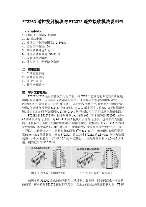
DIN 472
- 格式:pdf
- 大小:557.85 KB
- 文档页数:12

October 2011Translation by DIN-Sprachendienst.English price group 12No part of this translation may be reproduced without prior permission ofDIN Deutsches Institut für Normung e. V., Berlin. Beuth Verlag GmbH, 10772 Berlin, Germany,has the exclusive right of sale for German Standards (DIN-Normen).ICS 21.060.60!$y6q"1861978www.din.de DDIN 472Retaining rings for bores –Normal type and heavy typeEnglish translation of DIN 472:2011-10Sicherungsringe (Halteringe) für Bohrungen –Regelausführung und schwere Ausführung Englische Übersetzung von DIN 472:2011-10Anneaux d’arrêt pour alésages –Type standard et type robusteTraduction anglaise de DIN 472:2011-10©SupersedesDIN 472:2011-05www.beuth.deDocument comprises pagesIn case of doubt, the German-language original shall be considered authoritative.2301.12DIN 472:2011-102 A comma is used as the decimal marker.ContentsPageForeword (3)1 Scope (4)2 Normative references (4)3 Symbols (5)4 Dimensions and design details (6)5 Material (16)6 Finish (16)7 Testing (17)7.1 Testing the material (17)7.2 Bend and fracture test (17)7.3 Testing the deformation (17)7.3.1 Testing the conical deformation (17)7.3.2 Testing the spiral flatness (18)7.4 Testing the function (permanent set and grip test) (18)7.5 Acceptance inspection (19)8 Load bearing capacity (19)8.1 General (19)8.2 Load bearing capacity of groove F N (19)8.3 Load bearing capacity of retaining ring F R (20)9 Design of the groove (21)9.1 Groove diameter d2 (21)9.2 Groove width m (21)9.3 Design of the groove base (22)10 Assembly (23)11 Designation (23)DIN 472:2011-103ForewordThis standard has been prepared by Working Committee NA 067-00-09 AA Verbindungselemente ohne Gewinde of the Normenausschuss Mechanische Verbindungselemente (Fasteners Standards Committee). Attention is drawn to the possibility that some of the elements of this document may be the subject of patent rights. DIN shall not be held responsible for identifying any or all such patent rights.The DIN 4000-162-5 tabular layout of product properties shall apply to retaining rings covered in this standard. AmendmentsThis standard differs from DIN 472:1981-09 as follows: a) normative references have been updated;b) use of other materials subject to agreement is no longer permitted;c) the tolerances on radial run-out have been deleted from Figure 2 (formerly Figure 3); d) Figure 10 “Design of groove base” has been included in 9.3;e) in Clause 10 (formerly Clause 9), Figure 11 (formerly Figure 14) has been revised; f)examples of designation for retaining rings with corrosion protection have been included;g) the specifications for load bearing capacity and assembly have been revised; h) the standard has been editorially revised.Compared with DIN 472:2011-05 the following corrections have been made:a) in the list of amendments items c) and e) have been rendered more precise and item d) has beencorrected; b) Figures 6 and 7 have been corrected;c) in 7.4, the reference to the associated figure has been corrected;d) in 8.3, the first paragraph has been deleted (identical in content with second paragraph); e) the illustration of the shaft in Figures 9 a) to 9 d) has been brought in line with Figure 2; f)a reference to the standard covering the relevant tabular layout of product properties has been included.Previous editionsDIN 471 and DIN 472 Supplement 1: 1945-01, 1954x-03DIN 472: 1941-12, 1942-11, 1952-01, 1954x-01, 1981-09, 2011-05 DIN 472-1: 1965-03 DIN 472-2: 1965-03 DIN 995: 1970-01DIN 472:2011-1041 ScopeThis standard specifies requirements for retaining rings for bores and lays down design details for the grooves into which such rings are fitted.NOTE Retaining rings are used to hold components or assemblies (e.g. rolling bearings) in bores and are suitable for the transmission of axial forces.2 Normative referencesThe following referenced documents are indispensable for the application of this document. For dated references, only the edition cited applies. For undated references, the latest edition of the referenced document (including any amendments) applies. DIN 988, Shim rings and supporting ringsDIN 4000-162, Tabular layout of properties — Part 162: Washers and rings DIN 5256, Pliers for retaining rings for boresDIN 50938, Black oxide coatings on iron or steel — Requirements and test methodsDIN EN 10132-4, Cold-rolled narrow steel strip for heat-treatment — Technical delivery conditions — Part 4: Spring steels and other applicationsDIN EN 12476, Phosphate conversion coatings of metals — Method of specifying requirements DIN EN ISO 3269, Fasteners — Acceptance inspection DIN EN ISO 4042, Fasteners — Electroplated coatingsDIN EN ISO 6507-1, Metallic materials — Vickers hardness test — Part 1: Test methodDIN EN ISO 6508-1, Metallic materials — Rockwell hardness test — Part 1: Test method (scales A, B, C, D, E, F, G, H, K, N, T)DIN EN ISO 9227, Corrosion tests in artificial atmospheres — Salt spray tests DIN EN ISO 18265, Metallic materials — Conversion of hardness valuesDIN ISO 2859-1, Sampling procedures for inspection by attributes — Part 1: Sampling schemes indexed by acceptance quality limit (AQL) for lot-by-lot inspectionDIN 472:2011-1053 Symbolsa radial width of the lugb radial width of retaining ring opposite the aperturec distance between measuring plates for testing spiral flatnessd 1 bore diameter d 2 groove diameterd 3 external diameter of retaining ring in the unstressed stated 4 minimum centre line diameter of bore during assembly, calculated as: d 4 = d 1 – 2,1 ad 5 diameter of the assembly holes E modulus of elasticityF force acting on the retaining ring when testing conical deformationF N load bearing capacity of groove at a yield point of the grooved material of 200 MPa (see 8.2) F R load bearing capacity of retaining ring with sharp-edged abutment of a machine component (see 8.3) F Rg load bearing capacity of retaining ring for abutment with edge distance g (see 8.3) g edge distance of the machine component abutting the retaining ring h distance between the plates when testing conical deformation m groove width n edge margin R eL yield pointr curvature in the groove base or test jaws s thickness of retaining ringtgroove depth with nominal sizes of d 1 and d 2DIN 472:2011-1064 Dimensions and design detailsThe designs shown in Figure 1 are for illustrative purposes only; however, the dimensions of retaining rings and grooves shall be as specified in Tables 1 and 2. The tolerances specified relate to retaining rings in their uncoated condition.UnstressedShape of ring at manufacturer’s discretiona)b)Detail Xd 1 ≤ 300 mmd 1 ≥ 170 mm at manufacturer’sdiscretiond 1 ≥ 25 mm atmanufacturer’s discretionKey 1BoreFigure 1 — Dimensions of retaining ring (notation)DIN 472:2011-10Figure 2 — Example of installationValues for peak-to-valley height for groove base and loaded edge shall be specified on a case-by-case basis. The design of the groove base shall be as specified in 9.3.7DIN 472:2011-108 Table 1 — Normal typeDIN 472:2011-10 Table 1(continued)9DIN 472:2011-1010 Table 1(continued)DIN 472:2011-10 Table 1 (continued)11DIN 472:2011-1012 Table 1 (continued)DIN 472:2011-10 Table 1 (continued)13DIN 472:2011-1014 Table 2 — Heavy typeDIN 472:2011-10 Table 2 (continued)15DIN 472:2011-10165 MaterialC67S or C75S spring steel as in DIN EN 10132-4 (at the manufacturer’s discretion). The hardness shall be as specified in Table 3.Table 3 — Hardness of retaining rings6 FinishRetaining rings shall be free from burr.Retaining rings are normally supplied provided with corrosion protection in accordance with Table 4 (at the manufacturer's discretion). No special details concerning this condition on delivery need be stated in the designation of a retaining ring.Table 4 — Anti-corrosion treatment of retaining ringsIf a particular anti-corrosion treatment is required, either of the type specified in Table 4 or of a different type, the designation of the retaining ring shall be supplemented accordingly.In the case of retaining rings provided with a coating other than those specified in Table 4, the upper limit of the ring thickness s may be exceeded by the thickness of the coating required. This shall be taken into account when dimensioning the groove.NOTE 1 When applying surface coatings to retaining rings in bulk quantities, it is not possible to maintain closely toleranced coating thicknesses.NOTE 2 DIN EN ISO 4042 shall be observed regarding the risk of hydrogen-induced delayed brittle fracture in the case of retaining rings with electroplated coating. NOTE 3An example of designation is given in Clause 11.DIN 472:2011-10177 Testing7.1 Testing the materialVickers hardness test in accordance with DIN EN ISO 6507-1 Rockwell hardness test in accordance with DIN EN ISO 6508-1 In cases of doubt, the Vickers hardness test is decisive.7.2 Bend and fracture testTesting the retaining ring for ductility shall be carried out in accordance with Figure 3.Figure 3 — Bend testOne half of the retaining ring is clamped between two jaws, one of which has a radius equal to the thickness of the ring (r = s ), see Figure 3. The ring is then bent through 30° by repeated light hammer blows or using a lever, following which there shall be no fractures or cracks in the ring.7.3 Testing the deformation7.3.1 Testing the conical deformationThe retaining ring is placed between two parallel plates and loaded as shown in Figure 4. The distance h – s measured under force Fshall not exceed the maximum value given in Table 5.Key FForceFigure 4 — Testing the conical deformationDIN 472:2011-1018Table 5 — Conical deformation7.3.2 Testing the spiral flatnessThe retaining ring shall fall through two parallel, perpendicular plates with a clearance c (see Figure 5) as given in Table 6.Table 6 — Spiral flatnessFigure 5 — Testing the spiral flatness7.4 Testing the function (permanent set and grip test)The retaining ring shall be passed three times through a taper with a diameter of 0,99 × d 1 as shown in Figure 11, which may cause permanent deformation. The ring shall then fit in a bore with a diameter d 2 equal to the maximum groove diameter, where it shall be held under its own weight.DIN 472:2011-10197.5 Acceptance inspectionFor acceptance inspection, the principles of testing and acceptance specified in DIN EN ISO 3269 shall apply. See Table 7 for characteristics and Table 8 for the acceptance quality level.Table 7 — CharacteristicsTable 8 — Acceptable quality level AQLIf other sampling plans are to be applied, this shall be agreed at the time of ordering. For hardness testing, DIN EN ISO 3269 shall apply.The hardness test of retaining rings shall be regarded as a destructive test.8 Load bearing capacity8.1 GeneralDimensioning of a retaining ring assembly requires separate calculations for the load bearing capacity of the groove F N and for the load bearing capacity of the retaining ring F R . In each case the resulting lower value is decisive. The load bearing capacities listed in Tables 1 and 2 (F N , F R , F Rg ) contain no safety factor against yield under static loading or against fatigue fracture under dynamic loading. There is at least twice the level of safety against fracture under static loading.8.2 Load bearing capacity of groove F NThe values of F N given in Tables 1 and 2 apply for a yield point of the material in the region of the bore groove of R eL = 200 MPa as well as for the given nominal groove depths t and edge margins n .The load bearing capacity F'N for deviating groove depths t ' and yield points R 'eL shall be calculated using Equation (1):200'''eLN N R t t F F ⋅⋅= (1)DIN 472:2011-10208.3 Load bearing capacity of retaining ring F RThe values of F R given in Tables 1 and 2 apply for an assembly over the maximum diameter 1,01 × d 1 (seeClause 10) and for a sharp-edged abutment of the machine component (see Figure 6).Key 1Retaining ringKey 1Retaining ringFigure 6 — Sharp-egded abutmentFigure 7 — Abutment with edge chamferingdistance (chamfering or rounding)The values of F Rg apply to an abutment with an edge chamfering distance g (see Figure 7). The values of F R and F Rg apply to ring materials with a modulus of elasticity of 210 000 MPa.If the existing edge chamfering distance g ' deviates from the values specified in Tables 1 and 2, then, for conversion, the load bearing capacity of the retaining ring is indirectly proportional to the edge chamfering distance:''Rg Rg g g F F ⋅= (2)NOTEIf F 'Rg with smaller values of g ' is greater than F R , then F R applies.If the existing forces cannot be accommodated because the edge chamfering distance is too great, then asharp-edged abutment is to be made by means of a supporting ring complying with DIN 988 (see Figure 8).Key 1 Retaining ring 2Supporting ringFigure 8 — Sharp-edged abutment at the retaining ring using a supporting ringDIN 472:2011-10219 Design of the groove9.1 Groove diameter d 2The groove diameters d 2 specified in Tables 1 and 2 are selected so that the retaining rings are seated in the groove with prestress.NOTE Greater groove diameters are possible if prestress can be dispensed with. The upper limit is: d 2max = d 3min .9.2 Groove width mAs a rule, tolerance zone H13 applies for the groove widths specified in Tables 1 and 2. With unilateral force transmission, the grooves can be widened and/or chamfered towards the relieving side. The groove width has no influence on the load bearing capacity of the retaining ring joint. Companies can therefore specify their own groove shapes and widths.If the retaining ring is to alternately transmit the forces onto the groove walls in both directions, the groove width m shall as far as possible be matched to the ring thickness s , e.g. by also reducing the tolerance. SeeFigures 9a) to 9d) for groove shapes.a)b)c)d) Figure 9 — Groove shapesDIN 472:2011-10229.3 Design of the groove baseThe rectangular groove is the standard form (see Figure 9a)). The radius r on the loaded side shall not exceed 0,1 × s . Other suitable groove shapes are shown in Figures 9b) to 9d). In the case of a sharp-edged rectangular groove, the notch sensitivity of the material used produces a corresponding notch effect factor.Details of the groove base design are shown in Figure 10.Key1 Point for measuring perpendicularity 2Possible contours a Tolerance zone Figure 10 — Design of groove baseDIN 472:2011-1023 10 AssemblyRetaining rings shall be assembled by means of pliers conforming to DIN 5256 or using tapers.During assembly care shall be taken to ensure that the ring is contracted only to the extent necessary for insertion into the bore, i.e. to a diameter not smaller than 0,99 × d 1. If necessary, pliers equipped with limiting screws (set screw) shall be used. The most reliable protection against overexpansion is assembly using a taper (see Figure 11). Where an additional sleeve is to be provided, e.g. to install rings with a larger edge margin n or to protect the bore surface during assembly, it is recommended that the manufacturer beconsulted.a)b) c)Key1 Pressure pin2 Retaining ring3 Taper4 Groove5 HousingFigure 11 — Taper assembly 11 DesignationEXAMPLE 1 Designation of a retaining ring for a bore diameter (nominal size) d 1 = 40 mm and with a thicknesss = 1,75 mm: Retaining ring DIN 472 — 40 × 1,75EXAMPLE 2 If, by way of departure from Table 4 rings with a specific corrosion protection are required, this shall be indicated in the designation by adding the relevant symbol. For electroplated coatings, the symbols specified in DIN EN ISO 4042 shall apply, e.g.:Retaining ring DIN 472 — 40 × 1,75 — A3KEXAMPLE 3 For phosphate coatings according to Table 4, serial number 1 shall apply:Retaining rings DIN 472 — 40 × 1,75 — 1。
一、覆銅板的分類對于覆銅板類型﹐常按不同的規則﹐有不同的分類。
1﹑按覆銅板的機械剛性划分按覆銅板的機械剛性﹐可分為剛性覆銅板和撓性覆銅板。
通常撓性覆銅板大量使用的是在聚酰亞胺或聚酯薄膜上覆以銅箔。
其成品很柔軟﹐具有優異的耐折性﹐近年﹐帶載式半導體封裝器件的發展﹐為配合所需的有機樹脂帶狀封裝基體的需要﹐還出現了環氧玻纖基薄型覆銅箔帶的產品。
2﹑按不同絕緣材料﹑結構划分按不同絕緣材料﹑結構﹐可分為有機樹脂類覆銅板﹑金屬基(芯)覆銅板﹑陶瓷基覆銅板。
3﹑按覆銅板的厚度划分按覆銅板的厚度﹐可分為常規板和薄型板。
一般將厚度(不含銅箔厚度)小于0.8mm 的覆銅板﹐稱為薄板(IPC 標准為0.5mm)﹐環氧玻纖布基的0.8mm 以下薄型板可適于沖孔加工﹐0.8mm 及其以下的玻纖布覆銅板可作為多層印制電路板制作用的內芯板。
4﹑按增強材料划分覆銅板使用某種增強材料﹐就將該覆銅板稱為某材料基板。
常用的不同增強材料的剛性有機樹脂覆銅板有三大類﹕玻纖布基覆銅板﹑紙基覆銅板﹑復合基覆銅板。
另外﹐特殊增強材料構成的覆銅板還有﹕芳香聚酰胺纖維無紡布基覆銅板﹑合成纖維布基覆銅板等。
所謂復合基覆銅板﹐主要是指絕緣層表面層和芯部采用了兩種增強材料組成的覆銅板﹐在復合基覆銅板中﹐最常見的是CEM-1 和CEM-3 兩大類型覆銅板。
5﹑按照阻燃等級划分按照UL 標准(UL94﹑UL746E)阻燃等級划分有非阻燃型和阻燃型覆銅板。
一般將按UL 標准檢測達到阻燃HB 級的覆銅板﹐稱為非阻燃類板(俗稱HB 板)﹐將達到阻燃V0 級的覆銅板﹐稱為阻燃類板(俗稱V0 板)﹐這種板“HB”板﹑“V0”板之稱﹐在我國對紙基板分類稱謂﹐十分流行。
二、各類覆銅板的性能特點各類基板材料都有著各自的特性。
下面﹐對它們作此方面的橫向對比。
(一) 酚醛紙基板酚醛紙基板﹐是以酚醛樹脂為粘合劑﹐以木漿纖維紙為增強材料的絕緣層壓材料。
酚醛紙基覆銅板﹐一般可進行沖孔加工﹑具有成本低﹑價格便宜﹐相對密度小的優點。