DXF文件格式详解(全)
- 格式:pdf
- 大小:2.82 MB
- 文档页数:43
部分基本描述Header 本部分包含有关图形的常规信息。
就像您⼿机中的“设置”功能⼀样,该功能包含与图形关联的不同变量及其关联的值。
例如,“标题”部分将定义DXF ⽂件使⽤的AutoCAD 版本($ ACADVER 变量)或⽤于测量⽂件⾓度的单位($ AUNITS 变量)。
Classes CLASSES 部分保存有关应⽤程序定义的类的信息,这些类的实例出现在数据库的BLOCKS ,ENTITIES 和OBJECTS 部分中。
Tables 本部分包含⼏个不同表的定义,每个表都包含许多不同的符号条⽬。
例如,线型表(LTYPE )定义了DXF ⽂件中的破折号,点,⽂本和符号的样式以及它们的缩放⽐例。
以下是在该部分中找到的表的完整列表:应⽤程序ID (APPID )表块记录(BLOCK_RECORD )表尺⼨样式(DIMSTYPE )表图层(LAYER )表线型(LTYPE )表⽂字样式(STYLE )表格⽤户坐标系(UCS )表查看(VIEW )表视⼝配置(VPORT )表Blocks 本部分包含构成图形中每个块参考的图形对象和图形实体。
Entities本部分包含图形的实际对象数据和图形实体。
这可以包括原始数据,例如,圆实体是由其厚度,中⼼点,其半径和拉伸⽅向定义的。
Objects 在这⾥,您将找到图形的⾮图形部分。
例如,AutoCAD 词典存储在此处。
DXF ⽂件格式理解所有⽂件格式都有⼀个规范,该规范描述了⽂件中信息的编码⽅式—字节排列⽅式,计算机如何加载⽂件等等。
DXF ⽂件格式是⽮量图形⽂件格式,其详细说明了如何表⽰不同的图形元素。
DXF 是⼀个⽮量图形⽂件,它捕获CAD 图形的所有元素,例如⽂本,线条和形状。
更重要的是,DXF 是⽤于在CAD 应⽤程序之间传输数据的图形交换⽂件。
然后,每个CAD 程序都会解释这组指令,并复制您的⽮量图。
它的创建者AutoDesk 发布了这些官⽅⽂件规范⽂档,这些⽂档定义了定义DXF ⽂件的语法(或⼀组规则)。
DXF文件实际上是ASCII编码文件,可以用记事本打开。
DXF 文件本质上由代码及关联值对组成。
代码(通常称为组码)表明其后的值的类型。
使用这些组码和值对,可以将DXF 文件组织到由记录组成的区域中,这些记录由组码和数据项目组成。
在DXF 文件中,每个组码和值都各占一行。
DXF 文件由多个段组成,每段都以一个0和后跟字符串SECTION 的组码开始,其后是组码2 和表示该段名称的字符串(例如,HEADER)。
每段都由定义其元素的组码和值组成。
每段都以一个0和后跟字符串ENDSEC 的组码结束。
完整的结构如下:HEADER 段。
包含图形的基本信息。
它由AutoCAD 数据库版本号和一些系统变量组成。
每个参数都包含一个变量名称及其关联的值。
CLASSES 段。
包含应用程序定义的类的信息,这些类的实例出现在数据库的BLOCKS、ENTITIES 和OBJECTS 段中。
类定义在类的层次结构中是固定不变的。
TABLES 段。
包含以下符号表的定义:APPID(应用程序标识表)BLOCK_RECORD(块参照表)DIMSTYLE(标注样式表)LAYER(图层表)LTYPE(线型表)STYLE(文字样式表)UCS(用户坐标系表)VIEW(视图表)VPORT(视口配置表)BLOCKS 段。
包含构成图形中每个块参照的块定义和图形图元。
ENTITIES 段。
包含图形中的图形对象(图元),其中包括块参照(插入图元)。
一般屏幕上显示的图形对像如直线,圆,弧等都在ENTITIES 段OBJECTS 段。
包含图形中的非图形对象。
除图元、符号表记录以及符号表以外的所有对象都存储在此段。
OBJECTS 段中的条目样例是包含多线样式和组的词典。
THUMBNAILIMAGE 段。
包含图形的预览图像数据。
此段为可选你所问的是立体(3DSOLID),它的编码比较复杂,建议你先把平面图元的DXF格式搞明白,再研究三维图元的格式,以下是一个500*150的矩形ENTITIES 段代码:SECTION 段2 段名称ENTITIES 实体段0 图元名称LWPOL YLINE 优化多段线5 图元名柄B513301F100 子类标记AcDbEntity8 图层名100 子类标记AcDbPolyline90 顶点数470 多段线标志(按位编码);默认值为0。
本文部分内容来自网络整理,本司不为其真实性负责,如有异议或侵权请及时联系,本司将立即删除!== 本文为word格式,下载后可方便编辑和修改! ==dxf格式详细说明篇一:DXF图形文件格式解析DXF图形文件格式一、DXF文件格式分析DXF文件由标题段、表段、块段、实体段和文件结束段5部分组成,其内容如下。
☆标题段(HEADER)标题段记录AutoCAD系统的所有标题变量的当前值或当前状态。
标题变量记录了AutoCAD系统的当前工作环境,如SNAP捕捉当前状态、栅格间距式样、当前图层层名及线型、颜色等。
☆表段(TABLES)表段共包含4个表,每个表又包含可变数目的表项。
这些表在文件中出现的顺序是线型表(LTYPE)、图层表(LAYER)、字样表(STYLE)、视图表(VIEW)。
☆块段(BLOCK)块段记录了所用块的块名,当前图层层名、块的种类、块的插入基点及组成该块的所有成员。
块的种类分为图形块、带有属性的块和无名块三种。
无名块包括用HATCH命令生成的剖面线和用DIM命令所完成的尺寸标准。
☆实体段(ENTITIES)实体段记录了每个实体的名称、所在图层及其名字、线型、颜色等。
☆文件结束段(EOF OF FILE)DXF文件的结束标志。
一个DXF文件由若干个组构成,每个组占两行,第一行为组的代码,第二行为组值。
组代码相当于数据类型的代码,它由CAD图形系统所规定,而组值为具体的数值,二者结合起来表示一个数据的含义和值。
例如,代码10代表一个点的X坐标,占一行,而其第二行4.5425则是点X坐标的具体数值,二者结合表示一点,其X坐标值为4.5425。
(1)组代码和组值的类型组代码为一个非负的不超过三位的整数,而组值由组代码的类型决定。
例如:代码0~9组值类型为字符型。
代码10~59组值类型为实型。
代码60~79组值类型为整型。
代码999表示解释行。
(2)组代码的含义每个组代码均有规定的含义,有些代码含义是固定的,而有些组代码则因应用场合不同而有多个含义,应具体分析。
CAD重要的DXF详细参考资料全目录AutoCAD 2000 DXF参考修正第一章-- DXF 格式概述认识本参考对象和图元的组码组码值类型按数字次序排列的组码第二章-- HEADER 区域概述HEADER 区域组码第三章-- CLASSES 区域概述CLASS区域组码第四章-- TABLES 区域概述符号表组码符号表公用组码APPIDBLOCK_RECORD DIMSTYLELAYERLTYPESTYLEUCSVIEWVPORT第五章-- BLOCKS 区域概述BLOCKS 区域组码BLOCKENDBLK第六章-- ENTITIES 区域概述图形对象的公用组码3DFACE3DSOLIDACAD_PROXY_ENTITY ARC ARCALIGNEDTEXT ATTDEFATTRIBBODYCIRCLEDIMENSIONELLIPSEHATCHIMAGEINSERTLEADERLINELWPOLYLINEMLINEMTEXTOLEFRAMEOLE2FRAMEPOINTPOLYLINERAYREGIONRTEXTSEQENDSHAPESOLIDSPLINETEXTTOLERANCETRACEVERTEXVIEWPORTWIPEOUTXLINE第7章-- OBJECTS 区域概述OBJECT区域组码公用对象组码ACAD_PROXY_OBJECT ACDBDICTIONARYWDFLT ACDBPLACEHOLDER DICTIONARY DICTIONARYVAR DIMASSOC(AutoCAD 2002新增)GROUPIDBUFFERIMAGEDEFIMAGEDEF_REACTOR LAYER_INDEXLAYOUTMLINESTYLEOBJECT_PTR PLOTSETTINGS RASTERVARIABLES SPATIAL_INDEXSPATIAL_FILTER SORTENTSTABLE XRECORD第8章-- THUMBNAILIMAGE 区域概述THUMBNAILIMAGE 区域组码第一章-- DXF 格式 (7)概述 (7)认识本参考 (7)对象和图元的组码 (7)组码值类型 (8)按数字次序排列的图元组码 (9) 第二章-- HEADER 区域 (12) 概述 (12)HEADER 区域组码 (12)第三章-- CLASSES 区域 (21) 概述 (21)CLASS区域组码 (21)第四章-- TABLES 区域 (23)概述 (23)符号表组码 (23)符号表公用组码 (23) APPID (25)BLOCK_RECORD (25) DIMSTYLE (26)LAYER (28)LTYPE (29)STYLE (30)UCS (31)VIEW (32)VPORT (34)第五章-- BLOCKS 区域 (36) 概述 (36)BLOCKS 区域组码 (37) BLOCK (37)ENDBLK (38)第六章-- ENTITIES 区域 (39) 概述 (39)图形对象的公用组码 (39)3DFACE (40)3DSOLID (41)ACAD_PROXY_ENTITY (41) ACAD_PROXY_ENTITY (42) ACAD_PROXY_ENTITY (43) ARC (44) ARCALIGNEDTEXT (44) ATTDEF (45)ATTRIB (47)BODY (48)CIRCLE (48) DIMENSION (49)公用标注组码 (49)对齐标注组码 (51)线性标注和转角标注组码 (51) 半径标注和直径标注组码 (52)角度标注组码 (53) 坐标标注组码 (54) 标注样式替代 (55) ELLIPSE (55) HATCH (56)边界路径数据 (57) 图案数据 (60) IMAGE (60) INSERT (61) LEADER (62) LINE (63) LWPOLYLINE (64) MLINE (65) MTEXT (66) OLEFRAME (67) OLE2FRAME (68) POINT (70) POLYLINE (70)多面网格 (71) REGION (72) RTEXT (73) SEQEND (73) SHAPE (74) SOLID (74) SPLINE (75) TEXT (76) TOLERANCE (78) TRACE (78) VERTEX (79) VIEWPORT (80)WIPEOUT (83)第7章-- OBJECTS 区域 (83)概述 (84)OBJECT 区域组码 (84)对象所有关系 (85)公用对象组码 (85)ACAD_PROXY_OBJECT (86)ACDBDICTIONARYWDFLT (86)ACDBPLACEHOLDER (87)DICTIONARY (88)GROUP (90)IDBUFFER (90)IMAGEDEF (91)IMAGEDEF_REACTOR (91)LAYER_INDEX (92)LAYOUT (92)MLINESTYLE (94)OBJECT_PTR (95)PLOTSETTINGS (96)RASTERVARIABLES (98)SPATIAL_INDEX (98)SPATIAL_FILTER (99)SORTENTSTABLE (100)XRECORD (101)第8章-- THUMBNAILIMAGE 区域 (101)THUMBNAILIMAGE 区域组码 (101)第一章-- DXF 格式概述DXF 格式是特定版本AutoCAD 图形文件中所包含的全部信息的标记数据的一种表示方法。
一、DXF 格式简介DXF是D rawing e X change F ile的缩写,意思为图形交换文件。
DXF 格式是特定版本 AutoCAD 图形文件中所包含的全部信息的标记数据的一种表示方法。
标记数据的意思是指在每个数据元素前都带一个称为组码的整数。
组码的值表明了其后数据元素的类型,也指出了数据元素对于给定对象(或记录)类型的含意。
图形文件中所有用户指定的信息都能够以 DXF 文件格式表示。
1.基本的DXF约定:组码将按照在DXF 文件中出现的次序列出,而且每章将以DXF文件中的相关区域来命名。
对象和图元的组码2.在 DXF 格式中,对象的定义与图元的定义不同:图元有图形表示,而对象则没有图形表示。
例如,词典是对象而不是图元。
对象通常作为非图形对象来使用,图元则作为图形对象来使用。
3.某些定义图元的组码始终会出现,而其他的组码为可选,它们仅在其值与缺省值不同时才出现。
读取 DXF 文件的程序不应该假定说明图元的组码是按照给定次序出现的。
与说明图元的组码相连的 0 组码表示此图元已结束。
0 组码将开始新图元或表示此区域已结束。
注意:图元的组码是按照CAD绘图时绘制不同图形的顺序生成的,并没有固定的顺序。
组码值类型将与组码关联的值(组值)定义为整型、浮点数型或字符串型。
下表为组码的范围。
组码值类型组码范围组值类型0-9 字符串(已经去除了255个字符的限制。
尽管所有行被限制在2049个字节之内,但每行的字节数却没有直接限制。
)10-59 双精度三维点60-79 16 位整数值90-99 32 位整数值100 字符串(最多255 个字符,对于UNICODE 字符串则更少)102 字符串(最多255 个字符,对于UNICODE 字符串则更少)105 表示十六进制句柄值的字符串140-147 双精度标量浮点值170-175 16 位整数值280-289 8 位整数值300-309 任意文字字符串310-319 表示二进制数据组的十六进制值的字符串320-329 表示十六进制句柄值的字符串330-369 表示十六进制对象标识符的字符串370-379 8 位整数值380-389 8 位整数值390-399 表示十六进制句柄值的字符串400-409 16 位整数值410-419 字符串999 注释(字符串)1000-1009 字符串(与0-9组码范围的限制一样)1010-1059 浮点值1060-1070 16 位整数值1071 32 位整数值二、DXF 格式整体结构DXF 文件完整的结构由以下段落组成:HEADER 段:包含有关图形的基本信息。
DXF_文档详解DXF的基本惯例DXF格式是特定版本AutoCAD图形文件中所包含的全部信息的标记数据的一种表示方法。
标记数据的意思是指在每个数据元素前都带一个称为组码的整数。
组码的值表明了其后数据元素的类型,也指出了数据元素对于给定对象(或记录)类型的含意。
实际上,图形文件中所有用户指定的信息都能够以DXF文件格式表示。
在AutoLISP和ARX应用程序中使用的DXF格式与上述格式基本相同,只是在某些数据组上存在着细微的差别。
如不作特殊说明,本节中所出现的组码都可以应用于DXF文件、AutoLISP应用程序和ARX应用程序。
当组码说明对于应用程序和DXF文件有所不同时(或只适用于其中之一),在组码的说明前有如下提示符:APP只用于应用程序的说明DXF只用于DXF文件的说明如果组码说明对DXF文件和应用程序都适用,那么没有提示符;否则将显示适当的提示符。
组码范围组码将与组码关联的值(组值)定义为整型、浮点数型或字符串型。
具体说明如下表:组码范围组码范围组值类型0-9 字符串(最多255个字符,对于UNICODE字符串则更少)10-59 双精度三维点60-79 16位整数值90-99 32位整数值100 字符串(最多255个字符,对于UNICODE字符串则更少)102 字符串(最多255个字符,对于UNICODE字符串则更少)105 表示十六进制句柄值的字符串140-147 双精度标量浮点值170-175 16位整数值280-289 8位整数值300-309 任意文字字符串310-319 表示二进制数据组的十六进制值的字符串320-329 表示十六进制句柄值的字符串330-369 表示十六进制对象标识符的字符串999 注释(字符串)1000-1009 字符串(最多255个字符;对于UNICODE字符串则更少)1010-1059 浮点值1060-1070 16位整数值1071 32位整数值按数字次序排列的组码下表给出了组码(或组码范围)及其说明。
dxf生成闭合曲线【实用版】目录1.DXF 文件格式简介2.闭合曲线的概念3.生成闭合曲线的方法4.应用案例正文一、DXF 文件格式简介DXF(Drawing eXchange Format)是一种常用于计算机辅助设计(CAD)和地理信息系统(GIS)的矢量图形文件格式。
它是一种开放的、基于文本的标准,由 Autodesk 公司于 1980 年代开发。
DXF 文件包含了几何图形、属性和注释等信息,广泛应用于建筑、工程和地理空间数据等领域。
二、闭合曲线的概念闭合曲线是指在平面或空间中,由一系列线段、弧线等组成的连续路径,首尾相接形成一个闭合的图形。
在 CAD 和 GIS 软件中,闭合曲线可以用于描述复杂的几何形状,如多边形、圆形等。
三、生成闭合曲线的方法在 DXF 文件中,可以通过定义多边形或复合曲线来生成闭合曲线。
下面分别介绍这两种方法:1.定义多边形多边形是由多个线段组成的封闭图形。
在 DXF 文件中,可以通过指定多边形的顶点坐标来定义一个多边形。
例如,定义一个矩形,需要提供四个顶点坐标:(x1, y1)、(x1, y2)、(x2, y2) 和 (x2, y1)。
2.复合曲线复合曲线是由多个曲线段组成的路径。
在 DXF 文件中,可以通过定义曲线段的控制点和终点来生成复合曲线。
常用的曲线段类型有二次贝塞尔曲线、三次贝塞尔曲线等。
四、应用案例在实际应用中,闭合曲线可以用于描述各种形状的区域,如城市边界、自然保护区等。
这些区域可以用于地理分析、可视化和空间查询等操作。
例如,在 GIS 软件中,可以通过读取 DXF 文件中的闭合曲线数据,生成对应的地理信息系统图层,从而实现对地理空间的分析和应用。
总之,DXF 格式是一种重要的矢量图形文件格式,可以方便地描述闭合曲线等复杂图形。
AUTOCAD-DXF文档详解DXF的基本惯例DXF格式是特定版本AutoCAD图形文件中所包含的全部信息的标记数据的一种表示方法。
标记数据的意思是指在每个数据元素前都带一个称为组码的整数。
组码的值表明了其后数据元素的类型,也指出了数据元素对于给定对象(或记录)类型的含意。
实际上,图形文件中所有用户指定的信息都能够以DXF文件格式表示。
在AutoLISP和ARX应用程序中使用的DXF格式与上述格式基本相同,只是在某些数据组上存在着细微的差别。
如不作特殊说明,本节中所出现的组码都可以应用于DXF文件、AutoLISP应用程序和ARX应用程序。
当组码说明对于应用程序和DXF文件有所不同时(或只适用于其中之一),在组码的说明前有如下提示符:APP只用于应用程序的说明DXF只用于DXF文件的说明如果组码说明对DXF文件和应用程序都适用,那么没有提示符;否则将显示适当的提示符。
组码范围组码将与组码关联的值(组值)定义为整型、浮点数型或字符串型。
具体说明如下表:组码范围组码范围组值类型0-9 字符串(最多255个字符,对于UNICODE字符串则更少)10-59 双精度三维点60-79 16位整数值90-99 32位整数值100 字符串(最多255个字符,对于UNICODE字符串则更少)102 字符串(最多255个字符,对于UNICODE字符串则更少)105 表示十六进制句柄值的字符串140-147 双精度标量浮点值170-175 16位整数值280-289 8位整数值300-309 任意文字字符串310-319 表示二进制数据组的十六进制值的字符串320-329 表示十六进制句柄值的字符串330-369 表示十六进制对象标识符的字符串999 注释(字符串)1000-1009 字符串(最多255个字符;对于UNICODE字符串则更少)1010-1059 浮点值1060-1070 16位整数值1071 32位整数值按数字次序排列的组码下表给出了组码(或组码范围)及其说明。

DXF, Revision 12Compiled by Paul BourkeMarch 1988AutoCAD can be used by itself as a complete drawing editor. In some applications, however, other programs must examine drawings created by AutoCAD or generate drawings to be viewed, modified, or plotted with AutoCAD.For example, if you've made an architectural drawing with AutoCAD, using inserted parts to represent windows, doors, and so on, you can process the drawing file and produce a bill of materials of allitems used in the drawing, or even make energy-use calculations based on the area and the number and type of windows used. Another possible application is to use AutoCAD to describe structures and then send the descriptions to a more powerful computer for finite- element structural analysis. You can compute stresses and displacements and send back information to display the deformed structure as an AutoCAD drawing.Since the AutoCAD drawing database (.dwg file) is written in a compact format that changes significantly as new features are added to AutoCAD, we do not document its format and do not recommend that you attempt to write programs to read it directly. To assist in interchanging drawings between AutoCAD and other programs, a Drawing Interchange file format (DXF) has been defined. All implementations of AutoCAD accept this format and are able to convert it to and from their internal drawing file representation.AutoCAD also supports the Initial Graphics Exchange Specification (IGES) file format. The information comprising an AutoCAD drawing can be written out in IGES format, and IGES files can be read and converted to the AutoCAD internal format.ASCII Drawing Interchange (DXF) FilesThis section describes the AutoCAD DXF (drawing interchange file) format and the commands provided to read and write these files. DXF files are standard ASCII text files. They can easily be translatedto the formats of other CAD systems or submitted to other programs for specialized analysis. AutoCAD can also produce or read a binary form of the full DXF file. This feature is described in detail later in this chapter.DXFOUT Command - Writing a DXF FileYou can generate a drawing interchange file from an existing drawing by means of the DXFOUT command:Command: dxfoutWhen AutoCAD prompts you, respond with a filename or press 5 to accept the default.The default name for the output file is the same as that of the current drawing, but with a file type of .dxf. If you specify an explicit filename, you do not need to include a file type; .dxf is assumed. If a file with the same name already exists, the existing file is deleted. If you specify the file using a file dialogue box, and a file with the same name already exists, AutoCAD tells you; allowing you to OK or cancel the deletion. Next, DXFOUT asks what precision you want for floating-point numbers and permits output of a partial DXF file containing only selected objects.Enter decimal places of accuracy (0 to 16)/Entities/Binary <6>: The Binary option is described later in this chapter.If you respond with "entities" (or just "e"), DXFOUT asks you to select the objects you want written to the DXF file. Only theobjects you select are included in the output file - symbol tables (including Block Definitions) will not be included. Once you've selected the desired objects, AutoCAD again prompts you for the numeric precision:Enter decimal places of accuracy (0 to 16)/Binary <6>:DXFIN Command - Loading a DXF FileA drawing interchange file can be converted into an AutoCAD drawing by means of the DXFIN command:Command: dxfinWhen AutoCAD prompts you, respond with the name of the drawing interchange file to be loaded.Full DXFINTo load a complete DXF file, you must use DXFIN in an empty drawing, before any entities have been drawn and before any additional Block definitions, layers, linetypes, text styles, dimension styles, named views, named coordinate systems, or named viewport configurations have been created.NOTE: If the drawing you are using as a prototype is not empty, you might find it helpful to open a new drawing using the No Prototype... button of the Create New Drawing dialogue box, as described in chapter 4 of the "AutoCAD Reference Manual." You should also be aware that some third-party applications include an acad.lsp or .mnl file that modifies your drawing upon startup.If any errors are detected during the input, the new drawing is discarded. Otherwise, an automatic ZOOM All is performed to set the drawing extents.Partial DXFINIf the current drawing is not empty, DXFIN loads only the ENTITIES section of the DXF file, adding the entities found there to the current drawing. In this case, DXFIN displays the message:Not a new drawing -- only ENTITIES section will be input.If errors are detected during such partial DXF input, the drawing is returned to the state it was in before the DXFIN command. Otherwise, the newly added entities are drawn.Auditing DXF FilesTo ensure that corrupt data is not imported into your drawing, you can instruct AutoCAD to perform an audit after importing DXF files into your drawing with DXFIN. When you use DXFIN, the default action is to perform no automatic auditing. To activate automatic auditing, use the CONFIG command:Command: configYour current AutoCAD configuration appears. Press 5 to continue. From the Configuration menu select this option:7. Configure operating parametersFrom the Operating parameter menu select this option:9. Automatic Audit after IGESIN, DXFIN, or DXBINAnswer Y to this question:Do you want an automatic audit after IGESIN, DXFIN, or DXBIN?<N>: yReturn to the graphics screen by pressing 5 three times.NOTE: This kind of audit only displays the errors AutoCAD finds; itdoes not correct them. To correct problems, use the AUDIT command on the drawing while you are in AutoCAD, or manually edit the DXF file. DXF File FormatThis section describes the format of a DXF file in detail. It contains technical information that you need only if you write your own programs to process DXF files or work with entity information obtained by certain AutoLISP and ADS functions.It would probably be helpful to produce a DXF file from a small drawing, print it out, and refer to it occasionally while readingthe information presented next.General File StructureA Drawing Interchange File is simply an ASCII text file with a file type of .dxf and specially formatted text. The overall organization of a DXF file is as follows:1. HEADER section - General information about the drawing is foundin this section of the DXF file. Each parameter has a variablename and an associated value (see table 11-3 for a list of theheader variables).2. TABLES section - This section contains definitions of nameditems.o Linetype table (LTYPE)o Layer table (LAYER)o Text Style table (STYLE)o View table (VIEW)o User Coordinate System table (UCS)o Viewport configuration table (VPORT)o Dimension Style table (DIMSTYLE)o Application Identification table (APPID)3. BLOCKS section - This section contains Block Definition entities describing the entities that make up each Block in the drawing.4. ENTITIES section - This section contains the drawing entities,including any Block References.5. END OF FILEIf you use DXFOUT's Entities option, the resulting DXF file contains only the ENTITIES section and the END OF FILE marker, and the ENTITIES section reflects only the objects you select for output. NOTE: If you select an INSERT entity, the corresponding Blockdefinition is not included in the output file.A DXF file is composed of many groups, each of which occupies two lines in the DXF file. The first line of a group is a group code, which is a positive nonzero integer output in FORTRAN I3 - that is, right-justified and blank filled in a three-character field (the exception to this is the four-digit extended entity data group codes, which are output in FORTRAN I4). The second line of the group is the group value, in a format that depends on the type of group specified by the group code. Although DXFOUT output has a fixed format, the DXFIN format is free.The specific assignment of group codes depends on the item being described in the file. However, the type of the value this group supplies is derived from the group code in the following way:Table 11-1. Group code ranges+================================+| Group code | Following value || range | ||-------------|------------------|| 0 - 9 | String ||-------------|------------------|| 10 - 59 | Floating-point ||-------------|------------------|| 60 - 79 | Integer ||-------------|------------------|| 140 - 147 | Floating-point ||-------------|------------------|| 170 - 175 | Integer ||-------------|------------------|| 210 - 239 | Floating-point ||-------------|------------------|| 999 | Comment (string) ||-------------|------------------|| 1010 - 1059 | Floating-point ||-------------|------------------|| 1060 - 1079 | Integer ||-------------|------------------|| 1000 - 1009 | String |+--------------------------------+Thus a program can easily read the value following a group code without knowing the particular use of this group in an item in the file. The appearance of values in the DXF file is not affected bythe setting of the UNITS command: coordinates are always represented as decimal (or possibly scientific notation if very large) numbers, and angles are always represented in decimal degrees with zero degrees to the east of origin.Variables, table entries, and entities are described by a group that introduces the item, giving its type and/or name, followed bymultiple groups that supply the values associated with the item. In addition, special groups are used for file separators such asmarkers for the beginning and end of sections, tables, and the file itself.Entities, table entries, and file separators are always introduced with a 0 group code that is followed by a name describing the item. NOTE: The maximum DXF file string length is 256 characters. If your AutoCAD drawing contains strings that exceed this number, those strings are truncated during DXFOUT. If your DXF file containsstrings that exceed this number, DXFIN will fail.Group CodesGroup codes are used both to indicate the type of the value of the group, as explained earlier, and to indicate the general use of the group. The specific function of the group code depends on the actual variable, table item, or entity description. This section indicates the general use of groups, noting as "(fixed)" any that always have the same function.Table 11-2. AutoCAD entity group codes (by number)+===============================================================+| Group code | Value type ||------------|--------------------------------------------------|| 0 | Identifies the start of an entity, table entry, || | or file separator. The type of entity is given || | by the text value that follows this group ||------------|--------------------------------------------------|| 1 | The primary text value for an entity ||------------|--------------------------------------------------|| 2 | A name: Attribute tag, Block name, and so on. || | Also used to identify a DXF section or table name||------------|--------------------------------------------------|| 3-4 | Other textual or name values ||------------|--------------------------------------------------|| 5 | Entity handle expressed as a hexadecimal string || | (fixed) ||------------|--------------------------------------------------|| 6 | Line type name (fixed) ||------------|--------------------------------------------------|| 7 | Text style name (fixed) ||------------|--------------------------------------------------|| 8 | Layer name (fixed) ||------------|--------------------------------------------------|| 9 | Variable name identifier (used only in HEADER || | section of the DXF file) ||------------|--------------------------------------------------|| 10 | Primary X coordinate (start point of a Line or || | Text entity, center of a Circle, etc.) ||------------|--------------------------------------------------| | 11-18 | Other X coordinates | |------------|--------------------------------------------------| | 20 | Primary Y coordinate. 2n values always | | | correspond to 1n values and immediately follow | | | them in the file | |------------|--------------------------------------------------| | 21-28 | Other Y coordinates | |------------|--------------------------------------------------| | 30 | Primary Z coordinate. 3n values always | | | correspond to 1n and 2n values and immediately | | | follow them in the file | |------------|--------------------------------------------------| | 31-37 | Other Z coordinates | |------------|--------------------------------------------------| | 38 | This entity's elevation if nonzero (fixed). | | | Exists only in output from versions prior to R11 | |------------|--------------------------------------------------| | 39 | This entity's thickness if nonzero (fixed) | |------------|--------------------------------------------------| | 40-48 | Floating-point values (text height, scale | | | factors, etc.) | |------------|--------------------------------------------------| | 49 | Repeated value - multiple 49 groups may appear | | | in one entity for variable length tables (such | | | as the dash lengths in the LTYPE table). A 7x | | | group always appears before the first 49 group | | | to specify the table length | |------------|--------------------------------------------------| | 50-58 | Angles | |------------|--------------------------------------------------| | 62 | Color number (fixed) | |------------|--------------------------------------------------| | 66 | "Entities follow" flag (fixed) | |------------|--------------------------------------------------| | 67 | Identifies whether entity is in model space or | | | paper space | |------------|--------------------------------------------------| | 68 | Identifies whether viewport is on but fully off | | | screen, is not active, or is off | |------------|--------------------------------------------------| | 69 | Viewport identification number | |------------|--------------------------------------------------| | 70-78 | Integer values such as repeat counts, flag | | | bits, or modes | |------------|--------------------------------------------------| | 210, | X, Y, and Z components of extrusion direction | | 220, | (fixed) | | 230 | | |------------|--------------------------------------------------| | 999 | Comments | |------------|--------------------------------------------------|| 1000 | An ASCII string (up to 255 bytes long) in || | extended entity data ||------------|--------------------------------------------------|| 1001 | Registered application name (ASCII string up to || | 31 bytes long) for XDATA (fixed) ||------------|--------------------------------------------------|| 1002 | Extended entity data control string ("{" or "}") || | (fixed) ||------------|--------------------------------------------------|| 1003 | Extended entity data Layer name ||------------|--------------------------------------------------|| 1004 | Chunk of bytes (up to 127 bytes long) in || | extended entity data ||------------|--------------------------------------------------|| 1005 | Extended entity data database handle ||------------|--------------------------------------------------|| 1010, | Extended entity data X, Y, and Z coordinates || 1020, | || 1030 | ||------------|--------------------------------------------------|| 1011, | Extended entity data X, Y, and Z coordinates of || 1021, | 3D world space position || 1031 | ||------------|--------------------------------------------------|| 1012, | Extended entity data X, Y, and Z components of || 1022, | 3D world space displacement || 1032 | ||------------|--------------------------------------------------|| 1013, | Extended entity data X, Y, and Z components of || 1023, | 3D world space direction || 1033 | ||------------|--------------------------------------------------|| 1040 | Extended entity data Floating-point value ||------------|--------------------------------------------------|| 1041 | Extended entity data distance value ||------------|--------------------------------------------------|| 1042 | Extended entity data scale factor ||------------|--------------------------------------------------|| 1070 | Extended entity data 16-bit signed integer ||------------|--------------------------------------------------|| 1071 | Extended entity data 32-bit signed long |+---------------------------------------------------------------+ CommentsThe 999 group code indicates that the following line is a comment string. DXFOUT does not currently include such groups in a DXF output file, but DXFIN honors them and ignores the comments. Thus, you can use the 999 group to include comments in a DXF file you've edited. For example:999This is a comment.999This is another comment.File SectionsThe DXF file is subdivided into four editable sections, plus the END OF FILE marker. File separator groups are used to delimit these file sections. The following is an example of a void DXF file with only the section markers and table headers present:0 (Begin HEADER section)SECTION2HEADERHeader variable items go hereENDSEC (End HEADER section)0 (Begin TABLES section)SECTION2TABLESTABLE2VPORT70(viewport table maximum item count)viewport table items go hereENDTABTABLE2APPID, DIMSTYLE, LTYPE, LAYER, STYLE, UCS, VIEW, or VPORT70(Table maximum item count)Table items go hereENDTABENDSEC (End TABLES section)0 (Begin BLOCKS section)SECTION2BLOCKSBlock definition entities go hereENDSEC (End BLOCKS section)0 (Begin ENTITIES section)SECTION2ENTITIESDrawing entities go hereENDSEC (End ENTITIES section)EOF (End of file)HEADER SectionThe HEADER section of the DXF file contains settings of variables associated with the drawing. These variables are set with various commands and are the type of information displayed by the STATUS command. Each variable is specified in the header section by a 9 group giving the variable's name, followed by groups that supply the variable's value. The following list shows the header variables and their meanings.Although this list is very similar to the list of system variablesin Appendix A of this manual, the two lists are not identical. Be sure you're referring to the proper list.NOTE: $AXISMODE and $AXISUNIT are no longer functional in Release 12.Table 11-3. DXF system variables+===============================================================+| Variable | Type | Description ||----------------|--------|-------------------------------------|| $ACADVER | 1 | The AutoCAD drawing database || | | version number; AC1006 = R10, || | | AC1009 = R11 and R12 ||----------------|--------|-------------------------------------|| $ANGBASE | 50 | Angle 0 direction ||----------------|--------|-------------------------------------|| $ANGDIR | 70 | 1 = clockwise angles, 0 = || | | counterclockwise ||----------------|--------|-------------------------------------|| $ATTDIA | 70 | Attribute entry dialogs, 1 = on, || | | 0 = off ||----------------|--------|-------------------------------------|| $ATTMODE | 70 | Attribute visibility: 0 = none, || | | 1 = normal, 2 = all ||----------------|--------|-------------------------------------|| $ATTREQ | 70 | Attribute prompting during INSERT, || | | 1 = on, 0 = off ||----------------|--------|-------------------------------------|| $AUNITS | 70 | Units format for angles ||----------------|--------|-------------------------------------|| $AUPREC | 70 | Units precision for angles | |----------------|--------|-------------------------------------| | $AXISMODE | 70 | Axis on if nonzero (not functional | | | | in Release 12) | |----------------|--------|-------------------------------------| | $AXISUNIT | 10, 20 | Axis X and Y tick spacing | | | | (not functional in Release 12) | |----------------|--------|-------------------------------------| | $BLIPMODE | 70 | Blip mode on if nonzero | |----------------|--------|-------------------------------------| | $CECOLOR | 62 | Entity color number; 0 = BYBLOCK, | | | | 256 = BYLAYER | |----------------|--------|-------------------------------------| | $CELTYPE | 6 | Entity linetype name, or BYBLOCK | | | | or BYLAYER | |----------------|--------|-------------------------------------| | $CHAMFERA | 40 | First chamfer distance | |----------------|--------|-------------------------------------| | $CHAMFERB | 40 | Second chamfer distance | |----------------|--------|-------------------------------------| | $CLAYER | 8 | Current layer name | |----------------|--------|-------------------------------------| | $COORDS | 70 | 0 = static coordinate display, | | | | 1 = continuous update, 2 = "d<a" | | | | format | |----------------|--------|-------------------------------------| | $DIMALT | 70 | Alternate unit dimensioning | | | | performed if nonzero | |----------------|--------|-------------------------------------| | $DIMALTD | 70 | Alternate unit decimal places | |----------------|--------|-------------------------------------| | $DIMALTF | 40 | Alternate unit scale factor | |----------------|--------|-------------------------------------| | $DIMAPOST | 1 | Alternate dimensioning suffix | |----------------|--------|-------------------------------------| | $DIMASO | 70 | 1 = create associative dimensioning,| | | | 0 = draw individual entities | |----------------|--------|-------------------------------------| | $DIMASZ | 40 | Dimensioning arrow size | |----------------|--------|-------------------------------------| | $DIMBLK | 2 | Arrow block name | |----------------|--------|-------------------------------------| | $DIMBLK1 | 1 | First arrow block name | |----------------|--------|-------------------------------------| | $DIMBLK2 | 1 | Second arrow block name | |----------------|--------|-------------------------------------| | $DIMCEN | 40 | Size of center mark/lines | |----------------|--------|-------------------------------------| | $DIMCLRD | 70 | Dimension line color, range is | | | | 0 = BYBLOCK, 256 = BYLAYER | |----------------|--------|-------------------------------------| | $DIMCLRE | 70 | Dimension extension line color, || | | range is 0 = BYBLOCK, 256 = BYLAYER | |----------------|--------|-------------------------------------| | $DIMCLRT | 70 | Dimension text color, range is | | | | 0 = BYBLOCK, 256 = BYLAYER | |----------------|--------|-------------------------------------| | $DIMDLE | 40 | Dimension line extension | |----------------|--------|-------------------------------------| | $DIMDLI | 40 | Dimension line increment | |----------------|--------|-------------------------------------| | $DIMEXE | 40 | Extension line extension | |----------------|--------|-------------------------------------| | $DIMEXO | 40 | Extension line offset | |----------------|--------|-------------------------------------| | $DIMGAP | 40 | Dimension line gap | |----------------|--------|-------------------------------------| | $DIMLFAC | 40 | Linear measurements scale factor | |----------------|--------|-------------------------------------| | $DIMLIM | 70 | Dimension limits generated if | | | | nonzero | |----------------|--------|-------------------------------------| | $DIMPOST | 1 | General dimensioning suffix | |----------------|--------|-------------------------------------| | $DIMRND | 40 | Rounding value for dimension | | | | distances | |----------------|--------|-------------------------------------| | $DIMSAH | 70 | Use separate arrow blocks if nonzero| |----------------|--------|-------------------------------------| | $DIMSCALE | 40 | Overall dimensioning scale factor | |----------------|--------|-------------------------------------| | $DIMSE1 | 70 | First extension line suppressed | | | | if nonzero | |----------------|--------|-------------------------------------| | $DIMSE2 | 70 | Second extension line suppressed | | | | if nonzero | |----------------|--------|-------------------------------------| | $DIMSHO | 70 | 1 = Recompute dimensions while | | | | dragging, 0 = drag original image | |----------------|--------|-------------------------------------| | $DIMSOXD | 70 | Suppress outside-extensions | | | | dimension lines if nonzero | |----------------|--------|-------------------------------------| | $DIMSTYLE | 2 | Dimension style name | |----------------|--------|-------------------------------------| | $DIMTAD | 70 | Text above dimension line if nonzero| |----------------|--------|-------------------------------------| | $DIMTFAC | 40 | Dimension tolerance display scale | | | | factor | |----------------|--------|-------------------------------------| | $DIMTIH | 70 | Text inside horizontal if nonzero | |----------------|--------|-------------------------------------| | $DIMTIX | 70 | Force text inside extensions if | | | | nonzero ||----------------|--------|-------------------------------------| | $DIMTM | 40 | Minus tolerance | |----------------|--------|-------------------------------------| | $DIMTOFL | 70 | If text outside extensions, force | | | | line extensions between extensions | | | | if nonzero | |----------------|--------|-------------------------------------| | $DIMTOH | 70 | Text outside horizontal if nonzero | |----------------|--------|-------------------------------------| | $DIMTOL | 70 | Dimension tolerances generated if | | | | nonzero | |----------------|--------|-------------------------------------| | $DIMTP | 40 | Plus tolerance | |----------------|--------|-------------------------------------| | $DIMTSZ | 40 | Dimensioning tick size: 0 = no ticks| |----------------|--------|-------------------------------------| | $DIMTVP | 40 | Text vertical position | |----------------|--------|-------------------------------------| | $DIMTXT | 40 | Dimensioning text height | |----------------|--------|-------------------------------------| | $DIMZIN | 70 | Zero suppression for "feet & inch" | | | | dimensions | |----------------|--------|-------------------------------------| | $DWGCODEPAGE | 70 | Drawing code page. Set to the | | | | system code page when a new drawing | | | | is created, but not otherwise | | | | maintained by AutoCAD | |----------------|--------|-------------------------------------| | $DRAGMODE | 70 | 0 = off, 1 = on, 2 = auto | |----------------|--------|-------------------------------------| | $ELEVATION | 40 | Current elevation set by ELEV | | | | command | |----------------|--------|-------------------------------------| | $EXTMAX | 10, 20,| X, Y, and Z drawing extents | | | 30 | upper-right corner (in WCS) | |----------------|--------|-------------------------------------| | $EXTMIN | 10, 20,| X, Y, and Z drawing extents | | | 30 | lower-left corner (in WCS) | |----------------|--------|-------------------------------------| | $FILLETRAD | 40 | Fillet radius | |----------------|--------|-------------------------------------| | $FILLMODE | 70 | Fill mode on if nonzero | |----------------|--------|-------------------------------------| | $HANDLING | 70 | Handles enabled if nonzero | |----------------|--------|-------------------------------------| | $HANDSEED | 5 | Next available handle | |----------------|--------|-------------------------------------| | $INSBASE | 10, 20,| Insertion base set by BASE command | | | 30 | (in WCS) | |----------------|--------|-------------------------------------| | $LIMCHECK | 70 | Nonzero if limits checking is on | |----------------|--------|-------------------------------------|。
DXF文件分析一、DXF文件数据总览DXF是AutoCAD的一种绘图交换文件,可以与其他软件进行数据较换的一种文件格式。
DXF是一种开放的矢量数据格式,可以分为两类:ASCII格式和二进制格式;ASCII具有可读性好的特点,但占有空间较大;二进制格式则占有空间小、读取速度快。
DXF文件是由很多的“代码”和“值”组成的“数据对”构造而成,这里的代码称为“组码”(group code),指定其后的值的类型和用途。
每个组码和值必须为单独的一行的。
DXF文件被组织成为多个“段”(section),每个段以组码“0”和字符串“SECTION”开头,紧接着是组码“2”和表示段名的字符串(如HEADER)。
段的中间,可以使用组码和值定义段中的元素。
段的结尾使用组码“0”和字符串“ENDSEC”来定义。
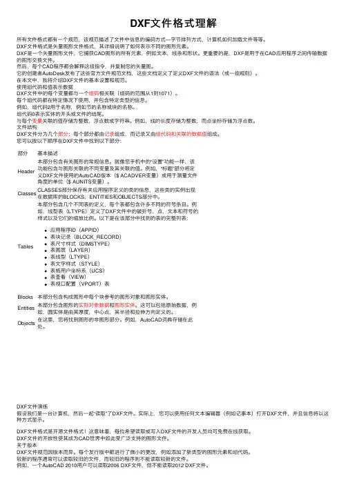
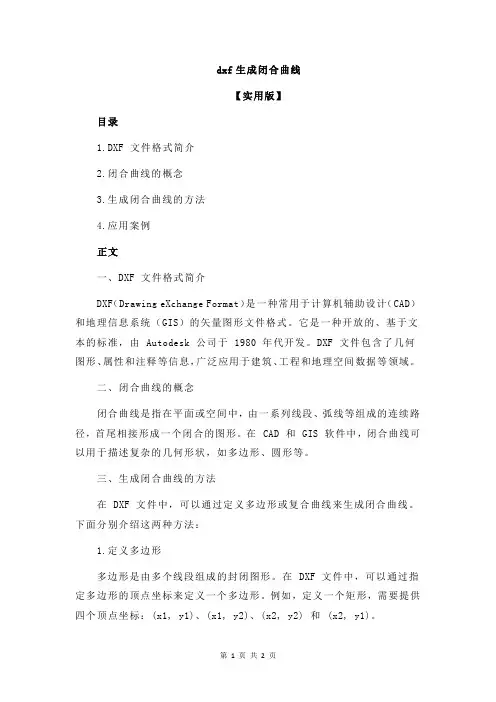
二、DXF文件数据格式分析图1.1为DXF文件数据格式的总体框图图2.1DXF数据格式框图由图1.1可知,DXF的数据格式有HEADER(标题段)、CLASSES(类段)、TABLES (表段)、BLOCKS(块段)、ENTITIES(实体段)、OBJECTS(对象段)、EOF(结束)。
出了这七个段之外还有一个THUMBNAILIMAGE段。
类/子类,组码,组值的格式如下:类/子类组码组值比如:AcDbCircle ARC的子类10 组码,起点的X坐标2860.382264303673 组值X的坐标为2860.382264303673组码比起类/子类以及组值有一个空格的缩进。
2.1 HEADER(标题段)DXF 文件的HEADER 段包含与图形关联的变量的设置。
它由AutoCAD 数据库版本号和一些系统变量组成。
每个变量由给出变量名称的组码9 指定,其后是提供变量值的组。
下面给出了HEADER段的一般格式。
0 HEADER 段的开始SECTION2HEADER9 变量名称标识符(仅在DXF 文件的HEADER 段中使用)为每个标题变量重复一次$<变量><组码><值>0 HEADER 段的结束ENDSEC2.2 CLASSES(类段)CLASSES 段。
一、DXF文件格式分析DXF文件由标题段、表段、块段、实体段和文件结束段5部分组成,其内容如下。
☆标题段(HEADER)标题段记录AutoCAD系统的所有标题变量的当前值或当前状态。
标题变量记录了AutoCAD系统的当前工作环境,如SNAP捕捉当前状态、栅格间距式样、当前图层层名及线型、颜色等。
☆表段(TABLES)表段共包含4个表,每个表又包含可变数目的表项。
这些表在文件中出现的顺序是线型表(LTYPE)、图层表(LAYER)、字样表(STYLE)、视图表(VIEW)。
☆块段(BLOCK)块段记录了所用块的块名,当前图层层名、块的种类、块的插入基点及组成该块的所有成员。
块的种类分为图形块、带有属性的块和无名块三种。
无名块包括用HATCH命令生成的剖面线和用DIM命令所完成的尺寸标准。
☆实体段(ENTITIES)实体段记录了每个实体的名称、所在图层及其名字、线型、颜色等。
☆文件结束段(EOF OF FILE)DXF文件的结束标志。
一个DXF文件由若干个组构成,每个组占两行,第一行为组的代码,第二行为组值。
组代码相当于数据类型的代码,它由CAD图形系统所规定,而组值为具体的数值,二者结合起来表示一个数据的含义和值。
例如,代码10代表一个点的X坐标,占一行,而其第二行4.5425则是点X坐标的具体数值,二者结合表示一点,其X坐标值为4.5425。
(1)组代码和组值的类型组代码为一个非负的不超过三位的整数,而组值由组代码的类型决定。
例如:代码0~9组值类型为字符型。
代码10~59组值类型为实型。
代码60~79组值类型为整型。
代码999表示解释行。
(2)组代码的含义每个组代码均有规定的含义,有些代码含义是固定的,而有些组代码则因应用场合不同而有多个含义,应具体分析。
另外,一些代码是备用的,目前版本尚未用到,现将他们的含义举例介绍如下。
0:表示一个事物的开始,如一个块、表、图层、实体等。
1:字符型数据的值,如TEXT的字符串、文件名、属性值等。
DXF文件简介目录1简介 (1)2文件结构 (2)3实体部分(ENTITIES) (3)1简介AutoCAD(Drawing Interchange Format或者Drawing Exchange Format) 绘图交换文件。
DXF 是Autodesk公司开发的用于AutoCAD与其它软件之间进行CAD数据交换的CAD 数据文件格式。
DXF是一种开放的矢量数据格式,可以分为两类:ASCII格式和二进制格式;ASCII具有可读性好,但占有空间较大;二进制格式占有空间小、读取速度快。
由于Autocad现在是最流行的cad系统,DXF也被广泛使用,成为事实上的标准。
绝大多数CAD 系统都能读入或输出DXF文件。
DXF文件是由很多的“代码”和“值”组成的“数据对”构造而成,这里的代码称为“组码”(group code),指定其后的值的类型和用途。
每个组码和值必须为单独的一行的。
DXF文件被组织成为多个“段”(section),每个段以组码“0”和字符串“SECTION”开头,紧接着是组码“2”和表示段名的字符串(如HEADER)。
段的中间,可以使用组码和值定义段中的元素。
段的结尾使用组码“0”和字符串“ENDSEC”来定义。
DXF-Drawing Exchange File(图形交换文件),这是一种ASCII文本文件,它包含对应的DWG文件的全部信息,不是ASCII码形式,可读性差,但用它形成图形速度快.不同类型的计算机(如PC及其兼容机与SUN工作站具体不同的CPU用总线)哪怕是用同一版本的文件,其DWG文件也是不可交换的. 为了克服这一缺点,AutoCAD提供了DXF类型文件,其内部为ASCII码,这样不同类型的计算机可通过交换DXF文件来达到交换图形的目的,由于DXF 文件可读性好,用户可方便地对它进行修改,编程,达到从外部图形进行编辑,修改的目的。
2文件结构ASCII 格式的DXF 可以用文本编辑器进行查看。
DXF结构解析以及坐标读取(非常清晰)DXF文件的结构很清楚,具体如下:1. 标题段(HEADER )有关图形的一般信息都可以DXF 文件的这一节找到,每一个参数具有一个变量名和一个相关值。
2. 表段这一段包含的指定项的定义,它包括:a、线形表(LTYPE)b、层表(LYER)c、字体表(STYLE)d、视图表(VIEW)e、用户坐标系统表(UCS)f、视窗配置表(VPORT)g、标注字体表(DIMSTYLE)h、申请符号表(APPID)3. 块段(BLOCKS)这一段含有块定义实体,这些实体描述了图形种组成每个块的实体。
4. 实体段(ENTITIES )这一段含有实体,包括任何块的调用。
5. END OF FILE(文件结束)下面是对DXF的基本结构举一实例进行说明:0 0 后接SECTIONSECTION 表明这是一个段的开始2 2 后接的是段名HEADER 说明该段是HEADER 段(标题段)9$ACADVER 文件是由AUTOCAD 产生的1AC10089 9 后接 $UCSORG$UCSORG 用户坐标系原点在世界坐标系中的坐标10 10 对应 X0.0 X 的值20 20 对应 Y0.0 Y 的值30 30 对应 Z0.0 Z 的值9$UCSXDIR 这是一段不太相关的部分,略去101.0... ....9 9 后接 $EXTMIN$EXTMIN 说明三维实体模型在世界坐标系中的最小值10 10 对应 X-163.925293 X 的值20 20 对应 Y-18.5415860.0 Y 的值30 30 对应 Z78.350945 Z 的值9 9 后接 $EXTMAN$EXTMAX 说明三维实体模型在世界坐标系中的最大值10 10 对应 X202.492279 X 的值20 20 对应 Y112.634300 Y 的值30 30 对应 Z169.945602 Z 的值0 0 后接 ENDSECENDSEC 说明这一段结束了0 0 后接SECTIONSECTION 表明这是一个段的开始2 2 后接的是段名TABLES 说明该段是TABLES 段(表段)... ... ... ... 该段对我们不太相关,此处略去不进行说明0 0 后接 ENDSECENDSEC 说明这一段结束了0 0 后接SECTIONSECTION 表明这是一个段的开始2 2 后接的是段名ENTITIES 说明该段是ENTITIES 段(实体段)这是我0 们要详细说明的段,该段包含了所有实体的POLYLINE 点的坐标和组成面的点序。