DongGuan SCMC DGP4 Pulp UHT-GEA-5.5bar
- 格式:pdf
- 大小:64.48 KB
- 文档页数:1

T1704DPET1504DPEP/No.: MANUAL DEL USUARIOLAVADORAFavor de leer este manual cuidadosamente antes de utilizar su lavadora y consérvelo para una referencia futura.El sensor detecta automáticamente la cantidad de detergente, temperatura ycalidad (dureza) del agua para efectuar el mejor programa de lavado yenjuague, resultando en el mejor programa de lavado.El Smart Drum con tipo de lavado de tambor es una cuba de lavadora máshigiénica y limpia que protege os tejidos y evita que se dañen.Un sensor de carga y un microprocesador en el controlador detectan la carga de lavado y fijan las condiciones óptimas de lavado, tales como nivel de agua, tiempo de lavado, etc. La tecnología más avanzada en sistema de control electrónico proporciona elmejor rendimiento de lavado.El motor avanzado BLDC gira directamente la tina sin la correa y elembrague, de tal modo que reduce el ruido de la lavadora.La lavadora ajusta la velocidad óptima según el tipo y carga de ropa.Se trata de una tecnologde servicio cuando existe un problema con la lavadora. Ofreceun servicio que da confianza a los clientes, mediante un anLa figura de las partes con puede ser diferente de la imagen de arriba según el modelo.artículos no hagan rasgones a otra ropa.No mezcle con detergente o blanqueador.Nunca vierta directamente el suavizante de tejido a la lavandería. Eso podrá provocar las manchas a la lavandería.No pare el lavado durante el primer centrifugado para la distribución a tiempo.El lavado de opción no está diseñado para ser usado con el distribuidor de suavizante de tejido.Scrud (Cera construida)Uso de suavizanteNunca verter blanqueador sin diluir directamente sobre las prendas o en la tina.Esto podría decolorar o dañar sus prendas.Nunca mezclar blanqueador con amoníaco o ácidos, como vinagre o removedor de ó mezcla de estas sustancias produce un gas tóxico que podría causar la muerte.Nunca verter blanqueador líquido dentro del despachador del blanqueador.Scrud es un nombre dado por la cera construida la cual puede presentarse en cualquier lavado cuando elNo use o mezcle el blanqueador líquido de cloro con otros químicos del uso doméstico tales como el líquido de limpieza del baño, eliminador de orín, ácido o los productos que contienen el amonio. Este tipo de mezclaje puede producir el humo peligroso el cual puede causar una lesión seria o la muerte.Para reducir el riesgo del incendio o las lesiones serias a las personas o a la propiedad, cumpla las advertencias básicas alistadas abajo :Lea y cumpla todas las instrucciones escritas en los productos de eliminar las manchas.Guarde los productos para eliminar las manchas dentro del contenedor original con la etiqueta y fuera del alcance de los niños.Solamente para el uso de lavado o de utensilios.No combine los productos para eliminar las manchas, en especial con el amonio y el blanqueador de cloro. Puede provocar el humo peligroso.Nunca lave los artículos que se han previamente limpiado, lavado, remojado o manchado por gasolina, solventes de limpieza en seco o otras substancias inflamables o explosivas porque ellos emiten vapores que pueden ser encendidos o explotados.Nunca use los solventes muy inflamables como gasolina dentro de casa. Los vapores pueden ser explotados teniendo contacto con las llamas o chispas.Para la eliminación exitosa de manchasElimine las manchas puntualmente.Determine el tipo de manchas, y luego siga el tratado recomendado en el cuadro abajo de instruccionespara eliminar las manchas.Para pre-tratar las manchas, use el producto de pre-lavado, detergente líquido, o una pasta hecha por eldetergente granulado y el agua.Use el agua fría para eliminar las manchas desconocidas porque el agua caliente puede fijar slidamente lasmanchas.Chequee las instrucciones de etiqueta al tratar las manchas para evitar el daño al tejido específico.Chequee el descoloramiento haciendo un test del eliminador de manchas a la costura interior.Enjuague y lave los artículos después de eliminar las manchas.• Los siguientes ajustes se indican cuando se presiona el botón :7 8 9 10 1 2 3 4 5 6 7Caliente Fría. respectivamente.Utilice este botón para ajustar la fuerza del chorro de agua.Si se pulsa este botón, Se efectuará un ciclo [Normal Intensa Suave Normal]La fuerza de la corrente de agua puede ajustarse en cualquier momento del lavado. Al proncipio Úsalo cuando quieras secar la tina vacía después de lavar.Para encender/cancelar(la función) mantén presionado el botón de lavado y enjuague simultáneamente.a medida que se oprima el boton.60 90 120 60• Presiona el botón por 3 segundos para seleccionar la función y presiona el botón de encendido para cancelarla.al presionar el botón, los programas se seleccionan como FUZZY(Normal)LANA LAVADO RÁPIDO JEANS LIMPIEZA INTELIGENTE SILENCIOSO FAVORITOLIMPIEZA TAMBOR FUZZY(Normal)* El sensor de cantidad de detergente detecta en base a detergente en polvo sintético. Si usted coloca detergente un ciclo de [3 4 5 ...12 14 16 ... 46 48 3]horas. Podrá establecerse un retardo máximo de 48 horas.detergente.n para aumentar el 111125455333222•Se indica la cantidadapropiada de detergentedetergente.•Se indica la cantidadapropiada de etergente allado del nivel de agua deinstrucciones de uso deldetergente.•Seleccione elJEANS•Seleccione el•Presione elcomor ropa interior y lana. Antes de•Cuando lave ropa de lana useun detergente suaverecomendado para lavarapropiado para el lavado. 1532•Seleccione elCierre la tapa.Finalización• El pulsador gira por 8 s para detectar la carga de lavado.• Luego se mostrar á el cantidad.• El agua sesuministrar á por ropa.• Cuando termina el programa de el éctrica se apague autom áticamente.356777666444764Orden de la distribuciCuando tu seleccionas PRE-SECADO por mas de 60 minutos 12) Mantener 2 kilos de ropa o menos cercior3) Seleccionar 60 minutos para una carga de algodCuando t1) El uso de esta funci2) Cuando tInstalación de la cubierta anti-roedores (opcional)La cubierta anti roedores debe ser fijada firmemente a la parte frontal de la lavadora.La especificaciones técnicas están suietas a cambios sin aviso previo.。
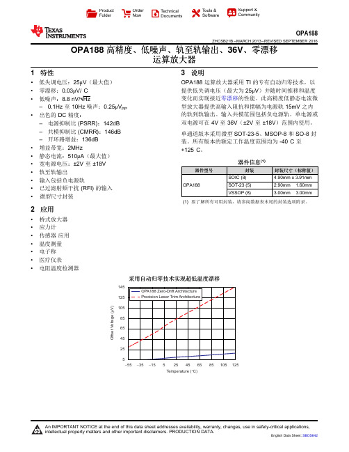
145125105856545255O f f s e t V o l t a g e (V )m -55-15525125Temperature (C)°-35456585105ProductFolder Order NowTechnical Documents Tools &SoftwareSupport &CommunityOPA188ZHCSB21B –MARCH 2013–REVISED SEPTEMBER 2016OPA188高精度、低噪声、轨至轨输出、36V 、零漂移运算放大器1特性•低失调电压:25μV (最大值)•零漂移:0.03μV/°C •低噪声:8.8nV/√Hz–0.1Hz 至10Hz 噪声:0.25μV PP •出色的DC 精度:–电源抑制比(PSRR);142dB –共模抑制比(CMRR):146dB –开环路增益:136dB •增益带宽:2MHz•静态电流:510μA (最大值)•宽电源电压:±2V 至±18V •轨至轨输出•输入包括负电源轨•已过滤射频干扰(RFI)的输入•微型尺寸封装2应用•桥式放大器•应力计•传感器应用•温度测量•电子称•医疗仪表•电阻温度检测器3说明OPA188运算放大器采用TI 的专有自动归零技术,以提供低失调电压(最大为25μV )并随时间推移和温度变化而实现接近零漂移的性能。
此高精度低静态电流微型放大器提供高输入阻抗和摆幅为电源轨15mV 之内的轨到轨输出。
输入共模范围包括负电源轨。
单电源或双电源可在4V 至36V (±2V 至±18V )范围内使用。
单通道版本采用微型SOT-23-5、MSOP-8和SO-8封装。
所有版本的额定工作温度范围均为-40°C 至+125°C 。
器件信息(1)器件型号封装封装尺寸(标称值)OPA188SOIC (8) 4.90mm x 3.91mm SOT-23(5) 2.90mm ×1.60mm VSSOP (8)3.00mm ×3.00mm(1)要了解所有可用封装,请参阅数据表末尾的封装选项附录。


+SP20B/SP20F/SP20X/SP20PProgrammer User ManualPublication Release Date: Dec 22, 2022Revision A3深圳硕飞科技有限公司Chapter1 Introduction1.1 Performance Characteristics ------------------------------------------------------------------------------------ 31.2 SP20 series programmer parameter table -------------------------------------------------------------------- 4 Chapter2 Programmer Hardware2.1 Product Overview ---------------------------------------------------------------------------------------------------- 52.2 Product Add-ons ------------------------------------------------------------------------------------------------------ 5 Chapter3 Quick To Use3.1 Preparation work ------------------------------------------------------------------------------------------------------63.2 Programming your chip --------------------------------------------------------------------------------------------63.3 Read chip data and programming new chip-------------------------------------------------------------------------83.4 I ndicator status in USB mode------------------------------------------------------------------------------------------9 Chapter 4 Standalone Programming4.1 Download standalone data --------------------------------------------------------------------------------------- 104.2 Standalone programming operation ---------------------------------------------------------------------------- 11Manual mode ---------------------------------------------------------------------------------------------------------- 12 Automatic control mode (control via ATE interface) -------------------------------------------------------- 124.3 Indicator status in standalone mode --------------------------------------------------------------------------- 12 Chapter 5 Programming in ISP mode5.1 Select ISP programming mode -------------------------------------------------------------------------------- 135.2 ISP interface definition --------------------------------------------------------------------------------------------- 135.3 Connect the target chip ------------------------------------------------------------------------------------------ 145.4 Select ISP power supply mode -------------------------------------------------------------------------------- 145.5 Programming operation -------------------------------------------------------------------------------------------- 14 Chapter 6 Programming in Multi-machine Mode6.1 Hardware connection of programmer ------------------------------------------------------------------------ 156.2 Programming operation ------------------------------------------------------------------------------------------ 16 Appendix 1FAQ ---------------------------------------------------------------------------------------------------------------------------- 17 Appendix 2Disclaimer -------------------------------------------------------------------------------------------------------------------- 18 Appendix 3Revision History ------------------------------------------------------------------------------------------------------------ 19Chapter 1 IntroductionSP20 series (SP20B/SP20F/ SP20X/SP20P) programmers are the latest highspeed mass production programmers for SPI FLASH launched by Shenzhen SFLY T echnology. It fully supports the high-speed programming of SPI NOR / NAND FLASH, I2C / MicroWire and other EEPROMs from domestic and foreign manufacturers.1.1 Performance CharacteristicsHardware features●USB Type-C communication interface, no need for external power supply when used in USB mode;●Support USB and standalone mode high-speed mass production programming;●The built-in large-capacity memory chip saves the engineering data for standalone programming, and multipleCRC data verification ensures that the programming data is absolutely accurate;●Replaceable 28-pin ZIF socket, which can be supported by conventional universal programming bases;●OLED display, visually display the current operating information of the programmer;●RGB three-color LED indicates the working status, and the buzzer can prompt the success and failure of theprogramming;●Support poor pin contact detection, effectively improve programming reliability;●Support ISP mode programming, which can support on-board programming of some chips;●Multiple programming startup methods: button startup, chip placement (intelligent detection chip placementand removal, automatic startup programming), ATE control (independent ATE control interface, providing accurate and reliable programming machine control signals such as BUSY, OK, NG, START, extensively support automatic programming equipment of various manufacturers);●Short circuit / overcurrent protection function can effectively protect the programmer or chip from accidentaldamage;●Programmable voltage design, adjustable range from 1.7V to 5.0V, can support 1.8V/2.5V/3V/3.3V/5V chips;●Provide equipment self-check function;●Small size (size: 108x76x21mm), simultaneous programming of multiple machines only takes up a very smallwork surface;Software features●Support Win7/Win8/Win10/Win11;●Support software upgrade to add new devices;●Support project file management (project file saves all programming parameters, including: chip model, datafile, programming settings, etc.);●Support the reading and writing of additional storage area (OTP area) and configuration area (status register,etc.) of the chip;●Support automatic recognition of 25 series SPI FLASH;●Automatic serial number function (can be used to generate product unique serial number, MAC address,Bluetooth ID, etc.,);●Support multi-programmer mode connection: one computer can be connected with 8 SP20 seriesprogrammers for simultaneous programming,The automatic serial number function is active in multi-programmer mode;●Support log file saving;Note:The above functions depend on the product model. For details, please refer to the product parameter table in section 1.21.2 SP20 series programmer parameter tableProduct parameter SP20P SP20X SP20FSP20B Product AppearanceSupported chip voltage range 1.8-5V 1.8-5V 1.8-5V 1.8-5V Support chip series (interface type)(①I2C EEPROM ②Microwire EEPROM③SPI Flash)①②③①②③①②③①②③Multi connection(One computer can connect 8 programmers)Y Y Y YMass production with USB(Auto detect the chip insert and remove, autoprogrammer)Y Y Y YAutomatic serial NO.(Serial numbers programming)Y Y Y Y RGB LEDs work indicator Y Y Y Y Buzzer prompt Y Y Y NStandalone programming(programming without computer, suitable for massproduction)Y Y Y NSupport automation equipment(Control the automatic equipment with ATE)Y Y N NISP programmer(Support some models)Using usb mode Y Y Y Yin stand-alone mode Y N N N Start button for programming Y N N N OLED display Y N N N Programmingspeed(Programming +verification)Full capacity dataGD25Q16(16Mb)6s 6s 6s 7sW25Q64JV(64Mb)25s 25s 25s 28sW25Q128FV(128Mb)47s 47s 47s 52s "Y" means it has or supports the function, "N" means it does not have or does not support the functionChapter 2 Programmer Hardware 2.1 Product OverviewItem Name Illustrate①28P ZIF socketInsert DIP packaged chip, programming socket②Three color indicator Blue: programming; green: successful programming; red: failedprogramming③OLED display Display current operating status and results(only SP20P has thiscomponent)④Programming start button Start programming by pressing the button(only SP20P has thiscomponent)⑤USB interface USB Type-C interface⑥ISP/ATE multiplexing interface● Provide programming machine control signals (BUSY, OK, NG,ST ART) (only SP20P and SP20X have this function)● ISP programming of the chip soldered on the circuit board2.2 Product Add-onsType-C data cable ISP cable 5V/1A power adapter Instruction manual②Chapter 3 Quick To UseThis chapter takes a piece of SOIC8 (208mil) packaged SPI FLASH chip W25Q32DW as an example to introducethe SP20P programmer's method of programming the chip in USB mode. The conventional programming includes the following 5 steps:3.1 Preparation work1) Install SP20 series programmer software (includes USB driver, the USB driver will be installed by default when installing the software), support Win7/Win8/Win10/Win11, software download URL: ;2) Connect the programmer to the USB port of the computer with a USB cable, and the green light of the programmer will be on when the connection is normal;3) Start the programmer software "SFLY SP20", the software will automatically connect to the programmer, and the right window of the software will display the programmer model and product serial number. If the connection fails: please check whether the USB cable is plugged in; check whether the USB driver is successfully installed in the computer device manager (if the USB driver is not installed correctly, please manually update the USB driver: locate the "USB_DRIVER" in the programmer software installation directory Folder, just update the driver);3.2 Programming your chip1)Select the chip model: Click the toolbar button, and search for the chip model to be programmed in the pop-up dialog boxfor selecting chip model: W25Q32DW. Select the matching chip brand, model and package type (selecting the wrong brand and model will result in programming failure).After the connection is successful, the currently connected programmer modeland sequence will be displayedConnect to the computer USB port2)Load file:Click the toolbar button to load the data file, which can support Bin and Hex formats.3) Operation option setup:Make the corresponding settings on the "Operation Options" page as needed. Tip: The non-empty chip must be erased.4)Place the chip:Raise the handle of the ZIF socket, insert the bottom row of the programming socket aligned with the bottom of the ZIF Socket, press down the handle, and then put the chip into the programming socket. Note that the direction of pin 1 of the chip should not be placed in the wrong direction. Tip: You can view the corresponding programming socket model and insertion method on the "chip information" page.5)Programming operation:Click the toolbar button to start programming:When the programming is completed, the status icon changes to "OK" to indicate that the programming is successful:3.3 Read chip data and programming new chip1)Follow the steps in section 3.2 to select the chip model, install the socket and the chip to be read;Tips:①You can automatically identify most SPI Flash chips through the "Check Model" button in the toolbar;②The pins of the desoldered chip need to be cleaned up to avoid poor contact;2) Click the read button in the toolbar, and the "Read Options" dialog box will pop up;click the "Save Data" button to save the read data to the computer for subsequent use;4) Close the "data buffer" and put in a new chip of the same model;5) Click the button to write the read content into the new chip.3.4 Indicator status in USB modeThe programmer has a RGB LED to indicate the working status:Indicator status State descriptionSteady blue Busy state, the programmer is performing operations such as erasing, programming, verification, etc.Flashing blue Wait for the chip to be put inSteady green Currently in standby mode, or the current chip is successfully programmedSteady red Chip programming failed (you can check the reason for the failure in the software information window)Chapter 4 Standalone ProgrammingSP20F,SP20X,SP20P support standalone (withourt computer) programming, suitable for mass production. The basic operation process is as follows:4.1 Download standalone data1) Connect the programmer to the computer USB port with a USB cable, and start the SP20 software;2) Follow the steps in section 3.2 to select the chip model, load the data file, and set the necessary operation options; 3) In order to ensure that the standalone data is correct, you can first programming a few chips and do the actual verification of the product; 4) Click the buttonto save the current project (hint: the saved project file, also called the project file, can beloaded and used later to avoid the trouble of repeated settings); 5) Click the buttonto download standalone data, and the "Download Project" dialog box will pop up;6) Click OK to download the standalone data to the programmer's built-in memoryTips: standalone data will not be lost after the programmer is powered off, and you can continue to use it next time.4.2 Standalone programming operationManual modeProgramming method of picking and placing chips manually. The manual operation steps in standalone mode are as follows:1) Download standalone data according to the method in section 4.1. Note that when downloading standalone data, select the startup control mode as "Chip Placement" (SP20P can also select "Key Start");2) Unplug the USB cable from the computer and connect it to the 5V power adapter. After the programmer is powered on, it will first check the internal standalone data to verify the integrity and accuracy of the data. This takes 3-25 seconds. If the test is passed, the indicator light flashes blue, indicating that the programmer has entered the standalone programming mode. If the test fails, the indicator shows a red flashing state, indicating that there is no valid standalone data in the programmer, and standalone programming cannot be started;Note: Only SP20P can display the working status of the programmer more intuitively through the OLED screen, as shown in the figure above, it prompts to wait for the chip to be inserted.3) Put the chip to be programmed on the ZIF socket, the indicator light changes from flashing blue to steady blue, indicating that the programmer has detected the chip and is programming;4)When the indicator light turns steady green, it means that the chip programming is completed and the programming is successful. If the indicator light turns red, it means that the current chip programming has failed. At the same time, the programmer waits for the current chip to be removed from the ZIF socket. If the buzzer prompt function is turned on, the programmer will beep when the programming is completed;5) Take out the chip and put it in the next chip, repeat this step until the programming is completed.Automatic control mode (control via ATE interface)SP20X/SP20P has an ISP/ATE multiplexing interface, which can be used with automatic programming machines and other automatic equipment to realize automatic programming (automatically pick and place chips, automatic programming). Proceed as follows:1) Download standalone data according to the method in section 4.1. Note that when downloading standalone data, select the start control mode as "ATE control (machine mode)". In this working mode, the ATE interface of the programmer can provide ST ART/OK/NG/BUSY indicator signal;2) Lead the chip pin line from the ZIF socket to the programming machine;3) Connect the machine control line to the programmer "ISP/ATE interface", the interface pins are defined as follows;4) Start programming.4.3 Indicator status in standalone modeThe programmer has a RGB LED to indicate the working status: Indicator status State description (manual method)State description(automatic control mode, only SP20X, SP20P) Flashing red The programmer did not download standalone dataThe programmer did not download standalone data Flashing blueWait for chip placement<No such status> Blue Programming chipProgramming chipGreen The chip programming is completed and the programming is successful (Waiting for chip removal) The chip programming is completed and the programming is successful RedChip programming failed (Waiting for chip removal)Chip programming failedChapter 5 Programming in ISP modeThe full name of ISP is In System Program. In ISP programming mode, you only need to connect a few signal lines to the relevant pins of the onboard chip to realize the read and write operations of the chip, which can avoid the trouble of desoldering the chip. SP20 has a 10P ISP/ATE multiplexing interface, the chips on the circuit board can be programmed through this interface.5.1 Select ISP programming modeSP20 series programmers can support ISP mode programming of some chips. Click the "chip model" button in the software to search for the chip model to be programmed, and select "ISP mode programming in the "Adapter/Programming Mode" column "(If there is no ISP mode programming in the searched chip programming method, it means that the chip can only be programmed with the programming socket). Refer to the picture below:5.2 ISP interface definitionThe ISP interface definition of SP20 series programmer is as follows:接口接口引脚图A 10P color ISP cable is randomly distributed to connect the ISP interface and the target board chip. The 5x2P plug is connected to the ISP interface of the programmer, and the other end is connected to the corresponding pin of the target chip through the DuPont header terminal.The corresponding relationship between the color of the ISP cable and the pins of the ISP interface is as follows:Colour Corresponding to ISPinterface pinsColour Corresponding to ISPinterface pinsBrown 1 Blue 6 Red 2 Purple 7 Orange (or pink)3 Grey 8 Yellow4 White 9 Green5Black105.3 Connect the target chipClick the "chip information" page on the main software interface to view the connection schematic diagram of the ISP interface and the target chip. Refer to the picture below:Different chips have different connection methods. Please click the "chip information" page in the software to view the detailed connection methods of the chip.5.4 Select ISP power supply modeDuring ISP programming, the target chip has two power options: powered by the programmer and self-powered by the target board. Set whether to check "Provide power to target board" on the "Project Settings" page of the software:Check "Provide power for target board", the programmer will provide power for the target board chip, please choose the power supply voltage according to the chip's rated working voltage. The programmer can provide a maximum load current of 250mA. If the load current is too large, the programmer will prompt over-current protection. Please uncheck "Provide power for the target board" and change to the target board's self-powered (SP20 programmer can support 1.65 V~5.5V target board operating voltage range, ISP signal driving voltage will automatically adjust with the target board's VCC voltage).5.5 Programming operationCheck that the hardware connection and software settings are correct, and click the button to complete the ISP programming of the chip.Chapter 6 Programming in Multi-machine ModeSP20 series programmer software supports simultaneous operation of up to 8 programmers connected to a computer (mass production or download standalone data).6.1 Hardware connection of programmer1) Use USB HUB to connect multiple programmers to the computer's USB port (USB hub must have an external power adapter, and an external power supply is required). Note that in multi-machine mode, only programmers of the same model can be used together, and different models cannot be mixed.2) Start the SP20 programmer software, the software will automatically connect to all connected programmers and enter the multi-machine mode. If the programmer software is already running, you can click Menu → Programmer →Reconnect, and the software will pop up the "Connect to the programmer" dialog box:multi-machine mode, and the interface is as follows:6.2 Programming operation1) The programming operation is the same as the programming procedure in section 3.2: select chip model → load file → set operation options → install programming socket;2)Click the button(Note: SP20P can choose two mass programming modes: "Chip Insert" and "Key Start". In this example, select the "Chip Insert" mode), and the programmer will wait for the chip to be placed;3) Put the programmed chips in the programming socket one by one, and the programmer will automatically start programming after detecting that the chips are put in. Each programmer works independently, programming in full asynchronous mode, no need to wait for synchronization. The software programming interface is as follows;4) Pick and place the chips according to the indicator status description in Section 3.4 or the prompts on the display screen to complete the entire mass of chip programming.Tips:SP20F,SP20X,SP20P support standalone programming. You can use the existing USB port on the computer to connect one or more programmers to download standalone data, and then use the standalone method for mass programming. Compared with the USB method, it is more convenient and more efficient. SP20B does not support standalone and can only be connected to a computer for mass programming.Appendix 1 FAQCan the programmer support img files?● The programmer software supports binary and hexadecimal file encoding formats. The conventional suffixof binary files is *.bin, and the conventional suffix of hexadecimal files is *.hex;● img is just a file suffix, and does not represent the file encoding format. Normally (above 90%) such filesare binary encoded. Just load it directly in the software, the software will automatically recognize whether the file is binary code, and load it in the recognized format;● T o ensure the accuracy of file loading, we recommend that users check the buffer checksum and filechecksum with engineer (or file code providers/customers) after loading such files. (These information will be displayed at the bottom of the main window of the writer software.)What are the common reasons for programming failure (including erasing failure/programming failure/verification failure/ID error, etc.)?● The chip manufacturer/model selected in the software does not match the actual chip;● The chip is placed in the wrong direction, or the programming socket is inserted in the wrong position.Please check the correct placement method through the "Chip Information" window of the software;● Poor contact between the chip pins and the programming socket;● Connect chips that have been soldered on other circuit boards by wires or IC programming clips, which maycause programming failure due to circuit interference. Please put the chips back into the programming socket for programming;● The chip may be damaged, replace with a new chip for testing.Why does the 24 series chip have no erase function?● The chip is based on EEPROM technology, the chip data can be directly rewritten without pre-erasing, sothere is no erasing operation available;● If you need to clear the chip data, please write FFH data directly to the chip.How to upgrade the programmer software and firmware?● Click the programmer software menu: Help-Check for updates. If there is an update, an update wizard willpop up. Please follow the prompts to download the upgrade package and install it;● Enter the download center of Sfly official website (), download the latest programmersoftware and install it;● Only need to upgrade the programmer software, no need to upgrade the programmer firmware.What should I do if there is no chip model in the programmer software?● First upgrade the programmer software to the latest version;● If there is no chip model to be programmed in the latest version of the software, please send an email toapply for addition. Indicate the following information: programmer model, chip brand to be added, detailed chip model, package (reminder: SP20 series programmers can only support SPI NOR FLASH, EEPROM, other types of chips cannot be supported).Appendix 2 DisclaimerShenzhen Sfly T echnology Co., Ltd. does its utmost to ensure the correctness of the product and its related software and materials. For possible product (including software and related materials) defects and errors, the company will do its best to solve the problem with its commercial and technical capabilities. The company is not responsible for all kinds of incidental, inevitable, direct, indirect, special, extended or punitive damages arising from the use or sale of this product, including but not limited to the loss of profit, goodwill, availability, Business interruption, data loss, etc., shall not be liable for any direct, indirect, incidental, special, derivative, punitive damages and third-party claims.Appendix 3 Revision History Release date Version Revised by Illustrate 2022-12-22 A3Sauwa Correction of a few errors2022-01-04 A2 Sauwa Updated the schematic in section 5.3 2021-12-11 A1 LYX First edition。

S698P4-DKitS698P4四核并行处理器应用开发系统使用说明书版本:V3.0珠海欧比特宇航科技股份有限公司地址:广东省珠海市唐家东岸白沙路1号欧比特科技园邮编:519080电话*************传真*************网址:前言感谢您选择了珠海欧比特宇航科技股份有限公司的产品:S698P4四核并行处理器应用开发系统,型号S698P4-DKit。
为了使您能尽快熟练地使用本产品,我们随产品配备了内容详细的使用说明书,在您第一次安装和使用本系统时,请务必仔细阅读随产品配备光盘里的相关资料。
本用户手册中如有错误和疏漏之处,热切欢迎您的指正。
使用注意事项为防止损坏此验证开发系统,非专业人员请勿自行拆装。
使用前,请先确认电源适配器输出电压为+5V,供电电流2A。
拨插设备时务必请先断电后再操作。
存放地点应具备以下条件:防雨、防潮;机械振动要小,防止可能的碰撞;温度:0℃~40℃;湿度:40% ~80%。
安全防范S698P4-DKit内部的电子部件可能会被静电损坏,为保证设备的安全,当接触这些部件时,请先确保人体没有静电。
为了保证操作人员和设备的安全,请仔细阅读该说明书并严格按照安全规则操作。
对于用户违反操作规则而造成的一切损失和用户擅自拆装而造成的仪表损坏,本公司将不承担责任。
若出现故障,请及时通知我们,并请提供产品的完整型号、出厂编号、故障现象、使用环境等详细资料,以便我们迅速为您排除故障。
声明制造商的责任只有在下列情况下,珠海欧比特宇航科技股份有限公司才认为应对仪器的安全、可靠性和性能的有关问题负责:装配、扩充、重新调整、改进或维修均由公司认可的人员进行操作;设备的使用按操作要求进行。
目录第一章简介 (1)1.1概述 (1)1.2缩略语 (1)1.3参考资料 (1)第二章S698P4-DKIT外观及配件 (2)2.1产品外观实物图 (2)2.2资源接口 (3)2.3配件清单 (4)2.4光盘内容 (4)第三章系统概述 (6)3.1功能特点 (6)3.1界面说明 (8)3.2.1 启动界面说明 (8)3.2.2 联机界面说明 (8)3.2.3 主界面说明 (9)3.2.4 三色灯界面说明 (9)3.2.5 数码管界面说明 (10)3.2.6 TFT界面说明 (10)3.2.7 以太网界面说明 (11)3.2.8 SD卡界面说明 (12)3.2.9 USB界面说明 (13)第四章应用及配置 (15)4.1开发步骤 (15)4.2模块应用及设置 (16)4.2.1 FLASH (16)4.2.2 SRAM (17)4.2.3 SDRAM (17)4.2.4 RS-232 / DSU串口 (18)4.2.5 CAN总线接口 (18)4.2.6 以太网接口 (18)4.2.8 8路GPIO接口 (19)4.2.9 USB接口 (19)4.2.10 8位数码管 (19)4.2.11 SD 接口 (19)4.2.12 STN屏接口 (19)4.2.13 TFT屏接口 (20)4.3软件调试 (20)4.4FLASH烧写 (26)4.4.1 生成 .bin文件 (26)4.4.2 烧写FLASH (27)第五章硬件跳线设置、外围接口及其管脚定义 (35)5.1硬件跳线设置 (35)表5-1SDRAM连接器(U401)信号定义 (36)表5-2:UART/DSU串口信号定义 (37)表5-3:CAN总线接口信号定义 (38)表5-4:RJ45网口信号定义 (39)表5-6:SD接口信号定义 (39)表5-7:USB接口(P901)信号定义 (40)表5-8:STN屏接口(P801)信号定义 (40)表5-9:TFT(U1104)信号定义 (40)表5-10:扩展槽接口信号定义 (41)附录A 产品装箱清单 (43)第一章简介1.1概述S698P4-DKit主要是为了使应用S698P4四核芯片的用户快速掌握关于S698P4芯片的外围电路设计,缩短项目的研发周期。
GP1266 SIP电话使用手册目录1.产品介绍 (4)2.规格与特性 (4)2.1.硬件特性 (4)2.2.软件特性 (5)2.3.协议、标准 (6)2.4.电器指标 (6)2.5.外形尺寸 (7)2.6.使用环境 (7)3.安装 (7)3.1.包装物品清单 (7)3.2.连接电话 (8)4.GP1266话机外形 (8)4.1.按键示意 (8)4.2.按键功能说明 (9)4.3.LED指示灯功能说明 (10)5.配置指南 (10)5.1.使用电话按键配置话机 (10)5.1.1.键盘操作 (10)5.1.2.查看当前系统信息 (12)5.1.3.网络设置 (12)5.1.4.语音设置 (13)5.1.5.协议设置 (13)5.1.6.呼叫设置 (14)5.1.7.系统设置 (15)5.2.通过Web页面配置话机 (15)5.2.1.网络设置 (16)5.2.2.语音设置 (18)5.2.3.基本协议设置 (19)5.2.4.高级协议设置 (20)5.2.5.呼叫设置 (21)5.2.6.系统设置 (23)5.2.7.设置电话簿 (24)5.2.8.设置拨号规则 (25)6.基本操作 (26)6.1.呼叫 (26)6.1.1.摘机/挂机/免提状态切换 (26)6.1.2.直接拨号 (26)6.1.3.重拨 (27)6.1.4.查询通话记录拨号 (27)6.1.5.查询电话本拨号 (27)6.1.6.快速拨号 (27)6.2.接听 (28)6.2.1.接听来电 (28)6.2.2.呼叫保持 (28)6.2.3.接听等待中的来电 (28)6.2.4.恢复接听 (28)6.3.呼叫转接 (Transfer) (28)6.3.1.呼叫前转(Blind Transfer) (29)6.3.2.呼叫后转(Attend Transfer) (29)6.4.呼叫转移(Forward) (29)6.4.1.呼叫转移号码 (29)6.4.2.无条件转移 (30)6.4.3.遇忙转移 (30)6.4.4.无应答转移 (30)6.5.自动应答 (30)6.6.静音 (30)6.7.免打扰 (31)6.8.查看留言 (31)6.8.保存及删除通话记录 (31)6.9.维护电话本 (32)6.9.1.保存电话本 (32)6.9.2.增加电话本条目 (32)6.9.3.修改电话本条目 (33)6.9.4.删除特定电话本条目 (33)6.9.5.删除所有电话本条目 (34)7.软件升级 (34)7.1手工升级 (34)7.1.1.选定升级类别 (35)7.1.2.定位升级文件 (35)7.1.3.开始升级 (35)8.恢复与保存出厂设置 (35)8.1恢复出厂设置 (35)8.2保存出厂设置 (36)1. 产品介绍IP 是网际互联网协议(Internet Protocol)的简称,IP 电话是利用IP协议的分组数据包进行语音的传送。
Eaton 207466Eaton Moeller® series DILP Contactor, 4 pole, 630 A, 2 N/O, 2 NC,220 V 50 Hz, 230 V 50 Hz, AC operation, Screw terminalsEspecificaciones generalesEaton Moeller® series DILP 4-polecontactor2074664015082074661272 mm225 mm270 mm17.2 kgCEULVDE 0660CSA File No.: LR72236UL File No.: E29096IEC/EN 60947IEC/EN 60947-4-1UL 508CSAUL Category Control No.: NLDX CSA-C22.2 No. 14-05DILP630/22(220-230V50HZ)Product Name Catalog NumberEANProduct Length/Depth Product Height Product Width Product Weight Certifications Model Code630 AIs the panel builder's responsibility. The specifications for the switchgear must be observed.200 kW0 kW220 V400 AMeets the product standard's requirements.470 A0 kWMeets the product standard's requirements.5000 A230 V5000 A550 A70 °CRail connection eaton-contactors-dilp-dimensions-003.epseaton-contactors-complete-unit-dilp-3d-drawing.eps eaton-manual-motor-starters-contactor-dilp-3d-drawing.epsDA-CE-ETN.DILP630_22(220-230V50HZ)eaton-contactors-complete-unit-dilp-wiring-diagram.epsIL03407021Zdilp500.dwgdilp500.stpRated operational current for specified heat dissipation (In) 10.11 Short-circuit ratingRated operational power at AC-3, 380/400 V, 50 Hz Rated operational power at AC-4, 380/400 V, 50 Hz Rated control supply voltage (Us) at AC, 50 Hz - min Conventional thermal current ith at 60°C (3-pole, open) 10.4 Clearances and creepage distancesNumber of contacts (normally closed) as main contact Conventional thermal current ith at 55°C (3-pole, open) Rated operational power (NEMA)10.2.3.1 Verification of thermal stability of enclosures Rated breaking capacity at 380/400 VRated control supply voltage (Us) at AC, 50 Hz - max Rated breaking capacity at 660/690 VRated operational current (Ie) at DC-1, 220 VAmbient operating temperature - maxElectrical connection type of main circuit DibujoseCAD model Esquemas eléctricos Instrucciones de montaje mCAD modelNumber Of PolesFour-poleAmbient operating temperature - min-40 °C10.6 Incorporation of switching devices and components Does not apply, since the entire switchgear needs to be evaluated.10.2.6 Mechanical impactDoes not apply, since the entire switchgear needs to be evaluated.10.3 Degree of protection of assembliesDoes not apply, since the entire switchgear needs to be evaluated.ApplicationContactors for 4 pole electric consumersOperating frequency3600 mechanical Operations/h (AC operated)Voltage typeACShort-circuit protection rating (type 1 coordination) at 400 V 630 A gG/gLProduct categoryContactorsRated operational power at AC-3, 690 V, 50 Hz355 kWPower consumption, pick-up, 50 Hz3500 VA, Dual-frequency coil in a cold state and 1.0 x UsHeat dissipation capacity Pdiss0 WSwitching time (AC operated, make contacts, opening delay) - min10 msRated operational power at AC-3, 240 V, 50 Hz110 kWRated operational power at AC-3, 1000 V, 50 Hz220 kW10.9.2 Power-frequency electric strengthIs the panel builder's responsibility.Degree of protectionIP00Overvoltage categoryIIISwitching time (AC operated, make contacts, opening delay) - max20 msPollution degree3Rated operational current (Ie) at AC-1, 380 V, 400 V, 415 V630 APower consumption, pick-up, 60 Hz3500 VA, Dual-frequency coil in a cold state and 1.0 x UsSwitching time (AC operated, make contacts, closing delay) - max60 msRated impulse withstand voltage (Uimp)8000 V ACConnectionScrew terminalsTightening torque12 - 16 Nm, Main cable connection screw/bolt1.2 Nm, Screw terminals, Control circuit cablesRated operational current (Ie) at AC-3, 660 V, 690 V370 A10.2.2 Corrosion resistanceMeets the product standard's requirements.10.2.4 Resistance to ultra-violet (UV) radiationMeets the product standard's requirements.10.2.7 InscriptionsMeets the product standard's requirements.Rated operational current (Ie) at AC-3, 380 V, 400 V, 415 V400 ANumber of contacts (normally open contacts)2Switching time (AC operated, make contacts, closing delay) - min 30 msShort-circuit protection rating (type 2 coordination) at 400 V630 A gG/gLNumber of auxiliary contacts (normally open contacts)2Shock resistance10 g, N/O main contact, Mechanical, according to IEC/EN 60068-2-27, Half-sinusoidal shock 10 msRated operational current (Ie) at AC-3, 1000 V155 ARated operational current (Ie) at DC-1, 110 V550 APower consumption, sealing, 60 Hz60 W, Dual-frequency coil in a cold state and 1.0 x Us140 VA, Dual-frequency coil in a cold state and 1.0 x Us, at 60 Hz10.12 Electromagnetic compatibilityIs the panel builder's responsibility. The specifications for the switchgear must be observed.10.2.5 LiftingDoes not apply, since the entire switchgear needs to be evaluated.Rated control supply voltage (Us) at DC - min0 V10.8 Connections for external conductorsIs the panel builder's responsibility.Number of main contacts (normally open contact)4Rated breaking capacity at 220/230 V5000 AScrew sizeM3.5, Terminal screw, Control circuit cablesM10, Terminal screw, Main cablesRated operational current (Ie) at AC-4, 400 V0 AProtectionFinger and back-of-hand proof with terminal shroud, Protection against direct contact when actuated from front (EN 50274)Power consumption, sealing, 50 Hz60 W, Dual-frequency coil in a cold state and 1.0 x UsRated operational power at AC-3, 440 V, 50 Hz200 kWTerminal capacity (stranded)2 x (35 - 185) mm², Main cables1 x (70 - 300) mm², Main cablesRated breaking capacity at 500 V5000 ARated operational power at AC-3, 415 V, 50 Hz200 kWClimatic proofingDamp heat, cyclic, to IEC 60068-2-30Static heat dissipation, non-current-dependent Pvs60 WRated control supply voltage (Us) at DC - max0 V10.9.3 Impulse withstand voltageIs the panel builder's responsibility.Utilization categoryAC-1: Non-inductive or slightly inductive loads, resistance furnacesRated operational current (Ie) at AC-3, 440 V400 A10.5 Protection against electric shockDoes not apply, since the entire switchgear needs to be evaluated.Safe isolation1000 V AC, Between coil and contacts, According to EN 61140 690 V AC, Between the contacts, According to EN 6114010.13 Mechanical functionThe device meets the requirements, provided the information in the instruction leaflet (IL) is observed.10.9.4 Testing of enclosures made of insulating materialIs the panel builder's responsibility.Number of contacts (normally closed contacts)2Heat dissipation per pole, current-dependent Pvid46 WActuating voltage220 V 50 HzEquipment heat dissipation, current-dependent Pvid0 WRated operational current (Ie)450 A at DC-5, 110 V450 A at DC-3, 110 V450 A at DC-5, 220 V450 A at DC-3, 60 V450 A at DC-3, 220 V450 A at DC-5, 60 VPick-up voltage0.85 - 1.1 V AC x UcConventional thermal current ith at 40°C (3-pole, open)630 ATerminal capacity (solid)2 x (0.5 - 2.5) mm², Control circuit cables2 x (35 - 185) mm², Main cables1 x (70 - 300) mm², Main cablesNumber of auxiliary contacts (normally closed contacts)2Rated operational current (Ie) at DC-3/DC-5 at 440 V450 A10.2.3.2 Verification of resistance of insulating materials to normal heatMeets the product standard's requirements.10.2.3.3 Resist. of insul. mat. to abnormal heat/fire by internal elect. effectsMeets the product standard's requirements.Lifespan, mechanical5,000,000 Operations (AC operated)Rated making capacity up to 690 V (cos phi to IEC/EN 60947) 5000 ARated operational current (Ie) at DC-1, 440 V450 ARated operational current (Ie) at DC-1, 60 V550 ARated operational voltage (Ue) at AC - max1000 VRated control supply voltage (Us) at AC, 60 Hz - min0 VEaton Corporation plc Eaton House30 Pembroke Road Dublin 4, Ireland © 2023 Eaton. All Rights Reserved. Eaton is a registered trademark.All other trademarks areproperty of their respectiveowners./socialmediaIs the panel builder's responsibility.The panel builder is responsible for the temperature rise calculation. Eaton will provide heat dissipation data for the devices.370 A2, Terminal screw, Control circuit cables, Pozidriv screwdriver 100 %400 A1760 A0 V1000 V10.7 Internal electrical circuits and connections 10.10 Temperature riseRated operational current (Ie) at AC-3, 500 V Screwdriver sizeDuty factor Rated operational current (Ie) at AC-3, 220 V, 230 V, 240 V Conventional thermal current ith of main contacts (1-pole, open)Rated control supply voltage (Us) at AC, 60 Hz - max Rated insulation voltage (Ui)。
The Alphacool Core Flat Reservoir not only looks sleek with its aRGBlighting, but also offers flexibility with a total of 5 connections. Thereservoir and pump top are both made entirely of acrylic, makingmaintenance and monitoring of the water loop significantly easier and giving the reservoir a unique design. The installation of a D5 or VPPpump is required for operation. Due to its flat design, the Core FlatReservoir also fits in small cases.•Easy filling, draining and venting possible •Transparent Reservoir •Brilliant digital aRGB illumination •Compatible with VPP/D5 pumps- Can be mounted on the radiator or panel V. 1.003 // 11.2023Alphacool Core Flat Reservoir 360 Left D5/VPPAlphacool article number: 154861x Core Flat Reservoir 360 Left 1x Allen Key4x M4x22 Pump Screw 6x Core Push Mount Set 4x G1/4 Plug1x ARGB AdapterThe Alphacool Core Flat Reservoir not only looks sleek with its aRGB lighting, but also offers flexibility with a total of 5 connections. The reservoir and pump top are both made entirely of acrylic, making maintenance and monitoring of the water loop significantly easier and giving the reservoir a unique design. The installation of a D5 or VPP pump is required for operation. Due to its flat design, the Core Flat Reservoir also fits in small cases.Core DesignA key element of Alphacool's Core Design series are the chrome-plated G1/4" connections made of brass. In the Core Flat Reservoir, the connections are recessed rather than screwed into a thread, bypassing the problem of possible leaks due to cracking from the direct screwing of the connections into the acrylic. The connections are in two parts, fitted with an O-ring and counter each other when mounted in the acrylic. This not only ensures absolute sealing of each connection, but also allows for the clear and functional appearance of the Alphacool Core Design series.Easy installationWith the included Core Push Mounting kit, the Core Flat Reservoir can be mounted on the case panel or on a radiator. The metal pins are attached to the radiator or case panel and the matching female sleeves are attached to the Flat Reservoir (see manual). I n the next installation step, the Flat Reservoir is simply and tool-free pushed onto the pins. Alphacool's Push-Mounting allows for a secure fit of the reservoir on the case panel or on the radiator and allows for easy disassembly for maintenance or expansion projects.GamechangerThe Core Flat Reservoir is offered as a 240mm or 360mm version, with left positioning of the pump top. This makes the reservoir ideal for custom water loops. An additional drain port is located on the side, allowing for easy and uncomplicated draining of the Flat Reservoir.High-quality material selection & brilliant lightingAlphacool's Core Flat Reservoir is made of high-quality acrylic glass, allowing for an unobstructed view of the coolant and brilliant illumination by the built-in digital addressable aRGB LEDs. The lighting can be controlled via a digital aRGB header on the motherboard or optionally through Alphacool's Aurora Eiscontrol aRGB controller (item number: 15360).Drawing。
EPSONP R O D U C T I N F O R M A T I O N G U I D EUPDATE FOR BUSINESS SYSTEM PRODUCTS7/09This package provides a scanner product section to be added to the Epson Business System Product Information Guide. The table of contents of this section is listed below.Epson CaptureOne Single FeedAccessories . . . . . . . . . . . . . . . . . . . . . . . . . . . . . . . . . . . . . . . . . . . . . . . . . . . . . . . . . . . . . . . . . . . . . . . . . 1 Connections . . . . . . . . . . . . . . . . . . . . . . . . . . . . . . . . . . . . . . . . . . . . . . . . . . . . . . . . . . . . . . . . . . . . . 1 Specifications . . . . . . . . . . . . . . . . . . . . . . . . . . . . . . . . . . . . . . . . . . . . . . . . . . . . . . . . . . . . . . . . . . . . . . . 1 Computer requirements . . . . . . . . . . . . . . . . . . . . . . . . . . . . . . . . . . . . . . . . . . . . . . . . . . . . . . . . . . . 1 Scanning specifications . . . . . . . . . . . . . . . . . . . . . . . . . . . . . . . . . . . . . . . . . . . . . . . . . . . . . . . . . . . 1 Paper specifications . . . . . . . . . . . . . . . . . . . . . . . . . . . . . . . . . . . . . . . . . . . . . . . . . . . . . . . . . . . . . . 1 MICR specifications . . . . . . . . . . . . . . . . . . . . . . . . . . . . . . . . . . . . . . . . . . . . . . . . . . . . . . . . . . . . . . . 1 Electronic endorsement . . . . . . . . . . . . . . . . . . . . . . . . . . . . . . . . . . . . . . . . . . . . . . . . . . . . . . . . . . . 2 Reliability . . . . . . . . . . . . . . . . . . . . . . . . . . . . . . . . . . . . . . . . . . . . . . . . . . . . . . . . . . . . . . . . . . . . . . . . . . . 2 Electrical Characteristics . . . . . . . . . . . . . . . . . . . . . . . . . . . . . . . . . . . . . . . . . . . . . . . . . . . . . . . . . . . . . . 2 Safety . . . . . . . . . . . . . . . . . . . . . . . . . . . . . . . . . . . . . . . . . . . . . . . . . . . . . . . . . . . . . . . . . . . . . . . . . . . . . . 2 Environmental Conditions . . . . . . . . . . . . . . . . . . . . . . . . . . . . . . . . . . . . . . . . . . . . . . . . . . . . . . . . . . . . . 2 DIP Switches . . . . . . . . . . . . . . . . . . . . . . . . . . . . . . . . . . . . . . . . . . . . . . . . . . . . . . . . . . . . . . . . . . . . . . . . 2 Lights and Switches . . . . . . . . . . . . . . . . . . . . . . . . . . . . . . . . . . . . . . . . . . . . . . . . . . . . . . . . . . . . . . . . . . 2 LEDs . . . . . . . . . . . . . . . . . . . . . . . . . . . . . . . . . . . . . . . . . . . . . . . . . . . . . . . . . . . . . . . . . . . . . . . . . . . . 2 Switches . . . . . . . . . . . . . . . . . . . . . . . . . . . . . . . . . . . . . . . . . . . . . . . . . . . . . . . . . . . . . . . . . . . . . . . . 2 Inserting a Check . . . . . . . . . . . . . . . . . . . . . . . . . . . . . . . . . . . . . . . . . . . . . . . . . . . . . . . . . . . . . . . . . . . . 2 Ejecting Checks . . . . . . . . . . . . . . . . . . . . . . . . . . . . . . . . . . . . . . . . . . . . . . . . . . . . . . . . . . . . . . . . . . . . . 3 Installing the Franking Cartridge . . . . . . . . . . . . . . . . . . . . . . . . . . . . . . . . . . . . . . . . . . . . . . . . . . . . . . . . 3 Single Pass Check Flow . . . . . . . . . . . . . . . . . . . . . . . . . . . . . . . . . . . . . . . . . . . . . . . . . . . . . . . . . . . . . . . 3 Cleaning the Scanner Glass . . . . . . . . . . . . . . . . . . . . . . . . . . . . . . . . . . . . . . . . . . . . . . . . . . . . . . . . . . . 4 Cleaning the MICR Unit . . . . . . . . . . . . . . . . . . . . . . . . . . . . . . . . . . . . . . . . . . . . . . . . . . . . . . . . . . . . . . . 4 Clearing a Paper Jam . . . . . . . . . . . . . . . . . . . . . . . . . . . . . . . . . . . . . . . . . . . . . . . . . . . . . . . . . . . . . . . . 4 Transporting the Scanner . . . . . . . . . . . . . . . . . . . . . . . . . . . . . . . . . . . . . . . . . . . . . . . . . . . . . . . . . . . . . . 4 Self-test . . . . . . . . . . . . . . . . . . . . . . . . . . . . . . . . . . . . . . . . . . . . . . . . . . . . . . . . . . . . . . . . . . . . . . . . . . . . . 4 Scanner Dimensions and Weight . . . . . . . . . . . . . . . . . . . . . . . . . . . . . . . . . . . . . . . . . . . . . . . . . . . . . . . 4 Error and Information Codes . . . . . . . . . . . . . . . . . . . . . . . . . . . . . . . . . . . . . . . . . . . . . . . . . . . . . . . . . . . 5 Status messages . . . . . . . . . . . . . . . . . . . . . . . . . . . . . . . . . . . . . . . . . . . . . . . . . . . . . . . . . . . . . . . . . . 5 Recoverable errors . . . . . . . . . . . . . . . . . . . . . . . . . . . . . . . . . . . . . . . . . . . . . . . . . . . . . . . . . . . . . . . 5 Unrecoverable errors . . . . . . . . . . . . . . . . . . . . . . . . . . . . . . . . . . . . . . . . . . . . . . . . . . . . . . . . . . . . . . 5 Sensors . . . . . . . . . . . . . . . . . . . . . . . . . . . . . . . . . . . . . . . . . . . . . . . . . . . . . . . . . . . . . . . . . . . . . . . . . . . . . 5 Related Documentation . . . . . . . . . . . . . . . . . . . . . . . . . . . . . . . . . . . . . . . . . . . . . . . . . . . . . . . . . . . . . . 57/09Epson CaptureOne Single Feed7/09Epson CaptureOne Single Feed - 1AccessoriesConnectionsSpecificationsComputer requirementsCPU Pentium 4 1.2 GHz or aboveMemory ≥ 256MB above minimum OS system requirementsHDD space ≥ 30MB free space with driver installed InterfaceUSB 2.0 high-speedWindows version 2000 Professional SP4XP Home Edition/ Professional SP2/SP3Vista (32-bit, 64-bit) Home Basic/ Home Premium/ Ultimate/ BusinessVista (32-bit, 64-bit) Home Basic/ Home Premium/ Ultimate/ Business with SP1.NET framework 1.1, 2.0, 3.0, or 3.5Supported development languagesWin32Visual C ++ 6.0, Visual Basic Visual C ++ .NET 2003,Visual C ++ 2005, Visual C #.NET 2003, Visual C # 2005,Visual Basic .NET 2003, Visual Basic 2005Scanning specificationsSingle passScans both sides of check, reads MICR, and performs franking in same pass.Scanner type CIS (contact image scanner)Resolution (dpi)200 x 200, 120 x 120, 100 x 100Graduation Grayscale:256 levelsBlack & white: 2 valuesData formats Grayscale:TIFF, JPEG, BMP, RAWBlack & white:TIFF (CCITT Group 4),BMPImage size 4.04 (W) x 10.59" (L) (maximum){102.6 x 269 mm}Image quality Complies with IQA (Image QualityAssurance) by FSTC (Financial Services Technology Consortium)Scanning speed 19.69 "/s {500 mm/s}Font recognition OCR A and OCR BOCR recognition ≥ 98% at 77°F (ANSI, excluding O and 0)Paper specificationsTypeNormal, single-ply only Size (H x L)2.68 ~ 4.72" x 4.72 ~ 9.25"{68 ~ 120 mm x 120 ~ 235 mm}Thickness 0.003 ~ 0.008" {0.075 ~ 0.2 mm}Weight 16 ~ 32 lb {60 ~ 120 g/m 2}SF capacity Holds 1 sheetMain pocket capacity (both 1- and 2-pocket models)Holds up to 100 sheetsSub pocket capacity (2-pocket model only)Holds up to 50 sheetsInstallation Must be horizontal (within a tilt of ± 5°)MICR specificationsMagnetic character typesE13B, CMC7 (Alphabetic not supported)MICR recognition rate≥ 98% at 77°F (E13B: ANSI)Errors of ≤ 1% (E13B: ANSI)Franking cartridge EFC-01 franking cartridgeInk color: redExpiration:18 months from production(at room temperature)Ink life:18,000 prints** Using Epson’s standard print pattern.Contents of the Utility & Documents CD TM-S1000 Single Feed Driver TM-S1000 Single Feed UtilityTM-S1000 Single Feed Utility User’s Manual TM-S1000 Single Feed User’s ManualConnector Description USB 2.0High-speed transmission at 480 Mbps [bps: bits per second]PowerAC Adapter C, 24 V ± 10%, supplied with CaptureOneUSB connectorPower supply connectorHook to secure USB cableEpson CaptureOne Single Feed Single Feed2 - Epson CaptureOne Single Feed 7/09Electronic endorsementCan paste recorded image data on the back image of a check.ReliabilityFranking cartridge life18,000 in Epson standard print patternFranking cartridge expiration date18 months after productionScanner life span 1 million sheets MTBF 180,000 hours MCBF 2,470,000 cyclesElectrical CharacteristicsPower supply Epson AC Adapter C supplied with scanner Supply voltage 24 V ± 10%Current consumption Operation 1.0 A, approximate Standby 0.2 A, approximateSafetyEMIFCC/ICES-003 Class ASafety standardsUL60950-1/CSA C22.2 No. 60950-1(Tested using Epson AC Adapter C.)Environmental ConditionsTemperatureOperating 50 to 104°F {10 to 40°C}StoragePacked–4 to 140°F {–20 to 60°C}(≤ 120 hours at –4 or 140°F)Humidity (no condensation)Operating 20 to 80% RH Storage5 to 85% RHDIP SwitchesTwo fixed DIP switches are located on the main board inside the bottom cover of the CaptureOne SF.Lights and SwitchesLEDsPOWEROn when CaptureOne SF power is on.ERROROff when CaptureOne SF is online.On when scanner is offline (and when scanner cover or franker cover are open)Flashes during an error, during initialization, or while waiting for document removal. (See “Error LED Codes” below.)DOCUMENTOn when scanner is ready to process the document in the SF or during document processing.Flashes when the scanner is waiting for document insertion.SwitchesPOWERTurns the CaptureOne on or off. A power switch cover is provided to prevent accidental turn off. If installed and a failure occurs, unplug scanner immediately.Inserting a Check1.Fully extend the pocket guide. Extend the SF guide fully, ifneeded. See the illustration below.SW FunctionONOFF1Internal use. Do not change.—Fixed to OFF 2Internal use. Do not change.Fixed to ON—POWERERROR DOCUMENTEpson CaptureOne Single Feed7/09Epson CaptureOne Single Feed - 32.You can insert 1 check into the SF to be fed automatically.3.Insert the check straight facing the outside, as shown below.Ejecting Checks1.When the checks are ejected, remove them.CAUTION :Do not overfill pockets with checks. Otherwise, a paperjam may occur.2-pocket model = main pocket: 100; sub pocket: 50.1-pocket model = main pocket: 100.Installing the Franking CartridgeCAUTION :Keep the franking cartridge out of reach of children.Do not disassemble the franking cartridge.Handle carefully because ink stains e only genuine Epson cartridges.Do not remove cartridge from packing until ready to e cartridge before expiration date printed on the box.Dispose of cartridge according to applicable regulations.1.Open the franker cover by pulling the lever forward.2.Remove used franking cartridge, if installed, as shownbelow. by holding the knob at the top of the cartridge.3.Carefully insert the new franking cartridge from the top,and push it firmly but gently until it clicks into place.4.Close the franker cover until it clicks into place.Single Pass Check FlowThe CaptureOne can perform 4 actions on a document in a single pass: scanning the image of both the face and back, reading magnetic characters, and franking.1.Insert a document into the feeder section.2.The scanner scans the images of the face and back.3.The scanner reads the magnetic characters on thedocument.4.The franking section prints a pattern.5.The document is fed to the outlet.Sub pocketMain pocketTwo-pocket modelKnobEpson CaptureOne Single Feed Single Feed4 - Epson CaptureOne Single Feed 7/09Cleaning the Scanner GlassClean the scanner glass if it gets dirty from ink or paper dust, or at least once every 6 months or 100,000 passes.1.Open the scanner cover as shown below.2.Lightly wipe the glass areas shown in the picture below witha soft dry cloth.CAUTION :To prevent spots or stains, do not use syntheticdetergent, benzine, water, or other liquids to clean. Never apply any liquid directly to the scanner glass.3.If the scanner glass is smeared with grease, oil, ink, etc.,wipe the glass with a cloth lightly dipped in alcohol.4.Close the scanner cover firmly until it clicks into place.Cleaning the MICR UnitDirt or dust on the MICR unit can increase errors in reading magnetic characters. Clean the MICR unit every 6 months or 100,000 passes. Use the TM-S1000 Utility in the Utility & Documents CD or your application to clean the MICR e KICTeam Waffletechnology ® cleaning cards or an equivalent commercial cleaning sheet.Note:For cleaning steps, see the TM-S1000 Utility User’s Manual.Do not use sticky cleaning sheets. They may cause a jam or machine failure.Dispose of used cleaning sheets properly. Do not reuse.Clearing a Paper JamOpen the scanner cover or franker cover to remove the jammed paper. See the illustration below.Transporting the ScannerFollow the steps below to transport the scanner.1.Turn off the scanner.2.Confirm that thePOWER LED is off.3.Remove the power supply connector.4.Store the pocket guide and the SF guide inside the scanner.5.Pack the scanner upright.Self-testThe self-test checks the following scanner functions:❏Model name ❏Serial number❏Control firmware version ❏Presence of franking cartridgeThe self-test is performed with Epson TM-S1000 Utility. See TM-S1000 Utility User’s Manual for details.Scanner Dimensions and Weight6.93 x 13.98 x 6.30" (H x W x D) {176 x 355 x 160 mm}8.6 lb {3.9 kg}Scanner glassMICR unitScanner coverEpson CaptureOne Single Feed7/09Epson CaptureOne Single Feed - 5Error and Information CodesRecoverable errorsUnrecoverable errorsSensorsRelated DocumentationEpson TM-S1000 Single Feed Specification Epson TM-S1000 Single Feed Service Manual Epson TM-S1000 Single Feed Parts Price ListEpson TM-S1000 Single Feed Technical Reference Guide Epson Franking Cartridge EFC-01 SpecificationERROR LED (Orange)Cause and SolutionMechanism position errorThis occurs when the SF, franking, or pocket switch board sensor detect an error during initialization of the scanner.The scanner can recover from this error if an instruction is sent from the driver or if the scanner is turned off, the error is cleared, and the scanner is turned back on.Paper jam errorOne of 5 things has happened:1.Paper has been detected during initialization.2.The paper length, middle, franking, or ejection sensor detected a paper-feed error.3.The SF failed to feed the sheet.4.The check was too short or too long.5.The cover was open during check feeding.Remove the jammed sheet, be sure the cover is closed, and send an instruction from the driver or turn the scanner off and back on again.Document read errorFor this error to occur, the user must select that this error stop reading under any of the following circumstances:1.Double-feeding was detected.2.Incorrect check paper insertion wasdetected.3.The scanner detected externalnoise.After the cause of the error is fixed, the scanner can recover from the error if it receives an instruction from the driver, if the scanner is turned off and back on, or if the franker cover is opened and the check is removed.ERROR LED (Orange)Cause and Required Action CPU execution errorThe CPU is trying to execute an order to an invalid address.Turn off power as soon as possible.Read/write orMemory overwrite errorA read/write check did not end normally or an error occured during a memory overwrite.Turn off power as soon as possible.Approx. 320 ms320 ms intervals320 ms intervalsApprox. 320 msApprox. 5120 msERROR LED (Orange)Cause and Required Action High voltage errorPower supply voltage is too high.Turn off power as soon as possible.Low voltage error Power supply voltage is too low.Turn off power as soon as possible.Communication device errorAn error has occured with a communication device.Turn off power as soon as possible.Drive circuit errorAn image scanner error has occurred.Turn off power as soon as possible.(A) SF sensor(B) Paper length sensor (C) Middle sensor (D) Franking sensor (E) Eject sensor(F) Main pocket nearly full sensor (G) Sub pocket nearly full sensor (H) Scanner cover open sensor(I) Franker cover open sensor (J) Franking cartridge sensor(K) Franking cartridge position sensor (L) Pocket switching board sensor (M) Hopper position sensor (N) Image scanner unit(O) MICR unit (P) Franking unitPaper feed directionPaper feed direction。