IO模块,传感器执行器模块,传感器接线盒
- 格式:pdf
- 大小:456.95 KB
- 文档页数:4

1175448传感器/执行器分线盒,接线方式:QUICKON菲尼克斯SACB4/8LPTQO传感器/执行器分线盒1175448传感器/执行器分线盒,接线方式:QUICKON,0.14mm2..0.75mm2,插槽数目:4,位数:5,插槽类型:双通道,状态显示:有,pnp;主电缆连接:直插式连接180°,屏蔽:无,连接5条导线时,最大可以连接0.5mm2、菲尼克斯PHOENIX模块电源开保护短路、过压、欠压、过流、其他等保护;电压变换,升、降变换,交、直流变换,正、负级性变换,单、多电源变换;隔离,安全隔离:强电弱电隔离、IGBT隔离驱动、浪涌隔离、雷电隔离;噪声隔离:(模拟电路与数字电路隔离、强弱信号隔离);接地环路除去:远程信号传输、分布式电源供电系统。
稳压,交流式电供电、远程直流供电、分布式电源供电系统、电池供电;降噪:有源滤波、谐波电流。
组装说明:注意:敷设导线时请遵守允许的弯曲半径,由于弯曲力过大会影响防护等级。
降低导线上游的机械负载,例如通过使用电缆捆扎带。
应用说明在进行调试之前,必需密封未使用的插槽。
在“附件”中可找到合适的密封元件。
产品属性产品类型采纳快速连接技术的分线盒位数5插槽数目4电气特性最大工作电压Umax30VDC本地诊断每个模块的电源电压绿色LED灯状态显示I/O黄色LED灯额定电压UN24VDC总额定电流10A 每条路径的最大电流承载本领2A每个槽的电流负载本领4A 连接数据针位调配插槽/芯=导线颜色或连接1/4(A)=1/41/2(B)=1/22/4(A)=2/42/2(B)=2/23/4(A)=3/43/2(B)=3/24/4(A)=4/44/2(B)=4/214/1(+24V)=UN14/3(0V)=0V14/5(PE)=PE。

传感器架构及各组成部分介绍一、引言传感器是现代科技中不可或缺的重要组成部分,广泛应用于各个领域,例如工业控制、环境监测、物联网等。
本文将介绍传感器的架构以及各个组成部分的功能和特点。
二、传感器架构传感器的基本架构包括传感元件、信号处理模块和输出模块。
1. 传感元件传感元件是传感器的核心部分,负责将被测量的物理量转化为电信号。
常见的传感元件有光敏元件、温度敏感元件、压力敏感元件等。
这些元件基于不同的物理原理,通过感受外界的变化来产生相应的电信号。
2. 信号处理模块信号处理模块对传感元件产生的电信号进行处理和放大,使其能够被后续的电路模块识别和分析。
信号处理模块通常包括放大器、滤波器和模数转换器等。
放大器可以增强信号的幅度,滤波器可以去除杂散信号或者选择特定频率的信号,模数转换器则将模拟信号转换为数字信号。
3. 输出模块输出模块将经过信号处理后的电信号转化为人们可以理解的形式,例如数字显示、声音或者电信号输出。
输出模块的种类多种多样,根据传感器的应用场景和需求进行选择。
三、各组成部分介绍1. 传感元件1.1 光敏元件光敏元件是一种能够感受光线强度变化的传感器元件,常见的有光敏电阻、光敏二极管和光敏三极管等。
它们能够将光信号转化为相应的电信号,广泛应用于自动光控、光电传感等领域。
1.2 温度敏感元件温度敏感元件是一种能够感受温度变化的传感器元件,常见的有热电偶、热敏电阻和温度传感器等。
它们能够将温度信号转化为相应的电信号,广泛应用于温度测量、温度控制等领域。
1.3 压力敏感元件压力敏感元件是一种能够感受压力变化的传感器元件,常见的有压力传感器、压力开关和压力变送器等。
它们能够将压力信号转化为相应的电信号,广泛应用于工业自动化、液压系统等领域。
2. 信号处理模块2.1 放大器放大器是信号处理模块中的重要组成部分,它能够放大传感元件产生的微弱信号,使其能够被后续的电路模块识别和处理。
放大器根据传感器的不同需求,可以选择不同的增益和工作频率。

传感器与执行器的解析什么是传感器?甲传感器监视环境条件,例如流体的水平,温度,振动,或电压。
当这些环境条件发生变化时,它们会向传感器发送电信号,然后传感器可以将数据或警报发送回中央计算机系统,或调整特定设备的功能。
例如,如果电动机达到过热温度点,它将自动关闭。
什么是执行器?另一方面,致动器引起运动。
它接收电信号并将其与能源结合以产生物理运动。
致动器可以是气动的,液压的,电动的,热的或磁性的。
例如,电脉冲可以驱动资产中电动机的功能。
传感器和执行器之间的6个主要区别传感器和执行器跟踪不同的信号,通过不同的方式进行操作,并且必须协同工作才能完成任务。
它们还物理上位于不同的区域,并且经常用于单独的应用程序中。
传感器负责跟踪进入机器的数据,而执行器则执行动作。
输入和输出传感器查看来自环境的输入,这些输入触发特定的动作。
另一方面,执行器跟踪系统和机器的输出。
电信号传感器通过电子信号读取特定的环境条件并执行分配的任务。
但是,执行器会测量热量或运动能以确定所产生的作用。
依赖传感器和执行器实际上可以相互依赖来执行特定任务。
如果两者都存在,则执行器将依靠传感器来完成其工作。
如果一个或两个都无法正常工作,则系统将无法运行。
转换方向传感器倾向于将物理属性转换为电信号。
执行器的作用相反:将电信号改变为物理动作。
位置如果同时存在传感器和执行器,则个位于输入端口,而后者位于输出端口。
应用传感器通常用于测量资产温度,振动,压力或液位。
执行器的工业应用包括操作风门,阀门和联轴器。
执行器和传感器示例在工业领域,执行器和传感器都有许多用途。
它们都有助于关键资产更有效地工作,从而有助于减少停机时间并提高生产率。
5种不同类型的执行器1、手动执行器这些执行器需要员工控制齿轮,杠杆或车轮。
尽管它们便宜且易于使用,但适用性有限。
2、气动执行器这些执行器利用气压为阀门提供动力。
压力推动活塞影响阀杆。
3、液压执行器这些执行器使用流体产生压力。
液压执行器不使用气压,而是使用液压来操作阀门。

IO-Link模块安全操作保养规定IO-Link是一种数字通信协议,可以实现传感器、执行器与控制器之间的通信。
IO-Link模块是IO-Link通信的基本组成部分,广泛应用于自动化设备、机械、仪器仪表等领域。
为了确保IO-Link模块的安全操作和长期正常运行,我们制定了以下操作保养规定。
1. 操作规定1.1 上电与断电操作•上电前,先检查IO-Link模块的电源线路是否连接正确,电源线路的标志是否清晰。
•上电时,先连接好通信线路,再连接电源线路,注意电源电压的合适性。
•断电时,先断开电源线路,再断开通信线路。
1.2 其他操作•在操作IO-Link模块前,先了解模块的性能参数和功能特点。
•操作时,不要使用金属工具和手指直接触摸模块,以免产生静电。
•不要在模块上磨擦或刮擦,避免刮伤表面。
•不要非正常操作模块,避免对模块造成损坏。
•操作完毕后,及时清理IO-Link模块,避免灰尘和杂物对模块的影响。
2. 保养规定2.1 清洁保养•定期用干净软布擦拭IO-Link模块,保持外部干净卫生。
•不要使用酸、碱等腐蚀性的溶剂来清洁模块,以免损坏模块表面。
2.2 维护保养•认真保护IO-Link通信标志,避免被撕掉或涂污。
•定期检查IO-Link模块的固定螺丝,并及时拧紧,避免松动。
•定期检查IO-Link模块内部的电子元件的连接和接插情况,确保连接牢固。
•定期检查IO-Link模块的线路和元件,确保正常工作和使用寿命。
•不要将IO-Link模块置于高温、潮湿、尘土多、化学品等异常环境中,以免影响模块的正常运行。
3. 注意事项•在操作IO-Link模块时,遵守产品说明书和技术规范标准,确保安全、可靠地运行。
•严格禁止非授权人员擅自拆卸IO-Link模块内部任何部件或组件,避免对模块造成损伤或人员伤害。
•在储存IO-Link模块时,应放置在干燥、通风、温度适宜的仓库中,避免受潮、受热或者过度振动损坏模块。
•超出IO-Link模块的功能规范范围,是非法操作行为,也是非常危险的行为,请勿尝试。

Base module
Status indication
Electronics module
Marking area for
I/O identification Fieldbus connection
Fuse for
to external Sensors
CANopen
采用多用途连接器(MCS)I/O 模块;10 kbaud ... 1 Mbaud; 支持数字量信号
符合CANopen 标准的WAGO-I/O-SYSTEM 752 是WAGO 紧凑型现场总线节点中的一员用于分布式的自动化控制系统该产品具有固定数量的数字量输入点(DI) 及数字量输出点(DO) 并通过CANopen 总线将信号传送至一个管理控制器各种具有不同I/O 数量组合的节点可供使用
一个现场总线节点的组成G 基板
G 可插入式电子模块
在基板上可以预先完成对现场总线的配线以及与传感器/执行器连接的配线电子模块含电子线路并可直接插入到基板上电子模块可以在不影响现场配线的情况下进行更换
电子模块的电源端子以及连接传感器执行器的现场接线端子均采用WAGO 笼式弹簧连接技术执行器电源端子各自为8个数字量输出回路供电以建立安全回路传感器电源通过一个熔断器保护注意需要使用EDS 文件
Sensor supply output driver supply Fieldbus connection
Fieldbus connection
DI (1…16)DO (1…16)。
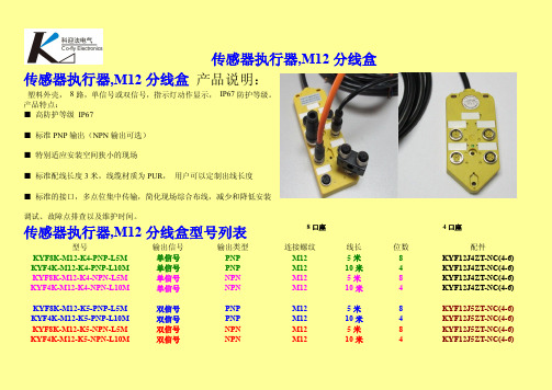
传感器执行器,M12分线盒传感器执行器,M12分线盒产品说明:塑料外壳,8路,单信号或双信号,指示灯动作显示,IP67防护等级。
产品特点:■高防护等级IP67■标准PNP输出(NPN输出可选)■特别适应安装空间狭小的现场■标准配线长度3米,线缆材质为PUR,用户可以定制出线长度■标准的接口,多点位集中传输,简化现场综合布线,减少和降低安装调试、故障点排查以及维护时间。
传感器执行器,M12分线盒型号列表8口座4口座型号输出信号输出类型连接螺纹线长位数配件KYF8K-M12-K4-PNP-L5M单信号PNP M125米8KYF12J4ZT-NC(4-6) KYF4K-M12-K4-PNP-L10M单信号PNP M1210米4KYF12J4ZT-NC(4-6) KYF8K-M12-K4-NPN-L5M单信号NPN M125米8KYF12J4ZT-NC(4-6) KYF4K-M12-K4-NPN-L10M单信号NPN M1210米4KYF12J4ZT-NC(4-6) KYF8K-M12-K5-PNP-L5M双信号PNP M125米8KYF12J5ZT-NC(4-6) KYF4K-M12-K5-PNP-L10M双信号PNP M1210米4KYF12J5ZT-NC(4-6) KYF8K-M12-K5-NPN-L5M双信号NPN M125米8KYF12J5ZT-NC(4-6) KYF4K-M12-K5-NPN-L10M双信号NPN M1210米4KYF12J5ZT-NC(4-6)传感器执行器,M12分线盒传感器执行器,M12分线盒技术参数传感器执行器,M12分线盒传感器执行器,M12分线盒单信号接线图传感器执行器,M12分线盒M12传感器执行器分线盒主要适用于下列目标市场:-工业自动化生产线(如汽车、钢铁、食品、包装、设备等各种工业产品自动化生产线)-电力电气、石油、天然气、工业气体、工业液体、核电、矿山等恶劣工作环境下的电源连接、布线及检测-工业控制(如气压控制,液压控制及其它流体控制)-机械设备制造、医疗设备制造传感器执行器,M12分线盒-军工产品制造-其它对IP防护级要求很高的工业及电子产品分线盒用在开关和面板之间具有下列优点:–节省了60%的安装时间–-减少了故障停机时间,电缆和开关都很容易更换–-降低了对维护人员工作技能的要求,LED指示可以帮助诊断故障信息M12传感器执行器分线盒对于设备制造商的优势体现在1:简化接线设计方案-减少接线时间-减少接线错误-减少设备制造时间-降低单台设备的成本2;减少材料–-较少的端子–-较少的DIN导轨–-较少的电缆密封管–-较小的电缆桥架–-较小和较少的穿线管3:其他优点–-制造更小的设备–-减少运输成本–-减少框架和柜体的材料–-减少人工M12传感器执行器分线盒最终用户的优势体减少停机时间–-更容易的计划维修传感器执行器,M12分线盒–-减少设备维护人员的数量–-更小的设备–-减少备件库存压力。
常用的传感器简单介绍及和PLC的接线传感器是一种检测装置,能感受到被测量的信息,传感器具有微型化、数字化、智能化、多功能化、系统化、网络化等特点。
它是实现自动检测和自动控制的主要环节。
按照传感器的基本感知功能,传感器分类可分为:热敏元件、光敏元件、气敏元件、力敏元件、磁敏元件、湿敏元件、声敏元件、放射线敏感元件、色敏元件和味敏元件等共计十大类。
按照输出类型传感器可以分为PNP和NPN式(也有叫源型传感器和漏型传感器)。
1.PNP(源型)传感器PNP型传感器的原理如上图所示,集电极和发射极为P结,基极为N结。
为了保证三极管能正常导通,集电极必须接负极,基级必须接负极,发射极必须接正极(发射结正偏,集电结反偏)。
集电结上会有一个负载,一般为下拉电阻,在负载的上端口是OUT信号输出线。
所以整个传感器需要接三根线。
集电极接负极发射极接正极OUT信号线接到PLC输入端口中。
当传感器导通时,集电极和发射极也会导通,此时OUT信号线与发射极,也就是电源的正极连在一起,所以对于PNP型传感器,当传感器导通时,信号输出的是高电平。
根据PLC 输入端口的接法,PLC输入模块的公共端必须接负极才能保证传感器正确运行。
PNP型和PLC接线:PNP型传感器,信号线与正极连载一起,信号线输出为高电平,此时要求PLC公共端接负极,才能保证形成回路。
PNP型传感器在PLC选型时,三菱的要选择支持源型的PLC或者同时支持源型漏型的PLC;西门子的PLC要选择支持漏型的PLC或者同时支持源型漏型的PLC。
2.NPN(漏型)传感器NPN型传感器的原理如上图所示,集电极和发射极为N结,基极为P结。
为了保证三极管能正常导通,集电极必须接正极,基级必须接正极,发射极必须接负极(发射结正偏,集电结反偏)。
集电结上有一个负载,一般为上拉电阻,在负载的下端口是OUT信号输出线。
所以整个传感器需要接三根线。
集电极接正极发射极接负极OUT信号线接到PLC输入端口中。
BNI IOL-309-002-Z019 IO-Link 1.1 sensor/actuator hubwith extension portUser's GuideBalluff Network Interface / IO-Link BNI IOL-309-002-Z019Contents1User Instructions 4 1.1.About This Manual 4 1.2.Structure of the Manual 4 1.3.Typographical Conventions 4Enumerations 4 Actions 4 Syntax 4 Cross-references 4 1.4.Symbols 4 1.5.Abbreviations 4 1.6.Differing views 4 2Safety 5 2.1.Intended use 5 2.2.Installation and Startup 5 2.3.General Safety Notes 5 2.4.Resistance to Aggressive Substances 5Dangerous voltage 5 3First Steps 6 3.1.Connection Overview 6 3.2.Mechanical Connection 7 3.3.Electrical Connection 7Functional ground 7 IO-Link connection 7 Connecting the sensor hub 8 Module variants 8 Sensor/actuator interface 8 Extension port 8 4General Configuration 9 4.1.Extension port 9Extension port configuration 55hex9 Setting the serial number 54hex9 5Configuration: "Extension Off" 10 5.1.IO-Link Data 10 5.2.Process Data Input 10 5.3.Process Data Ouput 10 5.4.Parameter Data/Demand Data 11Parameter Data/Demand Data 11 Inversion of the inputs 40hex12 Configuration In-Outputs 41hex12 Safe state of Outputs 42hex12 Voltage monitoring 44hex14 Monitoring the outputs 45hex14 6Configuration: extended with BNI IOL-102-002-Z019 15 6.1.IO-Link Data 15 6.2.Process Data/Input Data 15 6.3.Process Data/ Output Data 16 6.4.Parameter Data/Demand Data 17Parameter Data/Demand Data 17 Inversion of the inputs 40hex18 Configuration In-/Output 41hex18 Safe state of Outputs 42hex19 Safe state of the outputs on Pin 4 42hex19 Voltage monitoring 44hex20 Monitoring the outputs 45hex20 Setting the serial number 54hex207Diagnosis 21 7.1.Error Codes/ Errors 21 7.2.Events 21 8IO-Link Functions 22 8.1.IO-Link Version 1.0 / 1.1 22 8.2.Data Storage 22 8.3.Block Configuration 22 8.4.Resetting to Factory Settings 22 9Technical Data 23 9.1.Dimensions 23 9.2.Mechanical Data 23 9.3.Electrical Data 23 9.4.Operating conditions 23 10Function Indicators 24 10.1.Function Indicators 24LED-Indicators module status 24 Digital LED indicators for inputs/outputs 25 Extension port 25 11Appendix 26 11.1.Type Code 26 11.2.Ordering Information 26Balluff Network Interface / IO-Link BNI IOL-309-002-Z019 1User Instructions1.1.About ThisManual This manual describes the Balluff IO-Link I/O module, also called a sensor/actuator hub. The IO-Link protocol is used to link to the higher-level master module.In terms of function, this compact, cost-effective module is similar to a passive splitter box; it records digital and analog sensor signals and transmits them over the IO-Link interface. It passes control signals coming over IO-Link to the connected actuators.1.2.Structure of theManual The manual is organized so that the sections build on one another. Chapter 2: Basic Safety Information.……..1.3.TypographicalConventionsThe following typographical conventions are used in this manual.Enumerations Enumerations are shown as a list with an dash.−Entry 1.−Entry 2.Actions Action instructions are indicated by a preceding triangle. The result of an action is indicated by an arrow.➢Action instruction 1.Action result.➢Action instruction 2.Syntax Numbers:Decimal numbers are shown without additional indicators (e.g. 123).Hexadecimal numbers are shown with the additional indicator hex (e.g. 00hex).Cross-references Cross-references indicate where additional information on the topic can be found.1.4.Symbols Attention!This symbol indicates a safety instruction that must be followed without exceptionNoteThis symbol indicates general notes.1.5. Abbreviations BNIDPPI/O portEMCFEIOLLSBMSBSPDU Balluff Network Interface Direct Parameter Page Digital input/output port Electromagnetic compatibility Function EarthIO-LinkLeast Significant BitMost Significant BitService Protocol Data Unit1.6.Differing views Product views and images in this manual may differ from the product described. They areintended to serve only as illustrations.2Safety2.1.Intended use The BNI IOL-… acts as a decentralized input/output sensor module, which is connected to ahigher-level IO-Link master module through an IO-Link interface.2.2.Installation andStartup Attention!Installation and startup must only be carried out by trained technical personnel. Qualified personnel are people who are familiar with installation and operation of the product and have the necessary qualifications for these tasks. Any damage resulting from unauthorized tampering or improper use voids the manufacturer's guarantee and warranty. The operator must ensure that appropriate safety and accident prevention regulations are observed.2.3.General SafetyNotes Commissioning and inspectionBefore commissioning, carefully read the user's guide.The system must not be used in applications in which the safety of persons is dependent upon proper functioning of the device.Authorized personnelInstallation and startup must only be carried out by trained technical personnel.Intended useWarranty and liability claims against the manufacturer are rendered void by: −Unauthorized tampering−Improper use−Use, installation or handling contrary to the instructions provided in this user's guideObligations of the operating companyThe device is a piece of equipment in accordance with EMC Class A. This device can produce RF noise. The operator must take appropriate precautionary measures. The device may only be used with an approved power supply. Use only approved cables. MalfunctionsIn the event of defects and device malfunctions that cannot be rectified, the device must be taken out of operation and protected against unauthorized use.Intended use is ensured only when the housing is fully installed.2.4.Resistance toAggressiveSubstances Attention!The BNI modules always have good chemical and oil resistance. When used in aggressive media (such as chemicals, oils, lubricants and coolants, each in a high concentration (i.e. too little water content)), the material must first be checked for resistance in the particular application. No defect claims may be asserted in the event of a failure or damage to the BNI modules caused by such aggressive media.Dangerous voltage Attention!Before maintenance, disconnect the device from the power supply.NoteIn the interests of product improvement, Balluff GmbH reserves the right to change the technical data of the product and the content of this manualat any time without notice.Balluff Network Interface / IO-Link BNI IOL-309-002-Z0193 First Steps3.1. ConnectionOverviewFigure 3-1: Connection overview BNI IOL-309-002-Z0191 Ground connection2 Mounting hole3 Status LED: communication4 Label5 Port 16 Port 37 Port 58 Port 7, extension port9 Pin/Port LED: signal status 10 Port 6 11 Port 4 12 Port 2 13 Port 0 14 IO-Link interface12 345678 2910111213143 First Steps3.2.MechanicalConnectionThe BNI IOL modules are attached using 2 max. M4 screws and 2 washers.3.3.ElectricalConnection The BNI IOL-309-002-Z019 modules do not require a separate supply voltage connection. Supply voltage is provided via the IO-Link interface and the higher-level IO-Link master module.FunctionalgroundThe modules are equipped with a ground connection.Figure 3-3: BNI ground connection IOL-309...➢Connect the sensor hub module to the ground connection.NoteThe functional ground connection from the housing to the machine must havelow-impedance and be kept as short as possible.IO-LinkconnectionThe IO-Link connection is established via an M12 connector (A-coded, male).IO-Link (M12, A-coded, male)Pin Function1 Supply voltage for controller US, +24 V2 Supply voltage actuator UA, +24 V3 GND, reference potential4 C/Q, IO-Link data transmission channelBalluff Network Interface / IO-Link BNI IOL-309-002-Z019 3 First StepsConnecting the sensor hub ➢Connect ground conductor to the functional ground connection, if available.➢Connect the incoming IO-Link cable to the sensor hub.NoteA standardized sensor cable is used to connect to the higher-level IO-Link master module. Maximum length of 20 m.Module variants Sensor hub variants Digital portBNI IOL-309-002-Z019 IN / OUT Sensor/actuatorinterfaceStandardl input/output port M8Pin Function IN / OUT1 +24V4 In /Out3 0VNoteFor the digital inputs, the input guideline specified in EN 61131-2, Type 3 appliesNoteUnused input port sockets must be fitted with blind caps to ensure the IP67degree of protection.Extension port Extension port (M8, female)The port acts like a sensor/actuator interface if the extension function is disabled.Pin Function IN / OUT1 +24V4 Communication3 0VNoteA standardized sensor cable is used to connect to the device/sensor to be expanded. Maximum length of 20 m.4General Configuration4.1.Extension port The BNI IOL-309-002-Z019 module gives you the ability to use the No. 7 slot in variousways. By default, it is used as a digital I/O slot, where pin 4 can be used as a digital input oroutput.This slot can be used as an extension port by making a corresponding entry in theparameter with an index of 55hex. This makes it possible to operate one of the followingmodules using the No. 7 slot.•BNI IOL-102-002-Z019Extension port configuration 55hexConfiguration Index 0x55 valueBNI IOL-309-002-Z019 0BNI IOL-309-002-Z019 with BNI IOL-102-002-Z019 1NoteThe "Factory reset" command does not affect the configuration of the extensionport in any way.NoteThe process data length depends on the configuration.The extension port can be configured using parameter 0x55 (table). If data storage or validation is used, validation (identical) must be used for configuring. Depending on the system, the Device ID has to be entered (parameter data table) or the Device ID is read out from the IODD.Setting the serial number 54hex The serial number has a default value of 16x00hex.In order to use the "Identity" master validation mode, aserial number can be set using this parameter.This prevents a device from connecting to the wrong master port.Balluff Network Interface / IO-Link BNI IOL-309-002-Z019 5Configuration: "Extension Off"5.1.IO-Link Data5.2.Process DataInput5.3.Process DataOuput5 Configuration: "Extension Off"Data/DemandDataParameterData/DemandDataBalluff Network Interface / IO-Link BNI IOL-309-002-Z019 5 Configuration: "Extension Off"Inversion of theinputs 40hexInversion port (x):0 – Normal1 – Inverted.ConfigurationIn-Outputs 41hex0 – Input1 – OutputSafe state of Outputs 42hex The safe state parameter makes it possible to configure the outputs in case of a fault. If no IO-Link communication is possible or the "valid flag" of the output process data has not been set by the master, then each output adopts the configured status. The following statuses can be configured for each pin.5 Configuration: "Extension Off"Balluff Network Interface / IO-Link BNI IOL-309-002-Z019 5 Configuration: "Extension Off"monitoring44hexMonitoringthe outputs45hex6Configuration: extended with BNI IOL-102-002-Z0196.1.IO-Link DataData/InputDataBalluff Network Interface / IO-Link BNI IOL-309-002-Z019 6 Configuration: extended with BNI IOL-102-002-Z0196.3.Process Data/Output Data6 Configuration: extended with BNI IOL-102-002-Z019Data/DemandDataParameterData/DemandDataBalluff Network Interface / IO-Link BNI IOL-309-002-Z0196Configuration: extended with BNI IOL-102-002-Z019Inversion of the inputs 40hex0 - Normal 1 - InvertedConfiguration In-/Output 41hex6 Configuration: extended with BNI IOL-102-002-Z019Safe state of Outputs 42hex The safe state parameter makes it possible to configure the outputs in case of a fault. If no IO-Link communication is possible or the "valid flag" of the output process data has not been set by the master, then each output adopts the configured status. The following statuses can be configured for each pin.Safe state of the outputs on Pin 4 42hexBalluff Network Interface / IO-Link BNI IOL-309-002-Z019 6 Configuration: extended with BNI IOL-102-002-Z019Voltagemonitoring44hexMonitoring theoutputs 45hexSetting the serial number 54hex The serial number has a default value of 16x00hex.In order to use the "Identity" master validation mode, a serial number can be set using this parameter.This prevents a device from connecting to the wrong master port.7Diagnosis7.1.Error Codes/Errors7.2.EventsBalluff Network Interface / IO-Link BNI IOL-309-002-Z019 8IO-Link Functions8.1.IO-LinkVersion 1.0 /1.1 This device can be operated with an IO-Link master according to IO-Link version 1.0 and version 1.1. Version-specific functions such as data storage (version 1.1) areonly supported in combination with a suitable IO-Link master.8.2.Data Storage Each IO-Link master of IO-Link version 1.1 features data storage in which an image of the IO-Link device configuration can be stored. When a device is replaced, the stored configuration isautomatically transferred to the new device. This guarantees minimal downtime. Validationmust be switched on in order to use the data storage. For information about the configuration ofdata storage and validation, please refer to the user's guide of the respective IO-Link master.8.3.BlockConfiguration The device supports block configuration. This allows all parameters in adata block to be consistently imported from a controller or a configuration tool into the device.8.4.Resetting toFactorySettings The factory settings on the device can be restored by running the "restore factory settings" system command.0x82 must be written to Index 2 Subindex 0 for the command. The extension port setting is not reset in this process.9Technical Data9.1.Dimensions9.2.Mechanical Data9.3.Electrical Data9.4.OperatingconditionsBalluff Network Interface / IO-Link BNI IOL-309-002-Z019 10Function Indicators10.1.FunctionIndicatorsLED-Indicators module statusCOM/ US/UA10 Function IndicatorsDigital LED indicators forinputs/outputsLED 0, input/output on Pin 4ExtensionportThe table is valid if the extension port is active. If the extension port is used as a standard I/O, then the description from "Digital LED indicators for inputs/outputs" can be used.Balluff Network Interface / IO-Link BNI IOL-309-002-Z019 11Appendix11.1.Type Code11.2.OrderingInformationBNI IOL-309-002-Z019 Balluff Network InterfaceIO-Link interfaceFunctions309= 8 inputs/outputsVariants002 = with IO-Link 1.1 extension portMechanical configurationZ019 = Die-cast zinc housing, matte nickel platedBus connection and power supply:1x M12x1 external thread,I/O ports: 8 x M8x1, internal threadNotesBalluff GmbH Schurwaldstrasse 9 73765 Neuhausen a.d.F. Germany N o . 9 2 6 0 2 9 -7 2 6 E •0 1 . 1 3 0 6 1 5•E d i t i o n A 2 1•R e p l a c e s E d i t i o n I 1 8•S u b j e c t t o m o d i f i c a t i o n。
数字传感器以及由数字信号驱动的激励器的应用非常广泛,几乎所有现实中的变量(如温度、流量、压力、速度等等)测量中都可以找到数字传感器的应用,其数字输出有多种格式,本文首先根据输出信号和电路接口的类型对数字传感器分类,然后指出在选择与传感器接口的数字I/O模块时应注
意哪些问题。
数字传感器与模拟传感器不同,模拟传感器的输出值是一个在整个输出范围内连续变化的值,而数字传感器的输出值只有两种,非“0”即“1”。
轻触开关(touch switch)就是数字传感器的一个最简单的例子,在未被按下时,轻触开关通常是一个阻抗无穷大的开路电路,而按下之后,就变成一个阻抗为零的短路电路。
在将数字传感器与数据捕获设备对接时,必须考虑一些可能影响接口性能的关键因素。
下文中,我们将介绍这些关键因素,并为你提供一种简易方法,以指导你正确选择适合你应用的数据捕获设备。
数字传感器的分类
由于技术进步,市场上出现了各种各样复杂的数字传感器,而且如今的传感器已经能够产生一长串的开关状态转换,使用这些传感器时,输出脉冲序列的频率特性,甚至是脉冲形状都能表征传感器的测量结果,从而使得连续测量变为可能。
图1按照传感器输出的驱动信号的信号特征对传感器进行分类(有5种),其中,45%的数字传感器是以数字线的开关状态表征输出,35%以输出信号的频率表征输出,12%则是以输出信号的占空比来表征输出,另有6%以时间间隔表征,2%以脉冲数表征。
在选择捕获传感器数据所需的工业数字模块时,能够表达传感器测量结果的信号特征是第一个需要考虑的选择参数。
在决定你所选择的数字I/O模块中是否需要计数器时,这一参数十分重要。
吸入和泵出这两个术语定义了负载中直流电流的流向控制。
吸入型器件为电流提供一条到地的通路,不负责为设备供电。
凡名字中包含NPN、集电极开路和IEC负逻辑这些术语的器件都属于吸入型器件。
泵出型器件提供电源或一个正电压,将电流灌入负载。
凡名字中包含PNP、发射极开路、常低和IEC正逻辑等术语的器件都属于泵出型器件。
吸入和泵出的概念与用来完成操作的元件无关(不论元件是晶体管、机械继电器还是其它)。
这一概念对任何DC电路均适用,但用于实现这一电路的元件可以有多种选择。
2线传感器或3线传感器
对于定义传感器开态和关态时电流和电压的关系而言,十分重要。
一个传感器可按以下方式被归为2线传感器或3线传感器。
2线传感器
这种传感器与数据捕获设备串联,当传感器未被激活时,它只吸收一个最小操作电流,这一电流值等于传感器的关态泄漏电流,有些传感器厂商也称之为残余电流。
当传感器没有连接数据捕获设备,
而直接连接到其它负载上时,就不存在残余电流问题,例如在工业环境中,这些2线传感器就常常直接连接到电机,以及类似电机的低阻设备。
但如果传感器所需的残余电流高于数字I/O模块能够提供的电流,那么问题就出现了。
这时数字I/O模块可能会因为传感器吸收的电流高于它准备提供的电流而错误地将关态检测为开态。
工业应用中的大多数2线传感器的关态泄漏电流或残余电流都不高于1.7毫安。
与关态类似,传感器要维持开态也需要一个最小电流,这就是最小保持电流(minimum holding current),其值通常在3毫安到20毫安之间。
如果数字I/O模块不能吸收或提供该电流,那么传感器将无法正常工作。
3线传感器并不直接通过数字输出线获取能量,而是从一个激励终端获取能量,某些厂商也将这种传感器叫做线路驱动传感器。
这类传感器从数字I/O模块处吸收的电流叫做负荷电流,通常为20毫安左右。
但注意,该电流是由激励终端提供的。
数字传感器驱动电路
按照实现传感器输出的电子元件分类。
用于驱动数字传感器输出的电子元件通常有三种:机械继电器、晶体管和双向FET器件。
机械继电器是一种电磁器件,闭合触点时能够接通电路,断开触点时能够切断电路。
这种器件能够承受高压下的电流负载。
机械继电器相对于固态继电器而言属于低速器件,因此通常用于以线路状态表征输出结果的传感器中。
这种器件常出现的问题是触点老化和阻抗增大,其触点的寿命取决于电流负荷和工作频率。
在与计数器或者数字I/O模块连接时,机械继电器有时会由于触点反弹而输出不确定的结果。
晶体管是一种用于控制DC电流的固态器件,有两种类型:NPN型和PNP型,通常在低直流电源的传感器中用作输出开关。
图2给出了一个NPN(电流吸收)型集电极开路晶体管。
双向FET器件是以一种叫做双向FET输出的结构实现的,如图3所示。
该结构有许多优点,但最重要的是它能够直接与TTL和CMOS电路接口,而且它具有关态泄漏电流低和响应速度快的特性。
FET的意思是场效应晶体管,它是一种最适合于用作数字传感器输出的器件,因为其工作特性接近理想模型。
数字传感器I/O模块的选择
在选择数字I/O模块时,我们必须回答以下三个问题:
1.传感器输出的数字信号的什么特征能够表征传感器的测量结果?从列表1你就能选择一组数字I/O模块。
2.传感器的输出是吸入型输出还是泵出型输出?表1同样也提供了一组根据吸入和泵出能力分类的NI数字I/O板,如果你所采用的传感器是吸入型输出,那么你就需要选择一块泵出型输入的I/O板,反之亦然。
3.用来实现传感器输出的是什么元件?这时我们可能就需要考虑传感器的关态泄漏电流和开态最小保持电流。
比较表2中传感器的规格和数据捕获设备的规格,你就能选出最适合你传感器的数字I/O设备。
在选择过程中,除了考虑电压之外,以下两个条件也必须受到重视(有时我们会将其忽略):
1.传感器的关态泄漏电流≤I/O板的低态最大输入电流;
2.传感器的最小保持电流≤I/O板的高态最大输入电流。