亿光红外线接收头IRM-8755K-2
- 格式:pdf
- 大小:215.38 KB
- 文档页数:7

国内最全LED生产、供应商名录深圳市富佳鑫光电有限公司[省份:广东省][2008-10-15]富佳鑫光电有限公司创建于1998年,是一家专业从事LED电子产品的开发、加工、生产、销售和服务于一体化的民营企业。
本公司技术力量雄厚。
规模经营,占地面积5000m2,目前员工150余人,投资额500万人民币,采用先进的成熟的全套生产设备及检验仪器,同时不断地引进先进的技术及管理经...深圳市华纳照明有限公司[省份:广东省][2010-05-25]深圳市华纳照明有限公司创建于2006年,是一家专业从事LED电子产品的开发、加工、生产、销售和服务于一体化的民营企业。
本公司技术力量雄厚。
规模经营,占地面积5000m2,目前员工150余人,投资额500万人民币,采用先进的成熟的全套生产设备及检验仪器,同时不断地引进先进的技术及管...上海升美电子有限公司[省份:上海市][2010-04-11]上海升美电子有限公司是一家专业致力于LED及其应用新产品开发、设计和生产销售的照明企业。
公司本着以―专注经营,缔造精品;用心呵护,至诚服务‖的经营理念,以国际先进科技讯息为动力,以城市亮化为主题,以优质的原材料及严格的生产流程不断开发高效节能,绿色环保,外观精美的...深圳万鑫光电子科技有限公司[省份:广东省][2010-03-24]深圳万鑫光电子科技有限公司,成立于2003年,历经多年的跨越式发展,现已成为一家拥有自主研发能力,集创新、生产和销售于一体的综合性LED制造大型企业,公司连续多年居国内领先地位。
万鑫光电是全球领先的LED研发制造商,总部位于经济特区----深圳。
―万鑫光电子‖为公...深圳市三一飞达科技有限公司[省份:广东省][2010-06-30]我司是一家集研发,生产,销售为一体的太阳能光伏的高科技企业。
公司实力雄厚,设备先进,技术精湛。
产品先进,节能,环保,质优,价廉,外型美观,精致。
广泛适用于公路,铁路,航海,航空,家庭,学校,企业,工厂,公司,公园和各种娱乐场所。

亿光红外线接收头电路工作原理文章出处:广州市超毅电子有限公司亿光红外线接收头主要应用在机顶盒,红外遥控系统上,亿光代理商超毅电子讲解一下关于接收头的工作原理,从电路,PD晶片以及放大电路中分析亿光红外线接收头的工作原理。
首先大家来看一下亿光红外线接收头的系统框架:从PD(光电二极管及其偏置电路上分析亿光红外线接收头的工作原理:PD晶片感应信号红外光,将接收到的光信号转换成电流信号。
红外线接收头的偏置电路向提供PD提供合理的方向偏置条件;对信号起可变阻抗的功效,消除干扰信号;将有大部分用信号传送到后级放大器。
TA(阻抗变换放大电路在PD和后级放大器之间起阻抗转换作用,将电流信号变换成电压信号;分离感应电流的交流和直流分量。
红外线接收头CGA(可控增益放大电路提供整个模块的主要增益(50-80dB;可以接受指令改变增益;受控于AGC(自动增益控制。
BF(带通滤波器根据信号的频域特征来消除干扰的手段,能消除来自于各种干扰源的干扰信号;通频带宽度为4KHz;优值为7-10以上;中心频率在IC出厂时调好,有多种中心频率供选用。
AGC(自动增益控制电路根据信号的时域特征来消除干扰的手段,能消除各种不同时间特征参数的干扰信号;基于脉冲簇时长和脉冲簇之间的间隙时间等参数,判别有用信号或干扰信号;不同型号的IC,对时间参数的判别依据不同;遇到干扰时,将CGA的增益调到最小,不让干扰信号通过;不会影响有用信号的接收;在黑暗的环境下,AGC将CGA的增益控制到很大的数值,但要保证没有自发的输出。
以上就是亿光红外线接收头的工作原理,根据各电路分析的红外线接收头接收头,亿光代理商超毅电子主推红外线接收头IRM3638系列,如果对于红外线接收头的技术咨询,可直接咨询客服,我们会为您提供技术支持以及应用资料。
免费咨询热线4008-800-932.。

智能小车红外循迹巡线传感器原理与应用电路2011-09-27 11:24智能小车是指由单片机控制的,可以修改程序的,在程序的控制下,能够自由移动,自动完成特定功能的小车。
它集计算机技术,软件编程,自动控制,传感器技术,机械结构于一体,是学习信息技术,机器人的最佳载体。
小车循迹指的是小车在白色地板上循黑线行走,通常采取的方法是红外探测法。
也可用CCD,CMOS 摄像头方案,光电优点:1.电路设计相对简单2.检测信息速度快3.成本低缺点:1.道路参数检测精度低、种类少2.检测距离短3.耗电量大4、容易受外界光线干扰摄像头优点:1.检测前瞻距离远2.检测范围宽3.检测道路参数多缺点:1.电路相对设计复杂2.检测信息更新速度慢3.软件处理数据较多红外探测法,即利用红外线在不同颜色的物体表面具有不同的反射强度的特点,在小车行驶过程中不断地向地面发射红外光,当红外光遇到白色纸质地板时发生漫反射,反射光被装在小车上的接收管接收;如果遇到黑线则红外光被吸收,小车上的接收管接收不到红外光。
单片机就是否收到反射回来的红外光为依据来确定黑线的位置和小车的行走路线。
常用的红外探测元件有红外发光管,红外接收管,红外接收头,一体化红外发射接收管。
红外线是不可见光线。
所有高于绝对零度(-273.15℃)的物质都可以产生红外线。
人的眼睛能看到的可见光按波长从长到短排列,依次为红、橙、黄、绿、青、蓝、紫。
其中红光的波长范围为0.62~0.76μm;紫光的波长范围为0.38~0.46μm。
比紫光波长还短的光叫紫外线,比红光波长还长的光叫红外线。
红外发光二极管:外形和普通发光二极管LED相似,发出红外光。
管压降约1.4v,工作电流一般小于20mA。
为了适应不同的工作电压,回路中常常串有限流电阻。
红外线发射管有三个常用的波段,850NM、875NM、940NM。
根据波长的特性运用的产品也有很大的差异,850NM波长的主要用于红外线监控设备,875NM主要用于医疗设备,940NM波段的主要用于红外线控制设备。


谨至执事者:兹提供贵公避开产品之有关详细规格及影像资料,敬请给予办理测试承认手续,同时敬请送返一份附有贵公司承认之测试承认后样品承认书.We are please in sending you herewith our specification and drawings for your approval.Please return to us one copy "For Approval"with your approved signatures.品名Commodity:红外发射管型号Model NO.发出日期Issue Date:2021/11/01承认日期Approval Date.客戶Customer:经办者Diretor:职称Title:联络手机Mobile:联络电话Tel:联络传真Fax:E-Maile:承认签章Approval Signatures客户确认:Commerce 审核:Checked by :编制:Prepared by:日期:Date:日期:Date:日期:Date:樣品承認書Approval SheetYGX-IR26-71C-L447-TR8TOP 发光二极管TOP Light Emitting Diode技术数据表Technical DataSheet本产品主要应用于各类使用表面贴装结构的电子产品中,如红外遥控的通讯,LED 智能家居的组成单元等。
本产品也广泛用于各类室内外的检测设备。
This product is generally used for electronic equipment such asdashboard and signal LED board.And it also be widely used for indoor and outdoor decorative lighting.特性:封装材料:环氧树脂Features:Encapsulation:Resin 焊接方法:无铅焊接Soldering methods:Pb-Free soldering 功率高,功耗低,可靠性好,寿命长High Luminous Intensity ,Low Power Dissipation,good Reliability and Long Life.符合欧盟公布的ROHS 指令要求Complied With ROHS Directive目录Catalogue 1光电参数Electro-Optical Characteristics 2典型特性曲线Typical Characteristic Curves 3可靠性实验Reliability Test Items And Conditions 4外形尺寸Outline Dimensions 5包装Packaging 6焊接指导Guideline for Soldering 8使用注意事项Precautions 9产品规格如因工艺改进而有所改变,恕不另行通知。
红外线遥控接收头在3D眼镜上的应用
超毅电子蒋文霞
随着3D电视的普及,3D眼镜也越来越多,目前主流的“主动式快门3D眼镜”使用了最新的红外线遥控接收头,用它来接收电视发过来的同步信号。
这种主动式快门眼镜技术的优点在于它的残影少,而且不论是电视、电脑屏幕还是投影机,只要更新频率能达到要求,就能导入这个技术,因此现在市面上大部份即将上市的3D显示系统,包括Sony、Panasonic、Samsung等电视上,及NVIDIA的3D眼镜和部份的电影院,都可以看到主动式快门眼镜的踪迹。
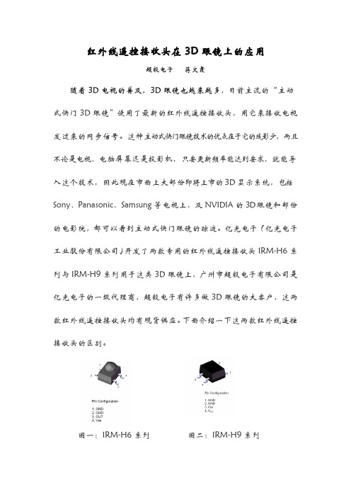
亿光电子(亿光电子工业股份有限公司)开发了两款专用的红外线遥控接收头IRM-H6系列与IRM-H9系列用于这类3D眼镜上,广州市超毅电子有限公司是亿光电子的一级代理商,超毅电子有许多做3D眼镜的大客户,这两款红外线遥控接收头均有现货供应。
下面介绍一下这两款红外线遥控接收头的区别。
图一:IRM-H6系列图二:IRM-H9系列
这两款产品一个有聚光透镜,一个是平面接收的,仅仅是接收角度不同,其它地方都是一样的。
图三:IRM-H6系列
图四:IRM-H9系列
这两款产品均支持3V电压工作,且工作电流小,非常适合电池供。
图五:工作参数
图六:工作原理图
工作频率有宽频(20-60KHz通用)与定频(20KHz)两种方式,
图七:宽频频谱图
图八:定频频谱图
信号脉宽有两种,一种是200uS,一种是600us可适应多种编码方式。
图九:150us脉宽
图十:600us脉宽。
红外线发射接收管IR/PT/PD产品介绍——超毅电子今天超毅小编为大家分享红外线发射接收管IR/PT/PD产品的详细资料,希望能帮到大家进一步开发应用。
红外线发射接收管IR/PT/PD,以产品波长范围分类,可分为:可见光400~700nm、紫外線,X-ray400nm以下、紅外線,無線電波700nm以上三大类。
其中,紫外线和红外线属不可见光,目前,不可见光的波长范围有:红外线发射管(940nm---IR、850nm---HIR、875nm---SIR),红外线接收管PT/PD(400~1100nm、700~1100nm、760~1100nm、840~1100nm)红外线发射接收管IR/PT/PD,以产品外形分类,可分为:直插Lamp型、贴片SMD 型、Side LookIR (Infrared Emitter Diode)红外线发射管原理介绍1.发光二极管2.将电能转换成光能3.工作方式:输入—顺向电流产品特性:1.High reliability 高性能2.Low voltage 低电压3.High radiant power 高辐射功率PT (Photo Transistor)光敏二极管或红外线接收管原理介紹1.光电晶体(NPN电晶体)2.将光能转换成电能3.工作方式供给一工作电压(VCE)PT产品的主要特性:1.High reliability 高性能2.Low cost 低成本3.Match visible light and nearInfrared range usage. 匹配可见光及近红外光产品使用4.No Base connection 无需基极连接5.High spectral sensitivity高光谱灵敏度PD (Photodiode)光敏三极管或红外线接收管原理介绍1.光二极体(PN二极体)2.将光能转换成电能3. 工作方式供给—逆向电压(Vr)PD产品的主要特性:1.High reliability 高性能2.High spectral sensitivity高光谱灵敏度3.Matches visible light and near Infrared range usage可匹配可见光及近红外光产品使用4.Low noise 低杂讯IR/PT/PD产品的应用电视遥控器上、安全光栅、空调遥控器、玩具遥控、CCD相机、一般的光学传感器、红外线触摸屏、烟雾感应器、3D眼镜、小家电、扫描仪、游戏机、投币机、安防产品、科教产品、感应洁具、光学微型投影机、验钞机、油质检测仪、车载DVD、工业电脑、音响、医疗设备等周边产品IR/PT/PD常用料号:IR908-7C-F、IR928-6C-F、IR333C-6-A、PD333-3C、HIR333C-A、IR333C-A、IR204-H60、PT204-6B、IR204-A,PT204-6B、IR928-6C、PT91-21B、PD95-21B-TR10等广州市超毅电子有限公司。
红外线遥控接收头工作原理
红外线遥控接收头的工作原理:当红外发射管发射出一组红外线后,如果接收器接收到了红外信号,接收头将其放大、整形后,通过天线送至接收器。
红外线遥控接收头主要由控制电路、前置放大电路和红外接收头三部分组成。
1.控制电路
该部分包括四部分:输入端(输入信号)、输出端(输出信号)、整形放大电路和红外发射管。
输入端(输入信号)用来控
制接收头的工作状态,输出端(输出信号)用来驱动红外发射管,整形放大电路使接收头的输出信号与输入信号达到同步,红外发射管产生红外线并传输到接收头,而红外接收管将发射出来的红外线转换成电信号,再经放大、整形后送到解调器,解调后的信号经过解调电路解调出模拟量。
2.前置放大电路
该部分包括四部分:放大电路、滤波电路和共模抑制电路。
前置放大电路的作用是将接收头发出的红外线通过后级放大、整形后变成可供本系统使用的红外线。
另外,在一些设计中还需要根据实际需要适当地调节前置放大电路的增益。
—— 1 —1 —。
Technical Data SheetInfrared Remote-control Receiver ModuleIRM-H6XXT/TR2 Features‧High shielding against electric field disturbance.‧Circular lens to improve the receive characteristic.‧Line-up for various center carrier frequencies.‧Low voltage and low power consumption.‧High immunity against ambient light.‧Photodiode with integrated circuit.‧TTL and CMOS compatibility.‧Top-received SMD.‧Suitable burst length ≧10 pulses/burst.‧This product itself will remain within RoHS compliant version.‧Pb free.‧External dimensions 5(L)*7(W)*4(H)mm.DescriptionsThe device is a miniature SMD type infrared remotecontrol system receiver that has been developed anddesigned by utilizing the most updated IC technology. ThePIN diode and preamplifier are assembled on lead frame,the epoxy package is designed as an IR filter. Thedemodulated output signal can directly be decoded by amicroprocessor.Applications1. Light detecting portion of remote control․AV instruments such as Audio, TV, VCR, CD, MD, etc.․Home appliances such as Air-conditioner, Fan , etc.․The other equipments with wireless remote control.․CATV set top boxes․Multi-media EquipmentDevice Selection GuidePART MATERIAL COLORChip Silicon ---Package Epoxy BlackIRM-H6XXT/TR2 Absolute Maximum Ratings (Ta=25℃)Parameter Symbol Rating Unit NoticeSupply Voltage Vcc 0~6 V Operating Temperature Topr -25 ~ +85 ℃Storage Temperature Tstg -40 ~ +85 ℃Recommended Operating ConditionSupply Voltage Rating: Vcc 2.7V to 5.5VElectro-Optical Characteristics (Ta=25℃, and Vcc=3.0V)Parameter SymbolMIN.TYP.MAX.UnitCondition Supply Current Icc --- --- 1.2 mA No signal input Peak Wavelength λp--- 940 --- nmL08 --- ---Reception DistanceL45 5 --- ---mHalf Angle(Horizontal) Θh--- 45 --- deg At the ray axis*1Half Angle(Vertical) Θv--- 45 --- degHigh Level Pulse Width T H400 --- 800 μs Low Level Pulse Width T L400 --- 800 μs At the ray axis*2High Level Output Voltage V H 2.7 --- --- V Low Level Output Voltage V L--- 0.2 0.5 V Notes:*1:The ray receiving surface at a vertex and relation to the ray axis in the range of θ= 0° and θ=45°.*2:A range from 30cm to the arrival distance. Average value of 50 pulses.IRM-H6XXT/TR2 The Notice of Application:Transmission remote control signal consist of four parts: Encode Part, IR Transmitter Source, IRM device, Decode Part1. When IRM-H6XXT code select frequency, it need to well understand the center system ofencode part.2. Strong or weak light of IR Transmitter can affect distance of transmission.3. Minimum Burst Length T burst (number of pulses per burst) : 10 cycles4. It needs to ensure the translation range of decode part if it is applied to the pulse-width range. If the above items hardly assure of its application, it’ll cause NG(no good) message from the edge of signal.Note: This model might not work well with RCA code.Test Method:The specified electro-optical characteristics is satisfied under the followingConditions at the controllable distance.c Measurement placeA place that is nothing of extreme light reflected in the room.d External lightProject the light of ordinary white fluorescent lamps which are not highFrequency lamps and must be less then 10 Lux at the module surface.(Ee≦10Lux)e Standard transmitterIRM-H6XXT/TR2Application Circuit:RC Filter should be connected closely between Vcc pin and GND pin.IRM-H6XXT/TR2Fig.-8 Fig.-9 Relative Transmission Distance vs.Fig.-9 Arrival Distance vs. Ambient TemperatureCenter Carrier FrequencyReliability Test Item And ConditionThe reliability of products shall be satisfied with items listed below.Confidence level:90%LTPD:10%Reflow Terms: JEDEC Level 4 SpecificationDrying; Temp.:125℃ 24hrs Æ Moisture 30℃/ 60% RH 96hrs Æ Reflow Temp.: 260℃±5℃10sec, 3 timesNote:1. Not sooner than 15 minutes and not longer than 4 hours after removal from thetemperature/humidity chamber.2. The time between reflow shall be 5 minutes minimum and 60 minutes maximum.Recommended method of storageDry box storage is recommended as soon as the aluminum bag has been opened prevent moisture absorption. The following conditions should be observed, if dry boxes are not available:z Storage temperature 10℃ to 30℃z Storage humidity ≦60%RH max.After more than 72 hours under these conditions moisture content will be too high for Reflow soldering:In case of moisture absorption, the devices will recover to former condition by drying under the following condition:192 hours at 40℃+5℃/-0℃and 5%RH (dry air / nitrogen) or96 hours at 60℃+5℃and < 5%RH for all device containers or24 hours at 125℃+5℃not suitable for reel or tubes.ESD PrecautionProper storage and handing procedures should be followed to prevent ESD damage tothe devices especially when they are removed from the Anti-static bag. Electro-Static Sensitive Devices warning labels are on the packing.Recommended Solder Profile(1) Reflow soldering should not be done more than two times.(2) When soldering, do not put stress on the IRM-H6XXT/TR2 Series devices during heating.(3) After soldering, do not warp the circuit board.Soldering IronEach terminal is to go to the tip of soldering iron temperature less than 350℃ for 3 seconds within once in less than the soldering iron capacity 25W. Leave two seconds and more intervals, and do soldering of each terminal. Be careful because the damage of the product is often started at the time of the hand solder.RepairingRepair should not be done after the Devices have been soldered. When repairing is unavoidable, a double-head soldering iron should be used (as below figure). It should be confirmedBar Code Label亿光一级代理商超毅电子EVERLIGHT ELECTRONICS CO.,LTD.IRM-H6XXT/TR2Label Form SpecificationCPN: Customer’s Production Number P/N : Production Number QTY: Packing Quantity CAT: None HUE: None REF: Reference LOT No: Lot Number MADE IN CHINA: Production PlacePbRoHSIRM-H6XXT/TR2Notes1. Above specification may be changed without notice. EVERLIGHT will reserve authority on material change for above specification. 2. When using this product, please observe the absolute maximum ratings and the instructions for using outlined in these specification sheets. EVERLIGHT assumes no responsibility for any damage resulting from use of the product which does not comply with the absolute maximum ratings and the instructions included in these specification sheets. 3. These specification sheets include materials protected under copyright of EVERLIGHT corporation. Please don’t reproduce or cause anyone to reproduce them without EVERLIGHT’s consent.EVERLIGHT ELECTRONICS CO., LTD. Office: No 25, Lane 76, Sec 3, Chung Yang Rd, Tucheng, Taipei 236, Taiwan, R.O.CTel: 886-2-2267-2000, 2267-9936 Fax: 886-2267-6244, 2267-6189, 2267-6306 http:\\Everlight Electronics Co., Ltd. Device No:DMO-0000008http:\\ Prepared date:09 -26-2007Rev1Page: 11 of9Prepared by:IBU_NPID2。
Infrared Remote ControlReceiver ModuleIRM-8755K-2Features‧ High protection ability against EMI.‧ Circular lens to improve the receive characteristic. ‧ Line-up for various center carrier frequencies. ‧ Low voltage and low power consumption. ‧ High immunity against ambient light. ‧ Photodiode with integrated circuit. ‧ TTL and CMOS compatibility. ‧ Long reception distance. ‧ High sensitivity. 1 32 ‧ Pb freeDescriptionTheIRM-8755K-2 device are miniature type infrared remote control system receiver which has been developed and designed by utilizing the most updated IC technology.Pin Configuration1. OUT2. GND3. V SThe PIN diode and preamplifier are assembled on lead frame, the epoxy package is designed as an IR filter.The demodulated output signal can directly be decoded by a microprocessor.Applications• Light detecting portion of remote control• AV instruments such as Audio, TV, VCR, CD, MD, etc. • Home appliances such as Air-conditioner, Fan, etc. • The other equipments with wireless remote control. • CATV set top boxes • Multi-media EquipmentBlock DiagramApplication CircuitRC Filter should be connected closely between Vcc pin and GND pin.Infrared Remote ControlReceiver ModuleIRM-8755K-2Parts TablePackage Dimenstions(Dimensions in mm)Notes:Tolerances unless dimensions ±0.3mm.Infrared Remote ControlReceiver ModuleIRM-8755K-2 Absolute Maximum Ratings (T a=25°C)Parameter Symbol Rating UnitSupply Voltage Vcc 6 VOperating Temperature Topr -25 ~ +85 ℃Storage Temperature Tstg -40 ~ +85 ℃Soldering Temperature *1Tsol 260 ℃*1 4mm from mold body less than 10 secondsElectro-Optical Characteristics (Ta=25℃ and Vcc=5.0V)Parameter SymbolMIN.TYP.MAX.UnitCondition Consumption Current Icc --- --- 2 mA No signal input B.P.F Center Frequency Fo --- 36 --- KHz Peak Wavelength λp--- 940 --- nmL08 --- ---Reception DistanceL45 4 --- ---mHalf Angle(Horizontal) Θh--- 45 --- deg At the ray axis*2.Half Angle(Vertical) Θv--- 45 --- degHigh Level Pulse Width T H400 --- 800 μs Low Level Pulse Width T L400 --- 800 μs At the ray axis*3High Level Output Voltage V H 4.5 --- --- V Low Level Output Voltage V L --- 0.2 0.5 V*2. The ray receiving surface at a vertex and relation to the ray axis in the range of θ=0° and θ=45°. *3. A range from 30cm to the arrival distance. Average value of 50 pulses.Infrared Remote ControlReceiver ModuleIRM-8755K-2Test MethodThe specified electro-optical characteristics is satisfied under the following Conditions at the controllable distance.1. Measurement placeA place that is nothing of extreme light reflected in the room. 2. External lightProject the light of ordinary white fluorescent lamps which are not high Frequency lamps and must be less then 10 Lux at the module surface. (Ee 10Lu ≦x)3. Standard transmitterA transmitter whose output is so adjusted as to Vo=400mVp-pand the output Wave form shown inFig.-1.According to the measurement method shown in Fig.-2 the standard transmitter is specified. However, the infrared photodiode to be used for the transmitter should be λp=940nm,Δλ=50nm. Also, photodiode is used of PD438B (Vr=5V). (Standard light / Light source temperature 2856°K). 4. Measuring system According to the measuring system shown in Fig.-3Fig.-1 Transmitter Wave Form D.U.T output PulseFig.-2 Measuring Method Fig.-3 Measuring SystemInfrared Remote ControlIRM-8755K-2Receiver ModuleInfrared RemotePacking Quantity1000 pcs / Box10 Boxes / CartonInfrared Remote ControlIRM-8755K-2 Receiver ModuleDISCLAIMER1. Above specification may be changed without notice. EVERLIGHT will reserve authority on material changefor above specification.2. When using this product, please observe the absolute maximum ratings and the instructions for useoutlined in these specification sheets. EVERLIGHT assumes no responsibility for any damage resulting from use of the product which does not comply with the absolute maximum ratings and the instructions included in these specification sheets.3. These specification sheets include materials protected under copyright of EVERLIGHT. Reproduction inany form is prohibited without the specific consent of EVERLIGHT.。