TOFD超声波衍射时差法教程文稿演示
- 格式:ppt
- 大小:10.83 MB
- 文档页数:90
![TOFD(衍射时差法)的原理及应用[1]](https://uimg.taocdn.com/b53dae3e0912a2161479295c.webp)
一TOFD原理超声TOFD(Time of Flight Diffraction Technique –衍射时差法)技术就是用两个探头相向对置,一发一收,利用缺陷端部产生的散射波和衍射波,来检测出缺陷和评定缺陷的方法。
下图即表示TOFD法的探伤原理、探伤波形的模式图。
(a)TOFD原理图(b)波形图图(a)中,①为发射探头发射横向纵波沿试件表面传播的正向侧向波(Lateral wave),它是区分和测量缺陷的参考。
④为底面负向反射波(Back-wall reflection),当有裂纹缺陷存在时,在①④间会接收到缺陷上端的负向衍射波②(Upper Crack Tip Signal)和缺陷下端的正向衍射波③(Lower Crack TipSignal )。
这里只考虑纵波声速V ,忽略缺陷处的波形变换产生的横波等。
说明:TOFD 技术采用一发一收的方式,通常使用高阻压、窄脉冲压力探头,主压力波的反射角范围是45º至70º。
假定两探头间的距离为S ,试件的厚度为H ,裂纹在试件厚度方向的高度为L ,裂纹上端距离试件表面的埋藏深度为D ,沿试件表面传播的侧向波的接收时间为t L , 接收到缺陷上端的负向衍射波的时间为t 1,接收到缺陷下端的正向衍射波的时间为t 2,接收到底面负向反射波的时间为t BW 。
试件的纵波声速为V 。
则:CS t L = CS D t 2214+= CS L D t 222)(4++= CS H t BW224+= 根据以上各个时间可以求出: 裂纹上端距离试件表面的埋藏深度 222121S C t D -=裂纹在试件厚度方向的高度 D S C t L --=222221二 TOFD 应用超声TOFD 法之所以引人注目,是由于此法对缺陷检测、定位、定量较一般的波幅法容易、直观,且有客观记录。
这对在役设备检测中的缺陷评价特别有价值。
如果结合常规的缺陷测长方法,就可掌握缺陷二维形状,就可利用断裂力学对被检测设备进行寿命评价。
超声衍射时差(TOFD)技术原理简介(含图表)1.超声衍射时差(TOFD)技术介绍“TOFD”即Timeofflightdiffraction,译成中文是“超声波衍射时差法检测”,TOFD检测技术原理是利用超声波遇到诸如裂纹等的缺陷时,将在缺陷尖端发生迭加到正常反射波上的衍射波,探头探测到衍射波,从而判定缺陷的大小和深度。
极大地提高了缺陷检出率。
TOFD检验技术具有缺陷检出能力强、缺陷定位精度高、节省设备的制造时间等特点,在检测资料上保证安全,并且可以用数字型式永久保存,恰好弥补了常规超声波检测技术的不足。
此技术首先是应用于核工业设备检验,如今在电力、石化、管道、压力容器、钢结构等方面多有应用。
上个世纪七十年代早期,英国原子能管理局(UnitedKingdomAtomicEnergyAuthority,即UKAEA)的国家无损检测研究中心的Harwell实验室提出了了超声波衍射在UT中应用的原理。
UKAEA为了开发比常规超声波检测更精确的缺陷定量技术,最早由史可·毛瑞斯(SILKMG)博士开发出了超声衍射时差技术- 1 -(TimeofFlightDiffraction,简称TOFD)。
后来欧美国家的有关机构进行了大量的试验,到80年代早期证实,对于核反应堆的压力容器和主要部件,TOFD技术作为超声检测是可行的,其可靠性和精度要高于常规超声检测(即脉冲回波)技术;相比常规的脉冲回波技术,当时的TOFD 技术有几个最明显的不同,一是很高的定量精度,绝对误差<±1mm,而裂纹监测的误差<±0.3mm;二是对缺陷的方向和角度不敏感,不向脉冲回波技术那样对某些方向的缺陷有“盲区”;三是对缺陷的定量不是基于信号的波幅,而是基于缺陷尖端衍射信号的声程和时间。
后来开发了便携的设备系统(即国际无损检测中心的ZIPSCAN),TOFD技术被国际工业界广泛公认。
90年代,该项技术开始应用与石油化工管线的检测。

TOFD–超声波衍射时差法超声波衍射时差法(TOFD)是一种非破坏性检测技术,常用于测量材料中的缺陷尺寸和位置。
TOFD基于超声波传播的原理,通过计算超声波信号的到达时间差来确定材料中的缺陷。
TOFD的原理是利用超声波在材料中的传播速度来测量缺陷。
当超声波传播到材料中的缺陷时,它将发生衍射现象,这导致超声波信号的出射角度和到达时间发生变化。
通过测量这些角度和时间的变化,可以计算出缺陷的尺寸和位置。
TOFD的检测设备包括一个超声波发射器和一个接收器。
发射器将超声波信号发送到被测材料上,接收器接收反射回来的信号。
接收器上的传感器测量信号的到达时间,并将数据发送给计算机进行处理。
TOFD的步骤如下:1.准备工作:确保被测材料表面清洁,并涂上耦合剂以方便超声波的传播。
2.发送超声波信号:发射器发送超声波信号,信号穿过被测材料并遇到任何缺陷。
3.接收超声波信号:接收器接收被缺陷反射的超声波信号,传感器测量信号的到达时间。
4.数据处理:计算机接收到传感器测量的到达时间数据后,使用TOFD原理计算缺陷的尺寸和位置。
TOFD的优点是能够提供准确而详细的缺陷信息。
它可以测量缺陷的尺寸和位置,并且在一次扫描中能够检测到多个缺陷。
此外,TOFD对材料的表面和涂层厚度没有严格要求,适用于不同类型的材料。
然而,TOFD也有一些限制。
首先,TOFD需要高度训练的操作员才能正确操作设备和解读结果。
此外,材料的形状和尺寸可能会影响到信号的传播,导致检测不准确。
此外,TOFD对材料的密度和声波传播速度也有一定要求。
总之,超声波衍射时差法是一种非破坏性检测技术,通过计算超声波信号的到达时间差来确定材料中的缺陷尺寸和位置。
它可以提供准确而详细的缺陷信息,适用于不同类型的材料。
然而,正确操作设备和解读结果需要高度训练的操作员,且对材料的形状、尺寸、密度和声波传播速度有一定要求。
衍射波时差法超声检测技术(TOFD王庆军大连西太平洋石油化工有限公司 116600简介:本文简要介绍了工业发达国家正在兴起和应用的TOFD技术的起源,原理,优缺点,标准规定和在实际产品订货中节约的费用和时间。
主题词:TOFD起源原理优缺点相关费用1. 衍射波时差法检测技术(TOFD的起源TOFD(Time-of-flight-diffraction technique检测技术是在1977年,由Silk根据超声波衍射现象提出来,意大利AEA sonovatiion公司在TOFD应用方面,已经有15年历史,此技术首先是应用于核工业设备在役检验,现在在核电,建筑,化工,石化,长输管道等工业的厚壁容器和管道方面多有应用,TOFD技术的成本是脉冲回声技术的1/10。
现在,TOFD检测技术在西方国家是一个热门话题,现在已经开始推广应用,经过几年以后,将有取代RT趋势的可能。
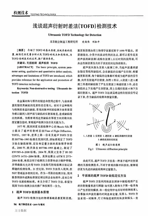
2. TOFD原理及系统组成2.1 TOFD原理是当超声波遇到诸如裂纹等的缺陷时,将在缺陷尖端发生叠加到正常反射波上的衍射波,探头探测到衍射波,可以判定缺陷的大小和深度。
TOFD原理当超声波在存在缺陷的线性不连续处,如裂纹等处出现传播障碍时,在裂纹端点处除了正常反射波以外,还要发生衍射现象。
衍射能量在很大的角度范围内放射出并且假定此能量起源于裂纹末端(图1。
这与依赖于间断反射能量总和的常规超声波形成一个显著的对比。
图11 =发射波2 =反射波3 =穿透波4 =顶部裂纹端衍射波5 =底部裂纹端衍射波除了发现由缺陷衍射的能量变化以外,TOFD方法也探测到一个直接穿过两个探针的表面(横向波和达到试块底部(测试对面没有受到缺陷干涉的底部反射波(图1中的注1和4。
图. 21- 横向波 2 - 顶部裂纹端衍射波3 - 底部裂纹端衍射波 4- 对面器壁反射波这种现象的研究产生了用于下列应用衍射波时差法无损检测方法:■探伤检验因为来自于缺陷范围的信号可记录。
衍射时差法TOFD和相控阵超声检测PAUT技术应用指南CCS衍射时差法TOFD(Time-of-Flight Diffraction)和相控阵超声检测PAUT(Phased Array Ultrasonic Testing)技术是目前非破坏检测中常用的超声波检测技术。
本文将介绍这两种技术的基本原理、应用领域和操作指南。
一、TOFD技术TOFD技术是一种全声程全记录的方法,通过检测超声波从缺陷的前端和后端边界发生的绕射波,通过分析绕射波到达的时差来确定缺陷的位置和大小。
TOFD技术具有以下特点:1.高灵敏度:TOFD技术能够检测到非常小的缺陷。
2.高精度:通过分析超声波的传播时差可以得到精确的缺陷位置和大小。
3.全声程扫描:TOFD技术能够扫描整个检测区域,不会遗漏任何可能的缺陷。
TOFD技术主要应用于以下领域:1.裂纹检测:TOFD技术能够准确地检测到各种裂纹,特别适用于高温、高压管道等环境下的裂纹检测。
2.焊缺陷检测:TOFD技术能够检测到焊缺陷的位置、大小和形态,对焊接质量的评估非常有帮助。
3.壳程检测:TOFD技术能够检测到壳程中的腐蚀、磨损等缺陷,有助于判断设备的安全性和可靠性。
TOFD技术的操作指南如下:1.设定扫描参数:包括扫描范围、扫描步长、发射和接收的超声波参数等。
2.放置探头:将探头与被检测物表面接触,并按照指定位置进行扫描。
3.开始扫描:根据设定参数开始扫描,同时记录采集到的数据。
4.数据分析:根据采集到的数据,分析缺陷的位置、大小和形态。
5.缺陷评定:根据分析结果进行缺陷的评定和分类。
二、PAUT技术PAUT技术是一种利用超声波的相位控制技术,通过控制多个发射和接收元件的相位差,达到改变超声波束的方向和焦点位置的目的,从而实现对被检测物的全面检测。
PAUT技术具有以下特点:1.快速扫描:PAUT技术能够快速地扫描整个检测区域。
2.高分辨率:通过控制超声波的发射和接收,可以实现高分辨率的检测。
衍射时差法超声检测技术(T O F D技术)第一章TOFD技术的基本知识 2018.11.301.衍射时差法:是采用一发一收探头对工作模式、主要利用缺陷端点的衍射波信号探测和测定缺陷位置及尺寸的一种超声检测方法。
2.缺陷的衍射信号与哪些因素无关?①与衍射信号的角度无关②与衍射信号的幅度无关因为衍射信号与角度和振幅无关,所以,TOFD技术在原理和方法上与传统脉冲反射超声波检测技术有根本性的区别。
3.传统超声检测技术是: 1、根据缺陷反射信号检出缺陷; 2、根据缺陷幅度评定缺陷尺寸4.传统超声检测技术影响缺陷的定量因素: 1、入射声束角度;2、检测方向; 3、缺陷表面粗糙度;4、工件表面状态;5、探头的压力。
5.TOFD仪器性能:1.更宽的接收放大系统频带;2.更快的数字化采样频率;3.更高的信号处理速度;4.更大的存储量6.TSG R0004-2009 《固定式压力容器安全技术监察规程》于2009年12月1日起施行,做出如下规定:无损检测人员应当按照相关技术规范进行考核取得相应资格证书后,方能承担与资格证书的种类和技术等级相对应的无损检测工作。
7.压力容器焊接接头无损检测方法的选择:压力容器的对接接头应当采用射线检测或者超声检测,超声检测包括衍射时差法超声检测(TOFD)、可记录的脉冲反射法超声检测(自动检测)和不可记录的脉冲反射法超声检测(手动检测);当采用不可记录的脉冲反射法超声检测(手动检测)时,应当采用射线检测或者衍射时差法超声检测做为附加局部检测;8.衍射现象:波在传播路径中遇到障碍物,发生绕过障碍物,产生偏离直线传播的现象,称为波的衍射。
衍射也是波在传输过程中与界面作用而发生的不同于反射的另一种物理现象。
9.裂纹的上下端点都可以产生衍射波。
衍射波信号比反射波信号弱得多,向空间的各个方向传播,没有明显的指向性、能量低、衍射方向不取决于入射角。
10.惠更斯-菲涅尔原理:惠更斯提出,介质上波阵面上的各点,都可以看成是发射子波的波源,其后任意时刻这些子波的包迹,就是该时刻新的波阵面。
国外超声波检测衍射时差法(带翻译)Time-of-flight diffraction (TOFD)The Time of Flight Diffraction (TOFD) ultrasonic testing method is relatively new and was first developed at Harwell laboratory in the late1977's by Maurice Silk. TOFD testing has been gaining in profile over the last three or four years with much interest focussing on whether or not it can be used to replace more established NDT methods. Recent survey shows that the annual average growth rate (AAGR) of the TOFD market is 10-20% higher than other NDT technique. The TOFD method is gaining and increasing popularity because of its high probability of detection, low false call rate, portability and most important its intrinsic accuracy in flaw sizing, especially in depth. There is another NDT method called radiography testing (RT/ X-ray) usually employed for flaw sizing. It should be noted that RT/X-ray technique shows better accuracy for lateral flaw sizing but it demonstrates insufficient accuracy in depth assessment. As the standards for radiation safety become tighter by the new European law, many NDT companies are trying to substitute X-ray technique by TOFD technique for cost effectiveness and mostly for safety and environment protection reasons.1 Theory and PrinciplesThe most significant distinction between TOFD and the other UT methods is that it monitors only forward-scattered diffracted energies from the tips of defects rather than reflected ultrasonic energies. Two wide beam angle probes are used in transmitter-receiver mode. Broad beam probes are used so that the entire crack area is flooded with ultrasound and, consequently, the entire volume is inspected using a single scan pass along the inspection line. Because the technique relies on detection of the forward scattered diffracted signals originating at the flaw edges, precise measurement of flaw size, location, and orientation is possible.Mr. Udo Schlengermann was one of the creators of the TOFD prestandardENV583 and was also involved in the development of the British standardBS7709.The principle of the TOFD techniques according to that report mention in the below:The TOFD method only evaluates diffracted echoes, which are 20dB less than the reflected echoes.●Diffracted waves have a different velocity than reflected longitudinal waves.●Diffraction is stronger for longitudinal waves than for shear waves.●The standard is the use of longitudinal probes, 50 to 70 degree, small crystal, withwidely spread sound beam to cover the whole defect.●The two diffracted signals of the crack tip are generated with a 180-degree phaseshift. The distance between the two signals on the time scale is nonlinear.●TOFD always uses RF signals to display images, (minus = black, plus = white),although colors could be used.Images showing arcs which shapes can be used to illustrated the geometry of the flaw.2ApplicationsThe TOFD technique can be used in the following fields:1. Quality control of pressure vessel fabrication and piping construction, e.g. Reactors, Spherical Tanks, etc.2. Periodic inspection of pressure vessels which do not facilitate entry due to presence of catalyst, internal lining or unavailability of shut-down window.3. The technique can be applied on hemispherical components and nozzle-shell/bead welds.4. In more recent years the expertise has been adapted for non nuclear applications including vessels for the chemical / process industries , complex forgings and castings (eg. turbine discs) and nodal configurations on tubular structures.3 Advantages and disadvantagesSo far, the following advantages have been recorded:1. TOFD defect detection does not depend on the defect orientation,in contrast to the pulse echo technique.2. Defect height can be exactly determined, thus most suitable formonitoring growth or changes in known defects.3. The inspection results are immediately available, as is a permanent record.4. Because of the high-test speed the costs are less than those for radiography for wall thickness above 25 mm. It possible to perform scans with a speed of hundreds of millimetre per second.5. TOFD save costs, if applied during construction, since it is possible to distinguish pre-service and in-service defects. That means the unit can stay longer in production, and is safe.6. High probability of defect detection.7. Most efficient for inspection of thick-walled vessels where X & Gamma ray would require too much time.8. TOFD method can be used to observe and report microscopic degradation caused by fatigue, stress and chemical attack - it has proven possible to quantify micro cracking caused by copper dilation through weld electrode contamination providing some knowledge of the probable fault mechanism is suspected prior to intervention.9. TOFD can be used in high temperature environment (up to 250 degrees C)10. The entire volume can be inspected using a single uni-axial pass along the length of the weld.11. TOFD is safe for environment protection reasons due to free radiation.The disadvantages of the TOFD method so far have been found are mentioned in the below:1. Sensitivity level: If the instrument sensitivity (gain) is set on very low level, the TOFD image would display no diffracted echo. If the instrument sensitivity is set just above electronic noise level, the TOFD image will display a lot of diffracted echoes which are caused by very small inhomogeneities of the weld seam and does not mean that the weld is really bad.2. Crack size determination: Crack tip echoes are part of a noise area caused by other relevant diffracted echoes of inhomogeneity. That can make sizing with the TOFD technique impossible. A TOFD image inspector needs to perform depiction decisions similar to that used in radiography.3. Detection of small cracks at backside: This is one of the main disadvantages of TOFD. For in-service inspection of welds it is usually not so important to find old defects inside the weld seam. More important is the detection of cracks at the backside of containers or piping. The use of diffracted echoes is for that task is not possible. So close to the back wall the crack tip echo amplitude is very small. In that case traditional UT techniques with angle beam probes and use of the mirror effect must be applied. The TOFD technique is not applicable here.4. A disadvantage of TOFD is that the gain must be very high, which produces a very high back wall echo and it is not suitable for coarse grained materials.5. The probe frequency should be 10 MHz or higher, frequencies under 5MHz are not applicable.6. Crack edges must be sharp, and they are not always.7. There is a dead zone for defect detection under the surface. It means, defects close to the surface could not be detected. This may be compensated by MPT (Magnetic Particle Test) or test with creeping wave probe.8. Minimum thickness requirement is 6mm with diameter of 4". No limitation on maximum thickness, it could be several hundreds milimeters.9. Cannot be applied on coarse-grain weldment e.g. austenitic stainless steel and Inconel.10. TOFD is not effective at detecting and sizing defect lying parallel to the inspection surface.11. TOFD cannot resolve 'included' defects such as fabrication induced slag and porosity.12. The problem is the angle of the crack cannot always be assumed to be vertical. The angle of the crack might have a great effect on the magnitude of return signals.超声波衍射时差法(TOFD)超声波衍射时差法(TOFD)的超声检测方法是比较新的,是第一次由毛里斯丝在1977下半年在哈威尔实验室发现的。