M000 0058 广域网接口与线缆(中文版V1.0)
- 格式:doc
- 大小:1.21 MB
- 文档页数:12

安装与配置快速指南R3000 Lite工业级双SIM卡VPN无线路由器包装清单在安装R3000 Lite路由器之前,请确认产品包装盒里是具备以下材料: Robustel R3000 Lite 路由器电源接线端子文档和软件CD可选配件AC/DC电源适配器SMA蜂窝网天线(3G/4G)串行线(DB9母头转DB9公头)35mm的DIN导轨安装套件或壁挂式安装工具*如果以上的物品缺少或者损坏请联系我们的销售人员环境要求电源输入:9 ~26 VDC功耗:空闲状态100 mA @ 12 V、通信状态400 mA(峰值) @12V工作环境温度:-40~ +85°C (R3000-L3E支持-20 ~ +75°C)工作环境湿度:5 ~95% RH第1章硬件接口介绍1.1概述如图所示,R3000 Lite路由器有一个以太网口(LAN口),一个DB9串行接口(支持RS232和RS485),两个蜂窝网SIM卡插槽,两个蜂窝网天线接口。
1.2外形尺寸设备外形尺寸:98 x 105 x 29.5 mm (长x宽x高)1.3 接口PIN 脚分配1.4 LED 指示灯1.5 重置按钮RSSI LED 灯 功能无 没有信号或SIM 卡安装不正确。
1 条 (只有第一个LED 灯亮) 信号等级: 1-10 (异常信号等级)。
2 条(第一个和第二个LED 灯亮) 信号等级: 11-20 (平均信号等级)。
3 条(所有RSSI LED 灯都亮) 信号等级: 21-31 (最佳信号等级)。
PIN 极性 10 正极 11 负极 12接地PIN 调试 RS232 RS485 (2-wire) 1 Data+ (A)2 RXD3 TXD4 DRXD5 GND GND6 Data- (B)7 RTS 8 CTS 9DTXD接口引脚分配PIN 功能 1 TX+ 2 TX- 3 RX+ 6RX-1.6以太网口以太网口有两盏LED指示灯。


云系列DAM0800-WIFI+网口版产品说明书云系列DAM0800-WIFI+网口版说明书V1.0北京聚英翱翔电子有限责任公司2016年01月目录一、产品说明 (1)二、产品特点 (1)三、产品功能 (1)四、产品选型 (1)五、主要参数 (1)六、通讯架构说明 (2)七、快速使用说明 (3)八、硬件说明 (3)1、接口说明 (3)2、继电器接线说明 (4)九、设备参数配置及测试..............................................................................错误!未定义书签。
十、设备唯一ID号........................................................................................错误!未定义书签。
1、扫描二维码获取................................................................................错误!未定义书签。
2、使用软件获取【选用】....................................................................错误!未定义书签。
十一、平台软件说明......................................................................................错误!未定义书签。
十二、开发资料说明. (4)1、工作模式说明 (7)2、Modbus寄存器说明 (7)3、相关指令 (8)4、指令详解 (9)十三、技术支持联系方式 (11)一、产品说明DAM0800设备是我公司云系列设备中网络版的一种,设备通过连接Internet广域网来进行通讯,使用我司配套的云平台软件可实现远程控制设备功能,每个设备具有唯一ID号方便用户进行二次开发使用。

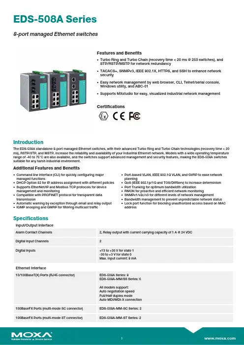
EDS-508A Series8-port managed EthernetswitchesFeatures and Benefits•Turbo Ring and Turbo Chain (recovery time <20ms @250switches),andSTP/RSTP/MSTP for network redundancy•TACACS+,SNMPv3,IEEE 802.1X,HTTPS,and SSH to enhance networksecurity•Easy network management by web browser,CLI,Telnet/serial console,Windows utility,and ABC-01•Supports MXstudio for easy,visualized industrial network managementCertificationsIntroductionThe EDS-508A standalone 8-port managed Ethernet switches,with their advanced Turbo Ring and Turbo Chain technologies (recovery time <20ms),RSTP/STP,and MSTP,increase the reliability and availability of your industrial Ethernet network.Models with a wide operating temperature range of -40to 75°C are also available,and the switches support advanced management and security features,making the EDS-508A switches suitable for any harsh industrial environment.Additional Features and Benefits•Command line interface (CLI)for quickly configuring major managed functions•DHCP Option 82for IP address assignment with different policies •Supports EtherNet/IP and Modbus TCP protocols for device management and monitoring•Compatible with PROFINET protocol for transparent data transmission•Automatic warning by exception through email and relay output •IGMP snooping and GMRP for filtering multicast traffic•Port-based VLAN,IEEE 802.1Q VLAN,and GVRP to ease network planning•QoS (IEEE 802.1p/1Q and TOS/DiffServ)to increase determinism •Port Trunking for optimum bandwidth utilization•RMON for proactive and efficient network monitoring•SNMPv1/v2c/v3for different levels of network management•Bandwidth management to prevent unpredictable network status •Lock port function for blocking unauthorized access based on MAC addressSpecificationsInput/Output InterfaceAlarm Contact Channels 2,Relay output with current carrying capacity of 1A @24VDC Digital Input Channels 2Digital Inputs+13to +30V for state 1-30to +3V for state 0Max.input current:8mAEthernet Interface10/100BaseT(X)Ports (RJ45connector)EDS-508A Series:8EDS-508A-MM/SS Series:6All models support:Auto negotiation speed Full/Half duplex modeAuto MDI/MDI-X connection100BaseFX Ports (multi-mode SC connector)EDS-508A-MM-SC Series:2100BaseFX Ports (multi-mode ST connector)EDS-508A-MM-ST Series:2100BaseFX Ports(single-mode SC connector)EDS-508A-SS-SC Series:2100BaseFX Ports,Single-Mode SC Connector,80kmEDS-508A-SS-SC-80Series:2Standards IEEE802.3for10BaseTIEEE802.3u for100BaseT(X)and100BaseFXIEEE802.1X for authenticationIEEE802.1D-2004for Spanning Tree ProtocolIEEE802.1w for Rapid Spanning Tree ProtocolIEEE802.1s for Multiple Spanning Tree ProtocolIEEE802.1Q for VLAN TaggingIEEE802.1p for Class of ServiceIEEE802.3x for flow controlIEEE802.3ad for Port Trunk with LACPOptical Fiber800Typical Distance4km5km40km80kmWavelength Typical(nm)130013101550TX Range(nm)1260to13601280to13401530to1570RX Range(nm)1100to16001100to16001100to1600Optical PowerTX Range(dBm)-10to-200to-50to-5RX Range(dBm)-3to-32-3to-34-3to-34Link Budget(dB)122929DispersionPenalty(dB)311Note:When connecting a single-mode fiber transceiver,we recommend using anattenuator to prevent damage caused by excessive optical power.Note:Compute the“typical distance”of a specific fiber transceiver as follows:Linkbudget(dB)>dispersion penalty(dB)+total link loss(dB).Ethernet Software FeaturesFilter802.1Q VLAN,Port-based VLAN,IGMP v1/v2,GVRP,GMRPIndustrial Protocols EtherNet/IP,Modbus TCPManagement IPv4/IPv6,SNMPv1/v2c/v3,LLDP,Port Mirror,Back Pressure Flow Control,BOOTP,DDM,DHCP Option66/67/82,DHCP Server/Client,Fiber check,Flow control,RARP,RMON,SMTP,SNMP Inform,Syslog,Telnet,TFTPMIB MIB-II,Bridge MIB,Ethernet-like MIB,P-BRIDGE MIB,Q-BRIDGE MIB,RMON MIBGroups1,2,3,9,RSTP MIBRedundancy Protocols STP,MSTP,RSTP,LACP,Link Aggregation,Turbo Chain,Turbo Ring v1/v2 Security HTTPS/SSL,TACACS+,Port Lock,RADIUS,SSHTime Management NTP Server/Client,SNTP,IEEE1588v2PTP(software-based)Switch PropertiesIGMP Groups256MAC Table Size8KMax.No.of VLANs64Packet Buffer Size1MbitsPriority Queues4VLAN ID Range VID1to4094LED InterfaceLED Indicators PWR1,PWR2,FAULT,10/100M(TP port),100M(fiber port),MSTR/HEAD,CPLR/TAIL Serial InterfaceConsole Port RS-232(TxD,RxD,GND),10-pin RJ45(115200,n,8,1)DIP Switch ConfigurationEthernet Interface Turbo Ring,Master,Coupler,ReservePower ParametersConnection2removable6-contact terminal block(s)Input Voltage12/24/48VDC,Redundant dual inputsOperating Voltage9.6to60VDCInput Current EDS-508A Series:0.22A@24VDCEDS-508A-MM/SS Series:0.30A@24VDCOverload Current Protection SupportedReverse Polarity Protection SupportedPhysical CharacteristicsHousing MetalIP Rating IP30Dimensions80.2x135x105mm(3.16x5.31x4.13in)Weight1040g(2.3lb)Installation DIN-rail mounting,Wall mounting(with optional kit)Environmental LimitsOperating Temperature Standard Models:-10to60°C(14to140°F)Wide Temp.Models:-40to75°C(-40to167°F)Storage Temperature(package included)-40to85°C(-40to185°F)Ambient Relative Humidity5to95%(non-condensing)Standards and CertificationsSafety EN60950-1,UL60950-1,CSA C22.2No.60950-1,UL508Hazardous Locations ATEX,Class I Division2EMC EN55032/24EMI CISPR32,FCC Part15B Class AEMS IEC61000-4-2ESD:Contact:6kV;Air:8kVIEC61000-4-3RS:80MHz to1GHz:20V/mIEC61000-4-4EFT:Power:2kV;Signal:1kVIEC61000-4-5Surge:Power:2kV;Signal:2kVIEC61000-4-6CS:10VIEC61000-4-8PFMFShock IEC60068-2-27Vibration IEC60068-2-6Freefall IEC60068-2-31MTBFTime1,043,909hrsStandards Telcordia(Bellcore),GBWarrantyWarranty Period5yearsDetails See /warrantyPackage ContentsDevice1x EDS-508A Series switchCable1x DB9female to RJ4510-pinInstallation Kit4x cap,plastic,for RJ45port2x cap,plastic,for SC fiber port(-SC models)2x cap,plastic,for ST fiber port(-ST models)Documentation1x quick installation guide1x warranty card1x product certificates of quality inspection,Simplified Chinese1x product notice,Simplified ChineseDimensionsOrdering InformationModel Name 10/100BaseT(X)Ports,RJ45Connector100BaseFX PortsMulti-Mode,SCConnector100BaseFX PortsMulti-Mode,STConnector100BaseFX PortsSingle-Mode,SCConnector100BaseFX PortsSingle-Mode,SCConnector,80kmOperating Temp.EDS-508A8––––-10to60°CEDS-508A-T8––––-40to75°C EDS-508A-MM-SC62–––-10to60°C EDS-508A-MM-SC-T62–––-40to75°C EDS-508A-MM-ST6–2––-10to60°C EDS-508A-MM-ST-T6–2––-40to75°C EDS-508A-SS-SC6––2–-10to60°C EDS-508A-SS-SC-T6––2–-40to75°CEDS-508A-SS-SC-806–––2-10to60°CEDS-508A-SS-SC-80-T6–––2-40to75°C Accessories(sold separately)Storage KitsABC-01Configuration backup and restoration tool for managed Ethernet switches and AWK Series wirelessAPs/bridges/clients,0to60°C operating temperaturePower SuppliesDR-120-24120W/2.5A DIN-rail24VDC power supply with universal88to132VAC or176to264VAC input byswitch,or248to370VDC input,-10to60°C operating temperatureDR-452445W/2A DIN-rail24VDC power supply with universal85to264VAC or120to370VDC input,-10to50°C operating temperatureDR-75-2475W/3.2A DIN-rail24VDC power supply with universal85to264VAC or120to370VDC input,-10to60°C operating temperatureMDR-40-24DIN-rail24VDC power supply with40W/1.7A,85to264VAC,or120to370VDC input,-20to70°Coperating temperatureMDR-60-24DIN-rail24VDC power supply with60W/2.5A,85to264VAC,or120to370VDC input,-20to70°Coperating temperatureSoftwareMXview-50Industrial network management software with a license for50nodes(by IP address)MXview-100Industrial network management software with a license for100nodes(by IP address)MXview-250Industrial network management software with a license for250nodes(by IP address)MXview-500Industrial network management software with a license for500nodes(by IP address)MXview-1000Industrial network management software with a license for1000nodes(by IP address)MXview-2000Industrial network management software with a license for2000nodes(by IP address)MXview Upgrade-50License expansion of MXview industrial network management software by50nodes(by IP address) Wall-Mounting KitsWK-46Wall-mounting kit,2plates,8screws,46.5x66.8x1mmRack-Mounting KitsRK-4U19-inch rack-mounting kit©Moxa Inc.All rights reserved.Updated March18,2022.This document and any portion thereof may not be reproduced or used in any manner whatsoever without the express written permission of Moxa Inc.Product specifications subject to change without notice.Visit our website for the most up-to-date product information.。
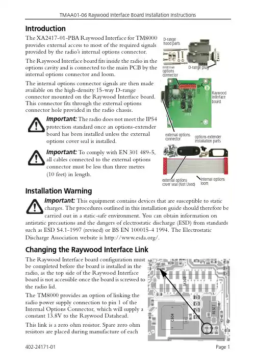
IntroductionThe XA2417-01-PBA Raywood Interface for TM8000 provides external access to most of the required signals provided by the radio’s internal options connector.The Raywood Interface board fits inside the radio in the options cavity and is connected to the main PCB by the internal options connector and loom.The internal options connector signals are then made available on the high-density 15-way D-rangeconnector mounted on the Raywood Interface board. This connector fits through the external options connector hole provided in the radio chassis.Installation WarningThis equipment contains devices that are susceptible to staticou can obtain information onantistatic precautions and the dangers of electrostatic discharge (ESD) from standards such as ESD S4.1-1997 (revised) or BS EN 100015-4 1994. The Electrostatic Discharge Association website is /.Changing the Raywood Interface LinkThe Raywood Interface board configuration must be completed before the board is installed in the radio, as the top side of the Raywood Interface board is not accessible once the board is screwed to the radio lid.The TM8000 provides an option of linking the radio power supply connection to pin 1 of the Internal Options Connector, which will supply a constant 13.8V to the Raywood Datahead.This link is a zero ohm resistor. Spare zero ohm resistors are placed during manufacture of eachThe radio does not meet the IP54 options cover seal is installed.T o comply with EN 301489-5, metres (10feet) in length.internal options connectorRaywood Interface boardD-range hood partsD-range plugoptions-extender installation partsinternal optionsloomexternal options cover seal (Not Used)external options connectorradio. Take one of these (located to the lower left of the Internal Options Connector), and place on location R786.Configuration ProcedureT o configure the board, carry out the following steps.1.Program the radio in which the Raywood Interface board is being installed with default settings. The default test settings are explained in the following tables .2.Disassemble the radio in order to gain access to the options cavity . For detailed disassembly instructions, refer to the disassembly procedure in the TM8100 Serv-ice Manual.3.Connect the internal options loom between SK102 on the Raywood Interface board and SK102 on the radio ’s main PCB.4.Set up the test equipment shown in, and follow the adjustment procedure for R V1 and R V2 described in the following section.PinDirection LabelActionActive Debounce Signal StateMirroredAUX_GPI2input 2BSETUP Enter Emergency Mode low 100None None AUX_GPI3input PWRSENSE Power Sense (ignition)high 10None None IOP_GPIO1input None T oggle Stand-by Mode low 0None None IOP_GPIO2input NoneExternal PTT1lowNoneNoneRx/PTT Type Tap Out Tap Out Type Tap OutUnmute Tap In Tap In Type Tap In Unmute Rx R2D-Split Busy Detect None A-Bypass In On PTT Mic PTT None C-Bypass Out On PTT None A-Bypass In On PTT EPTT1None C-Bypass Out On PTT T 8A-Bypass In On PTT EPTT2NoneC-Bypass OutOn PTTNone A-Bypass InOn PTTField Setting PTT Priority Highest Audio Source Audio T ap In FieldSetting Minimum Volume Level 255FieldSetting Command Mode Baud Rate 4800Command Mode Flow Control NoneData PortInternal OptionsAdjustment Points on the Raywood Interface BoardThe following table describes the Raywood Interface adjustment points. Adjustments are made by two variable resistors R V1 and R V2.Adjusting RV1, RV2RV1This adjusts the audio level from the radio to the Raywood datahead. T o adjust correctly apply an on channel RF carrier, modulated at 60% of full system deviation, using a1kHz tone. Use an audio meter on pins SK1.5 and SK1.14(GND) and adjust until the level of -7.3dBm is setRV2This adjusts the transmit deviation. Connect a 1kHz tone with a level of -11dBm to pins SK1.12 and SK1.14 (GND). Connect SK1.8 to ground this will cause the radio to transmit. Use a Radio Communications test set to measure deviation, adjust R V2 for 60% of full system deviation.Installing the Raywood Interface BoardThe following table describes the parts required to install an Raywood Interface board in a radio.Installation Procedure1.Disassemble the radio in order to gain access to the options cavity.For detailed disassembly instructions, refer to the disassembly procedure in the TM8100 Service Manual.2.Remove the top cover and lid b from the radio to access the options cavity.3.Remove the external options connector bung c , if it is fitted.4.On the inside of the radio lid place the foam seal d over the external options connector cavity e .5.With the top side of the Raywood Interface board f facing the radio lid, guide the external options connector g (the D-range connector on the Raywood Interface board) into the external options connector cavity.6.Screw the external options connector to the radio lid using the two screw-lock fasteners h . Tighten the fasteners to a torque of 0.9N ·m (8lbf ·in).Quantity Internal Part Number Description Reference1362-01111-00foam seald 2354-01043-00screw-lock fasteners h 4349-02062-00M3x8 screwsjThe external options connector screw-lock fasteners must bei.7.Screw the Raywood Interface board to the mounting posts on the radio lid using four M3x8 self-tapping screws j.Tighten the M3x8 screws to a torque of 1.9N·m (17lbf·in)8.Plug the unattached end of internal options connector loom 1)into the internaloptions connector on the radio main PCB.。


UDP8000M 系列说明书线性直流电源UDP8303M安全摘要UDP8000M 系列使用和储藏环境必须遵循的重要安全说明,为确保你的人身安全,在操作之前熟读以下操作说明,确保UDP8000M 系列在最佳的工作环境。
危险注意高压 接大地端子安全指南一般介绍不要阻挡和隔离机器的进风口和风扇通风口 避免严重碰撞或错误的用法导致机器损坏 不要对机器放静电非专业人员不要打开机器交流输入AC 输入电压:110V/120V/220V/230V ,50/60Hz 连接保护地线到大地,避免电击。
保险丝Model UDP8303M UDP8305M110V/120V T6.3AL/250V(20X5mm)T8AL/250V(20X5mm)220V/230VT3.15AL/250V(20X5mm)T4AL/250V(20X5mm)开机前确保使用正确的保险丝型号为防止火灾,要替换符合型号和额定值的保险丝 替换保险丝前不要连接电源线,以避免电击 替换保险丝前确定保险丝烧断的原因电源供应AC 输入电压110V/120V/220V/230V ±10%、50/60Hz 可根据实际需求通过后面板的"AC SELECTOR 选择不同的输入电源,切换输入电源电压前,请先断开电源连线,再拨到相应的档位。
、"UDP8000M 线性直流电源简介UDP8303M 直流电源具有三组独立输出:两组32V /3.2A 可调输出,一组固定可选输出:1.8V /2.5V /3.3V /5V /3A (可微调),具有CV 与CC 模式,短路与过压保护功能。
UDP8000M 主要特点:四位电压及电 流高精度显示 可设置过压与 过流保护输出电压/电流 设定查看远程控制(输出ON /OFF) USB _Device 通讯接口, 可用于软件升级, 上位机控制电源输出 Rs232接口M1~M5五组设置保存 与调用 关机记忆 键盘锁定智能的温控风扇 USB手机充电接口UDP8305M 直流电源具有三组独立输出:两组32V /5.2A可调输出,0-32V/3AUDP8303M主要指标参数测试条件:热机30分钟,温度+20℃~+30℃功能介绍一、电压和电流的设定和输出1.电压设定:按下CH1按钮,光标落在通道1的电压值上并闪烁,此时按下电压旋钮可 以使光标在电压值位上移动,连续按电压旋钮,光标可在电压值的最高位与最低位 之间循环移动,从而切换电压的粗调与细调,旋转电压旋钮便可调整电压值。

P/N: 1802055080023 *1802055080023*TN-5508A/5510A Series Quick Installation GuideMoxa ToughNet SwitchVersion 4.1, July 2021Technical Support Contact Information/support2021 Moxa Inc. All rights reserved.OverviewThe ToughNet TN-5508A/5510A series M12 managed Ethernet switches are designed for industrial applications in harsh environments. The TN Series switches use M12 connectors to ensure tight, robust connections, and guarantee reliable operation against environmental disturbances, such as vibration and shock. The wide 24 to 110 VDC with dual power input increases the reliability of your communications. The TN-5508A Series includes PoE and non-PoE switches.•TN-5508A Series: 8 Fast Ethernet M12 ports.•TN-5508A-8PoE Series: 8 PoE Fast Ethernet M12 ports.The TN-5510A Series also includes PoE and non-PoE switches.•TN-5510A-2GTX Series: 8 Fast Ethernet M12 ports, supports additional 2 Gigabit ports located on the bottom of the unit, with or without bypass function.•TN-5510A-2GLSX Series: 8 Fast Ethernet M12 ports, supports additional 2 Gigabit fiber ports located on the bottom of the unitwith embedded multi-mode Q-ODC® interface.•TN-5510A-8PoE-2GTX Series: 8 PoE Fast Ethernet M12 ports, supports additional 2 Gigabit ports located on the bottom of theunit, with or without bypass function.•TN-5510A-8PoE-2GLSX Series: 8 PoE Fast Ethernet M12 ports, supports additional 2 Gigabit fiber ports located on the bottom of the unit with embedded multi-mode Q-ODC® interface.The -40 to 75°C operating temperature and IP54 rated waterproof enclosure allow deployment in harsh environments. The TN-5508A/5510A Series Ethernet switches are compliant with mandatory sections of the EN 50155 standard covering operating temperature, power input voltage, surge, ESD, and vibration, as well as conformal coating and power insulation, making the switches suitable for a variety of industrial applications.Package ChecklistYour ToughNet TN-5508A/5510A switch is shipped with the following items. If any of these items is missing or damaged, please contact your customer service representative for assistance.• 1 Moxa ToughNet switch.•Panel mounting screws.•Quick installation guide (printed).•Warranty card.FeaturesAnti-Vibration Circular Connectors for Robust Links•M12 D-coding 4-pin female connectors for Fast Ethernet 10/100BaseT(X) ports.•M12 X-coded 8-pin female connectors for Gigabit Ethernet 10/100/1000BaseT(X) ports•Fiber-optic ODC connectors with embedded 2 km Gigabit Ethernet 1000BaseLSX ports•M12 A-coding 5-pin male connectors for console and relay output. •M23 6-pin male connectors for power input.Isolated Power Inputs•Supports 24-110 VDC (16.8 to 137.5 VDC).High Performance Network Switching Technology•IPv6 ready, certified by the IPv6 Logo Committee.•IEEE 1588 PTP (Precision Time Protocol) for the precise time synchronization of networks.•DHCP Option 82 for IP address assignment with different policies. •EtherNet/IP and Modbus/TCP industrial Ethernet protocols supported.•Turbo Ring and Turbo Chain (recovery time <20 ms @250 switches),and STP/RSTP/MSTP for network redundancy•IGMP Snooping and GMRP for filtering multicast traffic.•Port-based VLAN, IEEE802.1Q VLAN, and GVRP protocol to ease network planning.•QoS (IEEE 802.1p/1Q and ToS/DiffServ) allows real-time traffic classification and prioritization.•IEEE 802.3ad, LACP for optimum bandwidth utilization. •TACACS+, SNMPv3, IEEE 802.1X, HTTPS, and SSH to enhance network security•SNMP v1/v2c/v3 for different levels of network management. •RMON for efficient network monitoring and proactive capability. •Bandwidth management prevents unpredictable network status. •Lock port allows access by only authorized MAC addresses.•Port mirroring for online debugging.•Automatic warning by exception through email, relay output. •Automatic recovery of connected devices’ IP addresses.•Line-swap fast recovery.•LLDP for automatic topology discovery through network management software.•Loop protection prevents network loops•Configurable through Web browser, Telnet/Serial console, CLI, and Windows utility.Designed for Industry-specific Applications•Two Gigabit Ethernet ports to meet high bandwidth requirements. •Bypass relay option on the 2 Gigabit Ethernet ports ensure non-stop data communication in the event a switch stops working due to a power failure.•Complies with all EN 50155 mandatory test items*•-40 to 75°C operating temperature range.•IP54 rugged high-strength case.•Panel mounting or DIN-Rail mounting installation capability.*This product is suitable for rolling stock railway applications, as defined by the EN 50155 standard. For a more detailed statement, click here: /doc/specs/EN_50155_Compliance.pdf Recommended Optional Accessories•CBL-M23(FF6P)Open-BK-100-IP67: 1-meter M23 to 6-pin power cable with IP67-rated female 6-pin M23 connector.•CBL-M12D(MM4P)/RJ45-100 IP67: 1-meter M12-to-RJ45 Cat-5E UTP Ethernet cable with IP67-rated male 4-pin M12 D-codedconnector.•CBL-M12DMM4PM12DMM4P-BK-100-IP67: 1-meter M12-to-M12 Cat-5E STP Ethernet cable with waterproof 4-pin D-coded M12connector.•CBL-M12(FF5P)/OPEN-100 IP67: 1-meter M12-to-5-pin power cable with IP67-rated female 5-pin M12 A-coded connector.•CBL-M12(FF5P)F9-BK-150: 1.5-meter M12-to-DB9 Cat-5E STP Ethernet cable with waterproof 5-pin D-coded M12 connector. •CBL-M12XMM8P-Y-100-IP67: 1-meter M12-to-M12 Cat-5 UTP Ethernet cable with IP67-rated 8-pin male X-coded crimp type M12 connector.•CBL-M12XMM8P-Y-300-IP67: 3-meter M12-to-M12 Cat-5 UTP Ethernet cable with IP67-rated 8-pin male X-coded crimp type M12 connector.•CBL-M12XMM8PRJ45-Y-200-IP67: 2-meter M12-to-RJ45 Cat-5 UTP Ethernet cable with IP67-rated 8-pin male X-coded crimp type M12 connector.•M12D-4P-IP68: Field-installable M12 D-coded screw-in connector, male 4-pin, IP68-rated.•M12A-5P-IP68: Field-installable M12 A-coded screw-in connector, female 5-pin, IP68-rated.•M12X-8PMM-IP67-HTG: Field-installable M12 X-coded crimp type, slim design connector, male 8-pin, IP67-rated•CAP-M12F-M: Metal cap for M12 female connector.•ABC-01-P-M12-CT-T:Configuration backup and restoration tool with M12 connector for ToughNet Series EN 50155 managed Ethernet switches, -40 to 75°C operating temperature.TN-5508A/5510A Panel Layouts1.Model name.2.Console port.3.Relay output port.4.Power input port (male 5-pin shielded M23 connector).5.10/100BaseT(X) port (M12 D-coded 4-pin female connector)6.PWR1 LED: for power input 1.7.PWR2 LED: for power input 2.8.FAULT LED.9.MSTR/HEAD LED: for ring master or chain head.10.CPLR/TAIL LED: for ring coupler or chain tail.11.E1 LED: Not used by the TN-5508A/TN-5508A-8PoE series.12.E2 LED: Not used by the TN-5508A/TN-5508A-8PoE series.13.TP port’s 10/100 Mbps LED.14.Screw holes for panel mounting kit.15.Grounding screw16.Waterproof vent.17.Product label.18.Screw holes for DIN-Rail mounting kit.19.Gigabit Ethernet port E1 (corresponding to port 9 in the TN-5510AUser's Manual) (For TN-5510A-2GTX/TN-5510A-8PoE-2GTXSeries).20.Gigabit Ethernet port E2 (corresponding to port 10 in the TN-5510A User's Manual) (For TN-5510A-2GTX/TN-5510A-8PoE-2GTX Series).21.Gigabit fiber port E1 (corresponding to port 9 in the TN-5510AUser’s Manual) (For TN-5510A-2GLSX/TN-5510A-8PoE-2GLSXSeries).22.Gigabit fiber port E2 (corresponding to port 10 in the TN-5510AUser’s Manual) (For TN-5510A-2GLSX/TN-5510A-8PoE-2GLSX Series).Mounting Dimensions (unit = mm) TN-5508A SeriesPanel/Wall MountingSTEP 1:Mounting the TN-5508A/5510A to a wall requires 4 screws. Use the ToughNet switch as a guide to mark the correct positions of the 4 screws.STEP 2:Use the 4 screws in the panelmounting kit. If you would like touse your own screws, make surethe screw head is between 6.0 mm and 7.0 mm in diameter andthe shaft is less than 4.0 mm indiameter, as shown at the right. Do not screw the screws in all the way—leave a space of about 2 mm to allow room for sliding the ToughNet switch between the wall and the screws. NOTE Before tightening the screws into the wall, make sure the screw head and shaft size are suitable by inserting the screw through one of the keyhole-shaped apertures of the ToughNet switch.STEP 3:Once the screws are fixed in the wall, hang the ToughNet switch on the 4 screws through the large opening of the keyhole-shaped apertures, and then slide the switch downwards. Tighten the four screws for added stability.NOTETo provide greater protection from vibrations and shocks, use screws with shaft diameter between 6.0 mm and 7.0 mm, and fix the ToughNet switch onto the wall directly through the large opening of the keyhole-shaped apertures.DIN-Rail Mounting (optional)With the optional DIN-Railmounting kit DK-DC50131 (mustbe purchased separately), youcan mount the TN-5508A/5510Aon a 35mm DIN-Rail.STEP 1:Use 12 screws (6 screws perplate) to attach the two DIN-Railattachment plates to the rearpanel of the switch. STEP 2:If the spring-loaded bracket is locked in place, push the recessed button to release it. Once released, you should feel some resistance from the spring as you slide the bracket up and down a few millimeters in each direction.STEP 3:Position the ToughNet switch ontheDIN-Rail, tilting to hook clamps overthe top edge of the rail. STEP 4: Swing the switch down fully onto the DIN-Rail, until both clamps completely latch.To remove the Moxa ToughNet Switch from theDIN-Rail, use a screwdriver to pull out the twospring-loaded brackets from the bottom untilthey are fixed in the “locked” position. Thenreverse Step 3 and 4 above.Wiring RequirementsPlease read and follow these guidelines:•Use separate paths to route wiring for power and devices. If power wiring and device wiring paths must cross, make sure the wires are perpendicular at the intersection point.NOTE Do not run signal or communications wiring and power wiring through the same wire conduit. To avoid interference, wireswith different signal characteristics should be routed separately. •You can use the type of signal transmitted through a wire to determine which wires should be kept separate. The rule of thumb is that wiring that shares similar electrical characteristics can bebundled together.•Keep input wiring and output wiring separated.•It is strongly advised that you label wiring for all devices in the system when necessary.Grounding the ToughNet SwitchGrounding and wire routing help limit the effects of noise due to electromagnetic interference (EMI). Run the ground connection from the grounding screw to the grounding surface prior to connecting devices.Connecting the Power SuppliesThe ToughNet TN-5508A/5510A Series switches support two sets of power input—power input 1 and power input 2. The M23 6-pin male connector on the TN-5508A/5510A Series switches’ front panel is used for the dual power inputs.Pinouts for the power input port on the TN-5508A/5510APinDescription Usage 1 PWR1 Live / DC + Connect “PWR1 Live / DC +” to the positive (+) terminal when using a DCpower source.2 PWR1 Neutral / DC - Connect “PWR1 Neutral / DC -” to thenegative (-) terminal when using a DCpower source. The negative inputs for thetwo power supplies are N1/V- and N2/V-.3 Chassis Ground Connect the “Chassis Ground” to theequipment ground bus for DC inputs.4 PWR2 Neutral / DC -Connect “PWR2 Neutral / DC -” to thenegative (-) terminal when using a DCpower source. The negative inputs for thetwo power supplies are N1/V- and N2/V-.PinDescription Usage 5 PWR2 Live / DC + Connect “PWR2 Live / DC +” to the positive (+) terminal when using a DCpower source.STEP 1:Plug your power cord connector to the power input port of the TN-5508A/5510A switch.STEP 2:Screw the nut on your power cord connector to the power input connector on the switch to ensure a tight connection.Connecting the Relay OutputsEach TN-5508A/5510A switch has two sets of relay outputs—relayoutput 1 and relay output 2.The M12 A-coded 5-pin male connector on the TN-5508A/5510A front panel is used for the two relay outputs. Use a power cord with an M12 A-coded 5-pin female connector to connect the relay contacts. You can purchase an M12 power cable from Moxa.Pinouts for the relay output port on TN-5508A/5510AN.C.: Not connected FAULT:The two sets of relay contacts of the M12 A-coded 5-pin male connector are used to detect user-configured events. The two wires attached to the fault contacts form an open circuit when a user-configured event is triggered. If a user-configured event does not occur, the fault circuit remains closed.Connecting the Data Lines10/100BaseT(X) Ethernet Port ConnectionAll TN-5508A/5510A models have 8 10/100BaseT(X) Ethernet ports (M12 D-coded 4-pin female connector). The 10/100TX ports located on the TN-5508A/5510A front panel are used to connect to Ethernet-enabled devices. Most users configure these ports for Auto MDI/MDI-X mode, in which case the port’s pinouts are adjusted automatically depending on the type of Ethernet cable used (straight-through or cross-over), and the type of device (NIC-type or HUB/Switch-type) connected to the port.In what follows, we give pinouts for both MDI (NIC-type) ports and MDI-X (HUB/Switch-type) ports. We also give cable wiring diagrams for straight-through and cross-over Ethernet cables.Pinouts for the 10/100BaseT(X) Ports on the TN-5508A/5510A.Housing: shieldPinouts for the 10/100/1000BaseT(X) M12 (8-pin) PortM12 (4-pin, M) to M12 (4-pin, M) Cross-Over Cable WiringM12 (4-pin, M) to M12 (4-pin, M) Straight-Trough Cable WiringM12 (4-pin, M) to RJ45 (8-pin) Cross-Over Cable WiringM12 (4-pin, M) to RJ45 (8-pin) Straight-Trough Cable WiringBypass Relay FunctionThe TN-5510A-2GTXBP and TN-5510A-8PoE-2GTXBP models’ twoGigabit Ethernet ports are equipped with a bypass relay function. When the switch is operating normally, these two Gigabit ports work in the same way as the other ports. That is, frame ingressions are processed and then forwarded. In the event the switch stops working due to a power failure, the bypass relay function will be triggered to ensure non-stop data communication.The figure below illustrates the bypass relay function. For example, if Switch B loses power, then the two Gigabit ports will be bypassed through the relay circuit and the transmission line from Switch A to B and the transmission line from Switch B to C will interconnect automatically; this way there is no stoppage.The bypass relay function helps the network recover from single-node failures in a linear topology.With the maximum segment length of category 5 twisted-pair cable being 100 meters, cable length must be considered when designing a network that utilizes this function. For example, the total length of the cables from Switch A to B and from B to C must be no more than 100 meters. This way, if the two adjacent nodes (switch B and C for example) encounter a power failure, there will be no stoppage,provided that the total length of the cables A-to-B, B-to-C, and C-to-D are no more than 100 meters.The bypass relay function works best for networks with lineartopologies. ToughNet™ switches with bypass relay function are not recommended to be used in networks that employ ring topologies because network loops may occur when redundancy protocols such as RSTP or TurboRing™ are applied.LED IndicatorsSeveral LED indicators are located on the ToughNet switch’s front panel. The function of each LED is described in the table below. LEDColor StateDescriptionSystem LEDsPWR1 AMBER ON Power is being supplied to power input PWR1.OFF Power is not being supplied to power input PWR1PWR2 AMBER ON Power is being supplied to power input PWR2.OFF Power is not being supplied to power input PWR2.BypassingSwitch A Switch B Switch C Switch DLED Color State DescriptionFAULT RED ONWhen the corresponding PORT alarmis enabled, and a user-configuredevent is triggered.OFFWhen the corresponding PORT alarmis enabled and a user-configuredevent is not triggered, or when thecorresponding PORT alarm isdisabled.MSTR/ HEAD GREENONWhen the TN switch is either theMaster of this Turbo Ring, or theHead of this Turbo Chain.BlinkingWhen the TN switch is Ring Master ofthis Turbo Ring and the Turbo Ring isbroken, or it is Chain Head of thisTurbo Chain and the Turbo Chain isbroken.OFFWhen the TN switch is neither theMaster of this Turbo Ring, nor theHead of this Turbo Chain.CPLR/ TAIL GREENONWhen the TN switch enables thecoupling function to form a back-uppath in this Turbo Ring, or it is theTail of this Turbo Chain.Blinking When Turbo Chain is down.OFFWhen the TN switch disables thecoupling function of Turbo Ring, or itis not the Tail of the Turbo Chain.TP (10/100M) AMBERON TP port’s 10 Mbps link is active.Blinking Data is being transmitted at 10 Mbps.OFF TP port’s 10 Mbps link is inactive. GREENON TP port’s 100 Mbps link is active.BlinkingData is being transmitted at 100Mbps.OFF TP port’s 100 Mbps link is inactive.PoE Ports AMBER ONPower is being supplied to a PoweredDevice (PD)OFFPower is not being supplied to aPowered Device (PD)E1/E2 (10/100/1 000M) AMBERONTP port’s 10 or 100 Mbps link isactive.BlinkingData is being transmitted at 10 or100 Mbps.OFFTP port’s 10 or 100 Mbps link isinactive.GREENON TP port’s 1000 Mbps link is active.BlinkingData is being transmitted at 1000Mbps.OFF TP port’s 1000 Mbps link is inactive.Support and AssistanceVisit our website at https:///en/support where you can find the latest information about the product.。

M580系列产品培训演讲人:Modicon 084Modicon 584Modicon M340Modicon M5801968:世界上第1台可编程控制器1998:世界上第1台带网页服务的控制器2007:紧凑型可编程自动化控制器(PAC)2014:第一台以太网可编程自动化控制器1985:模块化机架安装&紧凑型控制器2004: Modicon PAC 统一软件平台Unity Pro Modicon Quantum / PremiumModicon M3401994:可编程自动化控制器(PAC)1979:第1个工业现场总线Modicon 984安全性灵活性高效性连通性更多数据更多设备更多处理流程信息安全高可用性高可靠性随时随地不停机更改,以适应多变的需求可重用知识透明访问资产的能源和过程数据MODICON 50年-引领自动化创新之路2015:以太网可编程自动化冗余控制器Modicon M580冗余Modicon M580SSIL3Modicon M580S 冗余SIL32017:以太网可编程自动化安全型控制器2019:以太网可编程自动化冗余安全控制器目录1简介2底板34CPU 模块5电源模块67通信模块8特殊功能模块I/O 模块网络架构9编程软件MODICON ePAC 通信模块-远程I/O 接口模块(CRA)●高性能版CRA (有涂层版本)●最突出特点, 10ms 系统时间戳●Ethernet BMECRA31210支持“Ethernet only” 模块: HART 模块, 称重模块和嵌入式DRS 模块●标准版CRA●优化成本●仅提供基本功能●服务端口●担任Modbus/TCP 服务器●担任CIP 显示报文服务器BMX CRA31200标准型BMX CRA31210高性能型BMECRA31210高性能型时间戳10 ms CCOTF 总线X 背板兼容专家模块最大模拟I/O 最大数字I/O 服务端口ETH 背板兼容No No Yes No16128No Yes Yes Yes Yes2561024YesYes Yes Yes No Fast 和辅助任务No Yes Yes Ethernet only 模块NoNo YesMODICON ePAC 通信模块-工业以太网模块BME NOC standard BME NOC advancedRouterIO Data size (bytes) Support EtherNet/IP Support Modbus/TCP Web server classYes8K In+8K OutYesB C CYesBME NOCcontrol●以太网模块NOC●标准以太网模块BMENOC0301带基础网络服务●高级以太网模块BMENOC0311带FactoryCast●控制网络以太网模块BMENOC0321Control带路由功能●BMENOC03X1 集成3个以太网端口:●2 个DIO 端口,1 个服务端口●Modbus/TCP●EtherNet/IP●可选择是否与以太网背板连接NoMODICON ePAC通信模块-IEC61850模块●支持单机和冗余系统使用●IEC 61850 服务BMENOP0300(C)●MMS 报文服务器和客户端●GOOSE 发布和订阅●遵从IEC 61850 Ed 2.0 ,也可以配置为Ed 1.0●16 个逻辑设备●MMS 服务器: 16 个连接,64 个报告控制块实例,每个报告控制块8个实例,68个数据集,256个数据属性/数据集,URCB和BRCB报告。
安装说明Micro800 8 点输入和 8 点输出 AC 模块目录号 2085-IA8、2085-IM8、2085-OA8/literature/目录主题页码重要用户须知2其它资源5概述5模块描述6安装模块6输出接线8技术参数9重要用户须知固态设备具有与机电设备不同的运作特性。
Safety Guidelines for the Application, Installation and Maintenance of Solid State Controls(出版物SGI-1.1),可以由您当地的罗克韦尔自动化销售部提供,或通 过互联网地址/literature/下载)介绍了固态设备和硬接线机电设备之 间的一些重要区别。
由于存在这些区别,同时由于固态设备的广泛应用,负责应用此设备的所有人员都必须确保仅以可接受的方式应用此设备。
对于由于使用或应用此设备而导致的任何直接或间接的损害,罗克韦尔自动化公司在任何情况下都不承担任何责任。
本手册中的示例和图表仅供说明之用。
由于任何特定的安装都存在很多变异因素和要求,罗克韦尔自动化公司对于依据这些示例和图表所进行的实际应用不承担任何责任和义务。
对于因使用本手册中所述信息、电路、设备或软件而引起的专利问题,罗克韦尔自动化不承担任何责任。
未经罗克韦尔自动化公司的书面许可,禁止复制本手册的全部或部分内容。
出版物 2085-IN005A-ZH-P - 2012 年 9 月出版物 2085-IN005A-ZH-P - 2012 年 9 月环境与机壳防止静电放电注意: 本设备适用于污染等级 2 工业环境、过电压 II 类应用(IEC 60664-1 中有规定)以及最高 2000 m (6562 ft) 的海拔高度,而不导致额定值降低。
按照 IEC/CISPR 11 的规定,本设备属于组 1,A 类工业设备。
若不采取适当预防措 施,则可能会因传导和辐射干扰而很难确保它们在住宅环境和其它环境下的电磁兼容性。
Micro800 可编程控制器系列Bulletin 2080、20852罗克韦尔自动化出版物 2080-SG001G-ZH-P - 2022 年 11 月Micro800 可编程控制器系列 选型指南罗克韦尔自动化认识到,目前我们行业和本出版物中使用的一些条款不符合技术中包容性语言的发展趋势。
我们正积极与行业同行合作,寻找此类条款的替代方案,对产品和内容进行更改。
在我们尚未完成实施这些更改之前,请不要使用我们内容中的这些条款。
目录最新产品本出版物中包含以下新增内容或更新信息。
该列表仅列出了主要更新,并未反映出所有变更。
并非每次修订都提供有翻译版本。
主题页码最新产品2Micro800 控制器概述3Micro800 控制器比较4选择 Micro810 控制器8选择 Micro820 控制器9选择 Micro830 控制器10选择 Micro850 控制器11选择 Micro870 控制器12选择 Micro800 扩展 I/O 模块13选择 Micro800 功能性插件模块和附件14其他资源17主题页码添加了有关支持 Kinetix 5100 和 PowerFlex 520 系列变频器用于固件版本为 21.011 或更高版本的 Micro850 (2080-L50E) 和 Micro870 (2080-L70E) 控制器的信息3在 Micro800 产品目录输入/输出数量和类型表中添加了以太网节点列6在 Micro850 产品目录输入/输出表中添加了以太网节点列11、12在 Micro870 产品目录输入/输出表中添加了以太网节点列13罗克韦尔自动化出版物 2080-SG001G-ZH-P - 2022年 11 月3Micro800 可编程控制器系列 选型指南Micro800 控制器概述Micro800™ 控制器设计用于经济型单机控制。
根据基座中内置 I/O 点数的不同,这些经济的小型可编程逻辑控制器 (PLC)具有不同的配置,其拥有的一系列特性足以满足不同的需求。
Installation InstructionsRJ45 Splitter Cable (Catalog No. AK-UO-RJ45-SC1)for use with DSI/ MDI Drive ProductsImportant:For connectivity guidelines relating to all configurations, see next page.and One Permanent PeripheralConnecting an RS-485 NetworkPanel Mount UnitParameter 9 [Device Type] set to "Master" and connected to Master Serial ConverterPanel Mount UnitAK-U0-RJ45-TB2PConnectivity GuidelinesRefer to the drive user manual for specific DSI / MDI accessory part numbers.!ATTENTION: Risk of injury or equipment damage exists. The peripherals may not perform as intended if these Connectivity Guidelines are not followed. Precautions should be taken to follow these Connectivity Guidelines.•Two peripherals maximum can be attached to a drive.•If a single peripheral is used, it must be connected to the Master port (M) on the splitter and configured for “Auto” (default) or “Master.” Parameter 9 [Device Type] on the DSI / MDI keypads and Parameter 1 [Adapter Cfg] on the Serial Converter are used to select the type (Auto / Master / Slave).•Do not use the RJ45 Splitter Cable with a drive that has an internal networkcommunication adapter installed. Since only one additional peripheral can be added, the second peripheral can be connected directly to the RJ45 port on the drive. The internal Comm is always the Master, therefore the external peripheral must be configured as “Auto” (for temporary connections) or “Slave” (for permanent connections).•If two peripherals will be powered up at the same time, one must be configured as the “Master” and connected to the Master port (M) and the other must be connected as the “Slave” and connected to the Slave port (S).Publication RA-IN003A-EN-P – October, 2002P/N 316515-P01Copyright © 2002 Rockwell Automation, Inc. All rights reserved. Printed in USA.。
3.1 广域网接口与线缆3.1.1 广域网的类型WAN●窄带广域网→PSTN:Public Switched Telephone Network,公共交换电话网→ISDN:Integrated Services Digital Network,综合业务数字网→DDN:Digital Data Network,数字数据网→帧中继:Frame Relay→X.25:公用分组交换网●宽带广域网→ATM:异步传输模式→SDH:同步数字系列广域网(Wide Area Network)是一种跨越大的地域的网络。
目前有多种公共广域网络。
一般我们的网络会通过服务商提供的具体业务连接到广域网络上。
按其提供业务的带宽的不同,可简单的分为窄带广域网和宽带广域网两大类。
现有的窄带公共网络包括PSTN 公共交换电话网、ISDN 综合数字业务网、DDN、X.25 网、帧中继(Frame Relay)网等。
PSTN 可能是我们接触最多的公共窄带网络,目前主要提供电话和传真业务,通过调制解调器可以完成一些有限的数据传输业务。
ISDN 综合业务数字网将在本章后面小节专门介绍。
DDN 即数字数据网,是一种广泛使用的基于点对点连接的窄带公共数据网络。
X.25 网是一种国际通用的标准广域网,基于分组交换技术,内置的差错纠正、流量控制和丢包重传机制,使之具有高度的可靠性,适于长途噪声线路。
X.25网络刚被引入时,其最大速率仅为有限的64Kbps ,使之可提供的业务非常有限。
1992年,ITU-T更新了X.25标准,其传输速度可高达2Mbps。
X.25网络在传输数据时,沿途每个节点都要重组包,使得数据的吞吐率很低,包时延较大。
X.25显然不适于传输质量好的信道。
Frame Relay 帧中继是一种应用很广的服务,采用E1 电路,速率可从64K到2M,速率较快,它减少了差错检测,充分利用了如今广域网连接中比较简洁的信令。
中间节点的延迟比X.25 网小得多。
帧中继的帧长度可变,可以方便的适应LAN 中的任何包或帧,提供了对用户的透明性。
帧中继容易受到网络拥塞的影响,对于时间敏感的实时通信没有特殊的保障措施,当线路受到噪声干扰时,将引起包的丢弃。
现在的宽带网络一般有ATM和SDH两种。
ATM 即异步传输模式,为在交换式WAN 或LAN 骨干网以及高速传输数据提供了通用的通信机制,它同时支持多种数据类型(话音、视频、文本等)。
与传统WAN 不同,ATM 是一种面向连接的技术,在开始通信之前,将首先建立端到端的连接。
ATM 最突出的优势之一,就是支持QoS (Quality of Service) 。
SDH 是目前应用最广的光传输网络,带宽高,抗干扰性强,可扩展性较强。
在具体的网络连接上一般服务商将线缆布放到用户处,用户将该线缆与一个调制设备(普通调制解调器、DTU或基带调制解调器)相连,然后我们的网络边缘设备(一般为路由器)再与调制设备相连。
但有些线路路由器内部设有内置的设备,可以直接连接服务商布放的线缆,如E1/ATM等。
3.1.2 异步串口与同步串口异步& 同步串口●异步串口→两种异步串口:异步串口分为设置成异步方式的同/异步串口和专用异步串口→异步串口可以设为专线方式和拨号方式,常用的是拨号方式●同步串口→可以工作在DTE和DCE两种方式→可以外接多种类型电缆→支持多种链路层协议→支持IP和IPX网络层协议→show interface serial命令可显示同步串口的信息广域网按照线路类型来分有X.25网、帧中继网、ATM网、ISDN网等类型。
路由器因此也相应地有同/异步串口、ATM接口、ISDN BRI接口、cE1/PRI接口等等。
目前VRP支持的中低端路由器的WAN接口包括异步串口、同步串口、ISDN BRI接口及cE1/PRI接口。
VRP中有两种异步串口,一种是将同/异步串口设置为工作在异步方式,接口名称为Serial;另外一种是专用异步串口,接口名称为Async。
异步串口可以设为专线方式和拨号方式。
在应用中更常用的是拨号方式,异步串口外接Modem或ISDN TA(T erminal Adapter,终端适配器)时可以作为拨号接口使用,封装链路层协议SLIP或PPP,支持IP和IPX等网络协议。
同步串口特性:可以工作在DTE和DCE两种方式,一般情况下,路由器的同步串口工作在DTE方式,接受DCE设备提供的时钟。
同步串口可以外接多种类型电缆,如V.24和V.35等。
VRP可以自动检测同步串口外接电缆类型,并完成电气特性的选择,一般情况下,无需手工配置。
同步串口支持的链路层协议包括PPP、帧中继、LAPB和X.25等。
支持IP和IPX网络层协议。
可以通过执行show interface serial命令查看同步串口的当前外接电缆类型以及工作方式(DTE/DCE)等信息,关于该命令的使用在后续课程中间有详细介绍。
3.1.3 V.24接口规程V.24规程的机械特性●DB50(路由器端)--DB25(外接网络端)●可工作在同步和异步两种方式下●异步工作方式下最高传输速率是115200bps●同步方式下最高传输速率为64000bpsV.24 接口规程的介绍中,将以Quidway 系列路由器的常用接口为例从机械特性、电气特性、常用控制信号、传输速率、传输距离和接口电缆六个方面来讲解。
这几个方面也是其它规程所关心的重要内容之一。
机械规程包括对接口的物理管脚数目、排列定义以及标准尺寸等方面的定义。
Quidway 系列路由器使用V.24 接口电缆外观如图所示,路由器端为DB50 专用插头,外接端是标准DB25 接头,符合EIA-RS-232 接口标准,电缆可以工作在同步和异步两种方式下,所以既可以与普通的模拟Modem、ISDN 终端适配器等以拨号方式进行异步连接,也可以连接基带Modem 进行同步连接。
异步工作方式下,封装链路层协议PPP,支持网络层协议IP和IPX,最高传输速率是115200bps,同步方式下,可以封装X.25、帧中继、PPP、HDLC、SLIP 和LAPB 等链路层协议,支持IP和IPX,而最高传输速率仅为64000bps 。
V.24规程的机械特性DB50(路由器端)--DB25(外接网络端)V.24 电缆接口分DCE 和DTE 两侧,分别对应数据电路端接设备(网络侧)和数据终端设备(用户侧)。
对应的DCE 侧为插座(25孔),DTE 侧为插头(25针)。
通信的双方相对而言,路由器属于DTE 侧设备,各种Modem 、ISDN 终端适配器等则属于DCE 设备。
本图所示为Quidway 系列路由器V.24 DCE 广域网电缆,外接网络端为25 孔插头。
V.24电气特性、传输速率和距离●在路由器中使用V.24的有WAN、AUX、8AS、Console●符合标准的RS-232电平:±12V●传输速率和距离波特率(bps)最大传输距离(米)24006048006096003019200303840020640002011520010V.24 规程所规定的接口的电气特性需符合EIA- RS-232 电气标准,其电平定义如下:在TxD 和RxD 数据上:逻辑1 ( MARK ) = -3 ~ -15 伏;逻辑0 ( SPACE ) = +3 ~ +15 伏;在RTS、CTS、DSR、DTR 和DCD 等控制线上:信号有效(接通、ON 状态、正电压)= +3 ~ +15 伏;信号无效(断开、OFF 状态、负电压)= -3 ~ -15 伏;一个明显的区别,RS-232 电平标准使用了较TTL 电平高得多的电压值,在收发数据引脚上使用了负逻辑。
V.24 电缆在同步工作方式下的最大传输速率为:64000bps;异步工作方式下,最大传输速率为115200bps。
以上图示为IEEE(电气与电子工程师协会)提供的V.24 电缆异步方式下以各种波特率传输数据的标准传输距离,实际情况中,由于使用环境的差别,其传输距离的极限将不尽相同,实际测试表明,本表所给出的数据略偏保守。
符合V.24 规程的接口及电缆在通信、计算机系统中使用的非常广泛,从计算机串口到路由器的广域网口,都有它的身影。
在路由器上,主要出现在以下几种接口电缆之中:• WAN 广域网接口• AUX 备份接口• 8AS 八异步串行接口• Console 控制台接口3.1.4 V.35接口规程V.35规程的机械特性●DB34(外接网络端)--DB50(路由器端)●DTE端为34针型插头●DCE端为34孔型插头V.35 接口规程的介绍中,同样的将以Quidway 系列路由器的常用接口为例,从其机械特性、电气特性、常用控制信号、传输速率、传输距离和接口电缆六个方面来讲解。
V.35 电缆的接口特性严格遵照EIA/TIA-V.35 标准。
路由器端为DB50接头,外接网络端为34针接头,也分DCE 和DTE 两种,对应的DCE 侧为插座(34孔),DTE 侧为插头(34针)。
V.35 电缆一般只用于同步方式传输数据,可以在接口封装X.25、帧中继、PPP、SLIP、LAPB 等链路层协议,支持网络层协议IP 和IPX。
V.35 电缆通常用于路由器与基带Modem 的连接之中,此方式下,与使用V.24 电缆相同,路由器总是处在DTE 侧。
本图所示为DTE 电缆示意,DCE 电缆示意图略。
V.35电气特性、传输速率和距离●控制信号遵从标准RS-232电平标准:±12V●数据与时钟遵从V.35电平标准:±0.5V●同步方式下最大传输速率是:2048000 bps●EIA/TIA-V.35 电缆的速率和传输距离波特率(bps)最大传输距离(米)240012504800625960031219200156384007856000606400050204800030V.35 规程定义了V.35 电缆接口的电气特性。
就电平标准而言,V.35 接口同时符合EIA-RS-232 电平和V.35 电平标准。
在V.35 电缆接口上,不同功能定义的引脚的电气特性是不一样的,其中,控制信号电平符合RS-232 电平,数据与时钟电平则符合V.35 电平。
一般认为,V.35 电平的标准电压使用±0.5 伏,RS-232 电平的电压使用±12V,对重要的但相对速率要求不是很高的控制信号使用幅值更高更不易出错的电平,对要求速率第一的数据等采用幅值低得多的电平,这是V.35 接口规程考虑网络的速率和稳健性时的一个巧妙而折衷的办法。
V.35 电缆传输(同步方式下)的公认最高速率是2048000bps(2Mbps)。
与V.24 规程不同,V.35 电缆的最高传输速率主要受限于广泛的使用习惯,虽然从理论上V.35 电缆速率可以超过2M 到4M 或者更高,但就目前来说,没有网络营运商在V.35 接口上提供这种带宽的服务。