易信L-28h使用说明书
- 格式:pdf
- 大小:4.85 MB
- 文档页数:16
在使用之前請詳細閱讀 「使用說明書」及「保用條款」,並妥為保存。
Please read these instructions and warranty information carefully before use and keep them handy for future reference.HSX Home Server智能熱水控制系統家用伺服器HSX使用說明書U S E R M A N U A L請即進行保用登記﹗有關保用條款細則,請看本說明書最後一頁。
Please register your warranty information now !For Warranty Terms & Conditions,please refer to the last page of these operating instructions.重要提示1.1 如何使用本使用及安裝說明書 1.2 安全指引設備簡介2.1 概覽 2.2 技術規格 2.3 尺寸 2.4 包裝內含物安裝3.1 安裝條件 3.2 安裝位置 3.3 掛牆安裝 3.4 初次使用使用方法4.1 介面及信號燈4.2 家用伺服器與現有網路的連接 4.2.1 通過無線網路連接家用伺服器 4.2.2 通過網路電線連接家用伺服器 4.3 軟件更新 4.3.1 APP更新4.3.2 家用伺服器的軟件更新 4.4 如何使用APP 4.5 恢復出廠設定 4.5.1 重設APP 4.5.2 重設家用伺服器 4.6 清潔與保養疑難排解及客戶服務 5.1 客服地址廢物處理6.1 環境與回收利用目錄03040405060707080811111213121819202013131413171717060917App 圖標環境與回收利用該產品是由高質的元件與材料組成的,均可回收與重複利用。
在產品上的這些標記,代表著這些電子(氣)產品必須和家庭生活垃圾分類處理。


SM828H-C-1 GPRS 采集器使用说明书嘉兴市松茂电子有限公司目录1、SM828H-C-1 GPRS采集器介绍........................................................................................................... - 3 -1.1产品简介...................................................................................................................................... - 3 -1.2产品性能...................................................................................................................................... - 3 -1.3主要参数...................................................................................................................................... - 3 -2、SM828H-C-1采集器实物图及指示灯功能 ......................................................................................... - 4 -2.1实物图.......................................................................................................................................... - 4 -2.2 SM828H-C产品选型.................................................................................................................... - 4 -2.3接线图.......................................................................................................................................... - 4 -2.4端口介绍...................................................................................................................................... - 5 -2.5指示灯说明.................................................................................................................................. - 5 -3、配置软件功能介绍及操作步骤.......................................................................................................... - 6 -3.1通讯连接...................................................................................................................................... - 6 -3.2配置以太网络参数...................................................................................................................... - 8 -3.3基本参数设置............................................................................................................................ - 11 -3.4 GPRS通讯方式.......................................................................................................................... - 12 -3.5 AD/DI/DO输入输出参数设置 .................................................................................................. - 13 -3.5.1 AD/DI通道数据显示 .................................................................................................... - 13 -3.5.2 AD/DI参数配置 ............................................................................................................ - 14 -3.5.3 OUT继电器输出参数设置 ............................................................................................ - 15 -3.5.4 RS232与RS485接口配置 ............................................................................................ - 17 -3.5.5设置GSM报警短信内容 ................................................................................................ - 18 -3.5.6 SMS报警短信设置1/2 ................................................................................................. - 19 -3.5.7温度传感器序列号 ........................................................................................................ - 20 -3.6数据记录.................................................................................................................................... - 21 -3.7 TCP网络modbus通讯测试 ...................................................................................................... - 22 -4、服务与保修........................................................................................................................................ - 23 -免责声明:在您使用本产品前,请您仔细阅读本文档。

GMV-2021B MEMS氢气传感器使用说明书版本号:1.0实施日期:2021.08.28郑州炜盛电子科技有限公司Zhengzhou Winsen Electronic Technology Co., Ltd声明本说明书版权属郑州炜盛电子科技有限公司(以下称本公司)所有,未经书面许可,本说明书任何部分不得复制、翻译、存储于数据库或检索系统内,也不得以电子、翻拍、录音等任何手段进行传播。
感谢您选择炜盛科技的产品和服务。
本说明书是您恰当使用所述产品的基础,使用前请务必仔细阅读所有内容并按照所提供的使用方法使用。
任何偏离本说明书使用或去除、拆解、更换传感器内部组件,将给您带来损失,本公司对此类损失不承担任何责任。
您所购买产品的外形、结构及尺寸以实物为准。
炜盛科技致力于通过科技创新推动产品的持续改进和提升,以此为前提,本公司保留任何产品改进升级而不预先通知的权力。
使用本说明书时,确认其版本的有效性对您至关重要。
再次感谢您对我们所提供产品的认可,炜盛科技鼓励使用者根据应用场景的进化,寻求更优化的使用方法。
请妥善保管本说明书,以便在您日后需要时能及时查阅并获得帮助。
郑州炜盛电子科技有限公司GMV-2021B 氢气传感器主要应用氢能源汽车 氢能源制备 氢能源存储 氢能源输运及使用 其他场景中的氢气检测引脚定义图1 传感器结构示意图产品描述GMV-2021B 氢气传感器是基于先进MEMS 架构的全固态MOS 原理的气体传感器。
环境中的氢气将导致MOS 电导率发生变化,变化量与氢气浓度呈指数函数关系。
Pin Connection ① R H1 ② ③ R H2 ④ ⑤ R S1 ⑥ ⑦ R S2 ⑧主要特点全固态 轻量化 低功耗 长寿命优异的抗干扰能力表1产品型号GMV-2021B产品原理MEMS-MOS 标准封装 陶瓷封装检测气体 氢气 检测浓度 0.1~1000ppm(H2)标准电路条件回路电压 V C ≤24V DC 加热电压 V H 2.5V±0.1V AC or DC负载电阻 R L 可调 标准测试条件下气敏元件特性 加热电阻 R H 80Ω±5Ω(室温)加热功耗 P H ≤50mW敏感体 电 阻 R S 1KΩ~30KΩ(in 200ppmH 2) 灵敏度 S R 0(in air)/Rs(in 200ppmH 2)≥5 浓度斜率α≤0.6(R 500ppm /R 200ppmH2)说明:上图为GMV-2021B 传感器的基本测试电路。

Online Warranty Registration歐盟A級能源效益認證EU ENERGY EFFICIENCY CLASS APlease read these instructions and warranty information carefullybefore use and keep them handy for future reference.U S E R M A N U A LContents請即進行保用登記﹗有關保用條款細則,請看本說明書最後一頁。
Please register your warranty information now !For Warranty Terms & Conditions,please refer to the last page of this user manual.2.Safety Instructions1.OverviewPart1-11 is intended for the specialist who is responsible for the installation of the appliance. Part2, 12 and 13 are for the end user. The provided manuals correspond to the technical specifications of the appliance.The latest version of the instructions can be found online at .NoticePlease read these instructions carefully before installing or using the appliance! Keep the instructions handy with the appliance for future use!- Do not use the appliance until it has been correctly installed and unless it is in perfect working order.- Do not remove the front cover under any circumstances before switching off the mains electrical supply to the unit.- Never make technical modifications, either to the appliance itself or the electrical leads and water pipes.- The appliance must be earthed at all times.- Pay attention to the fact that water temperatures in excess of approx. 43°C are perceivedas hot, especially by children, and may cause a feeling of burning. Please note that the fittings and taps may be very hot when the appliance has been in use for some time. - The appliance is only suitable for domestic use and similar applications inside closed rooms, and must only be used to heat incoming water from the mains supply. - The appliance must never be exposed to frost. - The values stated on the rating plate must be observed.- In case of malfunction, disconnect the fuses immediately. In case of leaks, cut off the mains water supply instantly. Repairs must only be carried out by the customer service department or an authorised professional.- This appliance can be used by children aged from 3 years and above and persons with reduced physical, sensory or mental capabilities or lack of experience and knowledge if they have been given supervision or instruction concerning use of the appliance in a safe way and understand the hazards involved. Children shall not play with the appliance. Cleaning and user maintenance shall not be made by children without supervision.2.安全守則2.Safety Instructions• If the appliance is factory equipped with a power supply cable, it must be replaced with an original spare cable from the manufacturer in case of damaged by an authorizedtechnician in order to avoid any hazards.• In accordance with VDE 0700, a circuit breaker with a contact opening gap of at least 3 mm for each pole must be provided on the mains side of the connecting box forappliances with a fixed connection.• The wall bracket must be secured with the supplied screws and dowels. The appliance must be secured to the wall bracket. The appliance may only be operated if it has been properly mounted on the wall bracket.• The prescribed nominal pressure stated on the rating plate may not be exceeded at any time.• The required water resistance may not fall below the value stated on the rating plate at any time. To observe additionally for pressure less installation:• The water outlet behind the devices must not be blocked, an d the water flow must not be restricted.• The water outlet facilities, such as shower head, jet control and other outlet unit, must be decalcified regularly. Deposits must be removed in regular intervals.• Only the fittings recommended by the manufacturer may be used.• If the appliance is exclusively connected to a single shower, only the shower headsrecommended by the manufacturer may be used. No other fittings or appliances which decrease the water flow to the shower may be installed.注意安裝及使用本熱水器前請細閱本說明書。
RDLB—28便携式故障录波仪使用说明书武汉融德电测科技有限公司简介便携式故障录波仪,是以DSP、嵌入式操作系统为核心,采用三层体系结构,实现了数据采集、处理、传输、存储功能的便携式装置。
基于DSP的先进数据处理能力,录波仪实现全数字模拟信号滤波,可以根据用户需要,灵活地采用不同的采样频率,最高为100K/S,可用于暂态电气信号的录制分析。
采用先进工控内核,结合嵌入式操作系统,高效、可靠地实现数据高级处理、传输、存储、显示功能。
录波仪提供上位机软件包,可安装于基于Windows操作系统的计算机,如笔记本电脑、工程师站、DCS主机等。
上位机通过现场总线或局域网与录波仪连接,实现远程控制、数据共享、电气试验等功能。
录波仪主要功能包括:故障录波:按用户预先定义的故障判据,录波仪实时监测被测信号,并在出现故障时,启动波形录制,同时通知上位机,录制的数据保存在永久存储器上,掉电不失。
此功能可用于电力系统或其他关键设备的运行监测,用于故障诊断、排除故障。
实时监测:录波仪接入了16路开关量、24路模拟量。
录波仪实时计算模拟量有效值,计算量值(频率、有功、无功、零序、负序等),并可实时计算谐波(同时计算3路,最高21次)、矢量图(最多4组,每组最多包括6个模拟量)。
所有以上数据,包括开关量状态、模拟量波形都可以实时显示。
有效值、开关量可以实时传输给上位机。
3天历史曲线:录波仪可以以每秒一点的频率,记录16路开关量和8个模拟量(任选、包括计算量),总计3天,循环记录,用以描述被测信号的长期趋势。
录制的数据掉电不失。
发电机总启动电气试验:录波仪可以方便实现任意二组参量的X-Y特性试验,可做曲线拟合。
也可以替代振子示波器,录制任选的模拟量有效值。
功能覆盖发电机空载试验、短路试验等,以及励磁调解器阶跃试验、灭磁试验、零起升压试验等。
录波仪进行电气试验,可提高试验效率、测量精度和数据处理能力,实现电气试验的自动化。
录波仪可用于电力系统或其他行业的关键设备的在线监测;也可作为便携式仪器,用于各种工业设备的故障的监录、分析;或利用其数据处理计算能力,作为数据源,向其他系统提供实时数据。

CRM 380錄音筆簡易操作說明一、開機/關機⏹開機:電源開關撥至“開”的位置。
⏹待機:非錄音中狀態中→長按【】鍵約3秒→進入待機狀態。
⏹待機開機:待機狀態下→長按【】鍵約3秒→開機。
⏹關機:電源開關撥至“關”的位置。
二、播放/暫停/停止⏹播放音樂檔:主畫面→按【+】或【-】鍵選擇“音樂播放”→輕按【】鍵→再按【】鍵。
⏹播放錄音檔:主畫面→按【+】或【-】鍵選擇“錄音播放”→輕按【】鍵→再按【】鍵。
⏹暫停播放:播放中→輕按【】鍵。
⏹停止播放:播放中→輕按【停止/刪除/A-B】鍵。
三、錄音操作⏹錄音:在開機狀態下→將【錄音】鍵撥至“錄音”位置。
⏹暫停錄音:錄音中→輕按【】→再輕按【】鍵即繼續錄音。
⏹停止錄音:錄音中→將【錄音】鍵撥至“停止”位置。
在錄音前請調整好系統時間。
四、播放操作⏹選曲播放:輕按【 】或【 】鍵可依次向前或向後選擇歌曲播放。
⏹快進/快退:在播放中長按住【 】或【 】鍵,即可將當前歌曲進行快進或快退,鬆開按鍵即可在選定的位置繼續播放。
⏹音量調整:在播放中→輕按【+】或【-】調整音量大小。
⏹播放功能:在播放中→輕按【功能選單】鍵→進入(循環模式、音效模式、播放速度、退出)設定。
五、A-B複讀⏹複讀設定:播放中→長按【停止/刪除/A-B】設定A起點→再長按【停止/刪除/A-B】設定B終點→即重複播放A-B段的聲音。
⏹複讀取消:複讀播放中,長按【停止/刪除/A-B】即恢復播放。
六、刪除功能⏹刪除:播放停止狀態下→輕按【停止/刪除/A-B】→選擇“刪除”→輕按【】鍵,選擇“是”,輕按【】鍵。
⏹刪除全部:播放停止狀態下→輕按【停止/刪除/A-B】→選擇“全部刪除”→輕按【】鍵,選擇“是”,輕按【】鍵。
目錄一、注意事項 (4)二、外觀圖及各部分名稱 (5)三、基本操作說明 (6)四、錄音功能 (7)五、播放功能 (12)六、刪除 (15)七、背光時間設定 (15)八、語言選擇 (16)九、關機設定 (16)十、記憶體狀態 (16)十一、軟體版本 (16)十二、儲存設定 (16)十三、密碼設定 (17)十四、恢復原廠設定 (18)十五、版本升級 (18)十六、電腦連接 (18)十七、充電 (19)十八、疑難排解 (20)十九、規格參數 (22)一、注意事項●為了保持良好性能,請避免在下列場所放置或使用本機。

11675 Ridgeline Drive Colorado Springs, CO 80918Rev 180822Phone: 719-260-0061Toll-Free: 800-530-8998Fax: 719-260-0075DL-HDM88A-H2 Quick Install GuideThis guide is for quick installation only. For complete owners manual go to or use a QR reader to access the manual via QR code below.Scan QR Code with your Smart-phone or TabletDL-HDM88A-H2 Quick Guide2The DigitaLinx DL-HDM88A-H2 is an eight input by eight output HDMI 2.0 matrix switcher with HDCP 2.2 support and capable of handling resolutions up 4K@60Hz 4:4:4 / 8 bit color with static and dynamic HDR output support for each channel. The matrix features advanced independent EDID management control for each HDMI input as well as an Easy EDID analyzer. The analog and digital audio outputs on the DL-HDM88A-H2 can be set to follow the HDMI video route or can be independently routed either by API or web control interface. Built in re-clocking circuitry ensures the switcher is backwards compatible with sources with older HDMI version chip sets.The DL-HDM88A-H2 can be controlled via front panel buttons, front panel IR, external IR, remote IR, RS232, and Ethernet. The matrix includes a simple IR remote control to allow IR switching. The matrix also features a full command set for RS232 and Ethernet control with third party control systems, plus control via web user interface.Product OverviewPackage Contents•DL-HDM88A-H2 Matrix Switcher •Quick Install Guide •(1) Matrix IR Remote •(1) IR Receiver (38KHz)•(1) AC power adapter with US, UK, EU and AU power plugs •(8) Phoenix Male Connector (3.5mm, 3 Pins)• (2) Rack mounting clips with mounting screwsDL-HDM88A-H2 Quick Guide3Front Panel View1. OUTPUT CHANNEL INDICATOR - Indicates input for output port 1-82. IR - Receives signals from IR remote3. INPUT 1-8 - Input 1-8 selection buttons4. OUTPUT 1-8 - Output 1-8 selection buttons5. CLEAR - Clear button, clears the selection operation6. TAKE - Take button, implements input selection7. STORE - Store button, stores the matrix routes to preset8. RECALL - Recall button, loads the matrix routes from preset9. POWER SWITCH - Power switch for on/off control of matrixDL-HDM88A-H2 Quick Guide4Rear Panel View1. AC - AC power cord input2. HDMI IN (1-8) - HDMI input ports for connections to HDMI video sources3. HDMI IN (1-8) - HDMI output ports for connections to displays4. IR EXT. - 3.5mm IR input port for connection to IR extension cable5. EDID - EDID switch for EDID management6. FIRMWARE - USB port firmware updates7. LAN - RJ45 port for LAN connection to network or control system for telnet control8. RS232 - DB9 port for connection to control system for serial control9. AUDIO OUT - Audio de-embedded outputs for 1-8; phoenix for analog 2 channel audio and RCA for digital S/PDIF multichannelDL-HDM88A-H2 Quick Guide5Connectivity Instructions1. Verify all components included with the switcher are present before installation.2. If the switcher is going to be permanently mounted in a rack, attach the supplied rack ears to the sides of the DL-HDM88A-H2 matrix.Note: The matrix requires one rack unit (1 RU) of space. It is recommended that you leave an empty rack space above and below the DL-HDM88A-H2 for additional cooling.3. Turn off power and disconnect the audio/video equipment by following the manufacturer’s instructions.4. Connect the source devices to the HDMI inputs using HDMI cables that are less than or equal to 1.5 meters in length for 4k/60Hz signals. For source devices that are further away, it is highly recommended to install an extender such as the Digitalinx DL-HD70, DL-HDE100 or DL-HD2100.5. Connect the display devices to HDMI outputs using HDMI cables that are less than or equal to 1.5 meters in length for 4k/60Hz signals. For display devices that are further away, it is highly recommended to install an extender such as the Digitalinx DL-HD70, DL-HDE100 or DL-HD2100.6. If IR extension is required, connect the TRS 3.5 mm plug IR RX to the matrix IR EXT port, ensuring the IR receiver eye is placed in clear view of the handset used to control.7. Insert the matrix power supply included and switch on power located on the front panel. Check that the front panel LED screen is on to indicate the matrix is ready for use.8. Power on attached audio/video devices.9. Switch between sources and displays using the matrix front panel buttons, IR remote control, serial RS232, or LAN. To set a route using the front panel of the DL-HDM88A-H2, press the desired Input button (Source) and desired Output button (Display), then press Take.DL-HDM88A-H2 Quick Guide6Cabling Wiring RequirementsEthernet ControlThe DL-HDM88A-H2 may be controlled via Ethernet through a web browser interface.The TCP/IP port requires a standard straight-through Category 5 or greater cable with the TIA/EIA-568B crimp pattern for optimal operation.The default settings for the TCP/IP port are:IP address: 192.168.0.178TIA/EIA-568BOr n e/Wh te Or n e Green/Wh te Blue Blue/Wh te Green Brown/Wh te Brown P n 1P n 2P n 3P n 4P n 5P n 6P n 7P n 8Connect the Ethernet cable between to the matrix and a router with a straight-through cable or between the matrix and a computer with a crossover cable.RS232 ControlThe RS232 connection on the matrix is female DB9. User can use a USB to UART cable or a direct serial cable for matrix control. See below for control system configuration.• 9600 baud • 8 Data Bits • 1 Stop Bit •Parity = noneDL-HDM88A-H2 Quick Guide7Technical SpecificationsInput/Output Connections HDMI InputsFour (8) HDMI Type A Receptacle HDMI OutputsFour (8) HDMI Type A Receptacle IROne (1) 3.5mm TRS TCP/IPOne (1) 8P8C Port (Shielded RJ45 Female)RS232One (1) DB9 Port Female PowerOne (1) IEC C14Audio - Eight (8) Analog L/R audio outputs, 3-Pin 3.5mm Phoenix connectors - Eight (8) Digital S/PDIF audio outputs, RCA connectorsSupported Audio, Video, and Embedded Control Video Resolutions Up to 4K@60Hz 4:4:4 8 bit Color Depth: 1080p 48bit / 4K 24bitMaximum Passive HDMI Cable Distance 1.5m for 4k60 signalsVideo Compliance HDMI 2.0b and HDCP 2.2Embedded Audio Up to PCM 8 channel, Dolby Digital TrueHD, and DTS-HD Master AudioDe-embedded Audio Analog L/R Out: PCM 2.0Digital RCA S/PDIF Out: Up to Dolby 5.1, DTS 5.1Device Control Parameters IR Carrier Frequency Range38kHz at 5 volts Ethernet100BaseT RS232 Baud Rate9600 baud Chassis and Environmental EnclosurePainted Aluminum Dimensions (H x W x D)43.5 mm x 440 mm x 300 mm (1.71 in x 17.32 in x 11.81 in) – 1 RU Shipping Weight4.22kg (9.30 lbs.)Operating Temperature0° to +45° C (+32° to +113° F) Operating Humidity10% to 90%, Non-condensing Storage Temperature-20° to +70° C ( -4° to +140° F)Storage Humidity10% to 90%, Non-condensing Power, ESD, and Regulatory Power Supply100V-240VAC / 50-60 Hz Power Consumption60W (Max.)ESD Protection8kV air, 4kV contact Product RegulatoryFCC, CE, RoHS Other Standard Warranty5 years Diagnostic IndicatorsSystem LCD Included Accessories Quick Install Guide, IR Remote, IR Receiver, Rack Mounting Ears with Screws, (1) AC power adapter with US, UK, EU and AU power plugsDistances and picture quality may be affected by cable grade, cable quality, source and destination equipment, RF and electrical interference, and cable patches.Thank you for your purchase.For Technical Support please call our tollfree number at 800-530-8998 or email us at**********************Digitalinx is a brand of:11675 Ridgeline DriveColorado Springs, Colorado80921 USAPhone: 719-260-0061Fax: 719-260-0075Toll-Free: 800-530-8998。
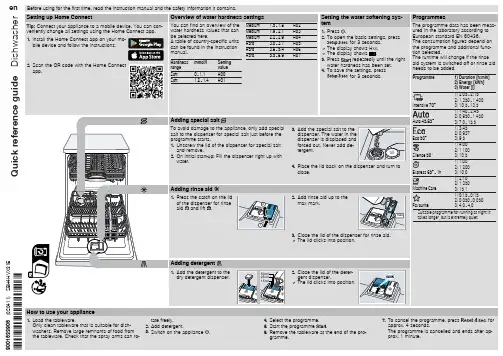

9013-0006 (03/11)INSTALLER: LEAVE THIS MANUAL WITH THE OWNERThe WELL-X1 tank comes with a 7 year warranty and the WELL-X1 digital control comes with a 2 year warranty. See back page for warranty informationIMPORTANT GENERAL SAFETY INFORMATION - ADDITIONAL SPECIFIC SAFETY ALERTS APPEAR IN THE FOLLOWING INSTRUCTIONS. READ CAREFULLY THE PRODUCT INSTALLATION, OPERATING AND MAINTENANCE MANUAL. FAILURE TO FOLLOW THE INSTRUCTIONS AND WARNINGS IN THE MANUAL MAY RESULT IN SERIOUS OR FATAL INJURY AND/OR PROPERTYDAMAGE, AND WILL VOID THE PRODUCT WARRANTY. THIS PRODUCT MUST BE INSTALLED BY A QUALIFIED PROFESSIONAL. FOLLOW ALL APPLICABLE LOCAL AND STATE CODES AND REGULATIONS, IN THE ABSENCE OF SUCH CODES, FOLLOW THE CURRENT EDITIONS OF THE NATIONAL PLUMBING CODE AND NATIONAL ELECTRIC CODE, AS APPLICABLE.This is the safety alert symbol. It is used to alert you to personal injury hazards. Obey all safety instructions that follow this symbol to reduce the risk of possible injury or death as well as property damage.1400 Division Road, West Warwick, RI 02893 T: 401.884.6300 F: 401.885.2567 1. TABLE OF CONTENTSGENERAL SAFETY INFORMATION ...........................................................2COMPONENTS ............................................................................................3INSTALLATION AND SIZING CONSIDERATIONS .....................................4INSTALLATION CONSIDERATIONS ..........................................................5PLUMBING ..................................................................................................6WIRING ........................................................................................................8STARTUP & ADJUSTMENT ........................................................................9PUMP PROTECTION & DIAGNOSTICS ...................................................13TROUBLESHOOTING ...............................................................................14REPLACEMENT PARTS ...........................................................................15This Product, like most Products under pressure, may over time corrode. weakenand burst or explode, causing serious or fatal injury, leaking or flooding and/or property damage. To minimize risk, a licensed professional must install and periodically inspect and service the Product. A drip pan connected to an adequate drain must be installed if leaking or flooding could cause property damage. Do not locate in an area where leakage of the tank or connections could cause property damage to the area adjacent to the appliance or to lowerfloors of the structure.Chlorine & Aggressive Water: The water quality can significantly influence the life ofthis Product. You should test for corrosive elements, acidity, total solids and other relevant contaminants, including chlorine and treat your water appropriately to insure satisfactory performance and prevent premature failure. NOTE: Inspect for shipping damage and notify freight carrier or store where purchased immediately if damage is present. To avoid risk of personal injury and property damage, if the product appears to be malfunctioning or shows signs of corrosion, call a qualified professional immediately. Current copies of the Product manual can be viewed at . Use proper safety equipment when installing.ELECTROCUTION AND EXPLOSION HAZARD! Before work is performed on the Product, turn off the power to theProduct and release all pressure in the system.As in all plumbing products and water storage vessels, bacteria can grow in this Product, especially during times of non-use. Consult yourlocal plumbing professional regarding any steps you mayplumbing system.DANGER! EXPLOSION HAZARD , WHENTHE WELL-X1®HAS BEEN IN SERVICEAND A CHANGE TO A HIGHER PRE-CHARGE PRESSURE IS NECESSARY DUE TO A REQUIRED CHANGE IN THE PRESSURE SWITCH SETTING, FAILURE TO FOLLOW INSTRUCTION MANUAL CAN CAUSE A RUPTURE OR EXPLOSION, POSSIBLY CAUSING SERIOUS OR FATAL INJURY , AND/OR PROPERTY DAMAGE. • DO NOT ADJUST THE PRE-CHARGE PRESSURE IF THERE HAS BEEN AREDUCTION OF THE PUMP CYCLE TIME OR THE PRE-CHARGE PRESSURE COMPARED TO ITS INITIAL SETTING. THIS IS BECAUSE REDUCTION IN PUMP CYCLE TIME CAN RESULT FROM LOSS OF TANK AIR PRESSURE WHICH IN TURN CAN MEAN THERE MAY BE INTERNAL CORROSION AND ANY RE-PRESSURIZATION OR ADDITIONAL PRESSURE COULD RESULT IN RUPTURE OR EXPLOSION, AND/OR PROPERTY DAMAGE.RELIEF VALVE REQUIRED . A relief valve has been installed which is set to open atexcessive pressures (100 psig or more). This will protect the Well-X1® and other system components should the pressure switch malfunction and fail to shut the pump off. The relief valve is installed at the connection of the Well-X1® to the system piping.Before attempting any service and disassembly, shut off power to the pump.Ensure power is disconnected prior to removing motor. Ensure power is disconnected before cleaning is attempted.This control is capable of running pumps to pressures that may exceed thelimitations of system components. Never set the operation pressure higher than that of the safe system capacity.This control can be adjusted to a narrow pressure differential. This can cause thepump to cycle rapidly with an improperly sized tank, leadingto pump damage. This may require a larger pressure tank than normally used.Every Well-X1® is air tested to 150 psig, the maximum working pressure for the Well-X1®.The pump controller is not a disconnect. The pump may be activated at any time.The electrical system must be considered energized at all times unless the circuit breaker is open. The disconnect for the controller must break all incoming power lines. As with a mechanical pressure switch, when installed with three wire 230 vac pumps or any 3-phase pump, a standard pump motor starter or a relay must be used.2. GENERAL SAFETY INFORMATION3. COMPONENTSThe Well-X1® combines all the standard well tank components in a single, easy to install package. The pressure tank, control and tank fittings are factory-installed. After removing from the carton, inspect the Well-X1 for damage and ensure all components are present.CONTROLPRESSURE TANKMOUNTING BRACKET4. INSTALLATION AND SIZING CONSIDERATIONSThe Well-X1® functions like a traditional pressure switch by cycling the pump on and off. The factory pressure settings are 40 psi cut-in and 60 psi cut-out. The controller allows these settings to be adjusted to best suit the application. The Well-X1® can operate in two primary modes:A. STANDARD OPERATIONUsing a standard 20 psi differential, the Well-X1® can be sized according to the chart below. In this application, the sizing and performance will be similar to a traditional pressure tank and mechanical switch combination.B. CONSTANT PRESSURE MODEThe Well-X1® control allows a narrow differential to provide consistent water pressure. The factory 20 psi differential can be reduced so the cut-in and cut-out pressures are within 10 psi. When installed as a constant pressure system, the chart below should be used to ensure the tank volume is sufficient to provide adequate cycle protection.A relief valve has been installed which is set to open at excessive pressures (100 psig or5. INSTALLATION CONSIDERATIONS LOCATIONThe Well-X1® is designed for indoor and outdoor installations. The NEMA 3 enclosure can be installed in direct weather. If installed outdoors, be sure the following conditions are met:• Do not install where ambient temperatures can drop below freezingor exceed 120° F.• Use water-tight: wiring conduit, wire nuts and conduit connectionsas dictated by applicable codes and ordinances.• Protect the piping from mechanical damage.• Install the relief valve blow down tube where venting water will notcause personal injury or damage the surrounding property.• Drip Pan and Drain: To avoid leaking and/or property damage,install with a drip pan connected to an adequate working drain keptclear at all times.ORIENTATIONEnsure the installation meets all applicable local codes and is installed by a qualified professional. Additionally, the following should be noted.• This unit is designed for vertical installation above ground only.Do not install horizontally or directly bury the unit. The Well-X1®may be installed below grade in a well pit or other suitableenclosure. Do not locate in an area where leaking or floodingcould cause property damage to surrounding areas.• Check codes to determine if there are any height requirementspertaining to the Well-X1®. Particularly, ensure the bottomdrain meets these requirements. If restrictions are imposed onthe proximity of drain connections to the floor, the unit may beelevated on blocks or the bottom drain tube can be removed andplugged, after which a sampling tap may be installed in the waterlines near the top of the Well-X1®.6. PLUMBING 1. Plumbing connections are similar to a traditional "tankcross" or "tank tee". Provisions are made for popular linesizes via a 1-1/4" NPT male outer thread and a 1" NPTfemale inner thread. The plumbing connections are notdirectional and allow flow from either side. When attachingvalves or fittings, uses the wrench flats provided.EXPLOSION HAZARD. Failure tofollow these instructions can cause a rupture or explosion possibly causing serious or fatal injury, flooding, and/or property damage.2. Install the supply piping from the well pump. If required, install a spring-loaded check valve.3. Install a shutoff (service) valve on the outgoing line. This will allow the Well-X1® to be tested prior to pressurizing the entire system. DO NOT place a shutoff on the incoming supply line.NOTE: The relief valve is sized for a maximum flow rate of 10 gpm at 125 psi. If the pump installation allows higherflow rates, an additional relief valve must be installed.4. Connect the water line from the well pump to the inlet of the Well-X1®.5. Plumb the outgoing supply to the building's water supply system or into the water treatment equipment (if present).6. Install a blow down tube from the relief valve to a drainor to within 6" of the floor as required by local codes.A drip pan connected to an adequate drain must be installed if leaking orflooding could cause property damage.7. WIRING 1. Shut off the circuit breaker for the well system. Loosenthe silver screw on top of the control and remove coverto expose the control wires.Electrocution hazard. For your safety, minimize the risk of electric shock, property damageor personal injury. Properly ground to conform with all governing codes and ordinances.2. The 12 gauge wire leads are pre-stripped and readyto accept standard wire nuts. Each wire is color codedto correspond with the diagram below. Use water tight conduit, connections, and wire nuts for an outside application.3. Wiring is similar to a traditional mechanical pressure switch. Two leads are connected to line supply, while the other supply the pump motor or starter. Wire the control to the line supply and pump motor or pump starter as required by the manufacturer's instructions. It is recommended that service switch be installed in addition to the circuit breaker. The disconnect for the controller must break all incoming power lines. This should interrupt line voltage and be installed near the Well-X1® and labeled appropriately.4. After completing the wiring, reattach top cover and tighten screw. Ensure no loose wires protrude from the control.L LMOTOMOTOBLACKWHITE/STRIPEBLUEWHITESCREW8. STARTUP & ADJUSTMENT1. After plumbing and wiring are complete, close the service valve to allow startup without pressurizing the entire plumbing system. If a service valve was not installed, close all fixtures in the home. Ensure the bottom drain is closed.2. Restore power to the Well-X1® by turning on the breaker and electrical service switch (if installed). The display will illuminate.3. The display will read "88" to test the display illumination, then a number identifying the control type (i.e. 15). This number is for factory use and may vary by model and manufacture date.4. After a slight pause, the pump will start and the system pressure will be displayed. This number will increase as the pump runs and the tank fills.Note: Some jet pumps may be difficult to prime, resulting in the low water cut-off activating if pressure will not build above 10 psig. Depressing the s arrow will temporarily override the low water cut-off to allowproper priming.8. STARTUP & ADJUSTMENT (con't)5.The factory cut-out (pump off) setting is 60 psig. When the pump reaches 60 psig, the Well-X1® will shut the pump off. Check the plumbing for leaks and repair before continuing. If during startup the cut-out setting of 60 psig cannot be reached, read the adjustment instructions to lower the cut-out within the pump's capability.6. Slowly open the service valve to allow the system to pressurize. The pressure may drop slightly during this process. After the valve is fully open, open the fixture closest to the Well-X1® to begin drawing water from the tank.7. When the system reaches the factory cut-in (pump on) setting of 40 psig, the pump will start. Like a traditional mechanical switch, the pressure will begin to rise, repeating the cycle. If desired, the Well-X1® settingscan now be adjusted as shown below.1. To enter the programming mode, press and hold the ■ button until LO appears. This is the cut-in setting. Factory default will be 40 psi.2. Use the s and t arrows to raise or lower the cut-in setting. Adjustment can be made within 10 psig or as wide as 55 psig of the cut-out setting to 60 psig. If this range is exceeded, the display will cease to change even though the button is being pressed. Minimum setting is 10 psig.PRESSURE ADJUSTMENTThe Well-X1® utilizes a simple cut-in/cut-out adjustment. Before setting the desired operating range, refer to the chart below to ensure the Well-X1's Maximum Acceptance is not exceeded. Adjust the precharge as shown on page 12.CAUTION!Exceeding Maximum Acceptance will reduce tank life and cause irreparable damage.Step 1: Find the Maximum Acceptance for the installed Well-X1® model.Step 2: Ensure the desired operating range does notexceed that model's Maximum Acceptance.3. To adjust the cut-out, depress ■ once and the display will read HI . Again, press the t or s buttons to raise or lower the setting. The same 10-55 psig differential range applies.Maximum setting is 80 psig.4. A fter adjusting the cut-in and cut-out, release the buttons. After a slight pause, Pr will be displayed, indicating the settings are saved in the event of a power outage.PRECHARGE ADJUSTMENTWhenever the cut-in (LO) setting is changed, the tank precharge must be adjusted. To do this, shut the Well-X1® off and open the drain to empty all water. Using an air gauge, adjust the precharge to 2 psig below the cut-in (LO) setting.Failure to adjust the precharge will result in tank damageor water interruption.DANGER! Explosion Hazard. If theWell-X1®has been in service and a change to a higher pre-charge is necessary due to a required change in the setting, failure to follow instruction below can cause a rupture or explosion, possibly causing serious or fatal personal injury, and/or property damage.• Do not adjust or add pressure if there has been a loss of air.• Do not adjust the pre-charge pressure if there is visible exterior corrosion.• Do not adjust the pre-charge pressure if there has been a reduction in pump cycle time or the pre-charge pressure compared to its initial setting. This is because reduction in pump cycle time can result from loss of tank air pressure which in turn can mean there may be internal corrosion and any re-pressurization or additional pressure could result in rupture or explosion.9. PUMP PROTECTION AND DIAGNOSTICSThe Well-X1® continually monitors pressure, cycle time and voltage to protect the well pump. The following error codes alert the user to a potential problem, prompting service.E1: Rapid CycleE2: Low Suction (low water cut-off)E3: Voltage ProtectionWELL-X1® ERROR CODESWhen an error occurs, the display will flash a diagnostic code.10. TROUBLESHOOTING11. REPLACEMENT PARTS328AMTROL, AMTROL logo, GUARDIAN CP and Well-X1 are registered trademarks of AMTROL Inc. and affiliatesin the U.S. and elsewhere. All rights reserved.Revised 01/111400 Division Road, West Warwick, RI 02893 T: 401.884.6300 F: 401.885.2567 。
L8对讲系统使用说明书第1节产品型号说明序号产品型号产品名称外观尺寸mm 安装尺寸mm1 L8-5002 L8非可视主机2 L8-5002M L8黑白可视主机3 L8-5002L L8非可视联网主机4 L8-5002GL L8非可视联网刷卡主机5 L8-5002ML L8黑白可视联网主机6 L8-5002MGL L8黑白可视联网刷卡主机7 L8-5002MLC L8彩色可视联网主机8 L8-5002MGLC L8彩色可视联网刷卡主机9 L8-5002LF L8非可视联网副主机10 L8-5002GLF L8非可视联网刷卡副主机11 L8-5002MLF L8黑白可视联网副主机12 L8-5002MGLF L8黑白可视联网刷卡副主机13 L8-5002MLFC L8彩色可视联网副主机14 L8-5002MGLFC L8彩色可视联网刷卡副主机15 L8-5002MLW L8黑白可视围墙主机16 L8-5002LW L8非可视围墙主机17 L8-5002GLW L8非可视围墙刷卡主机18 L8-5002MGLW L8黑白可视围墙刷卡主机19 L8-5002MLWC L8彩色可视围墙主机20 L8-5002MGLWC L8彩色可视围墙刷卡主机2型:140×342×70mm4型:120×373×51 mm10型:170×386×54mm11型:380×240×54mm(1)2型预埋盒:134×340×50 mm铁门安装:130×300×40mm(2)4型预埋盒:344×106×45(52) mm铁门安装:105×340×32mm(3)10型预埋盒:142×358×64mm铁门安装:140×332×48mm(4)11型预埋盒:352×213×64mm铁门安装:322×210×48mm注:型号后面带“T”为触控主机第2节 产品介绍2.1外观摄像头喇叭显示屏电源指示麦克风读卡部操作键盘安装螺丝盖板2.2功能特点(1)可选择不同外观的液晶显示和数码显示;(2)操作键盘可采用机械按键或电容触控按键操作; (3)CCD 摄像头角度可调,带夜间可视;(4)可与管理中心进行语音、视频、数据联网通信; (5)可与分机实现双向呼叫对讲开锁功能,(6)音频采用半双工和全双工混合对讲方式,具有声音不丢失,且声音大,不嘯叫; (7)系统采用网络线传输语音、视频、数据通信; (8)采用FLASH 存储用户资料,永不丢失;(9)一户一密码,具有密码开锁和防区密码撤防功能;(10)可内置或外配IC/ID 门禁,具有刷卡开锁和防区布撤防功能; (11)具有开门检测、电梯控制等功能;(12)联网功能强大,可接入TCP/IP 网络; (13)可预埋式安装、嵌入式安装。
应用CerabarM系列压力变送器可以测量气体、蒸气和液体的表压和绝压,适用于各个领域的过程控制。
模块化的结构设计使其使用更加灵活方便。
技术资料TI321P/28/zh智能型压力变送器cerabarMPMC41,PMC45cerabarMPMP41,PMP45采用陶瓷或扩散硅传感器,抗过载能力强可选:模拟型,智能型或PROFIBUS-PA电子模块特性和优点·精度·传感器—干式电容陶瓷传感器压力可·电子部件外壳过程连接—线性度优于设定量程的0.2%—量程范围可调,TD10:1—长期稳定性优于0.1%达40bar(600psi)—抗过载能力强、密封性能好、能用于真空场合,抗腐蚀,耐磨损—扩散硅式金属膜片传感器压力可达400bar(6000psi)—模拟式:经济型,响应速度快,尤其适用于快速反应过程。
—智能式:通过HART协议实现多种操作程序。
·不锈钢外壳,能满足食品及制药工业的特殊卫生要求。
环氧树脂涂层铝外壳符合过程工业的要求。
·螺纹连接,卫生型连接,法兰连接—PROFIBUS-PA:数字通信PMC41G1/2APMC45DIN11851PMP45Miniclamp仪表型号PMC41带G/螺纹12PMC41带/NPT螺纹12PMC45卫生型螺纹PMC45法兰式PMC45·齐平式陶瓷传感器,()。
·测量范围:表压或绝压:10mbar...40bar(0.15psi...60psi)·过程连接:—螺纹连接—卫生型连接—法兰连接·过程温度:-40...+125℃(-40...+257°F)150℃(302可持续max.1小时·不锈钢(1.4404/AISI316L)或铝外壳·3A认证和EHEDG认证采用高净度99.9%陶瓷,适用于易磨损和粘性介质,陶瓷材料经FDA认证,适用于卫生型场合++°F)PMC41·陶瓷传感器·测量范围:表压或绝压:10mbar...40bar(0.15psi...600psi)·过程连接:标准型,所有普通的压力表连接·过程温度:-40...+100℃(-40...+212°F)·不锈钢(1.4404/AISI316L)或铝外壳,适用于各种工程应用领域中的压力测量PMP41内螺纹适配器PMP41齐平式薄膜PMP45DIN11851,DN25PMP45小型卡口PMP41·扩散硅金属膜片传感器,适用于各种工程应用领域中的压力测量·测量范围:表压或绝压:100mbar...400bar(1.5psi...6000psi)·过程连接—齐平式膜片,G1/2外螺纹—内螺纹连接头(DIN3852-E-G1/2)和其他螺纹型式可选—连接头可更换:采用密封圈或气密焊接方式连接·过程温度:-40...+100℃(-40...+212°F)·不锈钢(1.4404/AISI316L)或铝外壳PMP45·齐平式金属膜片传感器,适用于卫生型应用·测量范围:表压或绝压:100mbar...400bar(1.5psi...6000psi)·过程连接:—卫生型—螺纹型·过程温度:-40...+125℃(-40...+257°F)+15(30,小时·不锈钢或铝外壳·认证0+2°F)max.1(1.4404/AISI316L)3A外壳电子插件CerabarM外壳为不锈钢材料,抗化学腐蚀,采用卫生型设计,便于清洗--无死区,抗冷凝,适用于食品和制药行业。
MYZxA微型针式打印机使用说明书V1.02蚂蚁(东莞)科技发展有限公司MYZXA使用说明书目录目录 (i)一.特征与性能指标 (3)1.1主要特征 (3)1.2 性能指标 (3)1.3 型号说明 (5)二.安装说明 (5)2.1 打印机外形 (5)2.2 外观尺寸 (6)三.操作说明 (6)3.1 接口说明 (6)3.1.1 电源接口 (6)3.1.2 串行接口一 (7)3.1.3 串行接口二 (8)3.1.4 并行接口 (9)3.2 指示灯说明 (10)3.3按键操作说明 (10)3.3.1 走纸 (10)3.3.2 打印自检 (10)3.3.3 参数设置 (10)四.打印命令 (11)4.1 纸进给命令 (11)4.1.1 打印并换行 (11)4.1.2 打印并进纸 (11)4.1.3 设置行间距 (11)4.1.4 设置字间距 (11)4.1.5 换页 (12)4.2 选择字符集命令 (12)4.2.1 选择字符集1 (12)4.2.2 选择字符集2 (12)4.2.3 选择汉字打印 (12)4.3 格式设置命令 (12)4.3.1 设置页长 (12)4.3.2 设置装订长 (13)4.3.3 设置装订长 (13)4.3.4 设置垂直造表值 (13)4.3.5 执行垂直造表 (13)4.3.6 设置水平造表值 (13)4.3.7 执行水平造表 (14)4.3.8 打印空格或空行 (14)4.3.9 设置左限 (14)4.3.10 设置右限 (14)4.4 字符设置命令 (14)4.4.1 横向放大 (14)4.4.2 纵向放大 (15)MYZXA使用说明书4.4.3 横纵向放大 (15)4.4.4 字符放大一倍 (15)4.4.5 横纵向放大不同倍数 (15)4.4.6 允许/禁止上划线 (15)4.4.7 允许/禁止下划线 (15)4.4.8 选择上下标 (16)4.4.9 设置错位打印 (16)4.4.10 取消错位打印 (16)4.4.11 允许/禁止反白打印 (16)4.4.12 设置/取消反向打印 (16)4.4.13 设置纵向打印 (16)4.4.14 设置横向打印 (17)4.4.15 字符旋转打印 (17)4.4.16 设置打印方向 (17)4.5 图形打印命令 (17)4.5.1 打印点阵图形 (17)4.5.2 打印曲线 (18)4.5.3 打印条形码 (18)4.6 初始化命令 (18)4.6.1 打印机初始化 (18)4.7 数据控制命令 (18)4.7.1 回车 (18)4.7.2 允许/禁止打印 (19)五.使用与维护 (19)5.1 产品维护 (19)5.2.1 打印机使用注意事项 (19)5.2.2 打印机故障分析及排除 (19)附录西文字符集1 (20)附录西文字符集2 (21)版本说明 (21)MYZXA使用说明书一.特征与性能指标1.1主要特征◎采用针式打印方式◎采用高性能进口机芯◎集机芯与控制板于一体的独立打印模块◎体积小、外型美观、便于安装、功能完备、操作简单等特点◎自带单片机处理,具有标准的串行接口(RS232/485/TTL)接口、并口◎支持汉字、字符、图形等实时打印命令◎指令集与传统打印机兼容◎支持低功率模式打印◎广泛适用于医用器材、消防控制、工业控制、各种仪器仪表等需要打印的行业1.2 性能指标MYZXA使用说明书1.3 型号说明二.安装说明2.1 打印机外形说明:1、LF键/状态指示灯4、纸仓/纸卷2、纸仓开关5、固定架3、打印机头6、色带2.2 外观尺寸尺寸说明:外形尺寸:长X宽X高= 107.4 X 61.4 X 66.8 mm开孔尺寸:长X 宽= 102.4+0.5 mm X 56.4+0.5 mm嵌入深度:58.8 mm三.操作说明3.1 接口说明3.1.1 电源接口MYZXA打印机支持两种供电方式:1、5V /15W直流电源;2、9~24V/30W 直流电源。