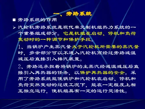
旁路功能介绍
- 格式:doc
- 大小:31.50 KB
- 文档页数:3

汽轮机旁路系统的功能及其选择岗位职责摘要:汽轮机旁路是单元制大型火力发电厂的重要辅助系统,旁路系统设计直接关系到机组的运行方式和控制策略。
发达国家中,大型机组担当调峰任务很重,旁路系统带来的好处相当明显。
在我国,大容量再热式机组都采用单元制系统,为了便于机组启停、调峰、事故处理和适应特殊运行方式,绝大多数再热式机组也都设置了旁路系统。
但事实上,不同型式的汽轮机,其旁路系统的容量和功能应不尽相同。
汽轮机旁路系统;功能与作用;功能选择一、汽轮机旁路的功能与作用考虑到汽轮机的空载流量与锅炉的最低负荷不一致,以及低负荷时中间再热器的保护问题,中间再热式机组应设置旁路系统,每一级旁路中都装有减温减压器。
当汽轮机的负荷低于锅炉稳定燃烧的最低负荷时,锅炉多送出的蒸汽可经过降压减温后送入再热器或低参数的蒸汽管道或直接排入凝汽器以回收工质。
当汽轮机负荷很低而使流经锅炉再热器的蒸汽量不足以冷却锅炉再热器时,绕过高压缸且经过旁路系统减温减压器冷却的蒸汽,可进入锅炉再热器进行冷却,从而保护再热器。
1、缩短机组启动时间及汽机冲转过程中协调蒸汽参数和流量汽轮机滑参数热态启动时,蒸汽进入气缸与气缸内壁接触,蒸汽温度上升较快,由于汽缸壁较厚且高中压缸为多层缸缸结构,传热到外壁需经较长时间,汽缸内、外壁容易出现较大的温差。
当汽机滑参数冷态启动时,汽缸壁温较低,而锅炉来的过热蒸汽温度很高,导致主蒸汽温度与气缸和转子温度不协调,容易引起汽轮机汽缸及其他部件热应力过大,缩短机组使用寿命。
故在机组启动期间,除监视汽缸内、外壁温差外,还必须控制好金属温度的升降速度。
一般来讲,单元机组在启动过程中,锅炉蒸汽温度与汽机汽缸金属温度不协调是由锅炉的特性决定,先以低参数蒸汽冲转汽轮机,之后随着汽轮机升速、并网、带负荷的要求,不断提高主蒸汽的参数和流量。
所以机组启动时间的长短取决于锅炉达到汽轮机冲转要求的蒸汽参数(包括主蒸汽和再热蒸汽)的时间,而锅炉升温、升压速度取决于锅炉疏水管的排放。

旁路系统及操作说明书新华控制工程有限公司XIN HUA CONTROL ENGINEERING CO,.LTD中国上海SHANGHAI . CHINA目录一、汽轮机旁路系统简介二、汽轮机旁路系统功能三、旁路控制系统及其组成四、旁路运行方式五、旁路的保护与联锁六、旁路系统操作简介附图1.BPC-I旁路调节系统图2.BPC-I控制柜装配图3.旁路通讯电缆连接图4.旁路启动曲线汽轮机旁路系统简介汽轮机旁路系统是与汽轮机并联的蒸汽减温减压系统。
它由蒸汽旁路阀门、旁路阀门控制系统、EH执行机构和旁路蒸汽管道组成。
其作用是将锅炉产生的蒸汽不经过汽轮机而引到下一级压力和温度的蒸汽管道或冷凝器。
蒸汽旁路系统有两种:一种是将锅炉产生的蒸汽直接引入冷凝器,这种旁路系统称为大旁路。
另一种是由高、低压两级旁路系统组成:旁路汽轮机的高压缸而将蒸汽从锅炉引入再热器的称为高压旁路;旁路汽轮机的中、低压缸而将蒸汽从再热器出口引入冷凝器的称为低压旁路。
大型火电机组都采用高参数、中间再热式的热力系统,采用一机一炉的单元配置。
在这种机组中,一台锅炉只向一台汽轮机供汽,这就要求锅炉的产汽量与汽轮机的耗汽量保持平衡。
而实际上汽轮机的空载流量仅为汽轮机额定蒸汽流量的5%~8%,远远小于锅炉的最低蒸发量(30%~50%)。
锅炉在更低的燃烧率下不能稳定运行。
因此必须有其它的蒸汽管道,作为锅炉的负载,承担其余的蒸汽流量。
另外当事故工况下汽轮机甩去负荷或停机时,大量的多余蒸汽必须通过旁路阀门而排入冷凝器,减少锅炉安全门起跳,同时避免大量蒸汽排入大气。
因此在中间再热机组中配置蒸汽旁路系统可以改善锅炉和汽轮机特性上的差异,提高机组的安全性和经济性。
北重330MW机组一般都采用70%BMCR容量的高压、2×65%BMCR低压两级串联旁路系统。
对于北重中压缸启动机组来说,旁路控制系统的作用更显得突出,旁路控制品质的好坏直接关系到机组的正常运行。
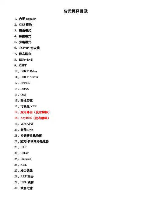
名词解释目录1、内置Bypass/2、OBS模块3、路由模式4、桥接模式5、旁路模式6、TCP/IP 协议簇7、静态路由8、RIP(v1/v2)9、OSPF10、DHCP Relay11、DHCP Server12、PPPoE13、DDNS14、QoS15、弹性带宽16、可视化VPN17、应用路由(没有解释)18、AnyDNS(没有解释)19、Web认证20、智能DNS21、多链路负载均衡22、MIPS多核网络处理器23、PAP24、CHAP25、Firewall26、ACL27、端口镜像28、ARP攻击29、URL跳转30、域名过滤1、内置Bypass/名词解释:旁路功能详细解释:网络安全设备一般都是应用在两个或更多的网络之间,比如内网和外网之间,网络安全设备内的应用程序会对通过他的网络封包来进行分析,以判断是否有威胁存在,处理完后再按照一定的路由规则将封包转发出去,而如果这台网络安全设备出现了故障,比如断电或死机后,那连接这台设备上所有网段也就彼此失去联系了,这个时候如果要求各个网络彼此还需要处于连通状态,那么就必须Bypass出面了。
Bypass顾名思义,就是旁路功能,也就是说可以通过特定的触发状态(断电或死机)让两个网络不通过网络安全设备的系统,而直接物理上导通,所以有了Bypass后,当网络安全设备故障以后,还可以让连接在这台设备上的网络相互导通,当然这个时候这台网络设备也就不会再对网络中的封包做处理了。
软件测试过程中出现bypass code,测试未完全开发的软件时,有些功能还未完成,会产生error,通过bypass code,可以忽略及跳过这些error,从而继续替他功能的测试.2、OBS模块名词解释:光突发交换网络详细解释:光突发交换中的“突发”可以看成是由一些较小的具有相同出口边缘节点地址和相同QoS要求的数据分组组成的超长数据分组,这些数据分组可以来自于传统IP网中的IP包。
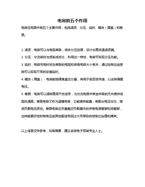
电容的五个作用
电容在电路中有五个主要作用,包括滤波、分压、延时、耦合(隔直)和旁路。
1. 滤波:电容可以与电阻串联,结合分压定律,设计出高低通滤波器。
2. 分压:交流容抗与频率成反比,利用这一特性,电容可实现分压功能。
3. 延时:电容充电时间与串联的电阻和自身电容大小有关,通过控制这些参数可以实现不同的定值延时。
4. 耦合(隔直):电容能够隔离直流分量,常用于前后级传递,以去除偏置电压。
5. 旁路:电容可以滤除高频干扰信号,为交流电路中某些并联的元件提供低阻抗通路。
旁路电容又称为退耦电容,它能提供能量,使输出电压均匀,降低负载电压波动。
旁路电容应尽量靠近负载器件的供电电源管脚和地管脚,这样能更好地抑制电压或其他输信号因过大而导致的地电位抬高和噪声。
以上信息仅供参考,如有需要,建议咨询电子领域专业人士。
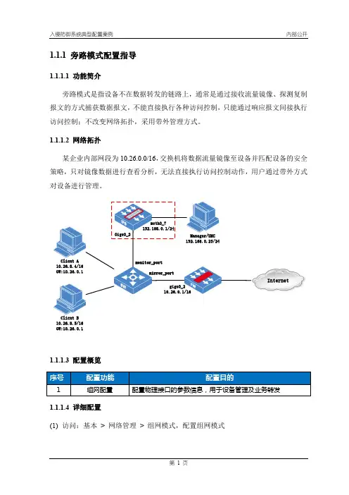
1.1.1 旁路模式配置指导1.1.1.1 功能简介旁路模式是指设备不在数据转发的链路上,通常是通过接收流量镜像、探测复制报文的方式捕获数据报文,不能直接执行各种访问控制,只能通过响应报文间接执行访问控制;不改变网络拓扑,采用带外管理方式。
1.1.1.2 网络拓扑某企业内部网段为10.26.0.0/16,交换机将数据流量镜像至设备并匹配设备的安全策略,只对镜像数据进行查看分析,无法直接执行访问控制动作,用户通过带外方式对设备进行管理。
InternetClient B10.26.8.5/16GW:10.26.0.11.1.1.3 配置概览(1)访问:基本> 网络管理> 组网模式,配置组网模式说明:1、配置旁路模式后,该接口组中的两个接口可独立使用;2、旁路模式下,接口管理状态与“启动接口状态同步”功能无关。
1.1.1.5 功能验证管理员(192.168.0.25)可通过带外地址192.168.0.1对设备进行管理。
业务接口可查看到镜像流量数据(RX方向)。
1.1.1.6 常见问题----------------------------------------------【常见问题1】----------------------------------------------旁路接口收到镜像报文并匹配策略后,则丢弃该流量;设备支持断电保护功能,则在重启、断电情况下,接口组中的两个接口互通;如有两条镜像流量分别连接设备一组接口中,当设备正常运行时,gige0_2和gige0_3口匹配策略后直接丢弃数据;当设备断电时,将自动触发断电保护功能,即gige0_2和gige0_3口互通,产生环路。
解决方案:1、交换机进行VLAN隔离;2、设备使用不同接口组的旁路接口。
----------------------------------------------【常见问题2】---------------------------------------------- 以迪普交换机为例,配置端口镜像:。

旁路系统功能介绍苏尔寿的旁路系统是一个满足整个电厂操作要求(锅炉和汽机)的相对独立的系统。
旁路系统和其他系统之间信号数量是较少的。
更重要的是,一个旁路控制器可以精确满足旁路操作的要求,并可以简便地实现安全功能或其他快开或速闭功能。
一、对于高压旁路来说主要有以下几个功能:1.锅炉启动控制器依据锅炉蒸汽产量的需要控制和增加锅炉蒸汽压力。
旁路控制蒸汽到再热器中,从而确保过热器和再热器中有适当的蒸汽流量。
只要有蒸汽通过旁路装置,旁路控制器必须控制进入再热器的蒸汽温度。
2.汽机启动HP旁路控制器必须控制蒸汽压力,直至锅炉主控制器可以进行压力控制为止。
3.负荷操作在汽机带负荷以后,旁路处于关闭状态,但是控制器可以防止超压和压力上升速率过快。
4.汽机甩负荷/跳闸旁路打开,必要时借助快开装置进行,以防止过高的蒸汽压力并且控制压力。
直到汽轮机再次承担起负荷为止。
5.安全功能(将旁路作为安全阀,本机组没有配备安全功能)下面就各个功能做一个简单的介绍。
自动启动过程和运行状态:旁路的自动启动过程是从锅炉点火到汽机接收所有蒸汽。
高压旁路自动启动有以下几个过程:最小阀位-最小压力-设定阀位-冲转压力。
在冷态启动时,也就是主汽压力小于1.0MPa的时候,旁路自动启动的过程如下:在锅炉点火以后,在触摸屏上点击STARTUP按钮,这时候旁路系统的状态显示会出现Ymin on和cold start,这时候进入最小阀位过程,高旁阀门会开启到设定的最小阀位Ymin,它可以确保在点火后过热器和再热器中有一定蒸汽流量通过。
这时候高旁会保持这个阀位不动。
随着燃烧主蒸汽压力上升,当有足够蒸汽使得汽压力上升到设定的最小压力Pmin的时候,进入了最小压力控制过程,屏幕显示切换到Warm start状态,这时候旁路会维持主汽压力为Pmin,在跟随燃烧蒸汽流量增加的情况下,为了维持此压力高旁阀门会打开控制压力。
在阀门开度达到设定的阀位Ym(由锅炉启动过程中需要的蒸汽流量决定)的时候,进入设定阀位过程。
汽机旁路知识介绍根据自己学习总结介绍了,汽机旁路系统的配置、用途、功能及控制与保护。
列举了执行机构(气、液、电动)品牌厂家和其余汽机旁路的生产厂家。
并对汽机旁路亚临界、超临界和超超临界机组材料的选用;Cv值的计算;旁路喷水调节阀流量的确定;管道流速的选择与口径的确定等问题进行了分析。
对喷嘴等关键部件进行了思考。
一、汽轮机旁路概述汽轮机旁路系统是与汽轮机并联的蒸汽减温减压系统。
它由蒸汽旁路阀门、旁路阀门控制系统、执行机构和旁路蒸汽管道组成。
其作用是将锅炉产生的蒸汽不经过汽轮机而引到下一级压力和温度的蒸汽管道或冷凝器。
蒸汽旁路系统有两种:一种是将锅炉产生的蒸汽直接引入冷凝器,这种旁路系统称为大旁路。
另一种是由高、低压两级旁路系统组成:旁路汽轮机的高压缸而将蒸汽从锅炉引入再热器的称为高压旁路;旁路汽轮机的中、低压缸而将蒸汽从再热器出口引入冷凝器的称为低压旁路。
大型火电机组都采用高参数、中间再热式的热力系统,采用一机一炉的单元配置。
在这种机组中,一台锅炉只向一台汽轮机供汽,这就要求锅炉的产汽量与汽轮机的耗汽量保持平衡。
而实际上汽轮机的空载流量仅为汽轮机额定蒸汽流量的2%~5%,远远小于锅炉的最低稳定燃烧蒸发量(30%~50%)。
锅炉在更低的燃烧率下不能稳定运行。
因此必须有其它的蒸汽管道,作为锅炉的负载,承担其余的蒸汽流量。
另外当事故工况下汽轮机甩去负荷或停机时,大量的多余蒸汽必须通过旁路阀门而排入冷凝器,减少锅炉安全门起跳,同时避免大量蒸汽排入大气。
因此在中间再热机组中配置蒸汽旁路系统可以改善锅炉和汽轮机特性上的差异,提高机组的安全性和经济性。
汽机旁路系统首先用于欧洲的直流炉中,几乎所有的欧洲国家均使用了高低压汽机旁路系统,包括汽包炉.高压旁路把来自锅炉过热器的蒸汽排到再热器,低压旁路把来自再热器的蒸汽排到凝汽器,欧洲国家的旁路通常为100%的容量,中国的系统主要容量多选用在40%MCR,并且具有安全保护功能.为了满足大型汽轮机组启动运行和安全的需要,给机组配置旁路装置和切实可行的控制系统是十分必要的,旁路系统主要有电动和液动两大流派,气动系统主要应用于中小型机组. 旁路系统装置是火电机组重要的辅助设备,旁路系统设备的可靠性对电厂安全和经济运行影响较大,而系统设备的设计、安装、调试对旁路的运行效果有很大的影响。
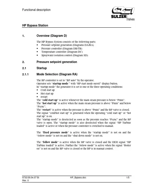
HP Bypass Station1. Overview (Diagram D)The HP Bypass System consists of the following parts:•Pressure setpoint generation (Diagrams DA/RA)•Pressure controller (Diagram DB/TB)•Temperature controller (Diagram DC)•Spraywater isolation control (Diagram SD)2. Pressure setpoint generation2.1 Startup2.1.1 Mode Selection (Diagram RA)The BP controller is set to “BP auto” by the operator.Operator sets “startup mode ” with “BP start mode on/off” display button.In “startup mode” the generator it is set to one of the three operating conditions:•Cold start up•Hot start up•restartThe “cold start up” is active whenever the main steam pressure is below “Pmin”.The “hot start up” is active when the main steam pressure is above “Pmin” and below“Psync”.The “restart” is active when the pressure is above “Pmin” and the BP valve is closed.The signal “cold/hot start up” is generated when the operating “cold start up” or “hotstart up” is on.The “startup mode” is deselected as soon as the pressure reaches “Psync” and the BPvalve is open. The “startup mode” is also deselected when the signal “HP Turbineloaded” is active or when the pressure controller is switched to manual.The “fixed pressure mode” is active when the “startup mode” is not on and the“follow mode“ is not on and the “shut down mode” is not on.The “follow mode” is active when the BP valve is closed and the DEH signal “HPTurbine loaded” is active. Further the “follow mode” is active when the signal “Boileron” is not on and the BP valve is closed or the BP is in manual control.2.1.2 Setpoint Generator (Diagram DA)At “startup mode ” with no pressure in the boiler the setpoint generator is in the “cold start up ” condition. The pressure setpoint “Ps actual” is set to “Pmin” value. And the BP valve opens to a minimum position value “Ymin” (see 3. Pressure Controller).As soon as the main steam pressure is above “Pmin” the “hot start up ” condition is activated. The pressure setpoint “Ps demand” is increased, whenever the BP valve position “Yset” exceed the position value “Ym”. The increase of the pressure set point is limited by the gradient limiter and only positive pressure gradient is allowed during “hot start up” operation, decrease of the pressure setpoint “Ps actual” is not permitted in this operation mode.As soon as the main steam pressure reaches “Psync” the “startup mode” is deselected and the “fixed pressure mode ” is activated. The pressure setpoint “Ps demand” is set at the current last pressure set point “Ps actual”. In “fixed pressure mode” the pressure set point can be adjusted by the operator.With increasing turbine load BP valve will close automatically due to pressure drop. As soon the BP valve is closed the set point generator will switch over to “follow mode ” (see: 2.2 Load Operation). In this mode pressure set point “Ps actual” will follow main steam pressure.In case of pressurized boiler at startup the “restart ” condition is selected while the BP valve is closed. The pressure set point “Ps actual” is following the main steam pressure but only negative pressure gradients are allowed. As soon as the boiler pressure starts to increase the bypass valve will start to open. When the BP valve open the setpoint generator will go to “hot start up ” condition if the pressure is still below “Psync” or to “fixed pressure mode ” if the pressure at startup is already above “Psync”.T im eB P v P re s s u re / L o a d / F lo w 100 %50 %20 %40 %60 %100 %80 %2.2 Load Operation (Diagram /DA/RA)During load operation, i.e. when the HP turbine is taking over all the produced steam,the bypass valves are closed. The “follow mode” is activated.The pressure set point “Ps actual” is following the actual main steam pressure. Themaximum pressure gradient is limited, depending on the actual main steam pressure. Adifferential pressure value “dP” is added to the pressure set point “Ps actual” to keepthe BP valve closed (see: 3. Pressure Controller).If the main steam pressure is increasing above the Bypass controller set point “Psactual + dP” the BP valve starts to open. The set point generator is switched over to“fixed Pressure mode”.2.3 Shut down2.3.1 Mode selection (Diagram RA)When a plant shut down is planned the “Shut down mode” can be selected by theoperator. The “Shut down mode” can only be selected when the DEH signal “HPTurbine loaded” is active and the BP controller is on auto. As soon as the DEH signal“HP Turbine loaded” is deactivated the “Shut down mode” is deselected and the setpoint generator change to “fixed pressure mode”.When the boiler shuts down, the BP valve will close and the set point generator isswitched to “follow mode”2.3.2 Setpoint Generator (Diagram DA)At “Shut down mode ” the pressure set point “Ps actual” is following the main steam pressure but only negative gradients are allowed. As soon as the boiler pressure starts to increase the BP valve start to open.After the “Shut down mode” is deselected the set point generator is on “fixed pressure mode ”. At “fixed pressure mode” the set point generator controls the actual pressure. As soon the boiler shuts down the BP valve is closing and the pressure generator is switched to “follow mode ”. In “follow mode” the pressure set point will again follow the actual main steam pressure.3. Pressure Controller (Diagram DB)The pressure controller is receiving the actual main steam pressure signal and the pressure set point “Ps actual” from the set point generator. The controller is generating the common valve position demand signal. The signal is send to four M/A station where the valves can also be operated individually.In “follow mode ” when the “dP on” is active a differential pressure is added to the pressure setpoint “Ps actual” to keep BP valve close.At “startup mode ” when the “cold start up ” condition is active the BP valve are opened to a minimum position “Ymin”. The “Ymin on“ is deselected when position is above the minimum position “Ymin”.B P v P re s s u re / L o a d / F lo w 100 %50 %20 %40 %60 %100 %80 %4. Fast open and trip close logic (Diagram TB)The “monitor trip” command for fast opening of the BP valves is generated from DEHsignals “Turbine trip” or when the main steam pressure has reached the quick openingpressure threshold “dp max” above the pressure setpoint “Ps actual”.The “monitor trip” is blocked when pressure is below the pressure value “Pfo” andduring the “startup sequence” is active.The HP bypass valve will emergency close in case of low spray water pressure or toohigh HP-BP outlet temperature.5. Temperature controller (Diagram DC)The temperature controller is receiving the actual signal “HP-BP outlet temperature”from the transmitters and the “Temp setpoint“ set by the operator. The controller isgenerating the spray water valve position demand signal.The feed forward signal is generated from “Main steam pressure” and BP valveposition and is added to the valve position demand signal. With the adjustable value“wpl” the feed forward signal can be adapted.The temperature controller has one M/A station to control the BPE spray valve.The temperature controller is set to automatic mode as soon the BP valve is opened.When the BP valve closes the spray water valve closes also, and the temperaturecontroller is set to manual.The steam flow is calculated out of the BP valve position, main steam pressure andtemperature.7. Spray water isolation valve control (Diagram SD)The spray water isolation valve is open as soon the BP valve is not closed. When theBP valve is closed the spray water isolation valve will close again.IP Bypass station1. Overview (Diagram /D)The IP-Bypass Controller consists of the following partsPressure set point generation (Diagrams /DE/RE)Pressure controller (Diagram /DF)Quick open and emergency close functions (Diagram TF)Temperature controller (Diagram /DG)Spray water block valve (Diagram /SH)2. Pressure set point generation (Diagrams /DE and /RE)2.1 Boiler start up2.1.1 Valve closedBoiler and steam production is started. IP-Bypass is kept closed until pressure reachesPmin.Automation:IP-Bypass A/M station set to auto by the operatorThe “startup mode” is set by operator with “Start up on/off” signal.The valve is kept closed until hot reheater pressure reaches Pmin2.1.2 Min pressureAs steam production increases, LP-Bypass is opening and controlling pressure at Pminset point. When valve opening reaches Ym value pressure set point will be increasedby the predefined gradient.Automation:The A/M stations are auto, the “startup mode” is set.The valve will open to keep pressure constant.When valve opening reaches Ym the operation mode change to pressure ramp2.1.3 Pressure rampAs steam production increase, the pressure increase according defined gradient. Thepressure is increased up to final startup pressure Psync.Automation:The A/M stations are auto, the “startup mode” is set.The pressure setpoint increase is limited by gradient limiter.Only positive gradient GRD1 is possible, the negative gradient is set to zeroWhen pressure reaches Psync operation mode will change to the “fixed pressuremode”. The “startup mode” is reseted.2.1.4 Changeover to Fixed pressure modeHot reheater pressure is controlled by IP-Bypass. Turbine is started, synchronized andloaded. As turbine takes steam, IP-Bypass will gradually close.Automation:The A/M stations are autoThe valves are in pressure control with setpoint Psync.If necessary the setpoint can be adjusted by operator.As the turbine takes steam, the IP-Bypass will closeWhen IP-Bypass is closed and signal “Turbine on” is on, the operating mode change tofollow mode2.1.5 Changeover to Follow modeThe pressure set point is sliding according to boiler load.Automation:The A/M stations are auto.The target hot reheater pressure setpoint is sum of sliding IP-BP inlet pressure, definedby gradient GRD2, and additional pressure bias dP. When IP-Bypass starts to open theoperating mode is changed to fixed pressure at actual pressure value.2.3 Boiler run downBoiler run down memory must be set to prepare set point generation for boiler …rundown“, so that the bypass opens when the boiler load is reduced.Automation:IP-Bypass A/M station set to auto by the operatorThe “run down mode” is set by operator with “Run down on/off” signal.The pressure setpoint decrease is limited by gradient limiter.Only negative gradient GRD is possible, the positive gradient is set to zeroAt some point the steam production is higher than the flow through turbine, thepressure will rise and IP-Bypass will open.Bypass changes to fixed pressure mode with set point at actual pressure value.Boiler is shut off. IP-Bypass will close to keep the boiler pressurized.3. Pressure controller (Diagram DF)IP-Bypass controls hot reheater pressure.Automation:IP-Bypass A/M station set to auto by operator.When in manual IP-Bypass controller output is tracking valve position.When the IP-Bypass outlet flow is higher than value “Fs max” the valves start to closeand limiting the maximal steam flow to condenser.4. Temperature controller (Diagram DG)The IP-Bypass outlet steam is cooled down by injection of necessary amount of spraywater.Automation:When IP-Bypass is closed the spray valve is closed.When in manual controller output is tracking valve position.At IP-Bypass pressure control valve opens the temperature controller A/M station isset to auto.The necessary amount of spray water “Fs water” is calculated as function of IP-Bypassinlet steam flow and enthalpy and wanted enthalpy value at cooler outlet and.5. Quick open and Emergency close (condenser protection) of IP-BP(Diagram TF)The fast opening and emergency closing functions are operating independently of thepositioning loop programmed in the pressure controller itself.A too high control deviation acts as the fast opening criteria. In the case of fastopening, the pressure controller is first internally switched to automatic operation, andonly if it can be switched to automatic operation, the signal …fast opening“ is given tothe fast opening device. During start up mode, the criteria …control deviation too high“is blocked. With the monitor …Pfo“, the fast opening must generally be released.In the case of fast opening, the pressure controller output signal Ys is set to a preadjusted fixed value …Yfo“. Thus, optimum preconditions are brought about forstarting again automatic pressure control operation.Externally generated fast opening commands can be connected to the controller input"fast opening criteria". Such signals have then the same effect as a signal from thedeviation monitor. A timer limits the length of external commands.The IP-bypass valve is emergency closed to protect condenser (pressure high,temperature high, level high)Automation:The trip close command is active during follow criteria:-Condenser pressure high-Condenser temperature high-Condenser level high-IP spray water pressure lowThe trip close will close LP-Bypass and set A/M stations to manual.The pressure setpoint is in follow mode.Operator needs to reset quick closing of bypass system and set A/M station to auto toenable restart of bypass system.Pcond max (Value by condenser supplier)Tcond max (Value by condenser supplier)Lcond max (Value by condenser supplier)6. Spray water isolation valve (Diagram /SH)The spray water isolation valve opens or closes depending on IP-BP valve position: IfIP-BP valve is not closed spray water isolation valve opens, if IP-BP valve is closedisolation valve closes.7. Curves 7.1Start up curveT im eL P B P re s s u re 100 %50 %20 %40 %60 %100 %80 %L P7.2 Shut down curveL P B P re s s u re 100 %50 %20 %40 %60 %100 %80 %LP Bypass station1. Overview (Diagram /D)The LP-Bypass Controller consists of the following partsPressure set point generation (Diagrams /DJ/RJ)Pressure controller (Diagram /DK)Quick open and emergency close functions (Diagram TK)Temperature controller (Diagram /DL)Spray water block valve (Diagram /SM)2. Pressure set point generation (Diagrams /DJ and /RJ)2.1 Boiler start up2.1.1 Valve closedBoiler and steam production is started. LP-Bypass is kept closed until pressure reachesPmin.Automation:LP-Bypass A/M station set to auto by the operatorThe “startup mode” is set by operator with “Start up on/off” signal.The valve is kept closed until hot reheater pressure reaches Pmin2.1.2 Min pressureAs steam production is increasing, LP-Bypass is opening and controlling pressure atPmin set point. When the valve opening reaches Ym value pressure set point will beincreased by the predefined gradient.Automation:The A/M stations are auto, the “startup mode” is set.The valve will open to keep pressure constant.When valve opening reaches Ym the operation mode change to pressure ramp2.1.3 Pressure rampAs steam production increase, the pressure increase according predefined gradient. Thepressure is increased up to final startup pressure Psync.Automation:The A/M stations are auto, the “startup mode” is set.The pressure setpoint increase is limited by gradient limiter.Only positive gradient GRD1 is possible, the negative gradient is set to zeroWhen pressure reaches Psync operation mode will change to the “fixed pressuremode”. The “startup mode” is reseted.2.1.4 Changeover to Fixed pressure modeLP bypass pressure is controlled by LP-Bypass valve. As LP turbine takes steam, LP-Bypass will gradually close.Automation:The A/M stations are autoThe valves are in pressure control with setpoint Psync.If necessary the setpoint can be adjusted by operator.As the turbine takes steam, the LP-Bypass will closeWhen LP-Bypass is closed and signal “Turbine on” is on, the operating mode changeto follow mode2.1.5 Changeover to Follow modeThe pressure set point is sliding according to boiler load.Automation:The A/M stations are auto.The target LP bypass pressure set point is sum of sliding LP-BP inlet pressure, definedby gradient GRD2, and additional pressure bias dP. When LP-Bypass starts to open theoperating mode is changed to fixed pressure at actual pressure value.2.3 Boiler run downBoiler run down memory must be set to prepare set point generation for boiler …rundown“, so that the bypass opens when the boiler load is reduced.Automation:LP-Bypass A/M station set to auto by the operatorThe “run down mode” is set by operator with “Run down on/off” signal.The pressure set point decrease is limited by gradient limiter.Only negative gradient GRD is possible, the positive gradient is set to zeroAt some point the steam production is higher than the flow through turbine, thepressure will rise and LP-Bypass will open.Bypass changes to fixed pressure mode with set point at actual pressure value.Boiler is shut off. LP-Bypass will close to keep the boiler pressurized.3. Pressure controller (Diagram DK)LP-Bypass controls LP BP pressure.Automation:LP-Bypass A/M station set to auto by operator.When in manual LP-Bypass controller output is tracking valve position.When the LP-Bypass outlet flow is higher than value “Fs max” the valves start to closeand limiting the maximal steam flow to condenser.4. Temperature controller (Diagram DL)The LP-Bypass outlet steam is cooled down by injection of necessary amount of spraywater.Automation:When LP-Bypass is closed the spray valve is closed.When in manual controller output is tracking valve position.At LP-Bypass pressure control valve opens the temperature controller A/M station isset to auto.The necessary amount of spray water “Fs water” is calculated as function of LP-Bypass inlet steam flow and enthalpy and wanted enthalpy value at cooler outlet and.5. Quick open and Emergency close (condenser protection) of LP-BP(Diagram TK)The fast opening and emergency closing functions are operating independently of thepositioning loop programmed in the pressure controller itself.A too high control deviation acts as the fast opening criteria. In the case of fastopening, the pressure controller is first internally switched to automatic operation, andonly if it can be switched to automatic operation, the signal …fast opening“ is given tothe fast opening device. During start up mode, the criteria …control deviation too high“is blocked. With the monitor …Pfo“, the fast opening must generally be released.In the case of fast opening, the pressure controller output signal Ys is set to a preadjusted fixed value …Yfo“. Thus, optimum preconditions are brought about forstarting again automatic pressure control operation.Externally generated fast opening commands can be connected to the controller input"fast opening criteria". Such signals have then the same effect as a signal from thedeviation monitor. A timer limits the length of external commands.The LP-bypass valve is emergency closed to protect condenser (pressure high,temperature high, level high)Automation:The trip close command is active during follow criteria:-Condenser pressure high-Condenser temperature high-Condenser level high-LP spray water pressure lowThe trip close will close LP-Bypass and set A/M stations to manual.The pressure setpoint is in follow mode.Operator needs to reset quick closing of bypass system and set A/M station to auto toenable restart of bypass system.Pcond max (Value by condenser supplier)Tcond max (Value by condenser supplier)Lcond max (Value by condenser supplier)6. Spray water isolation valve (Diagram /SM)The spray water isolation valve opens or closes depending on LP-BP valve position: IfLP-BP valve is not closed spray water isolation valve opens, if LP-BP valve is closedisolation valve closes.7. Curves 7.1Start up curveT im eL P B P re s s u re 100 %50 %20 %40 %60 %100 %80 %L P7.2 Shut down curveL P B P re s s u re 100 %50 %20 %40 %60 %100 %80 %。

功率单元旁路功能利弊分析功率单元旁路功能只能旁路三个故障:单元过热、熔断器故障、驱动故障。
1、单元过热:单元内由两个温度继电器并联而成,以此消除了误动作的可能性,所以如果单元过热故障报表示单元的温度实际已经很高了,如果不停机,则很可能会扩大影响,造成IGBT爆炸或者电容爆炸等不可恢复的影响。
其实造成单元温度过高只与滤网堵塞或者柜顶风机坏这些小问题引起的,并不是单元内部出现了问题,而这些小问题只要我们平时多注意清洁卫生,多观察单元柜温度和变压器温度就完全能避免。
2、熔断器故障:同样的问题如果出现,说明单元内部的出现了短路,如果不马上将高压切除,只能是将故障进一步扩大,最终导致前级的保险全部熔断,而这个时候旁路也实现不了了。
前级两个熔断器都熔断会导致单元内部的电容失电,单元控制板的电源取至单元内部的电容上,所以旁路也就实现不了。
3.驱动故障:表示逆变部分出现了问题,则会报出驱动故障。
但是如果驱动故障是由可控硅K引起的,则会导致旁路功能投切失败(而实际的情况是80%的可能性都是由旁路可控硅的误导通导致)。
因为驱动可控硅的电压为15V,而单元正常运行后内部的电磁环境非常复杂,极有可能产生较高的感应电压导致可控硅误导通。
由此可见,其起到的作用只能用微乎其微来形容,可以说是多此一举,画蛇添足的做法。
多一环节反而多一个故障点,由于其采用可控硅的方式,反而大大降低了其单元的整体的可靠性(我公司单元的主体不包括旁路部分是非常可靠的),反而使单元成了变频器的最薄弱的环节。
我们把目光放远来看,单元旁路只是变频器进步的一个垫脚石而已,当初为了实现单元的可靠性,罗宾康发明了这种可控硅的旁路的方式,但是到后来的应用的环节却发现旁路功能就是一个畸形儿,由于它的不稳定,导致单元故障接连发生,反而故障率上升更快,完全违背了发明旁路功能的初衷。
无奈只能将这种功能彻底放弃,专心研究提高单元本体的可靠性。
直到罗宾康被西门子收购都没有再起用旁路的功能。
高压变频器功率单元的自动旁路功能话说这个高压变频器,现在已经犹如雨后春笋般发展,品牌也无花八门的,厂家技术人员经常宣传一个功能,就是功率单元损坏后会自动旁路出故障的单元,不影响变频器的运行,下面就来讨论下这个功能:高压变频器功率单元自动旁路,这里专指多电平单元串联型高压变频器。
这种变频器相电压由多个功率单元串联组成,每个单元IGBT只要承受与400V级别变频器一样的电压,通常1200V足够,但为了可靠性,也采用1600V级别的IGBT。
与400V级别变频器不同的是,单元输入虽然都采用三相整流桥,直流环境也使用电解电容器(也有看到使用薄膜电容的介绍),但输出逆变单元则使用H桥4个IGBT,不同于低压变频器的三相逆变桥6个IGBT。
因为它只需要产生一个可正可负的电压,而一共由三组串联单元来组成三相逆变电路,产生三相逆变电压。
比方6kV级别的变频器通常每相由6个单元串联组成,这样每个单元承受350V交流电压(有效值),这样,使用400V级别变频器的功率和驱动电路就可以了。
这种类型变频器的最大问题就是功率单元太多,例如每个功率单元使用一个H桥IGBT模块,每相使用6个单元,三相就需要18个H桥,共72个IGBT。
很显然,与400V级变频器使用6个IGBT而言(这里忽略400V变频器中IGBT并联的问题,两种构造都会遇到),72个IGBT故障的几率比6个大得太多,本来IGBT就是变频器中最薄弱的环境,这么多薄弱环节在一起,问题就大了。
所以有采用1600V的IGBT来提高可靠性的。
变频器运行中,往往都没有运行到50Hz,例如运行到40Hz时,其实相电压由5个单元就可以足额提供了,这就为单元损坏后的旁路提供了前提条件。
当单元体出现问题后,通常情况是这个单元体内部逆变环节(几率大些嘛),直接接通这个H桥,显然用交流接触器无论成本还是可靠性都是优选。
如果单元体的控制系统出现问题,就只能停机离线手动切除单元体了。
很显然这时变频器已经无法足额运行了,但降低频率仍然可以继续运行,等待停机检修。
功率单元旁路是指在电力系统中为了保护功率单元而设置的一种装置。
它可以在功率单元发生故障或超载时,快速将故障线路切换到备用线路上,从而保证电力系统的稳定运行。
在现代电力系统中,功率单元旁路扮演着非常重要的角色,它不仅可以提高系统的可靠性和稳定性,还能减少系统的停电时间,提高供电质量。
功率单元旁路的作用主要体现在以下几个方面:1.故障切换功能当电力系统中的功率单元出现故障时,功率单元旁路可以快速将故障线路切换到备用线路上,从而实现线路的自动切换。
这种快速切换的方式可以大大减少系统的停电时间,保证用户的用电需求。
2.过载保护功能在系统运行过程中,如果功率单元受到超载,功率单元旁路可以快速将受载线路切换到备用线路上,避免功率单元的过载损坏,保证系统的正常运行。
3.安全稳定功能功率单元旁路可以在系统出现短路、地闸等安全隐患时,迅速切断故障线路,保证系统的安全稳定运行。
4.增加系统的可靠性功率单元旁路的设置可以提高系统的可靠性,当某一条线路或功率单元出现故障时,系统可以通过旁路装置实现自动切换,保证系统的供电稳定性。
功率单元旁路的种类也比较多样,主要包括电磁式旁路、机械式旁路、光电式旁路和电子式旁路等。
不同的旁路装置有着不同的特点和适用范围,可以根据实际情况进行选用。
在实际应用中,功率单元旁路的设计和使用有着一定的要求和注意事项:1.选用合适的旁路装置根据具体的电力系统负荷情况、线路长度、故障类型等因素,选择合适的功率单元旁路装置,确保其能够有效保护系统。
2.严格进行安装和调试功率单元旁路装置的安装和调试工作需要按照相关的规范和标准进行操作,保证其可以正常运行。
3.定期进行检查和维护定期对功率单元旁路进行检查和维护工作,保证其在出现故障时能够及时有效地切换线路。
4.合理设置旁路逻辑在设置功率单元旁路时,需要考虑系统的逻辑关系,合理设置旁路的切换条件,避免误动作或漏动作的发生。
功率单元旁路在电力系统中具有非常重要的作用,它可以提高系统的可靠性和稳定性,保证电力供应的正常运行。
PPPOE旁路释义:即在PPPOE服务中开启免认证功能,用户仍然需要通过拨号上网,但是对于用户拨号的帐号和密码不再做合法性认证,用户使用任意帐号密码均可拨号上网。
通常用于应急处理或是不需要认证,但是需要进行PPPOE拨号的环境使用。
在使用网关设备进行测试或上网时,有一些情况可能需要开启旁路认证,主要如下:●测试设备时,或是测试其他功能时●通过远程计费认证,但是线路不通时●通过计费进行认证,但是计费出现故障时旁路设置方法如下:一、进入网关的PPPOE,点击修改按纽,如下图示,进入PPPOE服务修改页面。
二、在此页面,修改时,注意红框所标示的三个位置●远程IP地址:此地址如果是测试使用,可以不必修改。
但我们可能要在运营过程中出现计费故障,为了保障用户上网,需要修改为旁路认证,此时就有必要修改这里的远程IP地址,原因是:由于修改PPPOE服务,不会导致原有用户掉线,而每次修改并提交PPPOE服务后,系统都会重新提交配置,新拨上来的用户会按照地址池里的地址重新分配,因此如果不做修改,新拨上来的用户,会从此地址池中重新分配和原有用户同样的IP地址,这样就会导致IP地址冲突,新拨用户和原有的用户都无法上网。
●认证方式:原来采用的是RADIUS认证,此处修改为旁路即可。
●带宽限制:修改为旁路后,下面会出现带宽限制的选项,此处最好是选择启用,因为如果不进行限制,那么新拨上来的用户,会大量占用带宽,导致网络变慢。
此处勾选了限制后,所有新拨上来的用户,都会按照此处限制的分配带宽,由于是统一分配,因此分配的带宽也是一样的,可以根据实际情况填写,如需给用户1M带宽,则填写1024,以此类推。
三、NAT设置由于我们设置防火墙规则的时候,通常都只是设置一个PPPOE拨号的网段能上网,其他的网段不能上网,因此,如果在PPPOE服务中修改了远程用户端的IP地址段,则需要添加NAT规则,让新用户拨号上网的网段也能够上网。
我们可以先看一下NA T规则,假设原有的PPPOE拨号网段是172.18.0.0/16,则NAT 规则如下图所示:如果我们将PPPOE远程客户端的IP段修改为:172.19.0.0/16,则需要添加对应的NAT 规则,新拨号用户才能正常上网,在NA T设置中点击添加按纽,照下图中进行添加即可。
系统介绍:旁路控制系统系统介绍:旁路控制系统一、背景旁路控制系统是一种用于管理和控制旁路操作的系统。
旁路操作是指在系统运行过程中,将某些信号或数据从系统正常运行的路径中分离出来,并通过另外的路径进行处理和操作。
旁路操作可以用于故障排除、维护操作或者临时的系统调整等情况。
二、系统架构1.硬件组成1.1 主控制器:负责整个旁路控制系统的协调和管理。
1.2 旁路设备:用于接收、处理和操作旁路信号或数据的设备,例如旁路开关、旁路调节器等。
1.3 传感器:用于监测系统运行状态和旁路信号或数据的设备,例如温度传感器、压力传感器等。
1.4 通信设备:用于主控制器与旁路设备、传感器之间的通信和数据传输。
2.软件组成2.1 系统管理软件:负责整个旁路控制系统的配置、监控和管理。
2.2 旁路操作软件:负责对旁路信号或数据进行处理和操作的软件。
2.3 通信软件:负责主控制器与旁路设备、传感器之间的通信和数据传输。
三、系统功能1.旁路控制功能1.1 旁路开启和关闭:可以根据需要将旁路开关打开或关闭,使旁路信号或数据从系统正常运行的路径中分离出来。
1.2 旁路调节:可以根据需要对旁路信号或数据进行调节和处理,以满足系统调整的要求。
2.监测功能2.1 监测系统状态:可以监测旁路控制系统的工作状态,包括主控制器、旁路设备和通信设备等的运行状态。
2.2 监测旁路信号或数据:可以监测传感器获取的旁路信号或数据,以便及时发现问题并采取相应的措施。
3.管理功能3.1 系统配置:可以对旁路控制系统进行配置,包括参数设置、设备连接等。
3.2 数据管理:可以对旁路信号或数据进行管理,包括存储、备份、导出等。
3.3 故障排除:可以对旁路控制系统进行故障诊断和排除,以保证系统的正常运行。
四、附件本文档涉及的附件包括:- 附件1:旁路控制系统的硬件连接图- 附件2:旁路操作软件的用户手册五、法律名词及注释1.本文档中涉及的法律名词及注释如下:- 旁路操作:根据旁路控制系统的要求,将信号或数据从系统正常运行的路径中分离出来进行处理和操作。
中压旁路系统的功能嘿,咱今儿来聊聊中压旁路系统那神奇的功能呀!你说这中压旁路系统啊,就像是一个超级贴心的小助手。
它就像是一个灵活的交通指挥员,能在各种情况下迅速做出反应,保障整个系统的顺畅运行。
当主路出现问题的时候,它能快速地开辟出一条旁路来,让能量啊、物质啊啥的都能继续顺利通过,不至于出现大堵塞,你说这厉害不厉害?你想想看啊,要是没有它,一旦主路有点啥状况,那不就全乱套啦!就好比你正走在一条大路上,突然路断了,没有旁路的话,你不就得被困在那儿啦?但有了中压旁路系统,就不用担心啦,它能及时给你找出另一条路来。
它还能起到调节的作用呢!就像家里的水龙头,你可以根据需要调节水流的大小。
中压旁路系统也能根据不同的工况,调整能量或者物质的流量,让一切都恰到好处。
这多牛啊!要是没有它这么精准的调节,那整个系统可能就会要么过于紧张,要么过于松弛,那可不行呀!而且啊,它还特别耐用。
就跟咱家里那老钟表似的,虽然用了好久好久,但一直都能稳稳地工作。
中压旁路系统也是这样,只要正常维护,它就能一直可靠地发挥作用,默默地为整个系统保驾护航。
它还能适应各种不同的环境和要求呢!不管是高温还是低温,不管是高压还是低压,它都能应对自如。
这就好比一个全能运动员,啥项目都能玩得转,厉害吧!中压旁路系统在很多重要的场合都发挥着关键的作用。
比如说在一些大型的工业生产中,它能确保生产的连续性,不至于因为一点小问题就中断了,那损失可就大啦!在发电站里,它也是个不可或缺的角色,保证电力的稳定输出。
总之啊,中压旁路系统可真是个了不起的存在呀!它就像是一个默默无闻的英雄,在背后默默地付出,却让我们的生活和工作更加顺畅、高效。
咱可真得好好感谢它呢,不是吗?它的这些功能,真的是让我们的生活变得更加美好,更加有保障啦!所以啊,可别小看了这个中压旁路系统哦,它的作用那可是大大的!。
旁路系统功能介绍
∙自动启动过程:
在冷态时,也就是主汽压力小于1.0MPa的时候,旁路自动启动的过程如下,在锅炉点火以后,在触摸屏上点击STARTUP按钮,这时候旁路系统的状态显示会出现Ymin on 和cold start,这时候是最小阀位过程,高旁阀门会开启到设定的最小阀位(10%),这时候保持这个阀位不动,让压力上升,在主汽压力上升到设定的最小压力1.0MPa时候,显
示切换到Warm start状态,同时阀门开启维持这个压力,在阀门开度达到设定的阀位30%的时候,程序根据计算出来的锅炉允许的升压速率升高主汽压力的设定值,如果这时候锅炉燃烧能和设定速率配合,阀位基本保持30%不变,同时主汽压力上升,这时候就是设定阀位状态,如果锅炉燃烧使得主汽压力升速率过快,设定值低于实际压力,阀门便会开大维持压力为设定值,实际压力如果升速率过慢,则阀门会关小。
在阀门低于30%的时候,设定值则不会继续增加,只有阀门重新开到30%以上才会继续增加设定值。
在这个过程中主汽压力根据调节上升,到了设定的冲转压力则整个自动启动过程结束,高旁自动切换到压力控制方式,屏幕显示Press CTRL.这时候可以从屏幕上设定压力设定值,高旁就会来调整主汽压力到设定值。
在汽机准备冲转的时候要首先把高旁关闭,在高旁关闭以后,等低旁把再热压力释放掉以后,关闭低旁,这时候DEH的旁路切除按钮就可以把旁路切除。
切除以后,旁路保持快关状态,屏幕显示BP cutoff,这时候无法手动打开阀门或者切换到自动模式。
在启动过程中,阀位最小开度不会低于10%也就是最小阀位设定。
低旁在投入自动以后就一直是压力控制,来控制热再压力,屏幕上的压力设定值是热再压力的最小限制,低旁的压力设定值是根据调节级压力计算出来的一个值,如果这个值小于设定的最小压力,取最小压力设定值作为实际的压力设定值。
∙旁路运行状态
高旁在正常投入运行以后,切换到自动,这时候如果Turbine on (发电机并网)信号已发出,旁路切换到Follow状态,这时高旁的压力设定值会在实际主汽压力上加上
0.5MPa作为设定值,如果主汽压力和设定值之间的差值不
大于0.5MPa,则阀门保持关闭,如果实际压力和设定值差值大于0.5MPa,则高旁调节打开,切换到压力控制状态Pressure control,调节主汽压力到设定值。
在阀门关闭以后,重新切换到Follow模式。
如果实际压力和设定值差值大于1MPa,同时主汽压力大于设定的快开压力(现为
4.2MPa),高旁快开,然后切换到压力控制状态,调节压力,阀门关闭又重新进入跟踪状态。
低旁在自动的状态如果实际热再压力大于设定值,则打开,如果大于设定值0.6MPa,则快开低旁。
旁路的保护功能
1、高旁快开功能:
当以下条件时候高旁快开(主汽压力大于4.2Mpa,这是快开的前提)
a、汽机跳闸
b、发电机跳闸
c、主汽压力与设定值相差大于1MPa且
2 . 高旁快关功能
当以下条件时候高旁快关:
a、阀后温度高高
b、高旁喷水压力低
c、DEH切除旁路
d、DEH 110%超速
3.低旁快开功能
以下条件的时候低旁快开:
a、汽机跳闸
b、发电机跳闸
c、高旁已快开
d、热再压力与设定值差值大于0.6Mpa
e、DEH 110%超速(A、B低旁同时)
2、低旁快关功能
以下条件的时候低旁快关:
a、凝汽器真空低(A、B低旁分开)
b、凝汽器温度高(A、B低旁分开)
c、喷水压力低(A、B低旁分开)
d、凝汽器液位高(A、B低旁同时)
需要注意的是,高旁和低旁都是快关指令优先,如果有快关,则快开和正常的操作都不起作用。
且低旁快关闭锁高旁开。
需要注意的问题
1、在自动启动过程中,高旁压力设定值是不可以手动改
变的,除非退出自动启动过程。
2、低旁的屏幕上的压力设定值是压力设定值的最小限
制,真正的压力设定值是这个值和调节级压力计算出
来的数值进行大选。
3、报警屏幕里的报警在报警信号从1-〉0和从0-〉1的时
候都报警,看每个报警最前面一栏里的0或1的数值
可知道报警发生后此点是什么状态。
4、高旁或者低旁打开后,相应的喷水阀切换到自动状
态,低旁的喷水阀同时开启至少是最小开度,高旁的
喷水阀根据温度设定值和阀后温度控制开度。
5、由于阀门的执行机构选择的是气动,在调节阀位的时
候为了保证阀门关严,在 4.2mA的指令时就调节阀
门全关闭,所以阀门开启的时候会存在一定的死区,
在25%以前阀位会存在一定线性误差。
6、触摸屏操作需要登录,操作员的用户名和密码为大写
的OP,只能对正常的功能进行操作,超级用户的密
码根据设备部要求进行了更改,此权限可以更改系统
参数。
7、在阀门故障时候,阀门会闭锁,不可操作,应尽快查
明原因进行处理。
8、在准备启动和定期的维护时候检查系统的参数和设定
值,防止有人误操作进行了修改
9、并网后,自动投入旁路(但在画面上可以手动切除和
投入)。