惠普M1005打印机的拆装(很详细)精编版
- 格式:doc
- 大小:1.17 MB
- 文档页数:23
HPM1005更换部件拆机图解(英⽂版)6Removal and replacementThis chapter provides information about the following topics.●Removal and replacement strategyENWW59Removal and replacement strategyNOTE Some photos show a device other than the HP LaserJet M1005 MFP. Repair andreplacement procedures in this chapter are for the HP LaserJet M1005 MFP and are not affectedby cosmetic differences (for example, the color of the covers) shown in these photos.This chapter documents the removal and replacement of field replaceable parts (FRUs) only.Reinstallation is generally the reverse of removal. Occasionally, notes and hints are included to provide directions for difficult or critical replacement procedures.AdmonitionsWARNING!Unplug the power cord from the power outlet (at the wall receptacle) beforeattempting to service the device. It this warning is not followed, severe injury can result. Certainfunctional checks during troubleshooting must be performed with power supplied to the device.However, the power supply should be disconnected during removal.Sheet-metal and plastic edges in the device can be sharp. Use caution when servicing this device.Never operate or service the device with the protective cover removed from the laser/scannerassembly. The invisible reflected beam can damage your eyes.CAUTION The device contains components that are sensitive to electrostatic discharge (ESD).Always perform service work at an ESD-protected workstation. If an ESD-protected workstationis not available, discharge body static by grasping the print engine chassis before touching anESD-sensitive component. Ground the print engine chassis before servicing the device.CAUTION Do not bend or fold the FFCs during the removal or reinstallation process.NOTE For service purposes, the upper part of the HP LaserJet M1005 MFP is, in effect, the"scanner" and the lower part is the "printer". Together, they also act as a photocopier, but theservice description here is simplified by referring to copier functionality only when specificallynecessary.Tip To install a self-tapping screw, first turn it counterclockwise to align it with the existing threadpattern, then carefully turn it clockwise to tighten. Do not overtighten.Required tools●#2 Phillips screwdriver with magnetic tip●Small flat-blade screwdriver●#8 and #10 torx screwdrivers●Needle-nose pliers●ESD mat (if available)●Penlight (optional)●Long flat-blade screwdriver (optional)60Chapter 6 Removal and replacement ENWWCAUTION Do not use a pozidrive screwdriver or any motorized screwdriver. These can damagescrews or screw threads on the device.Before performing service●If possible, print a configuration page (to record customer settings) and menu structure report.See Troubleshooting tools on page 140.●Remove all media from the device and remove the media input tray. See Media input trayon page 78.●Turn off the power by using the power switch.●Unplug the power cord from the wall receptacle.●Place the device on an ESD mat, if available. If an ESD-protected workstation is not available,discharge body static and ground the print engine chassis before servicing the device.●Remove the print cartridge.After performing service●Replace the print cartridge.●Reload the input tray with media.●Restore customer configuration settings.Parts removal orderUse the following diagrams to determine which parts of the device must be removed before servicing. ENWW Removal and replacement strategy61Control panel overlayControl panelScanner lidScanner assemblyLink assembly and scanner springPrinter separation padPrint cartridgePrinter pickup rollerTransfer rollerMedia input trayPrinter side coversRear cover and fuser coverPower supplyScanner assemblyPrint-cartridge doorFront coverScanner support frameEngine controller unitLaser/scanner assemblyMain motorFuser assemblyPaper pickup assemblyFront coverFormatterFigure 6-1 Parts removal order for the HP LaserJet M1005 MFP62Chapter 6 Removal and replacement ENWWFlatbed lid1.Open the flatbed lid.2.Lift the lid up and off of the scanner assembly to remove it.NOTE The lid must be in the fully opened position to release the hinge pins from the hinge brackets.Figure 6-2 Remove the flatbed lid (1 of 2)Tip When the flatbed lid is reinstalled, make sure that the hinge pins are fully seated inthe hinge brackets on the scanner flatbed assembly.ENWW Removal and replacement strategy63Control-panel overlayUse a small flat blade screwdriver to lift up the control-panel overlay and then remove it.CAUTION Be careful to not damage the overlay if it will be reinstalled after servicing the device.Figure 6-3 Remove the control-panel overlay64Chapter 6 Removal and replacement ENWWControl panelTip Lift up the control-panel overlay to see the screw. See Control-panel overlay on page 64.Figure 6-4 Remove the control panel (1 of 4)1.Remove one screw.Figure 6-5 Remove the control panel (2 of 4)ENWW Removal and replacement strategy652.Slide the control panel toward you and slightly lift up the control panel.Figure 6-6 Remove the control panel (3 of 4)3.Disconnect one flat flexible cable (callout 1) and remove the control panel.Figure 6-7 Remove the control panel (4 of 4)Tip When reinstalling the control panel, make sure the rear mounting tabs on the bottom rear of the control panel engage the holes in the scanner assembly, and then slide the control panel toward the rear of the device.66Chapter 6 Removal and replacement ENWWScanner assembly1.Remove the flatbed lid. See Flatbed lid on page 63.2.Remove one screw (callout 1).Figure 6-8 Remove the scanner assembly (1 of 11)3.Gently pry the side cover away from the device chassis.Figure 6-9 Remove the scanner assembly (2 of 11)ENWW Removal and replacement strategy674.Release the side cover bottom locking tab and remove the cover.Figure 6-10 Remove the scanner assembly (3 of 11)5.Disconnect two FFCs (callout 2).Figure 6-11 Remove the scanner assembly (4 of 11)68Chapter 6 Removal and replacement ENWW6.Push the print-cartridge-door button and raise the scanner assembly.Figure 6-12 Remove the scanner assembly (5 of 11)7.Remove the shield and the FFCs from the guide (callout 3).NOTE The screw (callout 4) that fastens the shield to the device chassis does not needto be removed.Figure 6-13 Remove the scanner assembly (6 of 11)ENWW Removal and replacement strategy698.Release the tab on the gear-drive arm bracket and carefully flex it away from the scanner assembly.Figure 6-14 Remove the scanner assembly (7 of 11)9.Pull the bracket toward the right side of the device until its mounting tabs clear the holes in thescanner assembly.Figure 6-15 Remove the scanner assembly (8 of 11)70Chapter 6 Removal and replacement ENWW/doc/e46440e0856a561252d36f48.html e a small flat-blade screwdriver to release the hinge tabs on each front hinge (right side shown).WARNING!When the front hinges are disengaged, the scanner assembly can easily falloff of the device base if it is rotated too far toward the back of the product.CAUTION Do not push too hard on the link tabs or the tabs might break.Figure 6-16 Remove the scanner assembly (9 of 11)11.Remove the hinges (right side shown).Figure 6-17 Remove the scanner assembly (10 of 11)ENWW Removal and replacement strategy7112.Rotate the scanner assembly toward the rear of the product until the rear hinges clear the chassis hinge pins. Lift the scanner assembly up and off of the device base.Figure 6-18 Remove the scanner assembly (11 of 11)72Chapter 6 Removal and replacement ENWWDevice separation padNOTE Some photos show a device other than the HP LaserJet M1005 MFP. Repair and replacement procedures in this chapter are for the HP LaserJet M1005 MFP and are not affected by cosmetic differences (for example, the color of the covers) shown in these photos.1.At the back of the device, remove two screws (callout 1).Figure 6-19 Remove the device separation pad (1 of 2)2.Remove the device separation pad and frame.Figure 6-20 Remove the device separation pad (2 of 2)ENWW Removal and replacement strategy73Print cartridgeCAUTION To prevent damage, do not expose the print cartridge to direct or bright light. Cover it with a piece of paper.1.Push the print-cartridge-door button to release the print-cartridge door.Figure 6-21 Remove the print cartridge (1 of 2)2.Pull the print cartridge up and out of the device.Figure 6-22 Remove the print cartridge (2 of 2)74Chapter 6 Removal and replacement ENWWDevice pickup roller1.Remove the print cartridge and locate the device pickup roller. See Print cartridge on page 74.Figure 6-23 Remove the device pickup roller (1 of 5)2.Gently release the small, white tabs on each side of the pickup roller by pushing them away fromthe roller, and then rotate the roller away from the mounting frame.CAUTION Do not touch the black-sponge transfer roller inside the device. Touching the transfer roller can damage the device.Use gentle pressure to release the small white tabs to avoid breaking them.Figure 6-24 Remove the device pickup roller (2 of 5)ENWW Removal and replacement strategy753.Gently pull the roller up and out of the device.Figure 6-25 Remove the device pickup roller (3 of 5)4.Circular and rectangular pegs on each side of the pickup roller fit into corresponding slots on the pickup-roller mounting frame to prevent the roller from being incorrectly installed. Position the replacement pickup roller in the slots on the pickup-roller frame.Figure 6-26 Remove the device pickup roller (4 of 5)76Chapter 6 Removal and replacement ENWW5.Rotate the top of the pickup roller into position until the white tabs on each side of the roller snap into place.Figure 6-27 Remove the device pickup roller (5 of 5)ENWW Removal and replacement strategy77。
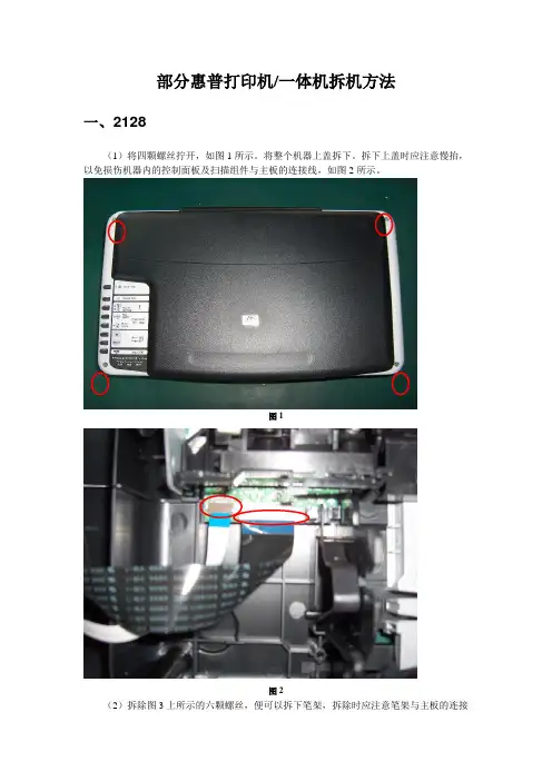
部分惠普打印机/一体机拆机方法一、2128(1)将四颗螺丝拧开,如图1所示。
将整个机器上盖拆下。
拆下上盖时应注意慢抬,以免损伤机器内的控制面板及扫描组件与主板的连接线,如图2所示。
图1图2(2)拆除图3上所示的六颗螺丝,便可以拆下笔架,拆除时应注意笔架与主板的连接线。
如图3所示。
图3(3)将后挡纸板取下,拆下最右边的清洁单元,然后拧下中间的螺丝和左边的卡子,便可以拆除整个进纸单元。
如图4所示。
图4(4)拧下螺丝,拆除马达,便可以取下主板。
如图5所示。
图5(5)取下整个玻璃板,便可以拆下扫描头组件,取下玻璃板时应注意控制面板下的数据线。
如图6所示。
图6二、3508/3608(1)将图1所示的控制面板按图2所示的黄色箭头方向打开。
图1图2(2)将图3中红圈中的螺丝拧下来,取下话筒下边的盖子。
图3 (3)拧下图4中2个红圈处的螺丝。
图4 (4)将图5中3个孔处的螺丝拧下来。
图5(5)将图6中红圈处的螺丝拧下来,并把后挡板按图6中黄色箭头的方向取下来,就可以拿下中间的壳了。
图6(6)拔掉图7、图8中所示的各连接到板上的数据线。
图6图7(7)把固定板的螺丝拧下来,就可以把板取下来了。
如图8红圈所示。
图8(8)将图9红圈处的铁板取下来,取下时要小心两边的卡子。
图9(9)将扫描组件取下来的时候注意图10中两个红圈处的卡子。
图10 (10)然后即可拆卸机器。
如图11、图12所示。
图11图12打印机下半部分的拆卸方法参见DJ3000系列。
如图13所示。
图13三、5328(1)取下机器的白色外盖。
如图1、图2所示。
图1将这个白色的盖取下来图2(2)将控制面板的外盖取下来。
如图3、图4所示。
图3图4(3)将图5中红圈处的2个小堵塞物拿下来,这里有2颗螺丝。
图5(4)将2颗螺丝拧下来,就可以取下控制面板了。
如图6所示。
图6(5)将固定侧盖的螺丝拧下来。
如图7所示。
图7(6)取下侧盖时注意机器低部的卡子。
如图8所示。
图8(7)取下白色的盖子。
hp1005硒鼓2612a加粉图解1.加粉之前,需要把废粉完全清除,磁辊上的粉尽量用皮老鼠弄干净,如果加入的粉和原来的粉不一样,两个混在一起,很可能打印出来的效果有底灰。
2.磁辊部分:⑴磁辊两边都有个塑料辊套,加粉的时候注意不要弄坏,也不要忘记不装,如果不装或者坏掉,可能发生的效果是:不装的一边打印后有鱼鳞状粉底。
⑵磁辊的一边有个黄色的圈状铜丝,好像是接地把,注意不要把它弄弯,或者压成别的状,因为它的不良很可能影响到打印效果的深浅度(与原效果对比)。
3.橡胶辊:个人认为,如果以前打印效果好的话,加粉的时候不要擦试橡胶辊,就算很脏也不要管它,可以用皮老鼠吹下。
加粉后如果出趾嵯虺鱿值暮诘溃徽派厦娑嘤?道的(鼓芯坏的话应该是四道),应该考虑下橡胶辊的问题。
4.鼓芯:取出的鼓芯尽量与工具隔离开,小心用工具碰到,因为大家都知道,鼓芯这个东西及其娇贵,不小心碰到很可能就报废了,要非常小心。
简单说这些,哪里不对的,或者需要补充的,请大家说说。
最后提醒下,给客户加粉之前最好先打印个测试页,看看效果是不是很好,不好的给他们说明。
如果上去就盲目的加粉,等加好了,效果不好,或者是该换鼓芯了,你再给客户说,客户绝对不会承认,他们会认为你加粉加坏的,纵使你有理,也说不清。
惠普M1005MFP一体机采用的2612A硒鼓,同时也在下列HP打印机或一体机中通用。
所以,该硒鼓加粉图对下列机器型号通用。
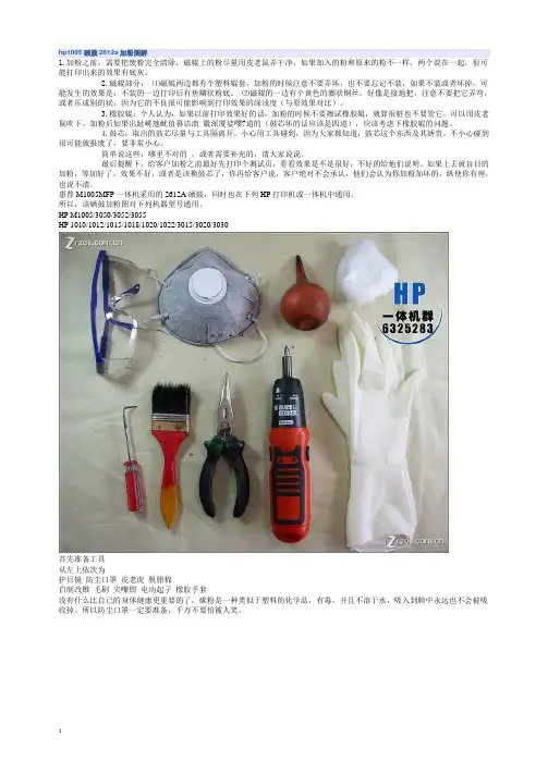
HP M1005/3050/3052/3055HP 1010/1012/1015/1018/1020/1022/3015/3020/3030首先准备工具从左上依次为护目镜防尘口罩皮老虎脱脂棉自制改锥毛刷尖嘴钳电动起子橡胶手套没有什么比自己的身体健康更重要的了,碳粉是一种类似于塑料的化学品,有毒,并且不溶于水,吸入到肺中永远也不会被吸收掉。
所以防尘口罩一定要准备,千万不要怕被人笑。
左-----------------------------------------------------------------------------右。
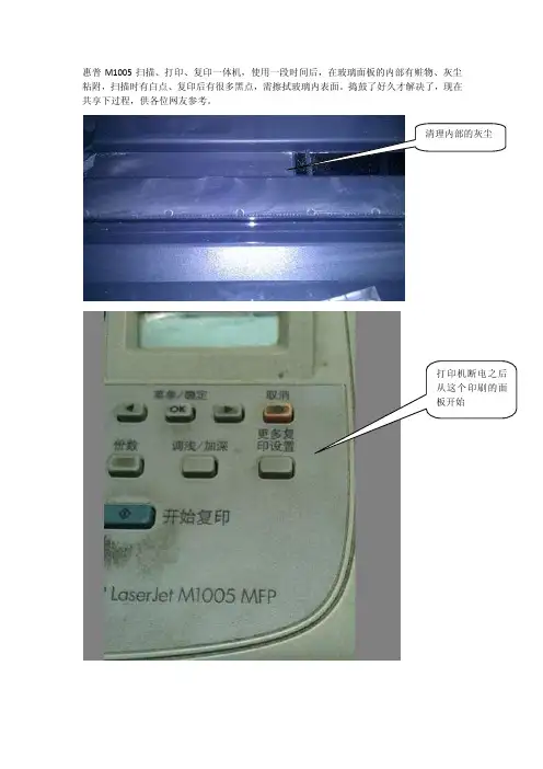
惠普M1005扫描、打印、复印一体机,使用一段时间后,在玻璃面板的内部有赃物、灰尘
粘附,扫描时有白点、复印后有很多黑点,需擦拭玻璃内表面。
捣鼓了好久才解决了,现在
共享下过程,供各位网友参考。
清理内部的灰尘
打印机断电之后
从这个印刷的面
板开始
用刀片撬开这个
塑料皮,并用十
字口的螺丝钉拧
开;撬开后还可
粘贴紧密的。
拧开螺丝后,内
部的卡扣如图,
往放纸的一侧轻
拉即可取下。
将这个数据线轻
轻拔出,防止清
理过程中损坏接
头。
安装回时注
意有触角的面相
互接触,否则控
制面板上会没显
示的。
然后用很小的内
六角扳手拧开这
个面上的7个螺
钉。
拧万螺丝后在背
面有三个卡扣,
用内六角扳手等
轻轻顶一下即可
撬开。
到此,即可翻开玻璃进行清理。
最后逆向安装回原即可。
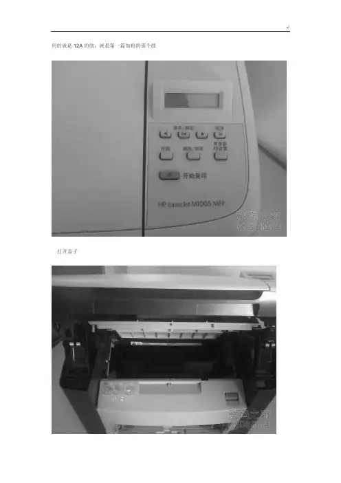
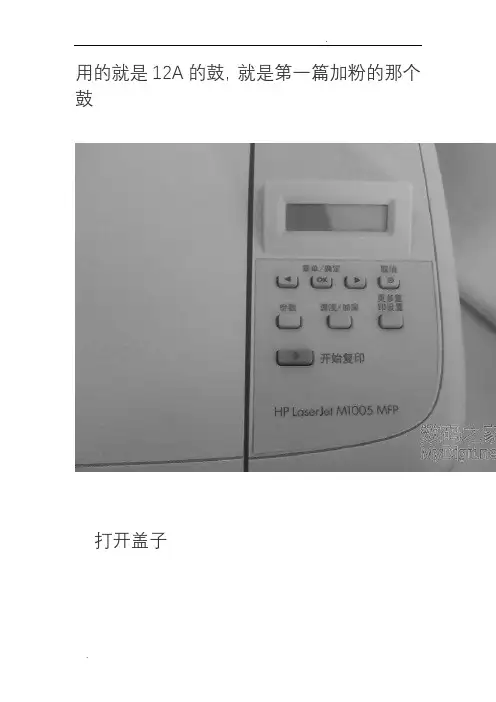
用的就是12A的鼓,就是第一篇加粉的那个鼓
打开盖子
这是用来开关的,左边一个,右边一个
首先就是擦下这个,看见上面那个卡口没有
往上顶一下,就可以下下来了
然后是卡最上面那个板子的,连着卡鼓的齿轮。
右边往下按,往右就可以抽出来
在来下后背
看见那3个螺丝,下下来后,双手托着下面,抬一下,就可以拿下来这是连着面板的2条线
一条黑的,一条白的
在来下侧盖,看见下面的那个卡口了吧,顶一下,在来扒上面的就很轻松
下来了
这边是管面板的
轻轻一抽就可以了,从这里拿出来
上面第二层盖子一翻就开了
这是卡全面口子的
先把这按下去,在从上左右2边往上拉,一起用劲往后抽就出来了
把这边的线全部抽掉
就是这样了
下左边2个螺丝,右边一个
往上一拉就出来了。
m105墨泵更换教程
1、更换墨盒之前我们需要购买好匹配的惠普M1005墨盒,因为不匹配的墨盒是无法使用的,一般在网上或者惠普官网都可以买到。
2、更换墨盒的时候,注意要先将打印机断电,然后打开打印机前段的外壳,我们就可以看到墨盒部分。
3、轻轻取下旧墨盒,然后对准墨盒接口装到打印机上,然后再盖上打印机前段的外壳。
4、墨盒安装完成之后,我们还需要测试一下打印机是否可以正常工作,检查打印是否清晰,确认无误后就完成了墨盒的更换工作。
用的就是12A的鼓,就是第一篇加粉的那个鼓
打开盖子
这是用来开关的,左边一个,右边一个
首先就是擦下这个,看见上面那个卡口没有
往上顶一下,就可以下下来了
然后是卡最上面那个板子的,连着卡鼓的齿轮。
右边往下按,往右就可以抽出来
在来下后背
看见那3个螺丝,下下来后,双手托着下面,抬一下,就可以拿下来
这是连着面板的2条线
一条黑的,一条白的
在来下侧盖,看见下面的那个卡口了吧,顶一下,在来扒上面的就很轻松
下来了
这边是管面板的
轻轻一抽就可以了,从这里拿出来
上面第二层盖子一翻就开了
这是卡全面口子的
先把这按下去,在从上左右2边往上拉,一起用劲往后抽就出来了
把这边的线全部抽掉
就是这样了
下左边2个螺丝,右边一个
往上一拉就出来了。
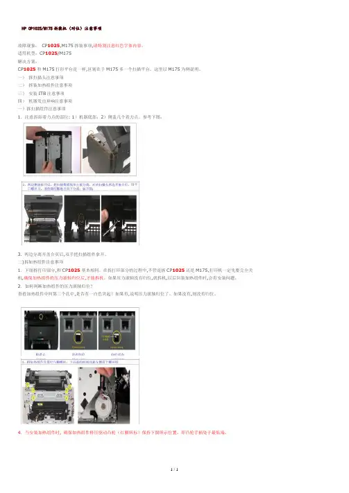
HP CP1025/M175拆装机(对位)注意事项故障现象:CP1025,M175拆装事项,请特别注意红色字体内容。
适用机型:CP1025/M175解决方案:CP1025和M175打印平台是一样,区别在于M175多一个扫描平台。
这里以M175为例说明。
一)拆扫描头注意事项二)拆装加热组件注意事项三)安装ITB注意事项四)机器发出异响注意事项一)拆扫描组件注意事项1.注意拆卸着力点的部位: 1)机器底部;2)侧盖几个着力点。
参考下图:3. 两边分离开盖合页后,双手把扫描组件拿开。
二)拆加热组件注意事项1.下面拆打印部分,和CP1025基本相同。
在拆打印部分的过程中,不管是拆CP1025还是M175,打印机一定先要完全关机,确保加热组件的压力滚轴归位后,才能拆机。
如果压力滚轴没有归位,就拆机,以后回装加热组件时,会有安装问题。
2.如何判断加热组件的压力滚轴归位?查看加热组件中间第二个孔中,是否有一白色突起?如果有,说明压力滚轴归位了。
如果没有,则没有归位。
4.当安装加热组件时, 确保加热组件释压驱动凸轮(红圈所标)保持下图所示位置。
即凸轮手柄处于最低端。
三)拆装ITB注意事项安装的ITB备件分两种来源:1)从机器上拆下来的ITB备件;2)从SRFR系统申请到的ITB备件。
1. 从机器上拆下来的ITB备件安装注意事项:回装ITB时,需注意ITB左边(从后面看)有个白色齿轮。
白色齿轮缺口应与侧面的一个小黑三角标记对齐,然后回装ITB。
红圈为白色齿轮缺口和小黑三角对应好的位置,如下图:2)安装SRFR到货新ITB注意事项:a.新到货ITB需要释放TIB弹簧。
可以用一字螺丝刀,把两边画圈的地方向内顶开,这时ITB会自动把皮带拉紧,如下图:b.安装新的ITB皮带时,注意左侧白色齿轮缺口应与小黑三角标记对应。
如果此白色齿轮和小黑三角没有对好,装上去后会发出咔咔声响。
c.新到的ITB备件有个桔红色的卡子,可以不用取出。
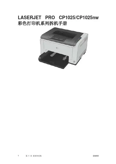
LASERJET PRO CP1025/CP1025nw 彩色打印机系列拆机手册1 拆卸和更换简介拆卸和更换战略静电放电必备工具维修方法拆卸和更换流程简介本章只介绍了现场可更换部件(FRU)的拆卸和更换方法。
FRU 的更换步骤一般只是拆卸步骤的相反顺序。
为了帮助您顺利地更换部件,我们针对部分困难或重要的更换流程提供了相关注意事项和技巧。
惠普不支持修复单个子装置或者在组件级别执行故障排除。
请记下每个螺钉的长度、直径、颜色、类型和位置。
在重新组装的过程中,请务必将每颗螺钉都安装回最初的位置。
如果线束连接错误或者不牢固,可能会干扰其它内部组件,或者自身损坏或断开。
磨损或被挤压的线束线找起来可能非常困难。
更换线束时,请一定使用随机提供的线环、矛状头(lance point)或线束导板和固定器。
拆卸和更换战略警告!开始维修产品之前,请首先关闭打印机,等待5 秒钟的时间,然后拔下电源线。
如果不遵守本警告的规定,除了会损坏打印机,还可能导致严重的人身伤害。
排除故障的过程中,部分功能检查操作只能在打印机通电的情况下才能完成。
但是,拆卸部件时必须断开电源。
在激光/扫描仪装置的保护盖已拆除的情况下,不得运行或者维修打印机。
反射光束虽然看不见,但会损伤您的眼睛。
钣金零件的边缘可能非常锋利。
处理这些零件时请注意不要割伤自己。
小心:进行拆卸或安装时,请不要弯曲或折叠扁形软电缆(FFC)。
请不要展开FFC中预先叠起的部分。
您必须将所有FFC 完全插入相应的接口中。
如果FFC 没有完全插入接口中,可能导致PCA 中出现短路。
注意:安装自攻螺钉时,首先将其向逆时针方向旋转,让它与现有的螺纹形状相符,然后再顺时针旋转拧紧。
请不要拧得太紧。
如果自攻螺钉孔已磨损,请维修螺钉孔,或者更换受影响的装置。
提示:请注意,本章部分照片中所展示的已拆除组件在维修打印机的过程中可能并不需要拆除。
如有必要,请首先拆卸本文于各个流程开始时列出的组件,然后再维修打印机。
打印机打印的字不清晰了,自己动手换个硒鼓不求人小伙伴们在用打印机的时候是不是遇到打印机没碳粉的时候需要换硒鼓,可是却发现不会换硒鼓,怎么办。
今天小编就教大家来试试怎么快速换硒鼓吧。
其实很简单的,只要查到打印机的型号就能查到硒鼓的型号啦,然后直接换就行了。
今天小编就以自己的打印机惠普M1005为例。
首先可以在打印机的盖板上或者打印机的背面能够查看到打印机的型号。
看到开始复印下面的那一行字了吗?“HP LaserJet M1005 MFP”这是惠普M1005的打印机。
那么对应的打印机硒鼓也是有型号的哦,硒鼓的型号也会标注在硒鼓上面的。
看到下面的那个黑色的粗体12A旁边有一行小的字体Q2612A,这个就是硒鼓的完整型号啦。
如果实在不知道硒鼓型号,可以去网上搜下打印机的型号就会有对应的硒鼓型号出来。
换硒鼓的时候首先要找到打印机的鼓仓,一般鼓仓都在盖板下面的。
而且鼓仓上面的盖板都是可以打开的,像M1005的打印机,鼓仓的盖板下有一个开关,直接按下开关就会弹出来的。
弹出来我们就能看到硒鼓啦,就是那个黑色的带把手的长长的不知道怎么描述的东东。
打开鼓仓后,看到小编的大拇指摁着的那个把手没,只要用手提着把手然后先向上拉。
拉到硒鼓弹出来后就再往胸前拉就可以把硒鼓抽出来啦,记住不是向上提了啊,是像前啊,不要霸蛮啊,否则搞坏了支架别怪我哦。
其实这种小型打印机的硒鼓都是先向上提就解锁了,解锁后再往前抽出轨道就OK啦。
装的时候也是一样,有把手的一面对准自己,然后轻轻的往里面推,知道听到“咔”的一声,同时推不动的时候就说明硒鼓装进去了,此时盖上盖板就可以啦。
是不是很简单呢,赶快自己动手试试吧,以后办公室里的硒鼓可以自己换了。
打开打印碳粉盒盖2,在打印机的背面,用平口螺丝刀释放2标签(1)。
▲图1-1 拆卸左侧盖过程图1 - 1拆卸左侧盖(1 - 2)3,将盖从打印机。
右侧盖1,打开打印碳粉盒盖。
2,删除托盘2。
3,在打印机的前面,流行前沿的右侧盖在保留标签。
▲图1 - 2拆卸右侧盖4,将盖从打印机上拆除背盖1,拆除托盘2。
2,拆下左侧和右侧盖。
3,拆下四个螺钉(1)。
▲图3拆卸后盖(1 / 2)4,提示打印机,它取决于其前。
5,释放的标签(2)在打印机背面的右侧。
6,打开双通道门(3)。
7,滑动盖向打印机右边的明确的标签(1)的双工器托盘(双模式只)。
▲图1 - 4拆卸后盖(2 / 2)8,将盖板上直从打印机。
双工托盘(惠普激光p2015d,p2015dn,和p2015x打印机。
1,拆下左侧,右侧盖,和后盖。
2,拉release-tab双工托盘(1)释放双工托盘磁铁。
▲图1-5拆卸双工托盘3,拉出双工托盘。
取出上盖1,拆下左侧,右侧盖,背盖,托盘和双工器。
2,拆下螺钉(1)在打印机的背面。
▲图1 - 6拆卸上盖(1 - 4)3,删除一个螺丝(1)在左侧的打印机,并删除一个螺丝(2)的右侧打印机的。
▲图1 - 7拆卸上盖(2 - 4)4,释放控制面板电缆(1)的左侧的打印机。
▲图1 - 8拆卸上盖(3 - 4) 5,电梯上盖关闭打印机。
▲图1 - 9拆卸上盖(4 - 4) 控制面板1,删除所有覆盖。
2,在底盖的顶部,拆下螺钉(1)。
▲图1 - 10拆卸控制面板(1,2) 3。
拆下控制面板电线从电线导游。
▲图1 - 11拆卸控制面板(2,2)。
HP50005100激光打印机定影膜更换方法图解
HP5000/5100 激光打印机定影膜更换方法图解故障现象:打印机能正常工作,但打印件中部有一条白色带。
故障原因:打印机定影膜破损。
故障排除:更换定影膜。
详细过程如下:
HP5100 A3激光打印机
第一步:拆出定影组件
1、向内推打印机背面的纸架钮,放下纸架;
2、松开纸架吊带,将纸架放到底,向后抽出纸架。
3、拧下两个六角头螺丝,小心地向后抽出定影组件。
4、定影组件拆离打印机。
第二步:拆卸定影组件1、破损的定影膜。
2、在定影组件的一侧抽出两个插件,松开线卡,拧下两个小螺丝。
3、在定影组件的另一侧松开线卡,并拧下一个小螺丝。
4、松开两侧的弹簧。
5、拆下定影组件上盖。
6、将整个上辊向上取出。
7、下辊也有破损,若不更换,定影膜会再次破损。
拆下左侧齿轮,
松开两个白色轴套,向上取出下辊。
8、定影组件拆除完毕。
第三步:更换并恢复
1、将导电橡胶齿轮套入新下辊,套入白色轴套,并将下辊放入定影组件架。
2、除掉破损的定影膜,细心地将上辊上的积碳清除干净,不要刮伤。
在上辊外表面较突出部位均匀地抹一层硅脂。
把上辊左边的固定底座取下,小心地将定影膜套入(一定注意方向,深色导电边朝左)。
安装到位后,转动一下定影膜,若活动自如,则安装成功。
否则,卸下定影膜重新涂抹硅脂,再安装。
直至活动自如。
3、按拆卸的反过程,依次还原各个部件。
安装完毕,上机测试。
6Removal and replacementThis chapter provides information about the following topics.●Removal and replacement strategyENWW59Removal and replacement strategyNOTE Some photos show a device other than the HP LaserJet M1005 MFP. Repair andreplacement procedures in this chapter are for the HP LaserJet M1005 MFP and are not affectedby cosmetic differences (for example, the color of the covers) shown in these photos.This chapter documents the removal and replacement of field replaceable parts (FRUs) only.Reinstallation is generally the reverse of removal. Occasionally, notes and hints are included to provide directions for difficult or critical replacement procedures.AdmonitionsWARNING!Unplug the power cord from the power outlet (at the wall receptacle) beforeattempting to service the device. It this warning is not followed, severe injury can result. Certainfunctional checks during troubleshooting must be performed with power supplied to the device.However, the power supply should be disconnected during removal.Sheet-metal and plastic edges in the device can be sharp. Use caution when servicing this device.Never operate or service the device with the protective cover removed from the laser/scannerassembly. The invisible reflected beam can damage your eyes.CAUTION The device contains components that are sensitive to electrostatic discharge (ESD).Always perform service work at an ESD-protected workstation. If an ESD-protected workstationis not available, discharge body static by grasping the print engine chassis before touching anESD-sensitive component. Ground the print engine chassis before servicing the device.CAUTION Do not bend or fold the FFCs during the removal or reinstallation process.NOTE For service purposes, the upper part of the HP LaserJet M1005 MFP is, in effect, the"scanner" and the lower part is the "printer". Together, they also act as a photocopier, but theservice description here is simplified by referring to copier functionality only when specificallynecessary.Tip To install a self-tapping screw, first turn it counterclockwise to align it with the existing threadpattern, then carefully turn it clockwise to tighten. Do not overtighten.Required tools●#2 Phillips screwdriver with magnetic tip●Small flat-blade screwdriver●#8 and #10 torx screwdrivers●Needle-nose pliers●ESD mat (if available)●Penlight (optional)●Long flat-blade screwdriver (optional)60Chapter 6 Removal and replacement ENWWCAUTION Do not use a pozidrive screwdriver or any motorized screwdriver. These can damagescrews or screw threads on the device.Before performing service●If possible, print a configuration page (to record customer settings) and menu structure report.See Troubleshooting tools on page 140.●Remove all media from the device and remove the media input tray. See Media input trayon page 78.●Turn off the power by using the power switch.●Unplug the power cord from the wall receptacle.●Place the device on an ESD mat, if available. If an ESD-protected workstation is not available,discharge body static and ground the print engine chassis before servicing the device.●Remove the print cartridge.After performing service●Replace the print cartridge.●Reload the input tray with media.●Restore customer configuration settings.Parts removal orderUse the following diagrams to determine which parts of the device must be removed before servicing. ENWW Removal and replacement strategy61Control panel overlayControl panelScanner lidScanner assemblyLink assembly and scanner springPrinter separation padPrint cartridgePrinter pickup rollerTransfer rollerMedia input trayPrinter side coversRear cover and fuser coverPower supplyScanner assemblyPrint-cartridge doorFront coverScanner support frameEngine controller unitLaser/scanner assemblyMain motorFuser assemblyPaper pickup assemblyFront coverFormatterFigure 6-1 Parts removal order for the HP LaserJet M1005 MFP62Chapter 6 Removal and replacement ENWWFlatbed lid1.Open the flatbed lid.2.Lift the lid up and off of the scanner assembly to remove it.NOTE The lid must be in the fully opened position to release the hinge pins from the hingebrackets.Figure 6-2 Remove the flatbed lid (1 of 2)Tip When the flatbed lid is reinstalled, make sure that the hinge pins are fully seated inthe hinge brackets on the scanner flatbed assembly.ENWW Removal and replacement strategy63Control-panel overlayUse a small flat blade screwdriver to lift up the control-panel overlay and then remove it.CAUTION Be careful to not damage the overlay if it will be reinstalled after servicing the device.Figure 6-3 Remove the control-panel overlay64Chapter 6 Removal and replacement ENWWControl panelTip Lift up the control-panel overlay to see the screw. See Control-panel overlay on page 64.Figure 6-4 Remove the control panel (1 of 4)1.Remove one screw.Figure 6-5 Remove the control panel (2 of 4)ENWW Removal and replacement strategy652.Slide the control panel toward you and slightly lift up the control panel.Figure 6-6 Remove the control panel (3 of 4)3.Disconnect one flat flexible cable (callout 1) and remove the control panel.Figure 6-7 Remove the control panel (4 of 4)Tip When reinstalling the control panel, make sure the rear mounting tabs on the bottomrear of the control panel engage the holes in the scanner assembly, and then slide the controlpanel toward the rear of the device.66Chapter 6 Removal and replacement ENWWScanner assembly1.Remove the flatbed lid. See Flatbed lid on page 63.2.Remove one screw (callout 1).Figure 6-8 Remove the scanner assembly (1 of 11)3.Gently pry the side cover away from the device chassis.Figure 6-9 Remove the scanner assembly (2 of 11)ENWW Removal and replacement strategy674.Release the side cover bottom locking tab and remove the cover.Figure 6-10 Remove the scanner assembly (3 of 11)5.Disconnect two FFCs (callout 2).Figure 6-11 Remove the scanner assembly (4 of 11)68Chapter 6 Removal and replacement ENWW6.Push the print-cartridge-door button and raise the scanner assembly.Figure 6-12 Remove the scanner assembly (5 of 11)7.Remove the shield and the FFCs from the guide (callout 3).NOTE The screw (callout 4) that fastens the shield to the device chassis does not needto be removed.Figure 6-13 Remove the scanner assembly (6 of 11)8.Release the tab on the gear-drive arm bracket and carefully flex it away from the scanner assembly.Figure 6-14 Remove the scanner assembly (7 of 11)9.Pull the bracket toward the right side of the device until its mounting tabs clear the holes in thescanner assembly.Figure 6-15 Remove the scanner assembly (8 of 11)e a small flat-blade screwdriver to release the hinge tabs on each front hinge (right side shown).WARNING!When the front hinges are disengaged, the scanner assembly can easily falloff of the device base if it is rotated too far toward the back of the product.CAUTION Do not push too hard on the link tabs or the tabs might break.Figure 6-16 Remove the scanner assembly (9 of 11)11.Remove the hinges (right side shown).Figure 6-17 Remove the scanner assembly (10 of 11)12.Rotate the scanner assembly toward the rear of the product until the rear hinges clear the chassishinge pins. Lift the scanner assembly up and off of the device base.Figure 6-18 Remove the scanner assembly (11 of 11)Device separation padNOTE Some photos show a device other than the HP LaserJet M1005 MFP. Repair andreplacement procedures in this chapter are for the HP LaserJet M1005 MFP and are not affected by cosmetic differences (for example, the color of the covers) shown in these photos.1.At the back of the device, remove two screws (callout 1).Figure 6-19 Remove the device separation pad (1 of 2)2.Remove the device separation pad and frame.Figure 6-20 Remove the device separation pad (2 of 2)Print cartridgeCAUTION To prevent damage, do not expose the print cartridge to direct or bright light. Cover it with a piece of paper.1.Push the print-cartridge-door button to release the print-cartridge door.Figure 6-21 Remove the print cartridge (1 of 2)2.Pull the print cartridge up and out of the device.Figure 6-22 Remove the print cartridge (2 of 2)Device pickup roller1.Remove the print cartridge and locate the device pickup roller. See Print cartridge on page 74.Figure 6-23 Remove the device pickup roller (1 of 5)2.Gently release the small, white tabs on each side of the pickup roller by pushing them away fromthe roller, and then rotate the roller away from the mounting frame.CAUTION Do not touch the black-sponge transfer roller inside the device. Touching thetransfer roller can damage the device.Use gentle pressure to release the small white tabs to avoid breaking them.Figure 6-24 Remove the device pickup roller (2 of 5)3.Gently pull the roller up and out of the device.Figure 6-25 Remove the device pickup roller (3 of 5)4.Circular and rectangular pegs on each side of the pickup roller fit into corresponding slots on thepickup-roller mounting frame to prevent the roller from being incorrectly installed. Position the replacement pickup roller in the slots on the pickup-roller frame.Figure 6-26 Remove the device pickup roller (4 of 5)5.Rotate the top of the pickup roller into position until the white tabs on each side of the roller snapinto place.Figure 6-27 Remove the device pickup roller (5 of 5)Media input trayNOTE Some photos show a device other than the HP LaserJet M1005 MFP. Repair andreplacement procedures in this chapter are for the HP LaserJet M1005 MFP and are not affected by cosmetic differences (for example, the color of the covers) shown in these photos.1.Open the media input tray lid.Figure 6-28 Remove the media input tray (1 of 3)2.Slide the adjustable media guides (callout 1) to the center of the tray.Figure 6-29 Remove the media input tray (2 of 3)3.Depress the pickup-tray locking tabs (callout 2) to release the media input tray, and then pull it outand away from the device.Figure 6-30 Remove the media input tray (3 of 3)Transfer rollerCAUTION Do not touch the black-sponge portion of the transfer roller. Skin oils deposited on the transfer roller might cause print-quality problems.Be very careful not to break the paper guide that is removed during replacement of the transfer roller. Because the paper guide is not a FRU, the entire device will have to be replaced.1.Open the print-cartridge door and remove the print cartridge.2.Release the two locking tabs on the paper guide and rotate the guide up.Figure 6-31 Remove the transfer roller (1 of 3)3.The clamps on the paper guide fit over the bearings on each end of the transfer roller. Do not touchthe black-sponge portion of the transfer roller. Grasp the right end of the paper guide and pull the clamp off the bearing on the right side of the transfer roller. Then slide the clamp slightly to the right, and the left clamp will slide off the left bearing.Figure 6-32 Remove the transfer roller (2 of 3)4.Squeeze the two small tabs on the transfer roller.Figure 6-33 Remove the transfer roller (3 of 3)Device side coversNOTE Some photos show a device other than the HP LaserJet M1005 MFP. Repair andreplacement procedures in this chapter are for the HP LaserJet M1005 MFP and are not affected by cosmetic differences (for example, the color of the covers) shown in these photos.NOTE The procedure for removing the right-side and left-side covers is identical, with theexception of the location of the screw that fastens the cover to the device. The right-side cover is shown in the following procedure.1.Remove one screw (callout 1; the right-side cover uses a black screw). Callout 2 is on the left-sidecover.Figure 6-34 Remove the device side covers (1 of 3)2.Release the locking tabs on the upper-back (callout 2).Figure 6-35 Remove the device side covers (2 of 3)3.Release the bottom tab (callout 3).CAUTION When removing the left-side cover hang the device off of the table to gainaccess to the bottom tab. This prevents the I/O shield from being damaged if the right-sidecover is off and the device is tilted too far up.Figure 6-36 Remove the device side covers (2 of 3)4.Slightly rotate the back-side of the right cover away from the device, and then slide it toward thefront of the device to release it.Figure 6-37 Remove the device side covers (3 of 3)Tip When reinstalling the device side covers, hook the front of the cover onto the deviceand rotate the rear of the cover over the device chassis.Print-cartridge doorNOTE Some photos show a device other than the HP LaserJet M1005 MFP. Repair andreplacement procedures in this chapter are for the HP LaserJet M1005 MFP and are not affected by cosmetic differences (for example, the color of the covers) shown in these photos.1.Remove the scanner assembly. See Scanner assembly on page 67.2.Fully open the print-cartridge door and gently pull downward on both print-cartridge swing arms(callout 1) to release them (the left arm is shown disengaged).CAUTION Be careful when releasing the swing arms. They can easily break.Figure 6-38 Remove the print-cartridge door (1 of 2)3.Rotate the door toward the back of the device and then lift it up and off of the device.Figure 6-39 Remove the print-cartridge door (2 of 2)Rear cover and fuser coverNOTE Some photos show a device other than the HP LaserJet M1005 MFP. Repair andreplacement procedures in this chapter are for the HP LaserJet M1005 MFP and are not affected by cosmetic differences (for example, the color of the covers) shown in these photos.1.Remove the right-side and left-side covers. See Device side covers on page 822.Remove one screw (callout 1).Figure 6-40 Remove the rear cover and fuser cover (1 of 3)3.Release the two rear-cover locking tabs (callout 2). Rotate the bottom of the rear cover up andaway from the device, and remove it.Figure 6-41 Remove the rear cover and fuser cover (2 of 3)4.Rotate the bottom of the fuser cover away from the device, and remove the fuser cover.Figure 6-42 Remove the rear cover and fuser cover (3 of 3)Front coverNOTE Some photos show a device with the same print engine as the HP LaserJet M1005 MFP.Repair and replacement procedures in this chapter are for the HP LaserJet M1005 MFP and are not affected by cosmetic differences (for example, the color of the covers) shown in these photos.1.Remove the right-side and left-side covers. See Device side covers on page 82.2.Release the lower right-side front-cover locking tab and slightly pry the lower-right corner of thefront cover away from the device.Figure 6-43 Remove the front cover (1 of 3)3.Release the lower left-side front-cover locking tab (located near the corner of the power supply)and slightly pry the lower-left corner of the front cover away from the device.Figure 6-44 Remove the front cover (2 of 3)4.Pry up and pull out on the front cover to release it from the device. Remove the front cover.Figure 6-45 Remove the front cover (3 of 3)Tip Note the location of the front-cover tabs (callout 1). Make sure that all of the front cover tabs are fully seated when the cover is installed.Figure 6-46 Reinstalling the front coverInstalling the scanner cushionsNOTE Some photos show a device other than the HP LaserJet M1005 MFP. Repair andreplacement procedures in this chapter are for the HP LaserJet M1005 MFP and are not affected by cosmetic differences (for example, the color of the covers) shown in these photos.1.Open the print-cartridge door.2.Place a scanner cushion in the wells on the scanner support frame (callout 1). Use the eraser endof a pencil or use an ink pen with the cap on to seat each cushion in its well.Figure 6-47 Installing the scanner cushionsPower supply1.Remove the rear cover and fuser cover. See Rear cover and fuser cover on page 86.2.Disconnect one spade connector (callout 1) and remove three screws (callout 2).Reinstallation tip The center screw in callout 2 is a ground screw and is a different typethan the others. When reinstalling the power supply, make sure that this screw is used inthe center hole.Figure 6-48 Remove the power supply (1 of 3)3.Disconnect one FFC (callout 3) and six wire-harness connectors (callout 4) and remove them fromthe wire loom.CAUTION Do not bend or fold the FFCs during the removal or reinstallation process.Figure 6-49 Remove the power supply (2 of 3)4.Remove four screws (callout 5) and remove the wire-harness from the wire loom (callout 6) andunclip the wire loom from the chassis (remove the wire-harness from this wire loom). Remove the power supply.Figure 6-50 Remove the power supply (3 of 3)Tip When reinstalling the power supply, make sure that the wire-harnesses are routed correctly.Formatter1.Remove the right cover. See Device side covers on page 82.2.Disconnect two connectors (callout 1) and three FFCs (callout 2).Figure 6-51 Remove the formatter (1 of 2)3.Remove four screws (callout 3) and remove the formatter.Figure 6-52 Remove the formatter (2 of 2)Scanner support frameNOTE Some photos show a device other than the HP LaserJet M1005 MFP. Repair andreplacement procedures in this chapter are for the HP LaserJet M1005 MFP and are not affected by cosmetic differences (for example, the color of the covers) shown in these photos.1.Remove the following assemblies●Scanner assembly. See Scanner assembly on page 67.●Left cover. See Device side covers on page 82.●Rear cover and fuser cover. See Rear cover and fuser cover on page 86.●Print cartridge door. See Print-cartridge door on page 85.●Front cover. See Front cover on page 88.2.Remove six screws (callout 1).CAUTION Be careful not to drop any screws into the device.NOTE If the scanner support frame is turned over after it is removed, the two scannercushions (callout 2) might fall out and be misplaced.Figure 6-53 Remove the scanner support frame (1 of 3)3.Rotate the gear-drive bracket until the retainer on the gear-drive arm aligns with the opening in thebracket, and remove the bracket.Figure 6-54 Remove the scanner support frame (2 of 3)4.Lift the scanner support frame up and off of the device.Figure 6-55 Remove the scanner support frame (3 of 3)Engine controller unit1.Remove the following assemblies.●Scanner assembly. See Scanner assembly on page 67.●Left cover. See Device side covers on page 82.●Rear cover and fuser cover. See Rear cover and fuser cover on page 86.●Print cartridge door. See Print-cartridge door on page 85.●Front cover. See Front cover on page 88.●Scanner support frame. See Scanner support frame on page 95.2.Remove four screws (callout 1).Figure 6-56 Remove the ECU (1 of 6)e a long flat-blade screwdriver to disengage the engine control unit (ECU) shield retainer hooks(left hook shown; callout 2) inside the device. Push the hooks into the device to disengage them.Figure 6-57 Remove the ECU (2 of 6)4.Disconnect one FFC (callout 3) from the formatter.Figure 6-58 Remove the ECU (3 of 6)5.Disconnect one FFC (callout 4) from the power supply.CAUTION Do not bend or fold the FFCs during the removal or reinstallation process.Figure 6-59 Remove the ECU (4 of 6)6.Disconnect one FFC (callout 5) from the ECU and the wire-harness connector to the main motor(callout 6). Remove one screw (callout 7). Release the wire-harness (callout 8) from the retainer slot on the ECU.Tip Unweave this wire-harness from additional wire looms to have enough slack todisengage it from the slot on the ECU.Figure 6-60 Remove the ECU (5 of 6)7.Carefully remove the ECU from the device. As it is removed, unweave the wire-harnesses andFFCs from the wire looms, and disconnect one wire-harness connector (callout 9) from the laser/ scanner. Remove the ECU.Figure 6-61 Remove the ECU (6 of 6)Laser/scanner assembly1.Remove the following assemblies.●Scanner assembly. See Scanner assembly on page 67.●Left cover. See Device side covers on page 82.●Rear cover and fuser cover. See Rear cover and fuser cover on page 86.●Print cartridge door. See Print-cartridge door on page 85.●Front cover. See Front cover on page 88.●Scanner support frame. See Scanner support frame on page 95.●ECU. See Engine controller unit on page 98.2.Remove four screws (callout 1). Remove the laser/scanner assembly.Figure 6-62 Remove the laser/scanner assemblyMain motor1.Remove the following assemblies.●Scanner assembly. See Scanner assembly on page 67.●Formatter. See Formatter on page 94.●Left cover. See Device side covers on page 82.●Rear cover and fuser cover. See Rear cover and fuser cover on page 86.●Print cartridge door. See Print-cartridge door on page 85.●Front cover. See Front cover on page 88.●Scanner support frame. See Scanner support frame on page 95.●ECU. See Engine controller unit on page 98.●Laser/scanner assembly. See Laser/scanner assembly on page 102.2.Disconnect the motor wire-harness connector (callout 1) and remove one screw (callout 2).Figure 6-63 Remove the main motor (1 of 2)3.Remove one screw (callout 3), and remove the main motor.Figure 6-64 Remove the main motor (2 of 2)Fuser1.Remove the following assemblies.●Scanner assembly. See Scanner assembly on page 67.●Left cover. See Device side covers on page 82.●Rear cover and fuser cover. See Rear cover and fuser cover on page 86.●Print cartridge door. See Print-cartridge door on page 85.●Front cover. See Front cover on page 88.●Scanner support frame and chassis reinforcement plate. See Scanner support frameon page 95.2.Disconnect cables from near the top of the engine power assembly and disconnect the largegrounding wire from the back of the device.3.Disengage the wire-harnesses from the wire retainers to release the fuser assembly.4.Remove three screws (callout 1; this figure shows the delivery-sensor PCB removed, which is notnecessary).Figure 6-65 Remove the fuser assembly (1 of 2)5.Lift the fuser assembly at the right and remove the fuser assembly.Figure 6-66 Remove the fuser assembly (2 of 2)NOTE When replacing the fuser assembly, be sure to transfer the delivery-sensor PCB from the old fuser to the new one.Figure 6-67 Fragile tab on fuser assemblyPaper-pickup assembly1.Remove the following assemblies.●Scanner assembly. See Scanner assembly on page 67.●Left cover. See Device side covers on page 82.●Rear cover and fuser cover. See Rear cover and fuser cover on page 86.●Print cartridge door. See Print-cartridge door on page 85.●Front cover. See Front cover on page 88.●Transfer roller. See Transfer roller on page 80.●Fuser. See Fuser on page 105.2.Unplug and remove any additional wire-harnesses as necessary to release the paper-pickupassembly. Unplug and remove the wire from the solenoid to the formatter.3.Remove six screws (callout 1) and remove the assembly.Figure 6-68 Remove the paper-pickup assembly。
LASERJET PRO M1536 MFP 拆机手册1 拆卸和更换简介 (3)拆卸和更换战略 (3)静电放电 (4)必备工具 (4)维修方法 (4)拆卸和更换流程 (8)简介本章只介绍了现场可更换部件(FRU)的拆卸和更换方法。
FRU 的更换步骤一般只是拆卸步骤的相反顺序。
为了帮助您顺利更换部件,我们针对部分困难或重要的更换流程提供了相关注意事项和技巧。
惠普不支持修复单个子装置或者解决组件级问题。
请记下每个螺钉的长度、直径、颜色、类型和位置。
在重新组装的过程中,请务必将每颗螺钉都安装回最初的位置。
如果线束连接错误或者不牢固,可能会干扰其它内部组件,或者自身损坏或断开。
磨损或被挤压的线束线找起来可能非常困难。
更换线束时,请一定使用随机提供的线环、矛状头或线束导杆和固定夹。
拆卸和更换战略警告!开始维修产品之前,请首先关闭打印机,等待5 秒钟的时间,然后拔下电源线。
如果不遵守本警告的规定,可能导致严重的人身伤害,并损坏打印机。
解决问题的过程中,部分功能检查操作只能在打印机通电的情况下才能完成。
拆卸部件时必须断开电源。
在激光/扫描仪装置的保护盖已拆除的情况下,不得运行或者维修打印机。
反射光束虽然看不见,但会损伤您的眼睛。
钣金零件的边缘可能非常锋利。
处理这些零件时请注意不要割伤自己。
注意:进行拆卸或安装时,请不要弯曲或折叠扁形软电缆(FFC)。
请不要展开FFC 中预先叠起的部分。
您必须将所有FFC 都完全插入各自的接口中。
如果FFC 没有完全插入接口中,可能导致PCA 中出现短路。
注意:安装自攻螺钉时,首先将其向逆时针方向旋转,让它与现有的螺纹形状相符,然后再顺时针旋转拧紧。
请不要拧得太紧。
如果自攻螺钉孔已磨损,请维修螺钉孔,或者更换受影响的装置。
提示:为了清楚起见,本章提供了一些显示已拆除组件的图片。
这些组件在维修产品时可能无需拆卸。
如必要,可在维修产品前,拆卸流程开头列出的组件。
静电放电注意:有些部件对静电放电(ESD)非常敏感。
hp1005扫描排线更换教程
一,拧掉机子后面的所有螺丝。
二,打开机子侧面的塑料护壳。
三,拔掉扫描仪的线(如机子后面对着你就是你左手边塑料盖那里的线两根排线一根普通线)
四,撑起上盖(就是扫描部件)。
五,拧掉你看见的一个导电线螺丝去掉支撑杆(就是撑起扫描仪的那两个黑色杆)。
六,去掉硒鼓带动齿轮杆(最后一个了解扫描仪的塑料杆)。
七,可以去掉扫描仪了八,去掉后你就能看见机子后面的铁板它上面是塑料盖去掉塑料盖拆下螺丝去掉铁板就可以看见定影部件了!下面拆掉定影组建就可以了!拧调固定定影的螺丝和线就好了。
安装方法
1、首先正确连接打印机与电脑,然后网页搜索惠普官网点击进入
2、点击页面上方支持,选择软件与驱动程序
3、点击打印机
4、输入M1005,点击下方出现的全名
5、弹出下载界面,我们点击下载,记住安装路
6、然后我们点击桌面左下角的开始按钮,打开控制面板
7、点击硬件和声音
8、点击设备和打印机下的添加打印机
9、然后安装驱动,点击从“从磁盘安装”即可。
5、驱动安装后,打印机就和电脑连接成功了(在控制面板--设备和打印机可以看到)。
用的就是12A的鼓,就是第一篇加粉的那个鼓
打开盖子
这是用来开关的,左边一个,右边一个
首先就是擦下这个,看见上面那个卡口没有
往上顶一下,就可以下下来了
然后是卡最上面那个板子的,连着卡鼓的齿轮。
右边往下按,往右就可以抽出来
在来下后背
看见那3个螺丝,下下来后,双手托着下面,抬一下,就可以拿下来
这是连着面板的2条线
一条黑的,一条白的
在来下侧盖,看见下面的那个卡口了吧,顶一下,在来扒上面的就很轻松
下来了
这边是管面板的
轻轻一抽就可以了,从这里拿出来
上面第二层盖子一翻就开了
这是卡全面口子的
先把这按下去,在从上左右2边往上拉,一起用劲往后抽就出来了
把这边的线全部抽掉
就是这样了
下左边2个螺丝,右边一个
往上一拉就出来了。