SmartLineSTR700SmartLine远传法兰变送器-霍尼韦尔
- 格式:pdf
- 大小:2.41 MB
- 文档页数:25

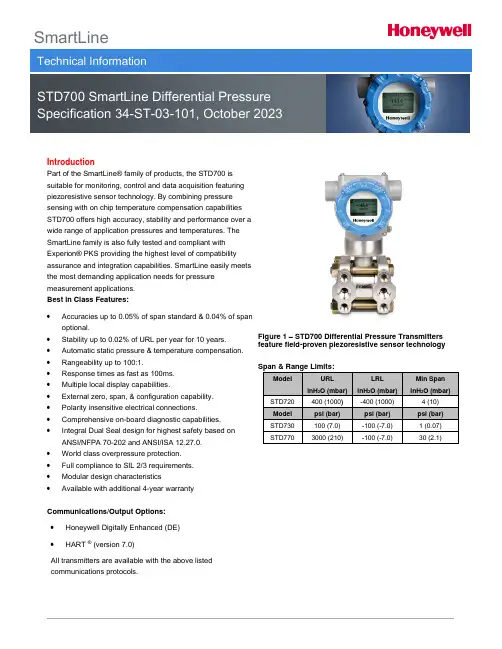
SmartLineIntroductionPart of the SmartLine® family of products, the STD700 issuitable for monitoring, control and data acquisition featuring piezoresistive sensor technology. By combining pressuresensing with on chip temperature compensation capabilitiesSTD700 offers high accuracy, stability and performance over a wide range of application pressures and temperatures. TheSmartLine family is also fully tested and compliant withExperion® PKS providing the highest level of compatibilityassurance and integration capabilities. SmartLine easily meets the most demanding application needs for pressuremeasurement applications.Best in Class Features:•Accuracies up to 0.05% of span standard & 0.04% of span optional.•Stability up to 0.02% of URL per year for 10 years. •Automatic static pressure & temperature compensation. •Rangeability up to 100:1.•Response times as fast as 100ms.•Multiple local display capabilities.•External zero, span, & configuration capability. •Polarity insensitive electrical connections. •Comprehensive on-board diagnostic capabilities. •Integral Dual Seal design for highest safety based on ANSI/NFPA 70-202 and ANSI/ISA 12.27.0.•World class overpressure protection.•Full compliance to SIL 2/3 requirements.•Modular design characteristics•Available with additional 4-year warranty Communications/Output Options:•Honeywell Digitally Enhanced (DE)•HART ® (version 7.0)All transmitters are available with the above listed communications protocols. Figure 1 – STD700 Differential Pressure Transmitters feature field-proven piezoresistive sensor technologyDescriptionThe SmartLine family pressure transmitters are designed around a high performance piezo-resistive sensor. This one sensor actually integrates multiple sensors linking process pressure measurement with on-board static pressure (DP Models) and temperature compensation measurements. This level of performance allows the ST 700 to replace most competitive transmitters available today.Unique Indication/Display OptionThe ST 700 modular design accommodates a standard alphanumeric LCD display or a unique advanced graphics LCD display with many unparalleled features.Standard LCD Display Features•Modular (may be added or removed in the field).•Supports HART protocol variant.•0, 90,180, & 270 degree position adjustments.•Four configurable screens.•Standard and custom measurement units available. •Display calculated flow (square root) value in addition to analog output signal.• 2 Lines 6 digits PV (9.95H x 4.20W mm) 8 Characters. •Write protect Indication.•Built-in Basic Device Configuration through Internal or External Buttons – Range/Engineering Unit/Loop Test/Loop Calibration/Zero /Span Setting.•Multiple language capabilities (EN, RU).Advanced LCD Display Features•Modular (may be added or removed in the field)•0, 90,180, & 270 degree position adjustments. •Standard and custom measurement units available. •Up to eight display screens with 3 formats are possible. •Large PV with Bar Graph or PV with Trend Graph. •Configurable screen rotation timing (1 to 30 sec). •Display calculated flow (square root) value in addition to analog output signal.•Unique “Health Watch” indication provides instant visibility of diagnostics.•Multiple language capability (EN, DE, FR, IT, ES, RU, TR, CN, & JP).DiagnosticsSmartLine transmitters all offer digitally accessible diagnostics which aid in providing advanced warning of possible failure events minimizing unplanned shutdowns, providing lower overall operational costs. System Integration•SmartLine communications protocols all meet the most current published standards for HART/DE. •Integration with Honeywell’s Experion PKS offers the following unique advantages.o Tamper reportingo FDM Plant Area Views with Health summarieso All ST 700 units are Experion tested to provide the highest level of compatibility assurance. Configuration ToolsIntegral Three Button Configuration OptionSuitable for all electrical and environmental requirements, SmartLine offer the ability to configure the transmitter and display via three externally accessible buttons when either display option is selected. Zero/span capabilities are also optionally available via these buttons with or without selection of a display option.Handheld ConfigurationSmartLine transmitters feature two-way communication and configuration capability between the operator and the transmitter. All Honeywell transmitters are designed and tested for compliance with the offered communication protocols and are designed to operate with any standards compliant handheld configuration device, such as Honeywell Versatilis Configurator.Personal Computer ConfigurationOn a personal computer or laptop, Honeywell Field Device Manager (FDM) Software and FDM Express can be used for managing HART device configurations.Modular DesignTo help contain maintenance & inventory costs, all ST 700 transmitters are modular in design supporting the user’s ability to replace meter bodies, add indicators or change electronic modules without affecting overall performance or approval body certifications. Each meter body is uniquely characterized to provide in-tolerance performance over a wide range of application variations in temperature and pressure and due to the Honeywell advanced interface, electronic modules may be swapped with any electronics module without losing in-tolerance performance characteristics.Modular Features•Meter body replacement•Exchange/replace electronics/comms modules*•Add or remove integral indicator*•Add or remove lightning protection (terminal connection)** Field replaceable in all electrical environments (including IS) except flameproof without violating agency approvals.With no performance effects, Honeywell’s unique modularity results in lower inventory needs and lower overall operating costs.Performance SpecificationsReference Accuracy (conformance to +/-3 Sigma)Zero and span may be set anywhere within the listed (URL/LRL) range limitsAccuracy at Specified Span, Temperature and Static Pressure Effects: (conformance to +/-3)Total Performance (% of Span):Total Performance = +/-√(Accuracy)2 + (Temp Effect)2+ (Static Line Pressure Effect)2Total Performance Examples (for comparison): standard accuracy, 5:1 Turndown, up to 50o F (28o C) shift & up to 1000 psi Static PressureSTD720 @ 80 inH2O: 0.218% of spanSTD730 @ 20 psi: 0.199 % of spanSTD770 @ 600 psi: 0.196 % of spanTypical Calibration Frequency:Calibration verification is recommended every two (2) years.Notes:1. Terminal Based Accuracy – Includes combined effects of linearity, hysteresis and repeatability. Analog output adds 0.005% of span.2.For zero based spans and reference conditions of: 25o C (77o F), 0 psig static pressure, 10 to 55% RH and 316SS barrier diaphragm.Operating Conditions – All Models1 LCD Display operating temperature -20︒C to +70︒C. Storage temperature -30︒C to 80︒C.2Silicone 704 minimum temperature rating is 0o C (32o F). CTFE minimum temperature rating is -40︒C (-40︒F).NEOBEE ® M-20 minimum temperature rating is -15o C (5o F). NEOBEE ® is a registered trademark of Stepan Company.3 Short term equals 2 hours at 70︒C (158︒F).4MAWP applies for temperatures -40 to 125︒C. Static Pressure Limit is de-rated to 3,000 psi for -26︒C to -40︒C. for all models. Use of graphite o-rings de-rates transmitter to 3,625 psi. Use of 1/2:” process adaptors with graphite o -rings de-rates transmitter to 3,000 psi. 5Consult factory for MAWP of ST 700 transmitters with CRN approval.Figure 2 - Supply voltage and loop resistance chart & calculationsPerformance Under Rated Conditions – All ModelsMaterials Specifications (see model selection guide for availability/restrictions with various models)3 Monel 400 or UNS N044004 Supplied as 316 SS or as Grade CF8M, the casting equivalent of 316 SS.5 Carbon Steel heads are zinc-plated and not recommended for water service due to hydrogen migration. For that service, use 316 stainless steel wetted Process Heads.6 Hastelloy C-276 or UNS N10276. Supplied as indicated or as Grade CW12MW, the casting equivalent of Hastelloy C-276Communications Protocols & DiagnosticsHART ProtocolVersion: HART 7Honeywell Digitally Enhanced (DE)DE is a Honeywell proprietary protocol which provides digital communications between Honeywell DE enabled field devices and hosts.Standard DiagnosticsST 700 top level diagnostics are reported as either critical or non-critical and are readable via the DD/DTM/FDI tools or integral display. All critical diagnostics will appear on the Advanced and Standard integral displays, and some non-critical diagnostics will also appear on the Advanced integral display. Some of the diagnostics are listed below.Critical Diagnostics•Electronics Module Fault.•Meter body Memory Corruption.•Config Data Corruption.•Electronics Module Diagnostics Failure.•Meter body Critical Failure.•Sensor Communication Timeout.Non-Critical Diagnostics•Electronics Module Fault.•Display Failure.•Electronics Module Comm Failure.•Meter body Excess Correct.•Sensor Over Temperature.•Fixed Current Mode.•PV Out of Range.•No DAC Compensation.•Tamper Attempt Alarm.Refer to the product user manual for comprehensive list of diagnostics and details.Hazardous Areal CertificationsII 1/2 G Ex db IIC T6..T5 Ga/Gb II 2 D Ex tb IIIC T95 Intrinsically Safe: SIRA 12ATEX2233XII 1 G Ex ia IIC T4 GaII 2 D Ex ia IIIC T125FISCO Field Device (Only for FF Option)II 3 G Ex ec IIC T4 GcZone 2, Intrinsically Safe: SIRA12ATEX4234XII 3 G Ex ic IIC T4 GcFISCO Field Device (Only for FF Option) II 3 G Ex ic IIC T4 GcFlameproof: CSAE 22UKEX1021XII 1/2 G Ex db IIC T6..T5 Ga/Gb II 2 D Ex tb IIIC T95 Intrinsically Safe: CSAE 22UKEX1021XII 1 G Ex ia IIC T4 GaII 2 D Ex ia IIIC T125FISCO Field Device (Only for FF Option)II 3 G Ex ec IIC T4 GcZone 2, Intrinsically Safe: CSAE22UKEX1009XII 3 G Ex ic IIC T4 GcFISCO Field Device (Only for FF Option) II 3 G Ex ic IIC T4 GcNotes:1. Operating Parameters:Voltage = 11 to 42 VDC = 9 to 32 V (FF) Current = 4-20 mA Normal = 30 mA (FF)2. Intrinsically Safe Entity Parametersa. Analog/ DE/ HART Entity Values:Vmax = Ui = 30V Imax = Ii = 105mA Ci = 4.2nF Li = 984 uH Pi = 0.9WTransmitter with Terminal Block Revision E or LaterVmax = Ui = 30V Imax = Ii = 225mA Ci = 4.2nF Li = 0 Pi = 0.9WNote: Transmitter with Terminal Block Revision E or laterThe revision is on the label that is on the module. There will be two lines of text on the label:•First is the Module Part #: 50049839-001 or 50049839-002•Second line has the supplier information, along with the REVISION:XXXXXXX-EXXXX, THE “X” is production related, THE POSITION of the “E” IS THE REVISION.b. Foundation Fieldbus Entity ValuesVmax = Ui = 30V Imax= Ii = 180mA Ci = 0nF Li = 984 uH Pi = 1WTransmitter with Terminal Block Revision F or LaterVmax = Ui = 30V Imax = Ii = 225mA Ci = 0nF Li = 0 Pi = 1 WFISCO Field DeviceVmax = Ui = 17.5V Imax = Ii = 380 mA Ci = 0nF Li = 0 Pi = 5.32 WNote: Transmitter with Terminal Block Revision F or laterThe revision is on the label that is on the module. There will be two lines of text on the label:•First is the Module Part #: 50049839-003 or 50049839-004•Second line has the supplier information, along with the REVISION:XXXXXXX-EXXXX, THE “X” is production related, THE POSITION of the “E” IS THE REVISION.Approval CertificationsOther Certification OptionsMaterialsNACE MRO175, MRO103, ISO15156Mounting & Dimensional DrawingsReference Dimensions:millimetersinchesMounting ConfigurationsFigure 3 – Typical mounting configurations of STD720, STD730 & STD770 for reference onlyDimensionsFigure 4 – Typical mounting dimensions of STD720, STD730 & STD770 for reference onlyModel Selection GuideModel Selection Guides are subject to change and are inserted into the specifications as guidance only.Model STD700Differential Pressure TransmitterModel Selection Guide:34-ST-16-101, Issue 35Price equals the s um of prices for all selections made.123STD770STD730o STD720Left side/Right side as viewed from the customer connection perspective3NAMUR Output Limits 3.8 - 20.5mAdc can be configured by the customer or select custom configuration Table VcSTD770STD730STD720The PM option is available on all Smartline Pressure Transmitter process wetted parts such as process heads, flanges, bushings and vent plugs except plated carbon steel process heads and flanges. PM option information is also available on diaphragms except STG and STA in-line construction pressure transmitters.For more informationTo learn more about SmartLine PressureTransmitters visit Or contact your Honeywell Account ManagerProcess Solutions Honeywell1250 W Sam Houston Pkwy S Houston, TX 77042Honeywell Control Systems LtdHoneywell House, Skimped Hill Lane Bracknell, England, RG12 1EB34-ST-03-101 October 2023©2023 Honeywell International Inc.Shanghai City Centre, 100 Jungi Road Shanghai, China 20061Sales and ServiceFor application assistance, current specifications, ordering, pricing, and name of the nearest Authorized Distributor, contact one of the offices below.ASIA PACIFICHoneywell Process Solutions, Phone: + 800 12026455 or +44 (0) 1202645583 (TAC) hfs-tac-*********************AustraliaHoneywell LimitedPhone: +(61) 7-3846 1255 FAX: +(61) 7-3840 6481 Toll Free 1300-36-39-36 Toll Free Fax: 1300-36-04-70China – PRC - Shanghai Honeywell China Inc.Phone: (86-21) 5257-4568 Fax: (86-21) 6237-2826SingaporeHoneywell Pte Ltd.Phone: +(65) 6580 3278 Fax: +(65) 6445-3033South KoreaHoneywell Korea Co Ltd Phone: +(822) 799 6114 Fax: +(822) 792 9015EMEAHoneywell Process Solutions, Phone: + 800 12026455 or +44 (0) 1202645583Email: (Sales)*************************** or (TAC)*****************************WebKnowledge Base search engine http://bit.ly/2N5VldiAMERICASHoneywell Process Solutions, Phone: (TAC) (800) 423-9883 or (215) 641-3610(Sales) 1-800-343-0228Email: (Sales)*************************** or (TAC)*****************************WebKnowledge Base search engine http://bit.ly/2N5VldiSpecifications are subject to change without notice.。
I Connected IndustriaISMARTLINE PRESSURE SELECTION GUIDELINESRedefining Smart.SmartLine Pressure TransmittersHoneywell’s SmartLine® pressure measurement system sets the standard with its industry-leading total performance, even in harsh process environments. With the best control system integration and unique features such as modularity, a graphics display and universal terminals, SmartLine offers the lowest total cost of ownership.Leading PerformanceSmartLine provides better performance with industry leading accuracy, response time and stability. When combined with Honeywell’s proven static pressure and temperature compensation, the unbeatable total performance is better than 0.12% of span under actual process conditions.Lowest Total Cost of Ownership• H oneywell’s unique approach to modularity helps reduce maintenance costs and make repairs safer and faster. With the ability to repair the transmitter in place, the need to break a process line connection is avoided, even in an intrinsically safe environment. And with no need to stock complete units, inventory costs are lower.• A n advanced graphics display and three button external configuration option provide capabilities for field operators to more efficiently perform tasks,solve problems and avoid errors with no need for a handheld device. The display shows rich graphics, bar graphs, trends and messages from the control room.• W ith SmartLine’s universal terminals, wiring can be reversed without damaging or affecting the normal operation of the transmitter. This avoids costly rework on large installations where multiple contractors may use different wiring standards and eliminates return trips to re-wire “incorrectly wired” devices.SmartLine Connection Advantage• T ransmitter Messaging allows the operator to send and display custom messages to the display so field operators can quickly identify the right transmitter and task.•M aintenance Mode Indication displays a message on the display that the transmitter and/or the loop is in a mode suitable for maintenance. • U nique Tamper Reporting notifies the control room that an attempt to change a write-protected configuration has been made or that the write protection has been switched off.•F ield Device Manager (FDM) is Honeywell’s centralized asset management system for smart field device configuration and maintenance. When SmartLine data is integrated into FDM, users can create hierarchical screen displays for quick and easy views of device health from areas of the plant or process.• W ith comprehensive testing, Honeywell provides trouble-free integration for faster startups and reliability. The tests even include other suppliers’ configuration tools.ST800ST700SMV800 Performance CharacteristicsAccuracy • U p to 0.0375% span standard• 0.025% span optional highaccuracy • B asic: up to 0.065% of span• S tandard: up to 0.05% of span•P V1 DP – up to 0.04% of span• P V2 SP – up to 0.0375% of span• P V3 PT – 0.2 °C RTD – Pt 100• P V4 – mass flow accuracyup to 0.6%Stability• U p to 0.01% per year for ten years• B asic: up to 0.025% per year for5 years• S tandard: up to 0.02% per yearfor 5 years• U p to 0.0625% of URL per yearResponse Time• A s fast as 80 ms• A s fast as 100 ms•A s fast as 144 ms for DP (PV1) Total Performance• U p to 0.12%• U p to 0.2%• M ass flow performance is up to 0.6% Turndown Ratios up to 400:1• T urndown ratios up to 400:1• T urndown ratios up to 100:1• T urndown ratios up to 400:1 Compound Characterized Ranges• Y es• Y es• Y esTemperature & Static PressureCompensated• Y es• Y es• Y esProduct Features & OptionsMeasured Parameters• D ifferential pressure staticpressure • D ifferential pressure staticpressure• D ifferential pressure, staticpressure, process temperatureCaluclated Parameters• V olume flow• V olume flow• V olume flow, mass flow Support for Flow Algorithms• N A• N A• A SME MFC-3M, ISO5167, Gost8.586, AGA3, ASME MFC 14MSupport for Flow Elements• N A• N A• O rifice, Venturi, Flow Nozzle,Pitotube, IFO, Standard V cone,Wafer cone, WedgeHART® 7, DE & F OUNDATION™Fieldbus Communication Protocols• Y es• Y es• D E, HART 7Universal Terminals• Y es• S tandard: Yes• Y esModular Design Components• S imple faster repairs with lessdowntime • S imple faster repairs withless downtime• S imple faster repairs withless downtimeSmartLine Connection Advantage with Experion®• T ransmitter Messaging*• M aintenance Mode Indication• T amper Alerts*• F DM Plant Area Views• C omprehensive Experionintegration testing• T amper Alerts* (Standard only)• F DM Plant Area Views• T ransmitter Messaging*• M aintenance Mode Indication• T amper Alerts*• F DM Plant Area Views• C omprehensive Experionintegration testingSIL 2 Certified/SIL 3Capable Standard• Y es• Y es• N o Certified for Dual Seal Compliance• Y es• Y es• Y esComprehensive & AdvancedDiagnostics• Y es• Y es• Y esUser Interface Options• O ptional basic alphanumeric display• O ptional advanced graphics display• M ultiple PV display screens includingbar graph and trend displays• C omprehensive diagnostic messages• S upports transmitter messagingand maintenance mode indication• C omprehensive EDDs & DTMsfor remote configuration• O ptional external 3-buttonprogramming capability • S T700 Basic: supports Standarddisplay with internal and/orexternal 2-button configurationST700 Standard: supportsStandard display with internal2-button configuration / Basicdisplay with external three buttonconfiguration• Diagnostic notifications•C omprehensive EDDs & DTMsfor remote configuration• O ptional external two (Basic)or three (Standard) buttonprograming capability• N A•O ptional advanced graphics display• M ultiple PV display screens includingbar graph and trend displays• C omprehensive diagnostic messages• S upports transmitter messagingand maintenance mode indication• C omprehensive EDDs & DTMs forremote configuration• O ptional external 3-buttonlimited programming capOptional Extended Warranties• 1, 2, 3, 4 and 15 year warranties• 1, 2, 3 and 4 year warranties• 1, 2, 3, 4 and 15 year warranties *Also compatible with other HART 7 enabled hostsStandard, basic or advanced digital display as determined by the application requirementsUniversal or traditional wiring terminal boards with standard or lightning-protected optionsIt takes only a matter of minutes to replace the electronics, even in the field under power with no re-calibration required. This avoids the time-consuming procedure of removing a sensor from a pipeline or network, particularly in highly critical processes.Best of all, Honeywell’s unique modularity reduces inventory requirements and lowers overall operating costs.LOWER YOUR TOTAL COST OF OWNERSHIPWith Plug-In Modules, Users Can Easily Add or UpgradeAll SmartLine Pressure Transmitters are modular in design, making it easy to replace hardware, add indicators, change electronic modules or even meter bodies without affecting overall performance or impinging on approval body certifications.Flexible ConfigurationIn addition to configuring with any hand-helddevice or through asset management DTMs, users can configure the transmitters through externally accessible buttons, even in an intrinsically safe, Class I, Div. 1 environment.Now, whether on the bench or in the field, configure, change tag information, change languages and even more without needing a handheld device.SMARTLINE PRESSURE SELECTION GUIDEModel Types, Ranges and SpansModelUpper Range Lower Range Max. SpanUnitsStandard Accuracy % of Span Turndown CapabilityTwo- or three-button external configurationField-exchangeable communication modules to deploy HART , Honeywell Digital Enhanced (DE) or FOUNDATION Fieldbus communicationAdvanced Graphics LCD Display• U p to eight separate screens with three formats to meet unique display requirements: process variable, bar graph and trend• F ull library of engineering units with the ability to add custom units• Configurable screen rotation timing • Supports multiple languages • Two diagnostic indications• 90-degree position adjustments to facilitate all installation positions.For more informationTo learn more about Honeywell’s SmartLine Pressure Transmitters, visit /smartlineor contact your Honeywell account manager. Honeywell Process Solutions512 Virginia DriveFort Washington, PA 19034 USAHoneywell House, Arlington Business Park Bracknell, Berkshire, England RG12 1EB17 Changi Business Park Central 1 Singapore 486073 SmartLine® and Experion® are registered trademarks of Honeywell International Inc. HART® is a registered trademark andF OUNDATION™ Fieldbus is a trademark of the FieldComm Group.PO-16-01-ENG | 11/16©2016 Honeywell International Inc.。
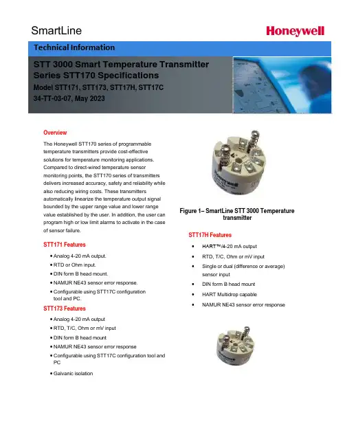
SmartLineOverviewThe Honeywell STT170 series of programmabletemperature transmitters provide cost-effectivesolutions for temperature monitoring applications.Compared to direct-wired temperature sensormonitoring points, the STT170 series of transmittersdelivers increased accuracy, safety and reliability while also reducing wiring costs. These transmittersautomatically linearize the temperature output signalbounded by the upper range value and lower range value established by the user. In addition, the user can program high or low limit alarms to activate in the case of sensor failure.STT171 Features• Analog 4-20 mA output.• RTD or Ohm input.• DIN form B head mount.• NAMUR NE43 sensor error response.• Configurable using STT17C configurationtool and PC.STT173 Features• Analog 4-20 mA output• RTD, T/C, Ohm or mV input• DIN form B head mount• NAMUR NE43 sensor error response• Configurable using STT17C configuration tool and PC• Galvanic isolation Figure 1– SmartLine STT 3000 TemperaturetransmitterSTT17H Features•HART™/4-20 mA output•RTD, T/C, Ohm or mV input•Single or dual (difference or average)sensor input•DIN form B head mount•HART Multidrop capable•NAMUR NE43 sensor error responseSTT 3000 Smart Temperature Transmitter Series STT170 SpecificationsModel STT171, STT173, STT17H, STT17C34-TT-03-07, May 2023Technical InformationDimensions (all models)WiringSTT171 STT173Input:Input:RTD, 2-wire RTD, 3-wire RTD, 4-wire TC, internal CJCRTD,2-wire RTD,3-wire Resistance,2-wire Resistance,3-wireTC, external CJC mV Resistance, 2-wire Resistance, 3-wireOutput:2-wire installationResistance, 4-wireOutput:2-wire installationSTT17HThe STT17C configures the STT171, STT173 and STT17H. The intuitive graphical user interface of the STT17C virtually eliminates the need for operator training after installation on a PC. The STT17C includes all software and transmitter interface hardware necessary to configure the STT171, STT173 and STT17H in non-hazardous work environments.WARNING: The STT17C is not approved for use in Hazardous work environments.System Requirements:Windows® 98SE, ME, 2000 and XP with the following recommendations:Memory: 16 MBDisplay resolution: 800 x 600Hard disk space: 12 MB**or 50%of upper range value,whichever is greater***reference temperature24o COPERATING CONDITIONS APPROVALSAmbient temperature, rated……….……-40 to 85o C (-40 to 185o F)Observed Authority requirements:Standard: Humidity……………………………………0 to 95% RH (non-cond.)EMC 2004/108/EC Vibration…………………………………Max 4g over 25 to 100Hz Emmission and immunity ……… EN 61326ATEX94/9/EC…........................................ EN50014,EN50020, ELECTRICAL INPUT SPECIFICATIONS EN502811-1and EN50284 Supply voltage………………………………8to30VDC FM,ASCN…............................................. 3600,3611,3610Power supply voltage effect………………≤0.005%of span per VDC CSA,CAN/CSA ......................................... C22.2No.157,E60079-11, Warm-up time…………………………..….5min UL913Response time(programmable)…………0.33to60sec Ex/I.S.approval:KEMA06ATEX0042X…………………………II1GD,T80o C…T105o C CURRENT OUTPUT SPECIFICATIONS EEx ia IIC T4.T6Signal output range…………………………4to20mA Max.amb.Temperature for T4….................... 85o CUpdate time………………………………… 135msec Max.amb.Temperature for T6….................... 60o CLoad resistance………....……...…………≤(V supply-8)/0.023A Applicable in zone…..................................... 0,1,2,20,21or220to870οFM,applicable in…………………………………IS,CL I,DIV1,Grp.A-D,T4…T6AEx ia IICALARM LEVELS NI,CL I,DIV2,Grp.A-D,T4...T6 Programmable...................................3.5to4mA downscale Entity,FM Installation Drawing No. (50016324)20 to 23 mA upscale CSA, applicable in.....................................IS,CL I, DIV 1, Grp. A-D, T4...T6 NAMUR NE43 Upscale.........................23 mA Ex ia IIC, AEx ia IIC NAMUR NE43Downscale....................3.5mA Entity,Installation Drawing No... (50016326)Ex/I.S.data:U i (max) .................................................... 30 VDCI i (max)...................................................... 120mADCP i (max) .................................................... 0.84WL i (max)..................................................... 10μHC i (max) .................................................... 1.0 nFUo (max) .................................................. 27 VDCIo (max).................................................... 7 mADCPo (max)................................................... 45m WLo(max) ................................................... 35 mHCo (max) .................................................. 90 nFSTT17H-BN Specification*whichever is greater; Total Reference Accuracy = Basic Accuracy + CJ Accuracy (T/C only)**or 50% of upper range value, whichever is greater*** reference temperature 24o COPERATING CONDITIONS APPROVALSAmbient temperature, rated…………...…. -40 to 85o C (-40 to 185o F) Observed Authority requirements: Standard: Humidity……………………………………0 to 95% RH (non-cond.) EMC 2004/108/EC Vibration…………………………………...…Max 4g over 25 to 100Hz Emmission and immunity ……… EN 61326Cold junction accuracy……………………±1.0o C ATEX94/9/EC… .................................................. EN60079-0,EN60079-15 ELECTRICAL INPUT SPECIFICATIONS Ex / I.S. approval:Supply Voltage....................................8 to 35 VDC KEMA 06 ATEX 0043 X..............................II 3 GD, T80o C...T105o C Power supply voltage effect.................. ≤ 0.005% of span per VDC EEx nA [L] IIC T4. T6 Warm-up time....................................30sec Applicable in zone... (2)Response time(programmable)…………1to60sec Max.amb.Temperature for T4…......................... 85o CGalvanic isolation………………………….1500VAC Max.amb.Temperature for T6…......................... 60o CCURRENT OUTPUT SPECIFICATIONS Vmax (V)Signal output range..................................... 4 to 20 mAUpdate time… ............................................. 440 msecLoad resistance(ν)...................................... ≤(V supply -8)/0.023A0 to 1174 νALARM LEVELSProgrammable…........................................ 3.5 to 4 mA downscale20 to 23 mA upscaleNAMUR NE43 Upscale…......................... 23 mANAMUR NE43Downscale…....................... 3.5 mA9STT 3000 Smart Temperature Transmitter STT171 Custom Configuration Data SheetCustomer P.O. NumberLine ItemModel NumberTag Number (max 15 char)Honeywell Sales Order NumberSensor Type:□Pt100□Ni100□OhmsOutput Values:4 mA Value: 20 mA Value: Response time:□o C□o F□Ohms □o C□o F□Ohms(0.33 – 60 sec)Output Limits:□Span (4 to 20 mA)□Max (3.5 to 23 mA)□Specify Low mA, High mA□NAMUR NE 43 (3.8 to 20.5 mA)Sensor Error Action:□Off□Specify mA□NAMUR NE 43 upscale (23 mA)□NAMUR NE 43 downscale (3.5 mA)10STT 3000 Smart Temperature TransmitterSTT173 Custom Configuration Data SheetCustomer P.O. NumberLine ItemModel NumberTag Number (max 15 char)Honeywell Sales Order NumberSensor Type:□Pt100 □Type B T/C Cold Junction Compensation:□Ni100 □Type E T/C □Internal□Type J T/C □External / Pt100Wiring: □Type K T/C □External / Ni100□2-wire □Type L T/C□3-wire □Type N T/C□4-wire □Type R T/C□Type S T/C□ Ohms □Type T T/C□mV □Type U T/C□Type W3 T/C□Type W5 T/COutput Values:4 mA Value: 20 mA Value: Response time:□o C □o C (1 – 60 sec)□o F □o□mV □mV□Ohms □OhmsOutput Limits:□Span (4 to 20 mA)□Max (3.5 to 23 mA)□Specify Low mA, High mA□NAMUR NE 43 (3.8 to 20.5 mA)Sensor Error Action:□Off□Specify mA□NAMUR NE 43 upscale (23 mA)□NAMUR NE 43 downscale (3.5 mA)STT17H Custom Configuration Data SheetCustomer P.O. NumberLine ItemModel NumberTag Number (max 15 char)Honeywell Sales Order NumberSensor Input:□Single Sensor□Duplex Sensor (Average)□Duplex Sensor (Differential)Sensor Type:□Pt100□Type B T/C Cold Junction Compensation:□Ni100□Type E T/C□Internal□Type J T/C□External / Pt100 Wiring: □Type K T/C□External / Ni100□2-wire□Type L T/C□3-wire□Type N T/C□4-wire□Type R T/C□Type S T/C□Ohms□Type T T/C□mV□Type U T/C□Type W3 T/C□Type W5 T/COutput Values:4 mA Value: 20 mA Value: Response time:□o C□o F□mV □Ohms □o C□o□mV□Ohms(1 – 60 sec)Output Limits:□Span (4 to 20 mA)□Max (3.5 to 23 mA)□Specify Low mA, High mA□NAMUR NE 43 (3.8 to 20.5 mA)Sensor Error Action:□Off□Specify mA□NAMUR NE 43 upscale (23 mA)□NAMUR NE 43 downscale (3.5 mA)Model Selection Guide (34-44-16-07)Model Selection Guides are subject to change and are inserted into the specifications as guidance only.Sales and ServiceFor application assistance, current specifications, pricing, or name of the nearest Authorized Distributor, contact one of the offices below.ASIA PACIFICHoneywell Process Solutions, (TAC) hfs-tac-********************* AustraliaHoneywell LimitedPhone: +(61) 7-3846 1255FAX: +(61) 7-3840 6481Toll Free 1300-36-39-36Toll Free Fax:1300-36-04-70China – PRC - Shanghai Honeywell China Inc.Phone: (86-21) 5257-4568Fax: (86-21) 6237-2826 SingaporeHoneywell Pte Ltd.Phone: +(65) 6580 3278Fax: +(65) 6445-3033South KoreaHoneywell Korea Co LtdPhone: +(822) 799 6114Fax: +(822) 792 9015 EMEAHoneywell Process Solutions,Phone: + 80012026455 or+44 (0)1344 656000Email: (Sales)***************************or(TAC)*****************************AMERICA’SHoneywell Process Solutions,Phone: (TAC) 1-800-423-9883 or215/641-3610(Sales) 1-800-343-0228Email: (Sales)***************************or(TAC)*****************************For more informationTo learn more about Temperature Transmitters,visit Or contact your Honeywell Account ManagerProcess SolutionsHoneywell1250 W Sam Houston Pkwy S Houston, TX 77042Honeywell Control Systems Ltd Honeywell House, Skimped Hill Lane Bracknell, England, RG12 1EB Shanghai City Centre, 100 Jungi Road Shanghai, China 20061 34-TT-03-07May 2023©2023 Honeywell International Inc.。
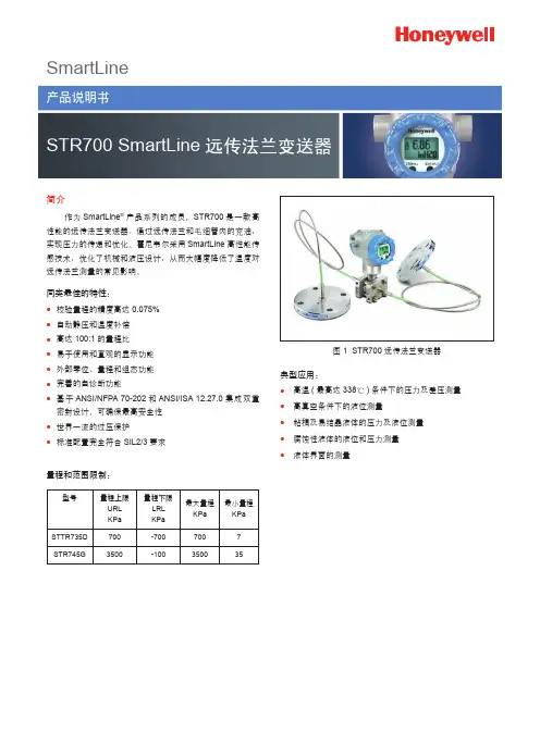
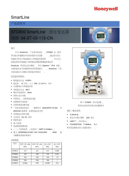
SmartLine简介作为SmartLine ®产品系列的成员,STR700是一款高性能的远传法兰变送器。
通过远传法兰和毛细管内的充油,实现压力的传递和优化。
霍尼韦尔采用SmartLine 高性能传感技术,优化了机械和液压设计,从而大幅度降低了温度对远传法兰测量的常见影响。
同类最佳的特性:● 校验量程的精度高达0.075%● 自动静压和温度补偿● 高达100:1的量程比● 易于使用和直观的显示功能● 外部零位、量程和组态功能● 完善的自诊断功能●基于ANSI/NFPA 70-202和ANSI/ISA 12.27.0集成双重密封设计,可确保最高安全性● 世界一流的过压保护●标准配置完全符合SIL2/3要求量程和范围限制:图1 STR700远传法兰变送器典型应用:●高温(最高达338℃)条件下的压力及差压测量●高真空条件下的液位测量●粘稠及易结晶液体的压力及液位测量●腐蚀性液体的液位和压力测量●液体界面的测量型号量程上限URL KPa 量程下限LRL KPa 最大量程KPa 最小量程KPa STTR735D 700-7007007STR745G3500-100350035700说明SmartLine 系列压力变送器均基于高性能的传感器设计。
这一个传感器实际集成了多个传感器,将过程压力测量与静态压力(DP 型号)及用于温度补偿的温度测量相结合,从而实现了最佳的总体性能。
显示表头选项标准LCD 显示表头● 模块化(可以在现场增加或拆除)● 支持HART 协议● 0、90、180 和 270 度位置调整●测量单位包括:Pa 、KPa 、MPa 、KGcm2、T orr 、ATM 、 i4H 2O 、mH 2O 、bar 、mbar 、inH 2O 、inHG 、FTH 2O 、 mmH 2O 、mmHG 和psi 等测量单位● 大屏幕显示(高9.95mm x 宽4.20mm )2行,8个字符● 平方根输出指示和写保护提示●显示模块带有内部组态按钮,可通过内部或外部按键对变送器进行设置、调校自诊断功能SmartLine 变送器全部提供能以数字方式访问的诊断,这有助于提供可能的故障事件高级报警,从而最大限度缩减计划外停车,实现更低的整体工作成本。
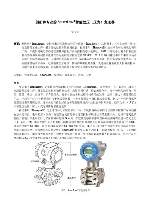
创新和专业的SmartLine®智能差压(压力)变送器李宝华摘要:变送器(Transmitter)是指输出为标准化信号的传感器(Transducer),品种繁多,其中的差压(压力)变送器是工业生产中最常见的过程参数检测仪表。
霍尼韦尔(Honeywell)是全球自动化领域的领军厂商,在提供精确可靠的过程测量和控制产品方面拥有悠久的历史,1983年率先推出复合扩散硅压阻传感器多参数测量和微处理器为基础的智能变送器ST3000,2012年10月霍尼韦尔在中国市场首发推出全新的高精准度、大量程比和高稳定性的SmartLine®智能变送器,以创新型模块化结构、专业的测量精准和稳固、电源极性任意连接、独特的效率提升性能、先进的设备集成和人机界面技术、低的产品生命周期成本,将智能变送器赋予新的定义和推向新的发展阶段。
关键词:智能变送器;SmartLine;模块化;效率提升;创新;专业引言变送器(Transmitter)是指输出为标准化信号的传感器(Transducer),品种繁多,其中的差压(压力)变送器是工业生产中最常见的过程参数检测仪表,应用范围广泛,适合测量气体、液体和蒸汽的压力、压差、流量、液位、密度等,保有量巨大。
随着工业技术和过程控制应用的发展,差压(压力)变送器经历了从上世纪五十/六十年代研发出力平衡式变送器、七十年代研发出微位移式变送器,到八十年代研发出智能型变送器的发展过程,近年来的科技创新更使智能变送器提高产品性能和长期价值、趋于完善。
(以下文中智能型差压(压力)变送器简称智能变送器。
)霍尼韦尔(Honeywell)是全球自动化领域的领军厂商,在提供精确可靠的过程测量和控制产品方面拥有悠久的历史。
电动差压(压力)变送器也是霍尼韦尔过程控制部现场仪表的主流产品,先后有过测量膜盒扭力管输出和主副杠杆力平衡机械结构的29系列、扩散硅传感器和惠斯登桥路检测并有温度补偿的全电子41系列,1983年率先推出复合扩散硅压阻传感器多参数测量和微处理器为基础的智能变送器ST 3000,包括高性能的ST 3000-100系列和基本型的ST 3000-900系列。
SmartLineTechnical InformationSTR700 SmartLine Remote Diaphragm Seals Specification 34-ST-03-124, November 2018 IntroductionPart of the SmartLine® family of products, the STR700 issuitable for monitoring, control and data acquisition.STR700 products feature piezoresistive sensor technologycombining pressure sensing with on chip temperaturecompensation capabilities providing high accuracy, stabilityand performance over a wide range of applicationpressures and temperatures.The SmartLine family is also fully tested and compliant withExperion ® PKS providing the highest level of compatibilityassurance and integration capabilities. SmartLine easilymeets the most demanding application needs for pressuremeasurement applications.Best in Class Transmitter Features:∙Accuracies up to 0.075% Span standard∙Automatic static pressure & temperature compensation∙Rangeability up to 100:1∙Easy to use and intuitive display capabilities∙Intuitive External zero, span, & configuration capability∙Comprehensive on-board diagnostic capabilities∙Integral Dual Seal design for highest safety based onANSI/NFPA 70-202 and ANSI/ISA 12.27.0∙World class overpressure protection∙Full compliance to SIL 2/3 requirements.Remote Seal/Transmitter Span & Range Limits:Model URLpsid (bar)LRLpsid (bar)Max Spanpsid (bar)Min Spanpsid (bar)STR735D 100 (7.0) -100 (-7.0) 100 (7.0) 0.9 (0.062) Model psig (bar) psig (bar) psig (bar) psig (bar) STR745G 500 (35.0) -14.7 (-1.0) 500 (35.0) 5 (0.35) Figure 1 – STR700 Remote Diaphragm Seal Unit Typical Diaphragm Seal applications∙High Process Temperatures∙Viscous or Suspended Solids∙Highly Corrosive Process Materials∙Sanitary Applications∙Applications with Hydrogen Permeation Possibilities ∙Level Applications with Maintenance Intensive Wet Legs∙Applications requiring remote Transmitter Mounting ∙Tank Applications with Density or InterfaceMeasurementsCommunications/Output Options:∙HART ® (version 7.0)DescriptionThe SmartLine family pressure transmitters are designed around a high performance piezo-resistive sensor. This one sensor actually integrates multiple sensors linking process pressure measurement with on-board static pressure (DP Models) and temperature compensation measurements.Indication/Display OptionStandard LCD Display Featureso Modular (may be added or removed in the field)o Supports HART protocol varianto0, 90,180, & 270 degree position adjustmentso Configurable (HART only) and standard (Pa, KPa, MPa, KGcm2, Torr, ATM, mH2O, bar, mbar, inH2O,inHG, FTH2O, mmH2O, mm HG, & psi) measurement units.o Supports Flow engineering unitso 2 Lines 6 digits PV (9.95H x 4.20W mm) 8 Characters o Square root output indication (√) and Write protect Indicationo Built in Basic Device Configuration through Internal Buttons – Range/Engineering Unit/Loop Test /LoopCalibration/Zero /Span SettingDiagnosticsSmartLine transmitters all offer digitally accessible diagnostics which aid in providing advanced warning of possible failure events minimizing unplanned shutdowns, providing lower overall operational costsSystem Integrationo SmartLine communications protocols all meet the most current published standards for HART.o All ST 700 units are Experion tested to provide the highest level of compatibility assurance Configuration ToolsExternal Two Button Configuration OptionSuitable for all electrical and environmental requirements, SmartLine offers the ability to configure the transmitter and display, for all basic parameters, via two externally accessible buttons when a display option isselected. Zero/span capabilities are also optionally available via two external buttons with or without selection of the display option.Internal Two Button Configuration OptionThe Standard display has two buttons that can be used for Basic configuration such as re ranging, PV Engineering unit setting, Zero/Span settings, Loop testing and calibration functions.Hand Held ConfigurationSmartLine transmitters feature two-way communication and configuration capability between the operator and the transmitter. This is accomplished via Honeywell’s field-rated Multiple Communication Configurator (MCT404).The MCT404 is capable of field configuring HART Devices and can also be ordered for use in intrinsically safe environments. All Honeywell transmitters are designed and tested for compliance with the offered communication protocols and are designed to operate with any properly validated hand held configuration device.Personal Computer ConfigurationField Device Manager (FDM) Software and FDM Express are also available for managing HART configurations.Modular DesignTo help contain maintenance & inventory costs, all ST 700 transmitters are modular in design supporting the user’s ability to replace meter bodies, standard displays or electronic modules without affecting overall performance. Each meter body is uniquely characterized to provide in-tolerance performance over a wide range of application variations in temperature and pressure.Modular Features∙Meter body replacement∙Add or remove standard displays∙Add or remove lightning protection (terminalconnection)With no performance effects, Honeywell’s unique modularity results in lower inventory needs and lower overall operating costs.Performance SpecificationsReference Accuracy(conformance to +/-3 Sigma)Accuracy at Specified Span, Temperature and Static Pressure:(conformance to +/-3 Sigma)Total Performance (% of Span):Total Performance = +/- √( Accuracy)2 + (Temp Effect)2Total Performance Examples: (5:1 Turndown, up to 50 o F shift)STR735D @ 20 psid: 1.48% of spanTypical Calibration Frequency:Calibration verification is recommended every four (4) yearsNotes:1.Terrninal Based Accuracy – Includes combined effects of linearity, hysteresis, and repeatability. Analog output adds 0.006% of span.2. For zero based spans and reference conditions of 25o C (77o F), 0 psi static pressure for DP, >= 0 psia for GP, 10 to 55% R.H, and 316Stainless Steel barrier diaphragms3. Specification applies to transmitter with 2 balanced remote seals. Apply a factor of 1.5 for temperature effect of capillary lengths greaterthan 10 feet.Operating Conditions – All ModelsParameterReferenceCondition (atzero static)Rated Condition Operative Limits Transportation andStorage︒C ︒F ︒C ︒F ︒C ︒F ︒C ︒FAmbient Temperature125±1 77±2 - - - - -55 to 90 -67 to 194 Humidity %RH10 to 55 0 to 100 0 to 100 0 to 100 Vacuum Region, MinimumPressuremmHg absolute Atmospheric (See Figure 4 for vacuum limitation)Supply Voltage, Current, and Load Resistance 10.8 to 42.4 Vdc at terminals (IS versions limited to 30 Vdc) 0 to 1,440 ohms (as shown inFigure 2)Maximum Allowable Working Pressure (MAWP)4 (ST 700 products are rated to Maximum Allowable Working Pressure. MAWP depends on Approval Agency and transmitter materials of construction.)MAWP is minimum of Body Rating or Seal Rating (See Model Selection Guide for Seal MAWP)Body MAWPSTR735D 750 psig (51.7 bar) Bolted Process HeadsSTR745G 500 psig (35 bar)1 Ambient Temperature Limit is a function of Process Interface Temperature. (See Figures 3 & 4) LCD Display operating temperature -20︒C to +70︒C . Storage temperature -30︒C to 80︒C4 Consult factory for MAWP of ST 700 transmitters with CRN approval.Figure 2 – Supply voltage and loop resistanceFigure 3- Ambient temperature LimitsFigure 4 - STR700 Remote Seals operable limits for pressure vs. temperature20040Maximum Ambient 1801601401201008060200185165Temperature (°F)140350200450Process Interface Temperature (°F)pressure limits, (equipment with safety functions in accordance with Pressure Equipment Directive 97/23/EC article 1, 2.1.3), require separate examination.Performance Conditions for the range transmitter.Table 1 – Typical Maximum capillary length and diaphragm size chartFigure 5 - STR700 transmitter with remote diaphragm seals shown mounted on a tankReference Dimensions Horizontal MountingReference Dimensions Horizontal Mounting (cont’d)Figure 6 - Approximate Horizontal Mounting Dimensions for Remote Seal Transmitter Reference Dimensions Vertical MountingReference Dimensions Vertical Mounting (cont’d)Figure 7 — Approximate vertical mounting dimensions for Remote Seal TransmitterReference Dimensions (cont’d) Flush Flanged Seal DimensionsFigure 8 - Seal Dimensions (Flush Flanged) Figure A Figure BFigure C Figure DReference Dimensions (cont’d) Flush Flanged Seal with LowerFigure 9 - Seal Dimension (Flush Flanged)Flush Flanged Seal with LowerFlush Flanged Seal with LowerNote: 0.90 dimension is 0.70 for 4.1” Dia DiaphragmReference Dimensions (cont’d)Flanged Seal with Extended DiaphragmFigure 10 — Seal Dimensions (Extended Diaphragms) Pancake SealFigure 11 — Seal Dimensions (Pancake)Seal with Threaded Process ConnectionFigure 12— Seal Dimensions (Threaded Process Connection Seals) Calibration RingFigure 13— Calibration RingCommunications Protocols & Diagnostics HART ProtocolVersion:HART 7Power SupplyVoltage: 10.8 to 42.4Vdc at terminalsLoad: Maximum 1440 ohms. See Figure 2.Minimum Load: 0 ohms. (For handheld communications a minimum load of 250 ohms is required)Standard DiagnosticsST 700 top level diagnostics are reported as either critical or non-critical and readable via the DD/DTM tools or integral display as shown below.Non-Critical DiagnosticsRefer to ST 700 manuals for additional level diagnostic information.1.Operating Parameters:Voltage= 11 to 42 V DC Current= 4-20 mA Normal2.Intrinsically Safe Entity Parametersa. Analog/ DE/ HART Entity Values:Vmax= Ui = 30V Imax= Ii= 105mA Ci = 4.2nF Li =984 uH Pi =0.9WTransmitter with Terminal Block Revision E or LaterVmax= Ui = 30V Imax= Ii= 225mA Ci = 4.2nF Li = 0 Pi =0.9WNote : Transmitter with Terminal Block Revision E or laterThe revision is on the label that is on the module. There will be two lines of text on the label:∙First is the Module Part #: 50049839-001 or 50049839-002∙Second line has the supplier information, along with the REVISION:XXXXXXX-EXXXX, THE “X” is production related, THE POSITION of the“E” IS THE REVISION.Other Certification OptionsSILMaterials- NACE MR0175, MR0103, ISO15156Application DataLiquid Level: Closed TankDetermine the minimum and maximum pressuredifferentials to be measured (Figure 14)PMin = (SGp x a) - (SGf x d)= LRV when HP at bottom of tank= –URV when LP at bottom of tankPMax = (SGp x b) - (SGf x d)= URV when HP at bottom of tank= –LRV when LP at bottom of tankWhere:minimum level at 4mAmaximum level at 20 mAa = distance between bottom tap and minimumlevelb = distance between bottom tap and maximumleveld = distance between tapsSG f = Specific Gravity of capillary fill fluid (Seepage 6“Material Spec” for values.)SG p = Specific Gravity of process fluidFigure 14—Closed tank liquid level measurement distanceApplication Data (Cont’d)Density or Interface*Calculate the minimum and maximum pressure differentials to be measured. (Figure 15)P min = (SG min– SG f) x (d);minimum density, 4mA outputP max = (SG max– SG f) x (d);maximum density, 20mA outputWhere:d = distance between the tapsSG max = maximum Specific GravitySG min = minimum Specific GravitySG f = Specific Gravity of capillary fill fluid (See page 6“Material Specifications” for values.)Figure 15- Density, direct acting transmitter configuration Seal ConfigurationsFigure 16—Flush Flange Seals and with Left LowerFlush Flange Seals can be used with differential, gauge and absolute pressure transmitters and are available with 3” ANSI Class 150, ANSI Class 300 and DIN DN80-PN40 process connections. Flush flange seals can also be provided with Lowers. Lowers are essentially calibration rings, which allow flushing connections if needed.Figure 17—Pancake SealsPancake Seals can be used with differential, gauge and absolute pressure transmitters and are available with 3” ANSI Class 150, 300 and 600 process connectionsSeal Configurations (cont’d)Figure 18 —Flange Seal with Extended DiaphragmFlange Seal with Extended Diaphragm can be used with differential, gauge and absolute pressure transmitters and are available with 3” and 4” ANSI Class 150, ANSI Class 300, DIN DN80-PN40 and DIN DN100-PN40 process connections. 2”, 4” and 6” extension lengths are available.Figure 19— Seals with Threaded ProcessConnectionsSeals with Threaded Process Connections can be used with differential, gauge and absolute pressure transmitters and are available with ½”, ¾” and 1” NPT Female process connections.Figure 20 — Calibration RingsCalibration Rings are available with Flush Flange Seals and Pancake Seals. Flushing ports (1/4” or ½”) are available with calibration rings. Figure 21 — Stainless Steel Armor and PVC Coated Stainless Steel Armor CapillariesStainless Steel Armor and PVC Coated Stainless Steel Armor Capillaries are available with Honeywell Remote Seal Solutions.Figure 22 —2” Stainless Steel Ni pples2” Stainless Steel Nipples are available for Close-Coupled remote seal solutionsFigure 23 — Welded Meter Body for All-WeldedRemote Seal SolutionWelded Meter Body for All-Welded Remote Seal Solution. The welded ST 700 meter body is an important part of an All-Welded Remote Seal Solution, which is commonly used in Vacuum applications.Model STR700(DP, GP) Remote SealsModel Selection Guide 34-ST-16-124 Issue 4Instructions● Select the desired Key Number. The arrow to the right marks the selection available. ● Make selections from each Table (I, II and IX) using the column below the proper arrow. ● A (●) denotes unrestricted availability. A letter denotes restricted availability. ● Restrictions follow Table IX. Key NumberIIIIVVVI VIIIX---_-_ _ _-_ _ _-_- -+ 0 0 0 0KEY NUMBERNote:Remote seal system pressure rating is body rating or seal rating, w hichever is less.TABLE I●●● ● ●● 22 ● 3● 3 4 22●● ● ● 55 ●● ●● ●● ●● ●● 55 ●● ●● ●● ●● ●● ●● ●● ●● ●● ●● ●● ●● 66 ●● 7711 Limited vacuum availability.12Minimum static pressure requirement. No vacuum allow ed. See Specifications 34-ST-03-88 Figure 15In-Line Gauge All weldedDual Head DP 35 feet 10.7 m_ _ _ _ _ M _2 inch long SS nipple close-coupled _ _ _ _ _ 2 _g. Seal OptionNone_ _ _ _ _ _ 0Teflon Coated Seal Diaphragm - only for anti-sticking_ _ _ _ _ _ 420 feet 6.1 m _ _ _ _ _ K _25 feet 7.5 m _ _ _ _ _ L _ 5 feet 1.5 m PVC Coated SS Armor _ _ _ _ _ G _10 feet 3.0 m _ _ _ _ _ H _15 feet 4.5 m_ _ _ _ _ J _25 feet 7.5 m _ _ _ _ _ E _35 feet 10.7 m_ _ _ _ _ F __ _ _ _ _ B _15 feet 4.5 m_ _ _ _ _ C _20 feet 6.1 m_ _ _ _ _ D _f. Connection of Remote Seal to MeterBodyNo Capillary, No Nipple (Specify for VAM Unit Only)_ _ _ _ _ 0 _Capillary Length 5 feet 1.5 m SS Armor_ _ _ _ _ A _10 feet 3.0 m Neobee ® M20 11_ _ _ _ 4 _ _Syltherm ® 80012_ _ _ _ 5 _ __ _ _ N _ _ _e. Secondary Fill Fluid (capillary &seal)No Fill Fluid _ _ _ _ 0 _ _Silicone Oil 200_ _ _ _ 1 _ _Fluorinated Oil CTFE _ _ _ _ 2 _ _Silicone Oil 704_ _ _ _ 3 _ _316 SS with all-welded meter body_ _ E _ _ _ _d. Bolts andNutsforTransmitterHeads None_ _ _ 0 _ _ _Carbon Steel Bolts and Nuts _ _ _ C _ _ _316 SS Bolts and Nuts_ _ _ S _ _ _A286 SS (NACE) Bolts and 304 SS (NACE) NutsIn-Line Gauge 316 SS Bonnet_ _ A _ _ _ _316 SS Bonnet for Close-Couple_ _ B _ _ _ _Dual Head DP 316 SS (bolt-on heads)_ _ C _ _ _ _316 SS for Close-Couple_ _ D _ _ _ _b. Primary FillFluid (Meter body)Silicone Oil200_ 1 _ _ _ _ _Fluorinated Oil CTFE_ 2 _ _ _ _ _c. Construction Non-Wetted Adapter Head MaterialsDescriptionSelection Meter Body & Capillariesa. Number ofSeals 1 Remote Seal (High Side)1 _ _ _ _ _ _2 Remote Seals2 _ _ _ _ _ _1 Remote Seal (Low Side)3 _ _ _ _ _ _STR735D 500 (35)-14.7 (-1.0)500 (35)5 (0.35)psi (bar)STR745GMeasurement Range Std Accuracy100 (7) -100 (-7)100 (7)0.9 (0.062)psi (bar)URL LRL Max Span Min Span Units Selection AvailabilityIIIVIIISTR7 _ _ __ _ _ _ _ _ __ _ _ _ _ _ _ _ _ _ _ _ _ _ _ , _ _Model Selection GuideModel Selection Guides are subject to change and are inserted into the specifications as guidance only.STR745G STR735DNote:When selecting required seal, you must specify only the 9 selections within the required seal type.TABLE II2121AFA _ _ _ _ _ _●●AFC _ _ _ _ _ _●●AFM _ _ _ _ _ _●●_ _ _ AA _ _ _ _●●_ _ _ AB _ _ _ _●●_ _ _ AC _ _ _ _●●_ _ _ AE _ _ _ _88_ _ _ AF _ _ _ _88_ _ _ _ _ 1 _ _ _●●_ _ _ _ _ 2 _ _ _●●_ _ _ _ _ _ 1 _ _●●_ _ _ _ _ _ 2 _ _99_ _ _ _ _ _ _ A _●●_ _ _ _ _ _ _ B _1010_ _ _ _ _ _ _ C _1010_ _ _ _ _ _ _ D _1010_ _ _ _ _ _ _ _ 0●●_ _ _ _ _ _ _ _ H 1111_ _ _ _ _ _ _ _ J 1111(Metal plug material _ _ _ _ _ _ _ _ M 1111w ill be the same as _ _ _ _ _ _ _ _ N 1111Cal. ring material if _ _ _ _ _ _ _ _ P 1111metal plug is chosen )_ _ _ _ _ _ _ _ Q 1111_ _ _ _ _ _ _ _ R 1111_ _ _ _ _ _ _ _ S1111Table II continued next page1 Standard facing 125-250 AARH RF (raised face) serrated surface finish.4P lastic P lugs are TE MP ORARY ONLY to protect threads and MUST be RE MOVE D before installation 5Tantalum Upper insert has Tantalum w etted parts and 316 SS or CS non-w etted parts Note: Remote seal system pressure rating is body rating or seal rating, w hichever is less.SelectionFlush FlangedSeal3.5"3"ANSI Class 150ANSI Class 30080mmDescriptionSealsNo Seal Attached to Core Transmitter (Specify for VAM Unit Only)0 0 0 0 0 0 0 0 0Seal TypeDia phra gm Dia me te rFlange SizeFlange PressureRating 1SelectionDIN DN80-PN40Monel 400®Monel 400®Tantalum 5316L SSNon-Wetted Material(upper)CS (Nickel Plated)316L SSWetted MaterialDiaphragmUpper InsertSelection316L SS316L SS Hastelloy ® C-276316L SS Hastelloy ® C-276Hastelloy ® C-276Flushing NoneConnections One 1/4" with plastic plug and Plugs4One 1/4" with metal plug Two 1/4" with plastic plugs Two 1/4" with metal plugs Seal-Capillary Connection Center Seal Side Seal Calibration RingsNone 316L SS Hastelloy ® C-276Monel 400®One 1/2" with plastic plug One 1/2" with metal plug Two 1/2" with plastic plugs Two 1/2" with metal plugsSTR745GSTR735DTABLE IIDescriptonANSI 15022BCA _ _ _ _ _ _●●ANSI 30022BCC _ _ _ _ _ _●●ANSI 15022BGA _ _ _ _ _ _●●ANSI 30022BGC _ _ _ _ _ _●●ANSI 15022BDA _ _ _ _ _ _●●ANSI 30022BDC _ _ _ _ _ _●●ANSI 15022BFA _ _ _ _ _ _●●ANSI 30022BFC _ _ _ _ _ _●●1/2"ANSI 15023CAA _ _ _ _ _ _●●ANSI 15023CCA _ _ _ _ _ _●●ANSI 30023CCC _ _ _ _ _ _●●ANSI 15022CGA _ _ _ _ _ _●●ANSI 30022CGC _ _ _ _ _ _●●ANSI 15022CDA _ _ _ _ _ _●●ANSI 30022CDC _ _ _ _ _ _●●1/2"ANSI 15022DAA _ _ _ _ _ _●●ANSI 15023DCA _ _ _ _ _ _●●ANSI 30023DCC _ _ _ _ _ _●●ANSI 15023DGA _ _ _ _ _ _●●ANSI 30023DGC _ _ _ _ _ _●●ANSI 15023DDA _ _ _ _ _ _●●ANSI 30022DDC _ _ _ _ _ _●●ANSI 15022DFA _ _ _ _ _ _●●ANSI 30022DFC _ _ _ _ _ _●●DiaphragmLow er_ _ _ BA _ _ _ _●●_ _ _ BB _ _ _ _●●_ _ _ BC _ _ _ _●●_ _ _ BE _ _ _ _88_ _ _ BF _ _ _ _88_ _ _ BG _ _ _ _88_ _ _ BH _ _ _ _1313UpperUpper Insert_ _ _ _ _ 4 _ _ _●●_ _ _ _ _ 5 _ _ _●●_ _ _ _ _ _ 0 _ _●●_ _ _ _ _ _ _ 0 _●●_ _ _ _ _ _ _ H _●●_ _ _ _ _ _ _ J _●●(Metal plug material _ _ _ _ _ _ _ M _●●w ill be the same as _ _ _ _ _ _ _ N _●●Low er material, if _ _ _ _ _ _ _ P _●●metal plug is chosen -_ _ _ _ _ _ _ Q _●●(SS P lug for CS Low er _ _ _ _ _ _ _ R _●●and Tantalum Clad)_ _ _ _ _ _ _ S _●●_ _ _ _ _ _ _ _ G ● ● _ _ _ _ _ _ _ _ T ●●_ _ _ _ _ _ _ _ L1515Table II continued next page1 Standard facing 125-250 AARH RF (raised face) serrated surface finish.6Bolt material w ill be same as Upper Material. How ever, if Table I bolts/nuts material is NACE , seal bolt material w ill be 304 SS NACE.4P lastic P lugs are TE MP ORARY ONLY to protect threads and MUST be RE MOVE D before installation Note: Remote seal system pressure rating is body rating or seal rating, w hichever is less.Construction - See Spec. Figure 34-ST-03-104Seals (continued)Seal TypeDia phra gm Dia me te rFlange SizeFlange Pressure Rating 1Const. - See Spec. Figure 34-ST-03-104Flush FlangedSeal with Lower2.4"1"2"Selection316L SS316L SSHastelloy ® C-276316L SSHastelloy ®C-276Hastelloy ® C-2764.1"1"1-1/2"2"3"1-1/2"2"3"2.9"1"1-1/2"Bolts 6No SelectionFlushing NoneConnections One 1/4" with plastic plug TantalumTantalum CladNon-Wetted Material (upper, upper insert)Selection 316L SS 316L SS Carbon Steel 316L SSMonel 400®Monel 400®Tantalum 316L SSTantalum Hastelloy ® C-276Wetted MaterialSelection (non-asbestos)Grafoil ®Teflon ®Gylon ® 3510GasketKlinger ®C-4401_ _ _ _ _ _ _ _ K ●●and Plugs4One 1/4" with metal plug Two 1/4" with plastic plugs Two 1/4" with metal plugs One 1/2" with plastic plug One 1/2" with metal plug Two 1/2" with plastic plugs Two 1/2" with metal plugsSTR745G STR735DTABLE IIDescripton3"EFA _ _ _ _ _ _●●(2.8" OD EFC _ _ _ _ _ _●●extension)EFM _ _ _ _ _ _●●4"FGA _ _ _ _ _ _●●(3.70" OD FGC _ _ _ _ _ _●●extensionFGP _ _ _ _ _ _●●DiaphragmE xt. Tube_ _ _ EA _ _ _ _●●_ _ _ EB _ _ _ _●●_ _ _ EC _ _ _ _●●_ _ _ _ _ 7 _ _ _●●_ _ _ _ _ 8 _ _ _●●_ _ _ _ _ _ 0 _ _●●_ _ _ _ _ _ _ 2 _●●_ _ _ _ _ _ _ 4 _●●_ _ _ _ _ _ _ 6 _●●_ _ _ _ _ _ _ _ 0●●Table II continued belowSTR745G STR735DTABLE IIDescripton3.5"3"GFA _ _ _ _ _ _●●DiaphragmBody_ _ _ GA _ _ _ _●●_ _ _ GB _ _ _ _●●_ _ _ GC _ _ _ _●●_ _ _ GE _ _ _ _88_ _ _ GG _ _ _ _88_ _ _ _ _ _ 0 _ _●●_ _ _ _ _ _ _ A _●●_ _ _ _ _ _ _ B _1010_ _ _ _ _ _ _ C _1010_ _ _ _ _ _ _ D _1010_ _ _ _ _ _ _ _ 0●●_ _ _ _ _ _ _ _ H 1111_ _ _ _ _ _ _ _ J 1111_ _ _ _ _ _ _ _ M 1111_ _ _ _ _ _ _ _ N 1111_ _ _ _ _ _ _ _ P 1111_ _ _ _ _ _ _ _ Q 1111_ _ _ _ _ _ _ _ R 1111_ _ _ _ _ _ _ _ S1111Table II continued next page1 Standard facing 125-250 AARH RF (raised face) serrated surface finish.4P lastic P lugs are TE MP ORARY ONLY to protect threads and MUST be RE MOVE D before installation 7Tantalum Body has Tantalum w etted parts and 316 SS non-w etted partsNote: Remote seal system pressure rating is body rating or seal rating, w hichever is less.and Plugs4One 1/4" with metal plug (Metal plug material Two 1/4" with plastic plugs w ill be the same as Two 1/4" with metal plugs Calibration RingsNone 316L SS Hastelloy ®C-276Monel 400®Flushing NoneTwo 1/2" with metal plugsCal. Ring material, if One 1/2" with plastic plug metal plug is chosen )One 1/2" with metal plug Two 1/2" with plastic plugs ●BoltsNo SelectionTantalumTantalum7Non-Wetted MaterialNo Selection _ _ _ _ _ 0 _ _ _●Wetted Material316L SS316L SS Hastelloy ®C-276316L SS Hastelloy ® C-276Hastelloy ® C-276Monel 400®Monel 400®Seals (continued)Seal TypeDia phra gm Dia me te rFlange SizeFlange Pressure RatingDependent on Customer Flange1Pancake SealANSI Class 150/300/600Extension Length2"4"6"Connections One 1/4" with plastic plug SelectionNo Selection No SelectionNo SelectionSeals (continued)Seal TypeD iaphragm D iameterFlange SizeFlange Pressure Rating 1SelectionANSI Class 300DIN DN80-PN403.5"ANSI Class 150Non-Wetted CS (Nickel Plated)Material (flange)316L SS Bolts No SelectionANSI Class 300DIN DN100-PN40Wetted Material Selection 316L SS 316L SSHastelloy ® C-276316L SSFlange Seal with Extended Diaphragm2.8"ANSI Class 150Hastelloy ®C-276Hastelloy ® C-276STR745GTABLE IIDescriptonSTR735D1/2 NPT JJG _ _ _ _ _ _●●3/4 NPT JKG _ _ _ _ _ _●●1 NPT JLG _ _ _ _ _ _●●1/2 NPT KJG _ _ _ _ _ _●●3/4 NPT KKG _ _ _ _ _ _●●1 NPT KLG _ _ _ _ _ _●●1/2 NPT LJG _ _ _ _ _ _●●3/4 NPT LKG _ _ _ _ _ _●●1 NPTLLG _ _ _ _ _ _●●_ _ _ JA _ _ _ _●●_ _ _ JB _ _ _ _●●_ _ _ JC _ _ _ _●●_ _ _ JD _ _ _ _●●_ _ _ JE _ _ _ _88_ _ _ JF _ _ _ _88_ _ _ JG _ _ _ _88_ _ _ _ _ A _ _ _●●_ _ _ _ _ C _ _ _1717_ _ _ _ _ _ C _ _●●_ _ _ _ _ _ D _ _●●_ _ _ _ _ _ _ 0 _●●_ _ _ _ _ _ _ H _●●_ _ _ _ _ _ _ J _●●_ _ _ _ _ _ _ M _●●_ _ _ _ _ _ _ N _●●_ _ _ _ _ _ _ P _1818_ _ _ _ _ _ _ Q _1818_ _ _ _ _ _ _ R _1818_ _ _ _ _ _ _ S _1818_ _ _ _ _ _ _ _ G ● ● _ _ _ _ _ _ _ _ T ● ● _ _ _ _ _ _ _ _ L1515Table II continued next page4 P lastic P lugs are TE MP ORARY ONLY to protect threads and MUST be RE MOVE D before installation8If Table I Bolts and Nuts material option is NACE , Bolts and Nuts w ill ship w ith Alloy Steel NACE and MAWP may change.Note: Remote seal system pressure rating is body rating or seal rating, w hichever is less.and Plugs 4One 1/4" with metal plug (Metal plug material Two 1/4" with plastic plugs _ _ _ _ _ _ _ _ K ●●(SS P lug for CS Low erTwo 1/2" with plastic plugs and Tantalum Clad)Two 1/2" with metal plugs GasketKlinger ®C-4401 (non-asbestos)Grafoil ®Teflon ®316L SSHastelloy ® C-276Hastelloy ® C-276Monel 400®Monel 400®750 psiDiaphragmLow erSelection 316L SS Carbon Steel 316L SS316L SS Hastelloy ® C-276Bolts 8Carbon Steel 304 SS Gylon ® 3510w ill be the same as Two 1/4" with metal plugs One 1/2" with plastic plug metal plug is chosen -Selection Tantalum 316L SSWetted MaterialTantalumHastelloy ® C-276One 1/2" with metal plug 2.9"2,500 psi 1,250 psi 4.1"Seals (continued)Seal TypeDia phra gm Dia me te rThreaded ProcessConnection Size (NPT Female)Pressure Rating CS Bolts304 SSBoltsSeal with Threaded Process Connection2.4"2,500 psi 1,250 psi Flushing NoneConnections One 1/4" with plastic plug Low er material, if 1,500 psiNon-Wetted Material(upper)CS (Nickel Plated)316 Stainless Steel3 NAMUR Output Limits 3.8 - 20.5mAdc can be configured by the customer or select custom configuration Table VcSTR745G ArraySTR735DFM Approvals SM is a service mark of FM GlobalHastelloy® is a registered trademark of Haynes InternationalMonel 400® is a registered trademark of Special Metals Corporation.HART® is a registered trademark of HART Communication Foundation. Teflon® is a registered trademark of DuP ont.Neobee® is a registered trademark of Stepan Company.Syltherm® 800 is a Trademark of Dow Corning CorporationKlinger® C-4401 is a registered trademark of THE RMOSE AL, INC GRAFOIL® is a registered trademarks of GrafTech International Holdings Inc Gylon® 3510 is registered trademark of Garlock Sealing Technologies。
霍尼韦尔(honeywell)美国霍尼韦尔(honeywell)ST3000/900系列全智能变送器*Honeywell- HoneywellST3000 系列变送器(备有现货,优势价格,项目协作)差压型号:STD924 STD930 STD974 STD904微差压:STD120 STD110 STD130 STD170 STD125压力型号:STG944,STG974 ,STG94L ,STG97L,STG98L ,STG99L单法兰:STF924 STF932 STF92F STF93F双法兰:STR93D STR94G霍尼韦尔绝压型号:STA922 STA940 STA92L STA94L温度变送器:STT171 STT173 STT250SFC智能手操器STS103-001-00006-24常用型号: 霍尼韦尔差压变送器的型号有以下等:STD924-A1A-00000-MB,SM,1C (0-100KPa)STD924-E1A-00000-AN,MB,SM,1C (0-100KPa)STD924-E1H-00000-MB,S2,SM,1C (0-100KPa)STD930-A1A-00000-MB,SM,1C (0-700KPa)STD930-E1A-00000-MB,SM,1C (0-700KPa)STD930-E1H-00000-S2,MB,SM,1C (0-700KPa)STD924霍尼韦尔差压变送器 霍尼韦尔压力变送器 ST3000STD930STG944/974 霍尼韦尔压力变送器STG944(0~140 至 0~3500kPa)STG974(0~2.1 至 0~21MPa)常用型号: 霍尼韦尔压力变送器的型号有以下等:STG944-A1A-00000-SM,MB,1C (0~140 至 0~3500kPa)STG944-E1A-00000-SM,MB,1C (0~140 至 0~3500kPa)STG944-E1G-00000-S2,SM,MB,1C (0~140 至 0~3500kPa)STG944-A1G-00000-S2,SM,MB,1C (0~140 至 0~3500kPa)STG974-A1A-00000-SM,MB,1C (0~2.1 至 0~21MPa)STG974-E1A-00000-SM,MB,1C (0~2.1 至 0~21MPa)1)4~20mA标准的制定者,全球第一台智能变送器的提供者2)真正的全量程精度达到0.075%,而非其它厂家标称的参考精度0.075%;这一点得益于霍尼韦尔所独有的复合传感器技术;3)最小的耐静压值为21Mpa(STD110与远传法兰除外);4)任何一台霍尼韦尔变送器均可满足最严格的防爆要求,防爆要求不需另加价;5)负载能力高达1440欧姆……Honeywell压力变送器ST3000系列包含了差压,绝压,表压,微差压,远传法兰,和液位变送器一系列完整的产品。
ST 3000 Smart TransmitterSeries 100 High Temperature GP ModelsSTG14T, STF14T 0-500 psig / 0-35 barg34-ST-03-707/04Specification and Model SelectionGuideIn 1983, Honeywell introduced the first Smart Pressure Transmitter ― the ST 3000®. In 1989, Honeywell launched for smart field devices. Today, Honey-well transmitters demonstrate proven reliability in hundreds on installations in a wide variety of industries and applica-tions. For applications requiring direct connection to processes requiring small flange, small sanitary connec-tions or 1/2” NPT, Honeywell offers the STG14T transmitter. Applications in-clude gauge pressure for reaction ves-sels in the chemical industry as well as level applications in both the chemical and hydrocarbon processing industries with a relatively high process tempera-ture of 302F (150C). Applications for the food and pharmaceutical industries typically use sanitary connections and M-20 fill fluid.All ST 3000 transmitters can provide a 4-20 mA output, Honeywell Digitally Enhanced (DE) output, HART * output, or F OUNDATION ™ Fieldbus output. When digitally integrated with Honey-well’s Process Knowledge System™, EXPERION PKS™, ST 3000 instru-ments provide a more accurate proc-ess variable as well as advanced diag-nostics.S100 transmitters lead the industry in: • Accuracy • Stability • Reliability • Rangeability • WarrantyIncludes Lifetime Tranmsitters: • Accuracy = +/-0.0375%• Stability = +/-0.01% per year • Reliability = 470 years MTBF • Rangeability = 400 to 1• Lifetime Warranty = 15 yearsFigure 1—Series 100 High Temperature GP Transmitters feature proven pie-zoresistive sensor technology.The devices provide comprehensive self-diagnostics to help users maintain high uptime, meet regulatory requirements, and attain high quality standards. S100 transmitters are ideal for critical applications, such as custody transfer of natural gas and energy and material bal-ances, where accuracy and stability are of the utmost importance."Our commitment to Honeywell field instruments is based on seam-less integration with our Honeywell system and the enhanced fault detection that the Honeywell DE protocol offers. Honeywell instru-ments also offer us a better way of ensuring database integrity over simple analog instruments. In addition, Honeywell's high-quality sup-port has enabled us to better implement solutions to some of ourmore difficult problems. We have used Honeywell differential pressure smart transmitters for the past eight years. Based on their accuracy and low failure rates, we are now targeting critical flow applications that require the robustness that these transmitters bring.” DCS Systems EngineerInternational Integrated Oil CompanyIntroduction34-ST-03-70 Page 2Description FeaturesThe ST 3000 transmitter can replace any 4 to 20 mA output transmitter in use today and operates over a standard two-wire system.The measuring means is a piezoresistive sensor, which actually contains three sensors in one. It contains a differential pressure sensor, a temperature sensor, and a static pressure sensor.Microprocessor-based electronics provide higher span-turndown ratio, improved temperature and pressure compensation, and improved accu-racy.The transmitter’s meter body and electronics housing resist shock, vibra-tion, corrosion, and moisture. The electronics housing contains a com-partment for the single-board electronics, which is isolated from an inte-gral junction box. The single-board electronics is replaceable and inter-changeable with any other ST 3000 Series 100 or Series 900 model transmitter.Like other Honeywell transmitters, the ST 3000 features two-way com-munication between the operator and the transmitter through our Smart Field Configurator (SFC). You can connect the SFC anywhere that you can access the transmitter signal lines.The SCT 3000 Smartline® Configuration Toolkit provides an easy way to configure instruments using a personal computer. The toolkit enables configuration of devices before shipping or installation. The SCT 3000 can operate in the offline mode to configure an unlimited number of de-vices. The database can then be loaded downline during commissioning. • Choice of linear or square root output conformity is asimple configuration selec-tion.• Direct digital integration with Experion PKS and other con-trol systems provides localmeasurement accuracy to thesystem level without addingtypical A/D and D/A converterinaccuracies.• Unique piezoresistive sensor automatically compensatesinput for temperature andstatic pressure.Added “smart”features include configuringlower and upper range val-ues, simulating accurate ana-log output, and selecting pre-programmed engineeringunits for display.• Smart transmitter capabilities with local or remote interfac-ing means significant man-power efficiency improve-ments in commissioning,start-up, and ongoing mainte-nance functions.34-ST-03-70 Page 334-ST-03-70 Page 4Specifications34-ST-03-70Page 5Ambient Temperature De-ratingSilicone Fill Fluid Neobee Fill FluidProcess temperatures above 125 °C (257 °F) require de-rating the ambient limit as follows:Process temperatures above 85 °C (185 °F) require de-rating the ambient limit as follows:Process Temperature Ambient TemperatureLimit Process Temperature Ambient TemperatureLimit150 °C (302 °F) 140 °C (284 °F) 125 °C (257 °F)50 °C (122 °F)60 °C (140 °F)85 °C (185 °F)110 °C (230 °F)100 °C (212 °F)85 °C (185 °F)50 °C (122 °F)60 °C (140 °F)75 °C (167 °F)Performance Under Rated Conditions* -* Performance specifications are based on reference conditions of 25°C (77°F), 10 to 55% RH, and 316L SS diaphragm. ** Transmitter URL limit or maximum process connection rating, whichever is lower.34-ST-03-70Page 6Performance Under Rated Conditions – General for all ModelsParameter Description Output (two-wire) Analog 4 to 20 mA or digital communications DE mode. Options available forF OUNDATION Fieldbus and HART protocol.Supply Voltage Effect ±0.005% span per volt.Damping Time Constant Adjustable from 0 to 32 seconds digital damping.EMC Classification Group 1, Class A, ISM Equipment (EN 55011, emissions), Industrial Equipment (EN50082-2, immunity)CE Conformity (Europe) 89/336/EEC, Electromagnetic Compatibility (EMC) Directive.Lightning Protection Option (Code “LP”) Leakage Current: ***********************,93°CImpulse Rating: 10/20 µ sec. 5,000 Amps (50 strikes) 10,000 Amps (20 strikes) (rise/decay) 10/1000 µ sec. 250 Amps (1000 strikes) 500 Amps (400 strikes)Physical and Approval BodiesParameter Description Process Interface See Model Selection Guide for Material Options for desired process connection.Diaphragm Materials (wetted) 316L Stainless SteelGasket Ring Materials (wetted) 316L Stainless SteelMounting Flange (non-wetted) 316 Stainless Steel.Fill Fluid Silicone (DC 200) or Neobee (M20)Electronic Housing Epoxy-Polyester hybrid paint. Low copper-aluminum alloy. Meets NEMA type 4X(watertight) and designed to meet NEMA 7 (explosion proof).Process Connections Process Head: 1/2-inch NPT.Sanitary: 2” Sanitary Tri-Clamp.Flange: 1/2”, 1”, 1 1/2” and 2” 150# or 300# ANSI flange.Wiring Accepts up to 16 AWG (1.5 mm diameter).Mounting 1/2-inch NPT, sanitary seal, or flange mount connection.Dimensions See Figures 4 to 6Net Weight 7 pounds (3.2 Kg) to 15 pounds (7 Kg)Approval Bodies- Hazardous Areas- Canadian RegistrationNumber (CRN) Approved as explosion proof and intrinsically safe for use in Class I, Division 1, Groups A, B, C, D locations, and nonincendive for Class I, Division 2, Groups A, B, C, D locations. Approved EEx ia IIC T4, T5, T6 and EEx d IIC T5, T6 per ATEX standards. See attached Model Selection Guide for options.- All ST 3000 model designs, except STG19L, STG99L, STG170, STG180, have been registered in all provinces and territories in Canada and are marked CRN: 0F8914.5C.Table continued on next page ⇒34-ST-03-70Page 7Physical and Approval Bodies, continuedParameter DescriptionPressure Equipment Directive (97/23/EC) The ST 3000 pressure transmitters listed in this Specification have no pressurized internal volume or have a pressurized internal volume rated less than 1,000 bar (14,500 psig) and/or have a maximum volume of less than 0.1 liter. Therefore, these transmitters are either; not subject to the essential requirements of the directive97/23/EC (PED, Annex 1) and shall not have the CE mark, or the manufacturer has the free choice of a module when the CE mark is required for pressures > 200 bar (2,900 psig).NOTE: Pressure transmitters that are part of safety equipment for the protection of piping (systems) or vessel(s) from exceeding allowable pressure limits, (equipment with safety functions in accordance with Pressure Equipment Directive 97/23/EC article 1, 2.1.3), require separate examination.Figure 4 Typical mounting dimensions for 1/2-inch NPT connection models for reference.34-ST-03-70 Page 8Figure 5 Typical mounting dimensions for flush sanitary seal connection models for reference.34-ST-03-70Page 9Figure 6 Typical mounting dimensions for small flange connection models for reference.34-ST-03-70 Page 10Options Ordering Information Indicating Meter(ME and SM Options)Two integral meter options are available. An analog meter (option ME) is available with a 0 to 100% linear scale. The Smart Meter (option SM) provides an LCD display for both analog and digital output and can be configured to display pressure in pre-selected engineering units.Lightning Protection (Option LP)A terminal block is available with circuitry that protects the transmitter from transient surges induced by nearby lightning strikes.HART Protocol Compatibility (Option HC)An optional electronics module is available for the ST 3000 that provides HART Protocol compatibility. Transmitters with the HART Option are compatible with the AMS System. (Contact your AMS Supplier if an upgrade is required.)Transmitter Configuration (Option TC)The factory can configure the transmitter linear/square root extraction, damping time, LRV, URV and mode (analog/digital) and enter an ID tag of up to eight characters and scratchpad information as specified. Lifetime Warranty(Option WL)Extends limited 1-year warranty policy to 15 years for ST 3000S100 pressure transmitters. See Honeywell Terms and Conditions.Indicator Configuration(Option CI)Provides custom configuration ofSmart MetersTagging (Option TG)Up to 30 characters can be addedon the stainless steel nameplatemounted on the transmitter’selectronics housing at no extra cost.Note that a separate nameplate onthe meter body contains the serialnumber and body-related data. Astainless steel wired on tag withadditional data of up to 4 lines of 28characters is also available. Thenumber of characters for taggingincludes spaces.Custom Calibration and ID inMemory (Option CC)The factory can calibrate any rangewithin the scope of the transmitter’srange and enter an ID tag of up toeight characters in the transmitter’smemory.F OUNDATION Fieldbus(Option FF)Equips transmitter with FF protocolfor use in 31.25 kbit/s FF networks.See document 34-ST-03-72 foradditional information on ST 3000Fieldbus transmitters.Contact your nearest Honeywell sales office,orIn the U.S.:HoneywellIndustrial Automation & Control16404 North Black Canyon Hwy.Phoenix, AZ 850531-800-288-7491In Canada:The Honeywell Centre155 Gordon Baker Rd.North York, Ontario M2H 3N71-800-461-0013In Latin America:Honeywell Inc.480 Sawgrass Corporate Parkway,Suite 200Sunrise, FL 33325(954) 845-2600In Europe and Africa:Honeywell S. A.Avenue du Bourget 11140 Brussels, BelgiumIn Eastern Europe:Honeywell Praha,s.r.o. Budejovicka 1140 21 Prague 4,Czech RepublicIn the Middle East:Honeywell Middle East Ltd.Khalifa Street,Sheikh Faisal BuildingAbu Dhabi, U. A. E.In Asia:Honeywell Asia Pacific Inc.Honeywell Building,17 Changi Business Park Central 1Singapore 486073Republic of SingaporeIn the Pacific:Honeywell Pty Ltd.5 Thomas Holt DriveNorth Ryde NSW Australia 2113(61 2) 9353 7000In Japan:Honeywell K.K.14-6 Shibaura 1-chromeMinato-ku, Tokyo, Japan 105-0023Specifications are subject to change without notice Or, visit Honeywell on the World WideWeb at: 34-ST-16-47 Issue 14**The user must determine the type of protection required for installation of the equipment. The user shall then check the box [D] adjacent to the type of protection used on the equipment certification nameplate. Once a type of protection has been checked on the nameplate, the equipment shall not then be reinstalled using any of the other certification types.This Page Intentionally BlankST 3000 is a registered trademark of Honeywell International Inc.HART* is a trademark of the Hart Communication Foundation.FOUNDATION™ is a trademark of the Fieldbus Foundation.Industrial Measurement and ControlHoneywell International Inc.2500 W. Union Hill Drive,Phoenix, Arizona 85027 Honeywell International Inc.。
SmartLineIntroductionPart of the SmartLine® family of products, the SmartLine STT700 is a high performance temperature transmitter offering high accuracy and stability over a wide range of process and ambient temperatures. SmartLine easily meets the most demanding needs for temperature measurement applications.Best in Class Features: The STT700 is single or a dual input temperature transmitter that supports millivolt, thermocouple and RTD sensors. It is available with either HART or DE protocol output. High performanceo Digital accuracy up to 0.15 Deg C for Pt100 o Stability up to ±0.05% of URL per year for ten yearso500 mSec update time (single input) o 1 Sec update time (dual input) Reliable measurementoBuilt in galvanic isolationo Sensor break detectiono Comprehensive on-board diagnostic capabilities oFull compliance to SIL 2/3 requirements. o Available with 4 year warrantyo Supports Namur 89 Wire breakoDirect entry of Callendar-van Dusen coefficients R 0, α, δ and β for calibrated RTD sensors . Lower Cost of Ownershipo Universal inputo Dual sensor optiono Polarity insensitive loop wiringMounting Options:o Direct sensor head mounting in DIN Form A aluminum housing.oOther mounting options available include wall, pipe, DIN Rail or single compartment field housingFigure 1 –SmartLine STT700 Temperature Transmitter.Top image shown with housing.Bottom image with (HART) module only shownwith dual input capability.Communications/Output Options:o 4-20 mA DC o HART ® (version 7.0)oHoneywell Digitally Enhanced (DE)All transmitters are available with the above listed output and communications protocol option.DescriptionPart of the SmartLine® family of products, the SmartLine STT700 is a high performance temperature transmitter offeringhigh accuracy and stability over a wide range of process and ambient temperatures. The STT700 addresses the broadest market applications by providing a temperature transmitter that can meet the bulk of the industrial application needs. TheSTT700’s versatility, including the ability to select single or dual input, HART or DE protocol, with or without display, various mounting configurations, and the ability to connect to 2, 3 or 4-wire sensor types, allows your site to standardize on a single product and thus simplifying support and training.Indication/Display OptionThe STT700 accommodates a Standard alphanumeric LCD display.Standard LCD Display Featureso Modular (may be added or removed in the field)o0, 90, 180 & 270 degree position adjustmentso Deg C, F, R and Kelvin measurement unitso 2 Lines 6 digits PV (9.95H x 4.20W mm), 8 Characterso Built in Basic Device Configuration through internal buttons – Range/Engineering Unit/Loop Test/ Loop Calibration/Zero-Span Settingo Write Protect indicationConfiguration ToolsHand Held ConfigurationSmartLine transmitters feature two-way communication and configuration capability between the operator and the transmitter. This is accomplished via Honeywell’s field-rated Multiple Communication Configuration tool. The Honeywell handheld MC Toolkit is capable of field configuring HART and DE devices and can also be ordered for use in intrinsically safe environments. All Honeywell transmitters are designed and tested for compliance with the offered communication protocols and are designed to operate with any properly validated handheld configuration device.Personal Computer ConfigurationHART Communicator Model 375, 475 or MC Toolkit for HART 7 Models.Field Device Manager (FDM) Software and FDM Express are also available for managing HART and DE device configurations (FDC).Smart Field Communicator (SFC) for DE Models.DiagnosticsSmartLine transmitters all offer digitally accessible diagnostics which aid in providing advanced warning of possible failure events minimizing unplanned shutdowns, providing lower overall operational costs.System Integrationo All SmartLine products communications protocols meet all of the most current published standards for HARTo SmartLine STT700 is fully compatible with Honeywell’s DE protocol.STT250 CompatibilityThe STT700 design allows it to easily replace an existing STT250 Temperature Transmitter. The STT700 physically fits into an existing STT250 mount and the STT700 offers the same functions as a STT250.Performance Specifications1,3Reference Accuracy 2 (conformance to +/-3 Sigma)Input Type Maximum Range Limits DigitalAccuracy(+/-)Output D/AAccuracy(% of span)StandardsRTD(2,3,4 wire)° C° F ° C %Pt100 (α=0.00385) -200 to 450 -328 to 842-200 to 850 -328 to 15620.150.250.025 IEC751:1990Pt200 (α=0.00385) -200 to 450 -328 to 842-200 to 850 -328 to 15620.300.400.025 IEC751:1990Ni 1205(α=0.00672)-80 to 260 -112 to 500 0.12 0.025 Edison Curve #7Pt505 (α=0.00391) -200 to 450 -328 to 842-200 to 600 -328 to 11120.320.550.025 GOST 6651-94Pt1005 (α=0.00391) -200 to 450 -328 to 842-200 to 600 -328 to 11120.160.270.025 GOST 6651-94Cu 505 (α=0.00426)-50 to 200 -58 to 392 0.42 0.025 GOST 6651-94 Cu 1005 (α=0.00426)-50 to 200 -58 to 392 0.50 0.025 GOST 6651-94 Cu 505 (α=0.00428)-200 to 200 -328 to 392 0.55 0.025 GOST 6651-94 Cu 1005 (α=0.00428)-200 to 200 -328 to 392 0.32 0.025 GOST 6651-94 Thermocouples ° C° F° C %B 550 to 1820 1022 to 3308200 to 1820 392 to 33081.003.000.025 ANSI / ASTM E-230 (ITS-90)C50 to 1650 32 to 30020 to 2300 32 to 41721.201.700.025 ANSI / ASTM E-230 (ITS-90)E 0 to 1000 32 to 1832-200 to 1000 -328 to 18320.300.600.025 ANSI / ASTM E-230 (ITS-90)J0 to 800 32 to 1472-200 to 1200 -200 to 21920.300.700.025 ANSI / ASTM E-230 (ITS-90)K -120 to 1370 -191 to 2498-200 to 1370 -328 to 24980.600.900.025 ANSI / ASTM E-230 (ITS-90)N 0 to 1300 32 to 2372-200 to 1300 -328 to 23720.401.500.025 ANSI / ASTM E-230 (ITS-90)R 500 to 1760 -58 to 3200-50 to 1760 -58 to 32000.601.000.025 ANSI / ASTM E-230 (ITS-90)S 500 to 1760 -58 to 3200-50 to 1760 -58 to 32000.601.000.025 ANSI / ASTM E-230 (ITS-90)T -100 to 400 -148 to 752-250 to 400 -418 to 7520.300.500.025 ANSI / ASTM E-230 (ITS-90)L5-0 to 800 -32 to 1472-200 to 800 -328 to 14720.500.900.025 GOST R 8.585-20014 STT700 Smart Temperature1. Digital Accuracy is accuracy of the digital value accessed by the Host system and the handheld communicator2. Total analog accuracy is the sum of digital accuracy and output D/A Accuracy3. Output D/A Accuracy is applicable to the 4 to 20 mA Signal output4. For TC inputs, CJ accuracy shall be added to digital accuracy to calculate the total digital accuracy5. Not available in DE transmitters.6. Japanese Pt100J (α= 0.003916) may be obtained by using the CVD algorithm with Pt100D.Differential Temperature MeasurementSmartLine STT700 Temperature supports differential temperature measurements for dual input transmitters.When the loop current mode is set to "Differential" then the input range is from A to B for sensor 1 & 2 whereA = Sensor 1 Minimum - Sensor 2 MaximumB = Sensor 1 Maximum - Sensor 2 MinimumDigital Accuracy for differential temperature measurement•If both input types are the same, then the digital accuracy equals 1.5 times the worst case accuracy for that input type.•If the input types are different, then the digital accuracy equals the sum of the worst case sensor 1 and sensor 2 accuracies. For example, assume that input 1 is a J T/C and input 2 is an R T/C. Assume that the desiredoperating range is between 0 and +400 °C. The digital accuracy for a J T/C in this range is 0.30 °C and the digital accuracy for an R T/C in this range is 1.00 °C. Therefore, the worst case digital accuracy would be 1.30 °C.Callendar - Van Dusen Algorithm (CVD)The easy to use Callendar - Van Dusen (CVD) algorithm allows the use of calibrated platinum RTD sensors to increase the overall system accuracy. Simply enable the algorithm and then enter the four CVD coefficients supplied with the calibrated RTD sensor into the transmitter. Honeywell can preprogram the CVD constants at the factory when the Custom Configuration option is selected and the CVD constants are supplied at order entry.Performance under Rated Conditions – All modelsParameter DescriptionInput Span Adjustment Range No limits to adjustments within the maximum range except minimum span limit of 1engineering unitAnalog OutputDigital Communications: Two-wire, 4 to 20 mAHART 7 protocol compliantHoneywell Digitally Enhanced (DE) protocol compliantOutput Failure Modes Honeywell Standard: NAMUR NE 43 Compliance:Normal Limits: 3.8 – 20.8 mA 3.8 – 20.5 mAFailure Mode: ≤ 3.6 mA and ≥ 21.5 mA ≤ 3.6 mA and ≥ 21.5 mA Output Accuracy ±0.025 % spanSupply Voltage Effect 0.005 % span per volt.Transmitter Turn on Time(includes power up & test algorithms) HART or DE: 6 sec.Other Input Types Maximum Range LimitsDigitalAccuracy(+/-)Output D/AAccuracy(% of span)StandardsMillivolts -7 to 22 mV 0.010 mV 0.025 Millivolts -20 to 125 mV 0.015 mV 0.025 Ohms 0 to 500 Ohms 0.35 Ohms 0.025 Ohms 0 to 2000 Ohms 0.50 Ohms 0.025STT700 Smart Temperature 5 Analog Input Stability: 0.05% of URL per year for 10 yearsMaximum Lead Wire Resistance:Thermocouples and millivolts: 25 ohms/legRTD and ohms: 25 ohms/legResponse Time (delay + time constant) Analog Output500 mSec to reach 96% of final value with 0 seconds dampingUpdate time 500 mSec for Single Input Units1 Sec for Dual Input UnitsDamping Time Constant HART: Adjustable from 0 to 102 seconds in 0.1 increments. Default: 0.50 secondsDE: Discrete values 0.0, 0.3, 0.7, 1.5, 3.1, 6.3, 12.7, 25.5, 51.1, 102.3 seconds.Default: 0.3 secondsAmbient Temperature Effect Digital AccuracyFor all RTD (except Pt200) and 500 ohm Input Types: 0.017 ohms/°CFor RTD Pt200 and 2000 ohm Input Types: 0.034 ohms/C.Output D/A: 0.0045 % of span/°CCold Junction Accuracy ±0.5 °CTotal Reference Accuracy Digital ModeDigital Accuracy + C/J Accuracy (T/C input types only)Analog Mode (HART only)Digital Accuracy + Output D/A Accuracy + C/J Accuracy (T/C input types only)Example: Transmitter in Analog Mode with Pt100 sensor and 0 to 200°C rangeTotal Reference Accuracy = 0.15 °C + (200 °C / 100%) * 0.025% = 0.20 °C Sensor Burnout Burnout detection is user selectable. Upscale or down scale with critical status. Vibration Effect Per IEC60770-1 field or pipeline, high vibration level (10-2000Hz: 0.21displacement/3g max acceleration)Electromagnetic Compatibility IEC 61326-3-1Isolation 2000 VDC (1400Vrms) Galvanic isolation between inputs and output. Performance under Rated Conditions – All modelsStray Rejection Common ModeAC (50 or 60 Hz): 120 dB (with maximum source impedance of 100 ohms) or ±1 LSB (least significant bit) whichever is greater with line voltage applied.DC: 120 dB (with maximum source impedance of 50 ohms) or a ±1 LSB whichever isgreater with 120 VDC applied.DC (to 1 KHz): 50 dB (with maximum source of impedance of 50 ohms) or ±1 LSBwhichever is greater with 50 VAC applied.Normal ModeAC (50 or 60 Hz): 60 dB (with 100% span peak-to-peak maximum)EMC Compliance EN 61326-1 and EN 61326-3-1 (SIL)Lightning Protection Option Leakage Current: *****************°CImpulse rating: 8/20 uS 5000 A (>10 strikes) 10000 A (1 strike min.)10/1000 uS 200 A (> 300 strikes)Materials Specifications - All modelsParameter DescriptionTerminal Block and Module Housing Lexan 500R (Polycarbonate, Glass Fiber Reinforced 10%)Connection Screws M3 Nickel Plated BrassWeight0.075 kg (0.2 lbs)6STT700 Smart TemperatureOperating Conditions – All modelsParameter Reference Condition Rated Condition Operative LimitsTransportation and Storage°C °F °C °F °C °F °C °F Ambient Temperature 25±1 77±2 -40 to 85 -40 to 185 -40 to 85-40 to 185 -55 to 120 -67 to 248Humidity %RH10 to 550 to 1000 to 1000 to 100Supply Voltage Load ResistanceHART Models: 12.2 to 35.0 VDC at terminals (IS installations limited to 30 VDC) 0 to 1,000 ohms (as shown in Figure 2)DE Models : 12.2 to 35 VDC at terminals (IS installations limited to 30 VDC) 0 to 700 ohms (as shown in Figure 3)Figure 2 – HART Supply voltage and loop resistance chart & calculationsFigure 3 – DE Supply voltage and loop resistance chart & calculationsSTT700 Smart Temperature 7 Physical Mounting and ConstructionThe STT700 Temperature Transmitter is designed to be mounted in a DIN Form A aluminum housing for direct installation with the temperature sensor or can be provided in a remote pipe or wall mount housing. Details for the available housings are in document #EN0I-6032. The STT700 temperature transmitter module can also be DIN rail mounted to a top hat or “G” rail via a clip.Mounting Module in HousingThe STT700 module can be installed in a variety of housings suitable for field mounting (2” or 50mm pipe mount), direct head mounting, or wall mounting. See Table 1. Also, see STT700 Transmitter User’s manual, 34-ST-25-17, for more details.Field Mount Housing with Meter Field Mount Housing without Meter Field Mount Housing with andwithout MeterFigure 4: Wall Mounting DimensionsField Mount Housing with Meter Field Mount Housing without Meter Field Mount Housing withand without MeterFigure 5: Pipe Mounting Dimensions8 STT700 Smart TemperatureTable 1: Dimension table for use with Figure 4 and Figure 5Dimensions Aluminum (field mount housing)A BWithout integral meter 70 mm [2.76 inch] 120,8 mm [4.76 inch]With integral meter 127 mm [5.00 inch] 210,8 mm [8.30 inch] Lightning ProtectorThis device is designed to give the Smart temperature transmitter maximum protection against surges such as those generated by lightning strikes. It mounts right on the top of the STT700 transmitter module, providing easy field wiring and also protection for the meter if used. The compact mounting allows the use of a variety of housings including the Honeywell explosion-proof field mount housing. SeeFigure 6.Refer to document #34-TT-03-20, Lightning Protection spec for more details.The device can be used in both intrinsic safety and flame/explosion-proof applications.Mounting & Dimensional DrawingsFigure 6 – STT700 transmitter module with lightning protection (left) and without (right)STT700 Smart Temperature 9 Wiring DiagramsRTD Thermocouple, mV and Ohm ConnectionsFigure 7 - HART/DE Input Wiring Diagram for single sensor connectionFigure 8 – Wiring Diagram for HART Dual Sensor Connections10 STT700 Smart Temperature Approval Certifications:AGENCY MSGCodeTYPE OF PROTECTIONElectricalParametersAmbient TemperatureFM Approvals TM(USA)F1Intrinsically SafeCertificate: FM17US0112XClass I, Division 1, Groups A, B, C, D; T6.. T4Class I Zone 0 AEx ia IIC T6.. T4 GaNote 2T6: -40o C to +40o CT5: -40o C to +55o CT4: -40o C to +70o C Non-Incendive and Zone 2 Intrinsically SafeCertificate: FM17US0112XClass I, Division 2, Groups A, B, C, D; T6..T4Class I Zone 2 AEx nA IIC T6..T4 GcClass I Zone 2 AEx ic IIC T6..T4 GcNote 1Note 2for “ic”T6: -40o C to +40o CT5: -40o C to +55o CT4: -40o C to +85o C F2Intrinsically SafeCertificate: FM17US0112XClass I, Division 1, Groups A, B, C, D;Class II, Division 1, Groups E, F, G;Class III, Division 1: T6..T4Class I Zone 0 AEx ia IIC T6.. T4 GaNote 2T6: -40o C to +40o CT5: -40o C to +55o CT4: -40o C to +70o CExplosion proofCertificate: FM17US0112XClass I, Division 1, Groups A, B, C, D; T6..T5Class 1, Zone 1, AEx db IIC T6..T5 GbDust-Ignition proofClass II, Division 1, Groups E, F ,G; T5Zone 21, AEx tb IIIC T95o C DbNote 1T6: -40o C to +65o CT5: -40o C to +85o CNon-Incendive and Zone 2 Intrinsically SafeCertificate: FM17US0112XClass I, Division 2, Groups A, B, C, D; T6..T4Class I Zone 2 AEx nA IIC T6.. T4 GcClass I Zone 2 AEx ic IIC T6.. T4 GcNote 1T6: -40o C to +40o CT5: -40o C to +55o CT4: -40o C to +85o CEnclosure TYPE 4X/ IP66Standards :FM 3600: 2018; ANSI/ UL 60079-0: 2013FM 3615 : 2018; ANSI/ UL 60079-1: 2015 ;FM 3610: 2018; ANSI/ UL 60079-11 : 2014FM 3810 : 2018 ; FM 3611:2018; ANSI/ UL 60079-15 : 2013STT700 Smart Temperature 11AGENCY MSGCodeTYPE OF PROTECTIONElectricalParametersAmbient TemperatureCSA- Canada and USAC1Intrinsically SafeCertificate: 70113941Class I, Division 1, Groups A, B, C, D; T4Class I Zone 0 AEx ia IIC T4 GaEx ia IIC T4 GaNote 2 T4: -40o C to +70o CNon-Incendive and Zone 2 Intrinsically SafeCertificate: 70113941Class I, Division 2, Groups A, B, C, D; T4Class I Zone 2 AEx ic IIC T4 GcEx ic IIC T4 GcClass I Zone 2 AEx nA IIC T4 GcEx nA IIC T4 GcNote 1Note 2 for “ic”T4: -40o C to +85o CC2Explosion proofCertificate: 70113941Class I, Division 1, Groups A, B, C, D; T6..T5Ex db IIC T6..T5 GbClass 1, Zone 1, AEx db IIC T6..T5 GbDust-Ignition Proof:Class II, III, Division 1, Groups E, F, G; T5Ex tb IIIC T 95o C DbZone 21 AEx tb IIIC T 95o C DbNote 1T6: -40o C to +65o CT95o C/T5:-40o C to+85o CIntrinsically SafeCertificate: 70113941Class I, II, III, Division 1, Groups A, B, C, D,E, F, G; T4Class I Zone 0 AEx ia IIC T4 GaEx ia IIC T4 GaNote 2 T4: -40o C to +70o CNon-Incendive and Zone 2 Intrinsically SafeCertificate: 70113941Class I, Division 2, Groups A, B, C, D; T4Class I Zone 2 AEx nA IIC T4 GcEx nA IIC T4 GcClass I Zone 2 AEx ic IIC T4 GcEx ic IIC T4 GcNote 1Note 2 for “ic”T4: -40o C to +85o CEnclosure: Type 4X/ IP66/ IP67Standards:CSA C22.2 No. 0-10: 2015; CSA 22.2 No. 25: 2017; CSA C22.2 No. 30-M1986 (reaffirmed 2016); CSA C22.2 No. 94.2:2015; CSA C22.2 No. 61010-1: 2012; CSA-C22.2No.157-92 (reaffirmed 2016);C22.2 No. 213: 2016; C22.2 No. 60529:2016; C22.2 No. CSA 60079-0:2015; C22.2 No. 60079-1: 2016; C22.2 No. 60079-11: 2014; C22.2 No. 60079-15: 2016; C22.2 No. 60079-31: 2015;ANSI/ ISA 12.12.01 : 2015 ; FM 3600: 2011; ANSI/ UL 61010-1 : 2016;ANSI/ UL 60079-0: 2013 ; FM 3616 : 2011; FM 3615 : 2011; ANSI/ UL 60079-1: 2015 ; ANSI/ UL 60079-31: 2015; ANSI/ UL 60079-11 : 2014; FM 3611: 2016; ANSI/ UL 60079-15 : 2013 ; ANSI/ UL 913: Edition 7; ANSI/ UL 50E: 201512STT700 Smart TemperatureAGENCYMSG CodeTYPE OF PROTECTIONElectrical Parameters Ambient Temperature ATEXA1Intrinsically SafeCertificate: SIRA 17ATE2162X II 1 G Ex ia IIC T4 GaNote 2T4: -40o C to +70o CNon Sparking and Zone 2 Intrinsically SafeCertificate: SIRA 17ATE4161XII 3 G Ex ec IIC T4 Gc II 3 G Ex ic IIC T4 GcNote 1 Note 2 for “ic”T4: -40o C to +70o CA2FlameproofCertificate: SIRA 17ATE2162X II 2 G Ex db IIC T6..T5 Gb II 2 D Ex tb IIIC T 95o C DbNote 1T6: -40o C to +65o CT95o C/T5:-40o C to +85o CIntrinsically SafeCertificate: SIRA 17ATE2162XII 1 G Ex ia IIC T4 GaNote 2T4: -40o C to +70o CCategory 3 Increased Safety Intrinsically SafeCertificate: SIRA 17ATE4161XII 3 G Ex ec IIC T4 Gc II 3 G Ex ic IIC T4 Gc Note 1Note 2 for “ic”T4: -40o C to +85o C Enclosure: IP66/ IP67Standards : EN 60079-0: 2012+A11 : 2013; EN 60079-1 : 2014 ; EN 60079-11: 2012 ; EN 60079-7 : 2015 ; EN 60079-31 : 2014 IECExE1Intrinsically SafeCertificate: SIR 17.0035X Ex ia IIC T4 GaNote 2 T4: -40o C to +70o C Non Sparking, Zone 2 Intrinsically Safe Certificate: SIR 17.0035X Ex ec IIC T4 Gc Ex ic IIC T4 Gc Note 1Note 2 for “ic” T4: -40o C to +85o CE2FlameproofCertificate: SIR 17.0035XEx db IIC T6..T5 Gb Ex tb IIIC T 95o C Db Note 1T6: -40o C to +65o C T95o C/T5: -40o C to +85o C Intrinsically SafeCertificate: SIR 17.0035X Ex ia IIC T4 GaNote 2 T4: -40o C to +70o C Zone 2- Increased Safety and Intrinsically SafeCertificate: SIR 17.0035X Ex ec IIC T4 Gc Ex ic IIC T4 GcNote 2 T4: -40o C to +85o C Enclosure: IP66/ IP67 Standards:IEC 60079-0: 2011; IEC 60079-1 : 2014; IEC 60079-11 : 2011; IEC 60079-31 : 2014; IEC 60079-7 : 2015STT700 Smart Temperature 13AGENCY MSG Code TYPE OF PROTECTIONElectricalParametersAmbient TemperatureCCoE INDIA P1Intrinsically SafeCertificate: P417399/1Ex ia IIC T4 GaNote 2 T4: -40o C to +70o C P2FlameproofCertificate: P417399/1Ex db IIC T6..T5 GbNote 1T6: -40o C to +65o CT5: -40o C to +85o C Intrinsically SafeCertificate: P417399/1Ex ia IIC T4 GaNote 2 T4: -40o C to +70o C Enclosure: IP66/ IP67NEPSI (China) N1Intrinsically SafeCertificate: GYJ18.1420XEx ia IIC T4 GaNote 2 T4: -40o C to +70o CNon Sparking, Zone 2 Intrinsically SafeCertificate: GYJ18.1420XEx ec IIC T6..T4 GcEx ic IIC T6..T4 GcNote 1Note 2 for “ic”T4: -40o C to +85o C N2FlameproofCertificate: GYJ18.1420XEx db IIC T6..T5 GbEx tD A21 IP6X T80 o C/ T95o CNote 1T6: -40o C to +65o CT95o C/T5: -40o C to+85o C Intrinsically SafeCertificate: GYJ18.1420XEx ia IIC T4 GaNote 2 T4: -40o C to +70o CZone 2 Intrinsically SafeCertificate: GYJ18.1420XEx ic IIC T4 GcNote 2 T4: -40o C to +85o C Enclosure: IP66/ IP67SAEx South Africa S1Intrinsically SafeCertificate: XPL 18.0865XEx ia IIC T4 GaNote 2 T4: -40o C to +70o CNon Sparking, Zone 2 Intrinsically SafeCertificate: XPL 18.0865XEx ec IIC T4 GcEx ic IIC T4 GcNote 1Note 2 for “ic”T4: -40o C to +85o C S2FlameproofCertificate: XPL 18.0865XEx db IIC T6..T5 GbEx tb IIIC T 95o C DbNote 1T6: -40o C to +65o CT95o C/T5: -40o C to+85o C Intrinsically SafeCertificate: XPL 18.0865XEx ia IIC T4 GaNote 2 T4: -40o C to +70o CZone 2 Intrinsically SafeCertificate: XPL 18.0865XEx ic IIC T4 GcNote 2 T4: -40o C to +85o C Enclosure: IP66/ IP6714 STT700 Smart TemperatureINMETRO (Brazil) M1Intrinsically Safe:Ex ia IIC GaNote 2 T4: -40o C to 70o C Non Sparking:Ex ec IIC T4 GcEx ic IIC T4 GcNote 1Note 2 for“ic”T4: -40o C to 85o CM2Flameproof:Ex db IIC T6..T5 GbEx tb IIIC T 95o C..DbNote 1T6: -40 ºC to 65ºCT95 ºC/T5: -40 ºC to 85ºCIntrinsically Safe:Ex ia IIC GaNote 2 T4: -40o C to 70o CZone 2 Intrinsically Safety and IntrinsicallySafe:Ex ec IIC T4 GcEx ic IIC T4 GcNote 1Note 2 for“ic”T4: -40o C to 85o CKOSHA (Korea) K1Intrinsically Safe:Ex ia IIC GaNote 2 T4: -40o C to 70o CK2Flameproof:Ex d IIC T6..T5 IP66/IP67Ex tD A21 IP66/IP67 T95o CNote 1T6: -40 ºC to 65ºCT95 ºC/T5: -40 ºC to 85ºCIntrinsically Safe:Ex ia IICNote 2 T4: -40o C to 70o CNotes1.Operating Parameters:4-20 mA/HART (Loop Terminal) - Voltage= 10.58 to 35 V, Current= 4-20 mA Normal (3.8 – 21.5 mA Faults)2. Intrinsically Safe Entity ParametersFor details see Control Drawing in the STT700 Transmitter User’s manual (#34-TT-25-17)STT700 Smart Temperature 15 Model Selection GuideThe Model Selection Guide is subject to change and is inserted into the specification as guidance only.16 STT700 Smart TemperatureSTT700 Smart Temperature 17For more informationTo learn more about SmartLine Temperature, visit Or contact your Honeywell Account ManagerProcess Solutions Honeywell1250 W Sam Houston Pkwy S Houston, TX 77042Honeywell Control Systems LtdHoneywell House, Skimped Hill Lane Bracknell, England, RG12 1EB34-TT-03-19 September 20222022 Honeywell International Inc.Shanghai City Centre, 100 Jungi Road Shanghai, China 20061Sales and ServiceFor application assistance, current specifications, ordering, pricing, or name of the nearest Authorized Distributor, contact one of the offices below.ASIA PACIFICHoneywell Process Solutions, (TAC) hfs-tac-*********************AustraliaHoneywell LimitedPhone: +(61) 7-3846 1255 FAX: +(61) 7-3840 6481 Toll Free 1300-36-39-36 Toll Free Fax: 1300-36-04-70China – PRC - Shanghai Honeywell China Inc.Phone: (86-21) 5257-4568 Fax: (86-21) 6237-2826SingaporeHoneywell Pte Ltd.Phone: +(65) 6580 3278 Fax: +(65) 6445-3033South KoreaHoneywell Korea Co Ltd Phone: +(822) 799 6114 Fax: +(822) 792 9015EMEAHoneywell Process Solutions, Phone: + 80012026455 or +44 (0)1202645583Email: (Sales)***************************or (TAC)*****************************AMERICA’SHoneywell Process Solutions, Phone: (TAC) 1-800-423-9883 or 215/641-3610(Sales) 1-800-343-0228Email: (Sales)*************************** or (TAC)*****************************Specifications are subject to change without notice.。
Generic guideline for AMT 700 conversion kit installationRevisionsTable of ContentsRevisions (2)Table of Contents (3)Acronyms & Abbreviations (4)1 Introduction (5)1.1 Purpose (5)1.2 Applicability (5)1.3 Installation Overview (5)2 Limitations and Considerations (6)2.1 Platform Limitations (6)2.2 Performance Limitations (6)2.3 Operations Limitations (6)2.4 Weight and Balance (6)2.5 Electrical Load (7)2.6 Conformity (7)3 Planning Information (7)3.1 Prerequisite (7)3.2 Tooling (7)3.3 Affected Publications requiring amendment (7)3.4 Required Documents and Drawings (7)4 Material Information (8)4.1 Parts Removed (8)4.2 Parts Required (8)5 Accomplishment Instructions (9)5.1 Aircraft Preparation (9)5.2 Equipment Removal (9)5.3 Equipment Installation (12)5.4 ATC System Testing (15)5.5 Clear Up (15)6 Contact (15)Acronyms & AbbreviationsHGA ACU High Gain Antenna Antenna Control Unit IPCIllustrated Part Catalogue P/N Part Number SN COG Serial Number Center of Gravity1Introduction1.1PurposePurpose of this document is to provide generic guidance for installation of AMT 700 conversion kit (P/N 90411021-00X) on targeted platforms (see Table 1) with no specific details for each configuration (generic description).Addressing of specific configuration shall be managed thru additional change, which will also activate the antenna AMT 700 function.1.2ApplicabilityThis guideline is applicable for all operators planning to perform replacement of AMT 50 antenna (P/N 0476-A-00377) by AMT 700 (P/N 1428-A-0010-02) antenna with using Conversion Kit P/N 90411021-00X.1.3Installation OverviewThis installation covers the mechanical installation of brackets with AMT 700 antenna and electrical provision.Installation kit consists of mechanical (brackets) and electrical (wiring harnesses) provision. Mechanical provisions (brackets) assure fitting of the AMT 700 HGA (P/N 1428-A-0010-02) antenna to the same location as AMT 50 (P/N 0476-A-00377) with no changes to the aircraft structure.Wiring harnesses provides provision for AMT 700 installation, however activation and function of AMT 700 antenna is not covered by this guideline.2Limitations and Considerations2.1Platform LimitationsConversions kit (P/N 90411021-00X) is applicable for following targeted platforms (see Table 1) which conforms with required configuration of AMT 50 antenna mounting on the aircraft, therefore Conversion kit as designed can be used. Operators are advised to share with Honeywell configuration details to assess applicability of the Conversion kit to the specific aircraft´s configuration.2.2Performance LimitationsNo limitations are caused by this installation.2.3Operations LimitationsNo limitations are caused by this installation.2.4Weight and BalanceReplacement of original AMT 50 (P/N 0476-A-00377, weight 5.25 lb MAX) with Brackets (P/N 90411022 and P/N 90410817), weight of brackets with related fasteners 0.546 lb) and AMT 700 (1428-A-0010-02, weight 4.16 lb MAX) reduces the weight by 0.54 lb. ACU removed which reduces the weight by 7.1 lb.Weight of new cable harness will be equivalent as original +/- 20% and will have COG on same place.locations.Generally, the change has negligible impact to the overall aircraft weight and balance.2.5Electrical LoadNo change to the electrical load as a result of this installation.2.6ConformityAll parts from 4.2 “Required parts” shall have appropriate conf ormity certificate in order to be eligible for installation on an aircraft.3Planning Information3.1PrerequisiteSuitable configuration of the mounting of the AMT 50 antenna (see example of suitable configuration on Figure 1)3.2ToolingScrewdriver with cross recess per NASM9006 with torque control.Wrench, hexagonal, 3/8”and 7/16” size with torque control.4Material Information5Accomplishment InstructionsAll instructions stated within this section are to be carried out in accordance with the relevant sections of the Aircraft Maintenance Manual (AMM).To accomplish this installation instruction, gain access to the affected areas of the aircraft by opening or removing appropriate doors, panels or radome.Figure 1: Original Antenna Removal in Vertical stabilizer tip– FOR ILLUSTRATION ONLYFigure 2: ACU in Vertical stabilizer tip– FOR ILLUSTRATION ONLYFigure 3: Assembly Installation in Vertical stabilizer tip – FOR ILLUSTRATION ONLYFigure 4: DLNA in Vertical stabilizer tip – FOR ILLUSTRATION ONLY5.4ATC System TestingNo ATC system testing6ContactIn the event of any difficulty with the embodiment of this Installation Guideline or questions, contact Honeywell**********************************************************************************.。
尿素制备区热控就地设备检修规程(2015)脱硝尿素制备区热控设备检修规程编写:初审: 史旭帅审核:苏伟⼒批准:王辉脱硝尿素制备区热控设备检修规程1.范围本规程适⽤于⼤唐洛阳⾸阳⼭发电有限责任公司⼆期2×300MW和⼀期2×220MW机组脱硝系统尿素溶液存储罐、尿素溶液溶解罐、远传磁翻板液位计的检修维护⼯作。
2.引⽤标准2.1SDJ279-90《电⼒建设施⼯及验收技术规范》(热⼯仪表及控制装置篇)2.2DL/T701-1999《⽕⼒发电⼚热⼯⾃动化术语》2.3G84830-84⼯业⾃动化仪表⽓源压⼒范围和质量2.4电综[1998]145号《⽕电施⼯质量检验及评定标准》(热⼯仪表及控制装置篇)3.废液池液位开关3.1仪器概述在废液池上安装有⼀个浮球型液位开关以控制废液池的⽔位,当废液池的⽔位低于600CM时浮球型液位开关低⽔位接通,这时在OIS站上会发出⼀个低⽔位信号,当⽔位⾼于1600M时OIS站上会发出⼀个⾼⽔位信号,同时启动废⽔泵运⾏,使废液池的⽔位不断降低,低于⾼⽔位接点时OIS上的⽔位⾼信号消失,废⽔泵继续运⾏直⾄低⽔位开关接通,废⽔泵停⽌运⾏。
3.2⼯作原理浮球液位开关主要基于浮⼒和静磁场原理设计⽣产的。
带有磁体的浮球(简称浮球)在被测介质中的位置受浮⼒作⽤影响:液位的变化导致磁性浮⼦位置的变化。
浮球中的磁体和传感器(磁簧开关)作⽤,产⽣开关信号。
与浮球液位计原理相似,但是浮球液位计输出的是准连续电信号;⽽浮球液位开关输出的是离散的开关信号。
3.3主要技术参数3.3.1 测量范围:0~8000mm3.3.2 精确度:±10mm3.3.3 触点功率:≤70W3.3.4 NIVELCO 磁浮球液位开关3.3.5 控制开关电压:DC/AC220V、DC24V3.3.6 控制接点寿命:1×10⁷次3.3.7 ⼯作压⼒:1.6 MPa 2.5MPa3.3.8 ⼯作温度: 标准型:-35~120℃3.3.9 浮⼦材质:F4,PP,304,304+F43.3.10 介质密度: 0.5~2.0g/cm33.3.11 介质粘度: ≤0.8Pa s 3Pa s3.3.12 连接:螺纹或法兰3.3.13 接线形式:普通接线盒或防爆接线盒或甩线3.3.14外壳防护:IP653.4安装调试⽅法浮球液位开关在安装前只需要重新标定⽔位线。
SmartLine简介作为SmartLine ®产品系列的成员,STR700是一款高性能的远传法兰变送器。
通过远传法兰和毛细管内的充油,实现压力的传递和优化。
霍尼韦尔采用SmartLine 高性能传感技术,优化了机械和液压设计,从而大幅度降低了温度对远传法兰测量的常见影响。
同类最佳的特性:● 校验量程的精度高达0.075%● 自动静压和温度补偿● 高达100:1的量程比● 易于使用和直观的显示功能● 外部零位、量程和组态功能● 完善的自诊断功能●基于ANSI/NFPA 70-202和ANSI/ISA 12.27.0集成双重密封设计,可确保最高安全性● 世界一流的过压保护●标准配置完全符合SIL2/3要求量程和范围限制:图1 STR700远传法兰变送器典型应用:●高温(最高达338℃)条件下的压力及差压测量●高真空条件下的液位测量●粘稠及易结晶液体的压力及液位测量●腐蚀性液体的液位和压力测量●液体界面的测量型号量程上限URL KPa 量程下限LRL KPa 最大量程KPa 最小量程KPa STTR735D 700-7007007STR745G3500-100350035700说明SmartLine 系列压力变送器均基于高性能的传感器设计。
这一个传感器实际集成了多个传感器,将过程压力测量与静态压力(DP 型号)及用于温度补偿的温度测量相结合,从而实现了最佳的总体性能。
显示表头选项标准LCD 显示表头● 模块化(可以在现场增加或拆除)● 支持HART 协议● 0、90、180 和 270 度位置调整●测量单位包括:Pa 、KPa 、MPa 、KGcm2、T orr 、ATM 、 i4H 2O 、mH 2O 、bar 、mbar 、inH 2O 、inHG 、FTH 2O 、 mmH 2O 、mmHG 和psi 等测量单位● 大屏幕显示(高9.95mm x 宽4.20mm )2行,8个字符● 平方根输出指示和写保护提示●显示模块带有内部组态按钮,可通过内部或外部按键对变送器进行设置、调校自诊断功能SmartLine 变送器全部提供能以数字方式访问的诊断,这有助于提供可能的故障事件高级报警,从而最大限度缩减计划外停车,实现更低的整体工作成本。
组态工具集成的内部或外部组态按钮选项变送器可通过显示模块内部集成的按钮或外部磁性按键对所有基本参数进行操作组态。
集成的外部按钮可应用在所有的电气和环境要求。
对于零点/量程设定功能,无论是否选用了液晶表头,都可以通过外部按钮实现。
手操器组态SmartLine 变送器在操作员和变送器之间采用双向的通讯和组态功能。
这是通过霍尼韦尔的多协议通讯器MCT 实现的。
MCT 能够在现场组态HART 变送器,它还可以在本质安全的环境下使用。
所有霍尼韦尔变送器经设计和测试符合所提供的通讯协议,并且可以与任何经过认证的手操器配合使用。
电脑组态现场设备管理(FDM) 软件和FDM Express 可以用来管理HART 设备的组态。
系统集成●SmartLine 通讯协议都满足最新发布的 HART 标准。
●所有 SmartLine 变送器设备均经过了Experion 测试,可以确保最高的兼容性模块化设计为帮助控制维护与库存成本,所有ST700变送器均采用模块化设计,使其在不影响整体性能和设备安全认证的情况下可轻松更换硬件,如增加液晶表头、更换电子模块,甚至变送器膜盒。
每一个变送器膜盒都进行过唯一的特征化校验,从而可以在宽广的静压和温度范围内提供极高的性能。
而借助霍尼韦尔设计的模块化接口,电子模块可相互交换,而不会降低性能指标。
模块化设计●膜盒替换●可增加或拆卸的液晶表头*●可替换的防雷模块(接线端子)**除了隔爆场合,现场更换可以在任何电气环境下进行(包括本安场合),而不违反安全认证机构的规定。
霍尼韦尔独特的模块化设计可降低存库需求和整体运行成本,而不会对变送器性能产生影响。
700性能规格参考精度(符合 +/-3Sigma)型号量程上限URL 量程下限LRL 最小量程最大量程比参考精度1,2(量程 %)STR735D 700KPa -700KPa 7KPa 100:10.075%STR745G3500KPa-100KPa35KPa100:10.075%在所列(URL/LRL)范围内可于任意位置设置零点和量程典型校验频率:推荐每四年进行一次校验注释:1. 基于端子的精确度 – 包括线性、迟滞性和可重复性的综合影响。
模拟输出增加量程的0.006%。
2.基于量程下限为0,参考条件为25℃、静压为0、10至55%相对湿度。
工作条件 – 所有型号参数基准条件(静压为0)额定条件工作限制运输和存放℃℃℃ ℃ 环境温度125±1 -- -55 至 90 湿度 %RH 10 至 550 至 1000 至 1000 至 100真空区,最小压力 大气(关于真空限制,请参见图4)电源电压、电流和负载电阻在端子处10.8至42.4 Vdc(本安型仅限于30 Vdc)0至1,440Ω(如图2所示)最大允许工作压力(MAWP)4MAWP 是变送器本体耐压和远传法兰耐压的最小值(关于远传法兰的MAWP ,请参见选型指南)变送器本体 MAWP STR735D 5.2MPa STR745G 3.5MPa1 环境温度限制与过程介质温度和毛细管内充油有关。
(参见图3和图4)。
液晶显示表头工作温度为-20℃至70℃,存放温度为-30℃至80℃4关于带CRN 认证的Smartline 变送器的MAWP ,请咨询厂家。
图2 电源电压以及回路电阻图与计算图3 环境温度限制工作电压(Vdc )700最大压力取决于法兰的耐压等级高温硅油(DC704)-1至338℃硅油(DC200)-40至204℃NEOBEE M-20-1至204℃Syltherm 800-40至316℃氟油(CTFE)-15至149℃高真空区域请采用全焊接结构135113516300(1个大气压)0(1个大气压)-63-63-9810203030404050509090100100200200300300400400500500808070706060 900 900 100010002000 2000 3000 3000 4000 4000500050001000010000800800700700600600 9000 9000 8000 8000 7000 7000 6000 6000绝对压力(mmHgA)-40-1177204316过程温度(℃)图4 STR700远传法兰操作压力与介质温度对应关系图表压(KPa)700额定条件下的性能 -所有型号参数描述模拟输出数字通讯两线制、4至20 mA 、HART 7 协议。
输出故障模式(可组态)霍尼韦尔标准: NAMUR NE 43规程: 普通限制: 3.8 -20.8 mA 3.8 -20.5 mA故障模式: ≤ 3.6 mA 且≥21.0 mA ≤ 3.6 mA 且≥ 21.0 mA 电源电压影响量程的 0.005%/每伏 变送器接通时间(含加电和测试算法) 2.5 秒响应时间(延迟 + 时间常数)可在 0 至 32 秒内调节,增量为 0.1 秒。
默认值:0.50 秒电磁兼容性符合IEC 61326-3-1防雷选项漏电流: 最大10 uA @ 42.4 VDC 93C冲击额定值:8/20 uS 5000 A(>10 次冲击) 10000 A(最少 1 次冲击) 10/1000 uS 200 A(> 300 次冲击)材料规格(请参阅选型指南,以了解不同型号的可选项和限制项)参数描述过程接口远传法兰类型,请参见选型指南密封膜片316L SS, Monel ®, Hastelloy ® C-276, 钽密封垫圈材质Klinger C-4401(非石棉), Grafoil ®, Teflon ®, Gylon 3510®安装支架平板或直角,碳钢(镀锌)、304SS 或316SS填充液(变送器本体)DC 200(硅油) S.G. @ 25℃ = 0.94CTFE(氟油) S.G. @ 25℃ = 1.89DC704(高温硅油) S.G. @ 25℃ = 1.07NEOBEE M-20® S.G. @ 25℃ = 0.93毛细管充油DC 200(硅油) S.G. @ 25℃ = 0.94CTFE(氟油) S.G. @ 25℃ = 1.89DC 704(高温硅油) S.G. @ 25℃ = 1.07Syltherm 800®S.G. @ 25℃ = 0.90NEOBEE M-20®S.G. @ 25℃ = 0.93外壳带纯聚酯粉涂层的低铜(<0.4%)铝合金。
符合 NEMA 4X 、IP66/IP67和NEMA 7(防爆)。
全不锈钢外壳可选。
毛细管材料: 铠装不锈钢或带PVC 涂层的铠装不锈钢长度: 1.5、3、4.5、6、7.5和10.5米另外还提供2"不锈钢短管,可替代毛细管。
参见选型指南。
导线接受最粗16 AWG(1.5 mm 直径)的导线安装请参阅图5尺寸规格变送器: 参见图6和图7。
远传法兰:参见图8至图13。
净重变送器: 3.8 kg(带铝合金外壳),总重量取决于远传法兰。
图5 STR700远传法兰变送器安装示意图07S T R 700水平安装参考尺寸:毫米(mm)127.0盖移除间隙127.0盖移除间隙125.9带可选显示或116.1无显示可选外部接地旋转锁紧为了避免混淆,在此图中未给出法兰为了避免混淆,在此图中未给出法兰带可选显示2X14.62X20.2160.0137.6117.6114.276.449.349.398.6252.0110.0双远传法兰差压变送器在水平管上安装127.0盖移除间隙127.0盖移除间隙125.9带可选显示或116.1无显示可选外部接地旋转锁紧带可选显示2X14.62X20.2160.0298.1117.6124.6134.7272.5110.0远传法兰压力变送器在水平管上安装图6 远传法兰变送器在水平管上的安装尺寸图700垂直安装参考尺寸(续):毫米(mm)127.0盖移除间隙127.0盖移除间隙125.9带可选显示或116.1无显示可选外部接地旋转锁紧为了避免混淆,在此图中未给出法兰可选显示2X14.62X20.2137.6117.6114.276.449.349.398.6110.0双远传法兰差压变送器在垂直管上安装160.0127.0盖移除间隙127.0盖移除间隙125.9带可选显示或116.1无显示可选外部接地旋转锁紧带可选显示2X14.62X20.2160.0117.6124.6134.7110.0远传法兰压力变送器在垂直管上安装图7 远传法兰变送器在垂直管上的安装尺寸图S T R 700远传法兰尺寸:英寸平法兰尺寸法兰毛细管接口(有效测量膜片)(膜片)(非接液)膜片伸展到整个 RF 密封面(接液)“A ”直径“B ”“B ”图A图B 图C图D图8 远传法兰尺寸(平法兰)毛细管接口(膜片)法兰(非接液)“A ”直径 RF 密封面(接液)毛细管接口“B ”(有效测量膜片)(膜片)法兰(非接液)上套(不接液)“A ”直径 膜片伸展到整个 RF 密封面(接液)“B ”RF 密封面(接液)(膜片)毛细管接口法兰(非接液)“A ”直径上套(接液)70冲洗口 (可选) 远传法兰尺寸(续):英寸带下套的平法兰B0:无冲洗口B1:带1/4NPT 冲洗口B2:带1/2NPT 冲洗口“A ”“B ”毛细管接口充油螺钉垫片(接液)膜片(接液)上套(非接液) 下套接液)该螺栓由用户提供螺栓图9 远传法兰尺寸(带下套的平法兰)0.9 (4.1直径时为S T R 700类型ANSI/DIN 规格尺寸 2.8”膜片直径(英寸) 3.5”膜片直径(英寸)插入式法兰3” Class 150#A B C 7.500.942.90---3” Class 300#A B C 8.251.122.80---DIN DN80-PN40A B C 7.870.942.80---4” Class 150#A B C ---9.000.943.704” Class 300#A B C ---10.001.253.70DIN DN80-PN40A B C---9.250.943.70类型ANSI/DIN尺寸 3.5”膜片直径(英寸)饼式法兰3” Class 150#、300#、600#、DN80-PN40A B5.001.08插入式法兰设计与Sch40管理用图10 远传法兰尺寸(插入式法兰)图11 远传法兰尺寸(饼式法兰)“A ”“B ”“C ”毛细管接口充油螺钉 膜片(接液)法兰 (非接液)RF 密封面(接液)插入筒(接液)插入长度饼式法兰毛细管接口法兰“A ”“B ”318-24NF x 0.38 最小值70螺纹式法兰图12 远传法兰尺寸(螺纹式法兰)类型规格耐压等级尺寸1/4 NPT 1/2 NPT冲洗环3”150#/300#/600#A B C5.001.003.005.001.503.00冲洗环图13 冲洗环“A ”“B ”“C ”700通讯协议和诊断HART 协议版本:HART 7电源电压:端子处10.8至42.4 Vdc 负载:最大1440Ω请参阅图2最小负载:0Ω(对于连接手持通讯器,需要250Ω的最小负载)标配诊断SmartLine 顶级诊断信息报告为关键或非关键故障,可通过DD/DTM 工具或集成显示屏阅读,如下所示。