TPH系列功率控制器--用户手册V2.0--中文
- 格式:pdf
- 大小:2.97 MB
- 文档页数:40
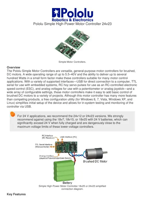
Pololu Simple High-Power Motor Controller 24v23Simple Motor Controllers.OverviewThe Pololu Simple Motor Controllers are versatile, general-purpose motor controllers for brushed, DC motors. A wide operating range of up to 5.5–40V and the ability to deliver up to several hundred Watts in a small form factor make these controllers suitable for many motor control applications. With a variety of supported interfaces—U SB for direct connection to a computer, TTL serial for use with embedded systems, RC hoy servo pulses for use as an RC-controlled electronic speed control (ESC), and analog voltages for use with a potentiometer or analog joystick—a nd a wide array of configurable settings, these motor controllers make it easy to add basic control of brushed DC motors to a variety of projects. Although this motor controller has many more features than competing products, a free configuration utility (for Windows 8, 7, Vista, Windows XP, and Linux) simplifies initial setup of the device and allows for in-system testing and monitoring of the controller via USB.For 24 V applications, we recommend the 24v12 or 24v23 versions. We stronglyrecommend against using the 18v7, 18v15, or 18v25 with 24 V batteries, which cansignificantly exceed 24 V when fully charged and are dangerously close to themaximum voltage limits of these lower-voltage controllers.Simple High-Power Motor Controller 18v25 or 24v23 simplifiedconnection diagram.Key FeaturesSimple bidirectional control of one DC brush motor.5.5 V to 30 V (18v7, 18v15, and 18v25) or 40 V (24v12 and 24v23) operating supply range.7 A to 25 A maximum continuous current output without a heat sink, depending on controller modelFour communication or control options:1. USB interface for direct connection to a PC.2. Logic-level (TTL) serial interface for direct connection to microcontrollers orother embedded controllers.3. Hoy radio control (RC) pulse width interface for direct connection to an RCreceiver or RC servo controller.4. 0–3.3 V analog voltage interface for direct connection to potentiometers andanalog joysticks.Simple configuration and calibration over USB with free configuration program (Windows 8, 7, Vista, Windows XP, and Linux compatible).Note: A USB A to mini-B cable (not included) is required to connect this controller to acomputer.Additional FeaturesComprehensive user’s guide with plenty of connection diagrams and sample code.Adjustable maximum acceleration and deceleration to limit electrical and mechanical stress on the system.Adjustable starting speed, maximum speed, and amount of braking when speed is zero.Optional safety controls to avoid unexpectedly powering the motor.Input calibration (learning) and adjustable scaling degree for analog and RC signals.Under-voltage shutoff with hysteresis for use with batteries vulnerable to over-discharging (e.g. LiPo cells).Adjustable over-temperature threshold and response.Adjustable PWM frequency from 1 kHz to 22 kHz (maximum frequency is ultrasonic, eliminating switching-induced audible motor shaft vibration).Error LED linked to a digital ERR output, and connecting the error outputs of multiple controllers together optionally causes all connected controllers to shut down when any one of them experiences an error.Field-upgradeable firmware.USB/Serial features:Controllable from a computer with native USB, via serial commands sent to the device’s virtual serial (COM) port, or via TTL serial through the device’s RX/TX pins.Example code in C#, Visual Basic .NET, and Visual C++ is available in the Pololu USB Software Development KitOptional CRC error detection to eliminate communication errors caused by noise or software faults.Optional command timeout (shut off motors if communication ceases).Supports automatic baud rate detection from 1200 bps to 500 kbps, or can be configured to run at a fixed baud rate.Supports standard compact and Pololu protocols as well as the Scott Edwards Mini SSC protocol and an ASCII protocol for simple serial control from a terminal program.Optional serial response delay for communicating with half-duplex controllers such as the Basic Stamp.Controllers can be easily chained together and to other Pololu serial motor and servo controllers to control hundreds of motors using a single serial line.Two Pololu Simple Motor Controllersenable mixed RC-control of Dagu WildThumper 4WD all-terrain chassis.RC features:1/4 µs pulse measurement resolution.Works with RC pulse frequencies from 10 to 333 Hz.Configurable parameters for determining what constitutes an acceptable RC signal.Two RC channels allow for single-stick (mixed) motor control, making it easy to use two simple motor controllers in tandem on an RC-controlled differential-drive robot (you might find our RC servo Y splitter cables useful for connecting two SMCs to a single RC receiver).RC channels can be used in any mode as limit or kill switches (e.g. use an RC receiver to trigger a kill switch on your autonomous robot).Battery elimination circuit (BEC) jumper can power the RC receiver with 5 V or3.3 V.Analog features:0.8 mV (12-bit) measurement resolution.Works with 0 to 3.3 V inputs.Optional potentiometer/joystick disconnect detection.Two analog channels allow for single-stick (mixed) motor control, making it easy to use two simple motor controllers in tandem on a joystick-controlled differential-drive robot.Analog channels can be used in any mode as limit or kill switches.This video demonstrates the versatility of the Simple Motor Controller by showing how it can be controlled directly from the analog output of a Sharp analog distance sensor—there is no intermediate control board and no programming involved. For more information on this example, including the SMC settings file and a list of parts used, see our blog post about the demo. Simple Motor Controller Comparison TableThe Simple Motor Controllers are available in several input voltage ranges and output current ranges:1significantly exceed 24 V when fully charged. The 24v12 and 24v23 are the much more appropriate controller for 24 V applications. 2 This is the weight of the board without header pins, terminal blocks, or through-hole power capacitor.Included HardwareSimple High-Power Motor Controller 18v15or 24v12, fully assembled.Simple High-Power Motor Controller 18v15or 24v12, partial kit with includedhardware.Most Simple Motor Controllers are available “fully assembled”, with the power capacitor and connectors pre-installed, or with these components included but not soldered in. For example, a fully assembled 18v15 ships as shown in the left picture above, and an 18v15 with included hardware ships as shown in the right picture above (the included hardware consists of a power capacitor, a 40×1 straight 0.1" male header strip, a 5mm-pitch 4-pin terminal block, and a blue shorting block).The connector-free version allows flexibility in choice of connectors and placement of the power capacitor (e.g. on the other side of the board) to accommodate compact installations or to make room for a heat sink.Note: The power capacitor has a significant effect on performance; the includedcapacitor is the minimum size recommended, and bigger ones can be added if there is space. A bigger capacitor might be required if the power supply is poor or far (more than about a foot) from the controller.The included terminal blocks are only rated for 16 A, so we recommend soldering thick wires directly to the connector-free version of the board and using higher-currentconnectors for applications that will exceed the terminal blocks’ ratings.Simple Motor Controller 18v7bottom view with dimensions.Simple High-Power Motor Controller 18v15 or 24v12bottom view with dimensions.Simple High-Power Motor Controller 18v25 or 24v23bottom view with dimensions.Warning: Take proper safety precautions when using high-power electronics. Make sure you know what you are doing when using high voltages or currents! During normal operation, this product can get hot enough to burn you. Take care when handling this product or other components connected to it.Documentation on producer website.。
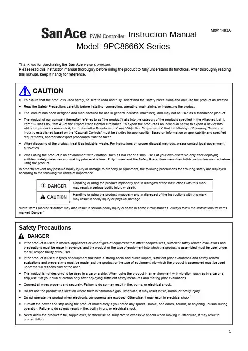
M0011493AThank you for purchasing the San Ace PWM Controller.Please read this instruction manual thoroughly before using the product to fully understand its functions. After thoroughly reading this manual, keep it handy for reference.Safety Precautions●If the product is used in medical appliances or other types of equipment that affect people’s lives, sufficient safety-related evaluations andpreparations must be made in advance, and the product or the type of equipment into which the product is assembled must be used under the full responsibility of the user.●If the product is used in types of equipment that have a strong social and public impact, sufficient prior evaluations and safety-relatedevaluations and preparations must be made, and the product or the type of equipment into which the product is assembled must be used under the full responsibility of the user.●The product is not designed to be used in a car or a ship. When using the product in an environment with vibration, such as in a car or aship, use it at your own discretion only after deploying sufficient safety measures and making prior evaluations.●Connect all wires properly and securely. Failure to do so may result in fire, burns, or electrical shock.●Do not use the product in a location where there is flammable gas. Otherwise, it may result in fire, burns, or bodily injury.●Do not operate the product when electronic components are exposed. Otherwise, it may result in electrical shock.●Turn off the power and stop using the product immediately if you notice any sparks, smoke, odd odors, sounds, or anything unusual duringoperation. Failure to do so may result in fire, bodily injury, or electrical shock.●Never allow the product to fall, topple over, or otherwise be subjected to excessive shocks when moving it. Otherwise, it may result inproduct failure.DANGERInstruction ManualModel: 9PC8666X SeriesHandling or using the product improperly and in disregard of the instructions with this markmay result in bodily injury or physical damage.Handling or using the product improperly and in disregard of the instructions with this markmay result in serious bodily injury or death.CAUTIONDANGER● The product should be handled only by personnel with sufficient training and knowledge and under the full responsibility of the user. ● Never attempt to disassemble, repair, or alter the product in any way, as doing so may result in fire, burns, or electrical shock.Handling● Installation, placement, connections, wiring, or relocation of the product should be performed by knowledgeable or correctly licensed personnel. Never perform such work while the product is on. Failure to do so may result in bodily injury, fire, burns, or electrical shock. ● Never allow yourself to come into contact with the ends of wires or plugs when measuring insulation resistance or dielectric strength voltage. Otherwise, it may result in electrical shock. ● Never attempt to disassemble or alter the product in any way. Doing so may invalidate any warranties concerning the functions or performance of the product, and may also result in fire, burns, bodily injury, or electrical shock.Instruction● Take measures to protect the device from potential damage caused by the product stopping during operation.● Never use the product at voltages, temperatures, or any other settings which exceed those given in the product specifications. Otherwise, it may result in substandard operation, failure, fire, bodily injury, or electrical shock. ● Never remove the product nameplate or install the product so that the identification cannot be seen after installation. Otherwise, it may result in the product being improperly used, and subsequently result in fires. ● Do not turn the power supply ON/OFF on a ground wire. Otherwise, it may result in product failure. ● Do not apply excessive force to the product while it is operating. Otherwise, it may result in product failure.● If you install and use the product in a car or a ship, we shall not be responsible for any faults caused by the environment of the car or ship in which the product is installed.Installation● When fixing the product into place, be sure to take into consideration the product’s weight and all other relevant factors. Failure to do so may result in the product or its parts falling, resulting in bodily injury or device failure. ● Never install or remove the product while it is wired.● When fixing the product with screws, ensure correct tightening torque. If the tightening torque is over the recommended values, the product structure may deform or break. ● Take proper precautions against static electricity when making electrical connections. Failure to do so may result in device or product failure. ● Make electrical connections properly. Failure to do so may result in device failure, product failure, or product malfunction.● Ensure that wires are fitted with insulation to prevent accidental short-circuiting. Failure to do so may result in device failure, product failure, or product malfunction.Operating Environment● Do not use or store the product where it is exposed to flammable or corrosive gas, water or oil splashes, dust or humidity, condensation, radioactive rays or direct sunlight, salty air or saltwater, or where the product may be contaminated by corrosive materials such as sulfurous water, sulfurous volcanic ash, organic solvents, acidic chemicals, alkali chemicals, nuclear fuel materials, or other hazardous substances. If it is used or stored in such places or environments, there is the possibility that a fire may occur, the product may malfunction or its performance may deteriorate. ● Do not use or store the product in locations and environments where it could be constantly exposed to vibrations, strong shocks, magnetic or electromagnetic noise, or in which electromagnetic noise overlaps into power voltage. Otherwise, it may result in product failure. ● Do not use or store the product in environments subject to sudden changes in temperature and humidity. Otherwise, it may result in product failure.Maintenance● Only certified personnel with sufficient training and knowledge should perform maintenance and inspections. Otherwise, it may result in fire, burns, bodily injury, or electrical shock. ● Perform maintenance or inspections while the product is off. Otherwise, it may result in fire, burns, bodily injury, or electrical shock. ● Never use gasoline, paint thinner, benzene, or any other organic solvents to clean the product. Otherwise, it may result in product deformation or substandard operation.CAUTION1. Outline(1) The San Ace PWM Controller is a PWM signal generator that can control the speed of PWM control fans.(2) It can use the same DC power supply (12/24/48) as the connected DC fan(s). The ground wire must share the same power supply. (3) The controller can perform four types of control functions, enabling you to select the best control function to suit your purpose. Onlyone function can be used at a time. (4) The controller can be connected to up to four fans and can be mounted to a DIN rail or mounted with screws.2. Part Names3. MountingThe controller can be mounted to a 35 mm DIN rail or mounted with screws.3-1. Mounting the Controller to a DIN RailSet the controller so that the DIN rail clip is at the bottom. On the rear side, place the controller's upper hook onto the upper lip of the DIN rail and press on the lower part of the controller until you hear a 'click'.3-2. Removing the Controller from a DIN RailWhile pulling down the DIN rail clip using a slotted screwdriver, lift the controller up and away from the rail.3-3. Mounting with ScrewsInsert an M3 screw in each of the four mounting holes and tighten. (Tightening torque: 0.5 N·m max.)Mounting Removing Input terminals (With cover)Mounting holes (4)Power LED (Green)Adjustment knobControl function selector switchPWM output voltage V OH selector switchOutput terminals (With cover)DIN rail clip4. I/O Terminals4-1. Arrangement and FunctionsInput Terminals Terminal FunctionV+Power supply inputV- GroundTH1 Thermistor connection TH2 Thermistor connection C+ Control voltage input C- Control voltage ground or variable resistor connection EA1 Variable resistor connection EA2Variable resistor connectionOutput TerminalsTerminal Function1 to 4PWM signal output4-2. Wiring(1) Remove the terminal cover, insert the wire underneath the screw head, andtighten the terminal screw. (M3 terminal screw, tightening torque: 0.5 N·m max.) (2) Connect the solderless terminal.(3) After confirming the wiring, reattach the terminal cover and turn the power on. (4) The PWM signal output may be subject to noise and impedance due to the wiringconditions. Use wires as thick and short as possible.5. Using the PWM Controller5-1. Selecting V OHPWM output voltage V OH can be set to 3.3 V or 5 V using the switch. Select the V OH matching the specifications of the connected fan(s).5-2. Selecting the Control Functions(1) The controller can perform four types of control functions.(2) Make sure only the function being used is ON and that all other functions are OFF. When all functions are OFF or more than onefunction is ON, the output duty cycle will be set to 100%. (3) Turn off the power when changing control functions.Input Terminal ArrangementV+ V- TH1 TH2 C+ C- EA1 EA2Output Terminal Arrangement1 2 3 4Insulationø3.2Recommended Solderless Terminal5.8 max.V OH Selector SwitchVO: Voltage control TH: Thermistor control IA: Internal adjustment control EA: External adjustment controlControl Function Selector SwitchSelected function: ONOther functions: OFF5-3. Description of Control Functions 5-3-1. Voltage Control Function(1) This function controls the output duty cycle by externally applying voltage from 0 to 5 V. (2) Set the VO control function selector switch to ON to use the voltage control function. (3) Do not apply more than 5.5 V to the voltage input terminals. (4)Do not apply control voltage when the power is off.5-3-2. Thermistor Control Function(1) This function automatically controls the output duty cycle by using the controller's temperature set point (30 to 50°C) and anexternal thermistor to detect the temperature. As the temperature detected by the thermistor nears the temperature set point, the fan automatically increases, decreases, or maintains rotational speed.(2) Set the TH control function selector switch to ON to use the thermistor control function. (3) Connect a thermistor only when using the thermistor control function. (4) Confirm the cooling performance of the fan before connecting it. (5) A thermistor is not included so you will need to supply your own.Thermistor specifications: NTC thermistor with cable, R 25 = 10 k Ω, B 25/85 = 3435KTemperature conditions Output duty cycleFanrotational speed (For reference)Temperature set point < Detected temperature Increases Increases Temperature set point > Detected temperature Decreases Decreases Temperature set point ≈ Detected temperatureMaintains MaintainsConnection Diagram for Voltage Control FunctionPower supplyPower supply (0 to 5 VDC)Fan0102030405060708090100012345出力デューティ[%]コントロール電圧[V](C +とC -間)Control Voltage - Output Duty Cycle Characteristics Control ConditionsThermistorConnection Diagram for Thermistor Control FunctionPower supplyFanDeviceAdjust the temperature set point with the adjustment knob, reading the values (°C) on the outer scale.Control voltage [V] (Between C+ and C-) O u t p u t d u t y c y c l e [%]5-3-3. Internal Adjustment Control(1) This function controls the output duty cycle using the adjustment knob.(2) Set the IA control function selector switch to ON to use the internal adjustment control function.5-3-4. External Adjustment Control(1)This function controls the output duty cycle using a variable resistor.(2) Set the EA control function selector switch to ON to use the external adjustment control function. (3) Connect a variable resistor only when using the external adjustment control function. (4)A variable resistor is not included, so you will need to supply your own.Variable resistor specifications: Total resistance = 10 k Ω, resistance taper = BConnection Diagram for External Adjustment Control Function Power supplyVariable resistorFanConnection Diagram for Internal Adjustment Control Function Adjust the output duty cycle with the adjustment knob, reading the values on the inner scalePower supplyFanResistance - Output Duty Cycle Characteristics0102030405060708090100012345678910出力デューティ[%]抵抗値[k Ω](EA2とC-間)* Value before connecting theterminalsInner Scale Reading - Output Duty Cycle Characteristics 01020304050607080901000102030405060708090100出力デューティ[%]調整目盛り[%]O u t p u t d u t y c y c l e [%]Inner scale reading [%]O u t p u t d u t y c y c l e [%] Resistance [k Ω] (Between EA2 and C-)6. Dimensions7. SpecificationsItemSpecificationsRemarksRated voltage 12/24/48 VDCPower consumption 0.2 W Output terminals not connected Operating voltage range 7 to 60 VDCOutput terminalsNumber of output terminals4Same PWM signal sent from 4 terminals Input/output current 20 mA or lower Total from 4 terminalsPWM signal outputHigh-level voltage (V OH )3.3 V or 5 VOutput terminals not connected Low-level voltage (V OL ) 0.4 V or lower Output terminals not connected PWM frequency25 kHzOutput terminals not connectedInsulation resistance10 M Ω or higher using a 500 VDC insulation resistance testerBetween the power supply input terminal and caseDielectric strength 500 VAC (50/60 Hz) for 1 minute Between power supply input terminal and case Mass Approx. 110 g MountingDIN rail or M3 screwsMaterial Case: Plastics Operating temperature range -20 to 70°C Non-condensing Storage temperature range -30 to 70°C Non-condensing Humidity (operating and storage)20 to 85% RHNon-condensing6657(39 max.)4-ø3.5 (Mounting holes)4-ø635.57786(4)2536Warranty8. Product(1) The warranty period is one year from the date of shipment.(2) If the product fails within the warranty period under normal and proper use based on the contents of this instruction manual, theproduct will be repaired at no cost or be replaced with a new or equivalent product.(3) The warranty does not cover repairs in the following cases:●Failure or defects caused by improper handling such as dropping or applying an excessive force.●Failure or defects caused by disassembling, altering, or repairing the product by the user.●Failure or defects caused by external factors such as fires, natural disasters, pollution, salt damage, corrosive gas, and abnormalvoltages.●Failure or defects found not to be the responsibility of SANYO DENKI. SANYO DENKI CO., LTD. TEL: +81 3 5927 10203-33-1 Minami-Otsuka, Toshima-ku, Tokyo 170-8451, JapanSANYO DENKI EUROPE SA. TEL: +33 1 48 63 26 61P.A. Paris Nord Ⅱ, 48 Allée des Erables-VILLEPINTE, BP.57286, F-95958 ROISSY CDG Cedex, FranceSANYO DENKI AMERICA, INC. TEL: +1 310 783 5400468 Amapola Avenue Torrance, CA 90501, U.S.A.SANYO DENKI SHANGHAI CO., LTD. TEL: +86 21 6235 1107Room 2106-2110, Bldg A, Far East International Plaza, No.319, Xianxia Road, Shanghai, 200051, ChinaBeijing Branch TEL: +86 10 6522 2160 Room1222, Tower B, Beijing COFCO Plaza, No.8 Jianguomennei Dajie, Dong Cheng District, Beijing 100005 ChinaSANYO DENKI (H.K.) CO., LIMITED TEL: +852 2312 6250Room 2305, 23/F, South Tower, Concordia Plaza, 1 Science Museum Rd., TST East, Kowloon, Hong KongTianjin Representative Office TEL: +86 22 2320 1186Room AB 16th Floor TEDA Building, No. 256 Jie Fang Nan Road, Hexi District, Tianjin 300042 ChinaChengdu Representative Office TEL: +86 28 8661 6901Room2105B, Block A, Times Plaza, 2 Zongfu Road, Jinjiang District, Chengdu, 610016 ChinaSANYO DENKI TAIWAN CO., LTD.TEL: +886 2 2511 3938N-711, 7F, Chia Hsin 2nd Bldg., No.96, Sec.2, Zhongshan N. Rd., Taipei 10449, Taiwan (R.O.C.)SANYO DENKI SINGAPORE PTE.LTD.TEL: +65 6223 1071988 Toa Payoh North, #04-05/06/07/08, Singapore 319002Indonesia Representative Office TEL: + 62 21 252 3202Summitmas II 4th Floor, Jl. Jend. Sudirman Kav.61-62, Jakarta 12190, IndonesiaSANYO DENKI GERMANY GmbH TEL: +49 6196 76113 0Frankfurter Strasse 80-82, 65760 Eschborn, GermanySANYO DENKI KOREA CO., LTD. TEL: +82 2 773 56239F, Sunhwa B/D 89, Seosomun-ro, Jung-gu, seoul, 04516, KoreaBusan Branch TEL: +82 51 796 51518F, CJ Korea Express Bldg., 119, Daegyo-ro, Jung-gu, Busan, 48943, KoreaSANYO DENKI (Shenzhen) CO., LTD. TEL: +86 755 3337 38682F 02-11, Shenzhen International Chamber of Commerce Tower, No.168 Fuhua 3 Road, Futian District, Shenzhen, 518048 ChinaSANYO DENKI (THAILAND) CO., LTD. TEL: +66 2261 8670388 Exchange Tower, 25th Floor, Unit 2501-1, Sukhumvit Road, Klongtoey, Klongtoey, Bangkok 10110 ThailandSANYO DENKI INDIA PRIVATE LIMITED TEL: +91 44 420 384 72#14 (Old No.6/3), Avenue Road, Nungambakkam, Chennai - 600034, Tamil Nadu, IndiaThe names of companies and/or their products specified in this manual are the trade names, and/or trademarks and/or registered trademarks of such respective companies.*Specifications are subject to change without notice.Translated version of the original instructions。
User’s ManualHS200Smart Wi-Fi Light SwitchCopyright & TrademarksSpecifications are subject to change without notice. is a registered trademark of TP-LINK TECHNOLOGIES CO., LTD. Other brands and product names are trademarks or registered trademarks of their respective holders.No part of the specifications may be reproduced in any form orby any means or used to make any derivative such as translation, transformation, or adaptation without permission from TP-LINK TECHNOLOGIES CO., LTD.Apple and App Store are trademarks of Apple Inc., registered in the U.S. and other countries.Android and the Google Play logo are trademarks of Google Inc.© 2016 TP-LINK. All rights reserved.Contents4 Introduction6 Product Requirements6 Smart Wi-Fi Light Switch Installation 9 Using Kasa with Smart Switches9 Kasa Account10 Kasa Settings10 Customizing Smart Switches12 Scheduling13 Creating Scenes15 Away Mode17 Runtime Summary18 Maintaining the Smart Switches18 Firmware Update19 Resetting21 Troubleshooting21 Frequently Asked Questions23 Usage Tips23 Support24 Specifications25 Limited WarrantyIntroductionTP-LINK Smart Wi-Fi Light Switch is a standard, single-pole, wall light switch that can be controlled via your iOS or Android devices. Along with the TP-LINK Kasa mobile app, you can follow an intuitive wiring instructions provided to replace your standard in-wall switch, connect the Smart Switch to your home network, then control your lights and create custom lighting automations from anywhere, at anytime with an Internet connection.The Smart Switch is compatible with incandescent, LED, Halogen, and compact fluorescent lightbulbs. The switch also includes a white backlightLED indicator to easily locate the switch at night.Blinking Amber and Green: App-Config mode initiated.Green: Lit up for about 30 seconds when successfully connected to the Wi-Fi network, then turn off.Blinking Amber: Resetting.Red: No Wi-Fi connection.White: Lit up when the light is switched OFF to show the Smart Switch location in the dark.Press to reboot the Smart Switch.Press and hold (about 5 seconds)until the Wi-Fi status LED blinks amber and green alternately to initiate App-Config mode.Press and hold (about 10 seconds)until the Wi-Fi status LED blinks amber rapidly to factory reset theSmart Switch.RESET RES TARTProduct Requirements• In-wall installation with hardwired connections.• Neutral wire required.• Single-pole light switch. The electrical box should be more than 2 inches deep.• A smartphone or tablet running iOS 8 or higher;Android 4.1x or higher.• A Wi-Fi connection (supports 802.11b/g/nstandard).Smart Wi-Fi Light Switch Installation Important Safety InformationBefore installing, servicing, or removing the Smart Switch, read and follow all safety precautions, including the following:• WARNING: RISK OF ELECTRIC SHOCK OR FIRE.Turn OFF power supply at the circuit breaker orfuse. Use a noncontact voltage tester to ensure the power is off.• The Smart Switch must be installed and used in accordance with the National Electric Code (NEC)or your local electrical code. If you are unfamiliarwith these codes and requirements, or areuncomfortable performing the installation, consulta qualified electrician.• The Smart Switch is an indoor single-pole switch that requires a neutral connection.• Do not install the Smart Switch with wet hands or when standing on wet or damp surfaces.1 Download TP-LINK Kasa from App Store or GooglePlay.ORScan QRcode2 Connect mobile device to your 2.4GHz Wi-Finetwork.Note: The Smart Switch only supports 2.4GHznetworks.3 Remove the faceplate from the Smart Switch.Lauch Kasa and follow the wiring steps provided to instal and connect the Smart Switch to your home network.WelcomehomeATTENTION: A neutral wire is required to install theSmart Wi-Fi Light Switch.Using Kasa with Smart SwitchesKasa AccountWhile you don’t have to have a Kasa account to use TP-LINK Smart Home devices, signing up for an account provides added functionality such as:• Synchronization of settings and configurations to all your mobile devices.• Ability to control and configure the devices from outside your home.• Use of third-party services and products such as Amazon Echo.Devices can only be associated with one Kasa account. To remove the association, turn off Remote Control in the Kasa’s settings, or factory reset the device.After creating your Kasa account, you will need to verify the email associated with your account by clicking a link in an email that Kasa sends you. Until you verify the email, much of the above functionality will not work.Kasa SettingsKasa Settings allows you to set your global preferences such as:• Remote Control to control your Smart Home devices outside of your home. You need to sign in to your Kasa account first to turn on this function.• Location and Time to set the location and time of where the Smart Home devices are located sothat the Away Mode and Schedules can run ontime. You can set your home’s location using yoursmart device’s GPS function, or manually enter the latitude and longitude coordinates.• Firmware Update to update your Smart Home devices when there is an update available. Refer to Firmware Update for instructions.Customizing Smart SwitchesYou can personalize your Smart Switches with a descriptive name, icon, and other information from the switch’s details screen.Device Settings1. On the Devices screen, tap on the row of the SmartSwitch to go to its controls.2. Tap the (Settings) icon at the top-right corner.3. On the Device Settings screen, tap the icon foreach setting you want to personalize.• Device Name – Create a unique name for your Smart Switch.• Device Icon – Choose one of the available icons or use your own custom icon.SchedulingYou can set up your lights to illuminate around your home at specific times on specific days of the week.Schedules No events yet!SAVECANCEL Create EventAtTurn my Smart Plug Repeating every701802am 559458600pm :S M T W T F SON1. On the Devices screen, tap on the row of the Smart Switch that you want to create a schedule for.2. Tap(Schedule) to open the Schedule screen.3. Tap to create an event.4. Within the Create Event screen, set your preferred state for the light bulb (ON or OFF), time, and day(s).5. Tap Save .You can create as many events as you like and edit them at any time from the Schedule screen.Creating ScenesTake full advantage of your TP-LINK Smart Home devices in your home with “Scenes”. A scene is a preset group of Smart Devices (such as Smart Plugs and Smart Switches) that can be customized and controlled simultaneously at the touch of a button from your smartphone or tablet to easily set your mood or fit any special occasion. For example, set a customized “Movie Time” to turn on the home theater system pluggedinto a Smart Plug and dim down the lights in your Entertainment Room to 10% at the same time.Please keep in mind that SCENES can only be set and controlled once you’re signed in to your Kasa account.User’s Manual Smart Wi-Fi Light Switch Scenes let you set the mood of yourhome in one tap.Good Morning Movie NightGood NightCustom Scenes1. On the main Home screen, tap the (Scenes) tabto switch to the Scenes view.2. Choose one of the preset scenes to start, orchoose Custom to set up your own scene that ispersonalized to suit your liking. To set a scene,you will need to select one or more devices to becontrolled, and then define their actions and/orstates.User’s ManualSmart Wi-Fi Light SwitchPREVIEWMain Kitchen LightsSide Kitchen LightsParty Bulb NextSet Scene Note that you must have at least one Smart Device in order to create a scene.Away ModeAway Mode allows you to automate your Smart Switches in combination with other Smart Home products to respond to your specific schedules. For example, turn on and off Smart Devices at certain intervals to simulate occupancy when you’re away from home.Away Mode SchedulesDevicesSelect DevicesHow about picking one light from each room?Party BulbSAVE 1. Tap the (navigation drawer) and then AwayMode .2. Tap Select Devices to select your Smart Home devices, and then tap Save .3. If you want to set a schedule to automate Away Mode so you don’t have to manually activate it, tap Set Schedule .Note: Multiple schedules can be set to repeat weekly on the day(s) of your choice.4. Within the Create Event screen, set your preferred mode (Away or Home), time, and day(s).5. Tap Save.You can always toggle Away Mode on and off in the sidebar by tapping on the translucent button under the Kasa logo.Runtime SummaryThe Runtime summary provides a statistical information about how long the Smart Switch has been running. To view the Runtime summary, tap on the Runtime section in the Smart Switch’s details screen.Current Runtime 2.80hrs Total Runtime 3.10hrsDaily Average 5.00hrs Total Runtime 35.0hrsRuntimeDaily Average 4.00hrs Total Runtime 120hrsMaintaining the Smart Switches Firmware UpdateTo keep the Smart Switches happy and up-to-date with all the latest improvement and fixes, we recommend that you update the firmware when updates are available.Firmware UpdateNew Updates Available Smart PlugsSmart Bulb HS100Smart Bulb HS120Updating fi rmwarePlease do not unplug your devices duringthe update.25%This process may take a few minutes.1. Launch Kasa.2. Tap the (navigation drawer) and then Settings.3. Tap Firmware Update.4. Within the Firmware Update screen, tap Update.Remember: Only the Smart Switches that are currently reachable and have an available update will be shown in the Firmware Update screen.It is important to leave the Kasa app running whileit finishes updating the Smart Switches. Try not to minimize the app, close the app, or interrupt the update to prevent problems.ResettingResetting the Smart Switch can help you troubleshoot any issues you may have. Please keep in mind that factory resetting a device will erase all of your custom settings and restore them to factory default settings.RESE TThe RESET button located underneath the Smart Switch has two functions:• Press and hold (about 5 seconds) until the Wi-Fi status LED blinks amber and green alternately to initiate App-Config mode.• Press and hold (about 10 seconds) until the Wi-Fi status LED blinks amber rapidly to reset the Smart Switch to factory defaults. Note that factory setting the Smart Switch will erase all of your custom settings, and you’ll have to set it up again.TroubleshootingFrequently Asked Questions1. What should I do when I can’t turn the Smart Switchon/off manually?If the Smart Switch doesn’t respond when pressing the physical switch:• Make sure that you restore power to the Smart Switch at the circuit breaker.• Make sure the Smart Switch is wired correctly.Please consult with a qualified electrician.2. What should I do when the Smart Switch won’trespond to commands or scheduled automations?• Check your network connectivity.• Check if the Wi-Fi status LED on the Smart Switch is blinking amber and green. If so,reconnect the Smart Switch to your Wi-Finetwork.• Do not use a metal faceplate with the Smart Switch to prevent Wi-Fi signal interference.• Power cycle your router and/or reboot theSmart Switch by pressing the RESTART buttonunderneath the switch.• Factory reset the Smart Switch by pressing and holding the RESET button. You’ll need toreconfigure the Smart Switch again.3. How far can I be and still able to control my lightsvia the Smart Switch?You can be anywhere in the world and still able tocontrol your lights as long as you have an activeInternet connection and Remote Control enabled.4. Can I install two or more Smart Switches to controlone light fixture?No. The Smart Switch is designed for single-pole(one location) wiring only and requires a neutralwire for operation.5. How do I pair the Smart Switches with AmazonEcho?For pairing instructions, please visit www.tp-link.com/en/faq-944.html or within the Kasa Helpsection.Usage Tips• Place the Smart Switch within the range of your Wi-Fi router or access point (approximately 150 feet).• Avoid physical obstructions and radio interference in the surrounding area.SupportShould you encounter any issues with the Smart Wi-Fi Light Switch, please visit our support page at /support for web support and troubleshooting information.SpecificationsHeight 4.13 in (10.5 cm)Width 1.75 in (4.45 cm)Depth 1.75 in (4.45 cm)Color White3-Way No4-Way NoLocator Light YesNumber of Poles1Wall Plate IncludedPower100-120 V ~ 50/60 Hz.Maximum Loads600W incandescent.Operating Temp.32o-104o F (0o-40o C)For indoor use onlyLimited WarrantyTo learn more about the Limited Warranty for TP-LINK products, please visit /support/rma.FCC StatementThis equipment has been tested and found to comply with the limits for a Class B digital device, pursuant to part 15 of the FCC Rules. These limits are designed to provide reasonable protection against harmful interference ina residential installation. This equipment generates, uses and can radiate radio frequency energy and, if not installed and used in accordance withthe instructions, may cause harmful interference to radio communications. However, there is no guarantee that interference will not occur in a particular installation. If this equipment does cause harmful interference to radio or television reception, which can be determined by turning the equipment off and on, the user is encouraged to try to correct the interference by one or more of the following measures:• Reorient or relocate the receiving antenna.• Increase the separation between the equipment and receiver.• Connect the equipment into an outlet on a circuit different from that to which the receiver is connected.• Consult the dealer or an experienced radio / TV technician for help.This device complies with part 15 of the FCC Rules. Operation is subject to the following two conditions:1) This device may not cause harmful interference.2) This device must accept any interference received, includinginterference that may cause undesired operation.Any changes or modifications not expressly approved by the party responsiblefor compliance could void the user’s authority to operate the equipment. Note: The manufacturer is not responsible for any radio or TV interferencecaused by unauthorized modifications to this equipment. Such modifications could void the user’s authority to operate the equipment.FCC RF Radiation Exposure StatementThis equipment complies with FCC RF radiation exposure limits set forth for an uncontrolled environment. This device and its antenna must not be co-located or operating in conjunction with any other antenna or transmitter.“To comply with FCC RF exposure compliance requirements, this grantis applicable to only Mobile Configurations. The antennas used for this transmitter must be installed to provide a separation distance of at least 20 cm from all persons and must not be co-located or operating in conjunction with any other antenna or transmitter.”CE Mark WarningThis is a class B product. In a domestic environment, this product may cause radio interference, in which case the user may be required to take adequate measures.RF Exposure InformationThis device meets the EU requirements (1999/5/EC Article 3.1a) on the limitation of exposure of the general public to electromagnetic fields by way of health protection.The device complies with RF specifications when the device used at 20 cm from your body.Canadian Compliance StatementThis device complies with Industry Canada license-exempt RSSs. Operation is subject to the following two conditions:1) This device may not cause interference, and2) This device must accept any interference, including interference that maycause undesired operation of the device.Le présent appareil est conforme aux CNR d’Industrie Canada applicables aux appareils radio exempts de licence. L’exploitation est autorisée aux deux conditions suivantes :1) l’appareil ne doit pas produire de brouillage;2) l’utilisateur de l’appareil doit accepter tout brouillage radioélectriquesubi, meme si le brouillage est susceptible d’en compromettre lefonctionnement.Radiation Exposure StatementThis equipment complies with IC radiation exposure limits set forth for an uncontrolled environment. This equipment should be installed and operated with minimum distance 20cm between the radiator and your body.Déclaration d’exposition aux radiationsCet équipement est conforme aux limites d’exposition aux rayonnementsIC établies pour un environnement non contrôlé. Cet équipement doit être installé et utilisé avec un minimum de 20 cm de distance entre la source de rayonnement et votre corps.Industry Canada StatementCAN ICES-3 (B)/NMB-3(B)Korea Warning Statements당해 무선설비는 운용중 전파혼신 가능성이 있음.NCC Notice注意! 依據 低功率電波輻射性電機管理辦法第十二條 經型式認證合格之低功率射頻電機,非經許可,公司、商號或使用者均不得擅自變更頻率、加大功率或變更原設計之特性或功能。
目录1. LCD显示功能概述 (1)2. 按键功能 (2)2.1. 按键功能码速查表 (2)2.2. 按键模式说明 (2)2.3. 数据设置方法 (2)3. 按键操作说明 (3)3.1. 主变量调零(清零)功能 (3)3.2. 组态功能 (3)3.2.1. 功能概述 (3)3.2.2. 设置单位 (4)3.2.3. 设置量程和阻尼 (4)3.3. 组态数据浏览 (4)H3051S / H3051T 按键使用说明书1. LCD 显示功能概述用户可以通过组态软件设置LCD 显示的变量及显示的小数位数。
参见组态软件设置部分的“仪表组态”→“输出特性”。
LCD 支持双变量显示,可以设置的显示变量包括电流、主变量百分比和主变量;每个变量的均可以独立设置显示小数点位置:0、1、2、3、4。
如果两个显示变量相同,则LCD 只显示一种变量;否则,LCD 将以3秒的时间间隔,交替显示所设置的显示变量。
其它显示说明: ¾若在通讯状态,闪烁显示LCD 左上角的。
¾若为开方输出,LCD 显示。
¾若固定输出电流,LCD 显示。
¾若启动写保护,LCD 显示。
¾若启动温度显示,在实时正常显示是,LCD 左下角“88”字符显示温度,温度小于-19℃或大于99℃显示。
2.按键功能通过按键可以调零;零点迁移、量程迁移;设置单位、量程、阻尼。
也可以通过按键查看单位、量程、阻尼等组态数据。
2.1. 按键功能码速查表现场使用按键组态时,LCD左下角“88”字符用于表示当前设置变量类型,也就是当前按键所执行的设置功能。
其对应关系为:左下角“88”字符显示设置变量0或空正常显示1 输入操作码(可以直接输入和下面功能对应的数字,以直接进行相应功能的设置)2 设置单位3 设置量程下限4 设置量程上限5 设置阻尼6 主变量调零7 零点迁移与量程迁移注:通过输入各个功能对应的操作码,可以快速进入对应功能。
Digital Power Controllers数字功率控制器JS2000 SeriesJS2000系列Two phase control ofThree-phase load两控三相负载User Manual用户手册©Copyright JETTER Automation 2005JS2000JS2000USER MANUAL用户手册CONTENTS目录PRECAUTIONS . . . . . . . . . . . . . . . . . . . . . . . . . . . . . . . . . . . . . . . . . . . . . . . . . . . . . . .4 Chapter 1 IDENTIFYING THE CONTROLLERS . . . . . . . . . . . . . . . . . . . . .5第一章控制器信息GENERAL INTRODUCTION TO THE JS2000 SERIES . . . . . . . . . . . . .5JS2000系列概述TECHNICAL SPECIFICATION . . . . . . . . . . . . . . . . . . . . . . . . . . . . . . . .8技术说明PRODUCT CODE . . . . . . . . . . . . . . . . . . . . . . . . . . . . . . . . . . . . . . . . . .11选型代码EXAMPLE OF PRODUCT CODE . . . . . . . . . . . . . . . . . . . . . . . . . . . . . .12选型样例Chapter 2 INSTALLATION . . . . . . . . . . . . . . . . . . . . . . . . . . . . . . . . . . . . . .13第二章安装INSTALLATION - SAFETY . . . . . . . . . . . . . . . . . . . . . . . . . . . . . . . . . . .13安装安全规范DIMENSIONAL DETAILS . . . . . . . . . . . . . . . . . . . . . . . . . . . . . . . . . . . .14详细产品尺寸说明MOUNTING DETAILS . . . . . . . . . . . . . . . . . . . . . . . . . . . . . . . . . . .. . . .15详细安装尺寸说明Chapter 3 WIRING . . . . . . . . . . . . . . . . . . . . . . . . . . . . . . . . . . . . . . . . . . . .16第三章接线WIRING - SAFETY . . . . . . . . . . . . . . . . . . . . . . . . . . . . . . . . . . . . . . . . .16接线规范POWER WIRING . . . . . . . . . . . . . . . . . . . . . . . . . . . . . . . . . . . . . . . . .. .17主回路动力线USER TERMINAL BLOCKS . . . . . . . . . . . . . . . . . . . . . . . . . . . . . . . . . .18用户接线端子图Chapter 4 CONFIGURATION . . . . . . . . . . . . . . . . . . . . . . . . . . . . . . . . . . . .21第四章配置CONFIGURATION - SAFETY . . . . . . . . . . . . . . . . . . . . . . . . . . . . . . . . .21配置安全规范DRIVER BOARD CONFIGURATION . . . . . . . . . . . . . . . . . . . . . . . . . .. .22触发板配置说明Chapter5 OPERATION . . . . . . . . . . . . . . . . . . . . . . . . . . . . . . . . . . . . . . . . .24第五章操作CONTROL OPERATION . . . . . . . . . . . . . . . . . . . . . . . . . . . . . . . . . .. . . .24控制操作THYRISTOR FIRING MODES . . . . . . . . . . . . . . . . . . . . . . . . . . . . . . .. . .25晶闸管触发模式Chapter 6 COMMISSIONING PROCEDURE . . . . . . . . . . . . . . . . . . . . . . . .28试运行操作步骤COMMISSIONING PROCEDURE - SAFETY . . . . . . . . . . . . . . . . . . . .. . .28试运行安全规范CHECKING THE CHARACTERISTICS . . . . . . . . . . . . . . . . . . . . . . . . . . .29检查特征POWERING UP THE CONTROLLER . . . . . . . . . . . . . . . . . . . . . . . . . . . ..30控制器上电Chapter 7 DISPLAY MESSAGES. . . . . . . . . . . . . . . . . . . . . . . . . . . .. . . . . 31第七章显示信息GENERAL . . . . . . . . . . . . . . . . . . . . . . . . . . . . . . . . . . . . . . . . . . . . . . . . .. 31概述STEADY MESSAGES . . . . . . . . . . . . . . . . . . . . . . . . . . . . . . . . . . . . . . . 31直亮信息FLASHING MESSAGES . . . . . . . . . . . . . . . . . . . . . . . . . . . . . . . . . . . . . . 32数码管信息ERROR . . . . . . . . . . . . . . . . . . . . . . . . . . . . . . . . . . . . . . . . . . . . . . . . . . 32错误FAILURES . . . . . . . . . . . . . . . . . . . . . . . . . . . . . . . . . . . . . . . . .. . . . . . . . . 32故障MICROPROCESSOR FAILURE . . . . . . . . . . . . . . . . . . . . . . . .. . . . . . . . . 32微处理器故障Chapter 8 ALARMS. . . . . . . . . . . . . . . . . . . . . . . . . . . . . . . . . . . . . . . . . . . . 35第八章报警ALARM STRATEGY . . . . . . . . . . . . . . . . . . . . . . . . . . . . . . . . . . . . . . . . . . 35报警策略ALARM RELAYS . . . . . . . . . . . . . . . . . . . . . . . . . . . . . . . . . . . . . . . . . . . .. 36报警继电器ALARM ACKNOWLEDGEMENT . . . . . . . . . . . . . . . . . . . . . . . . . . . . . . . .. 36报警常识Chapter 9 MAINTENANCE . . . . . . . . . . . . . . . . . . . . . . . . . . . . . . . . . . . . . . . .37第九章维护FUSES . . . . . . . . . . . . . . . . . . . . . . . . . . . . . . . . . . . . . . . . . . . . . . . . . . . . . 37快熔保险SERVICING . . . . . . . . . . . . . . . . . . . . . . . . . . . . . . . . . . . . . . . . . . . . . . . . .38维修PRECAUTIONS警告Safety symbols安全标志Important safety precautions and special information are indicated in the text of the manual bytwo symbols:重要安全警告和特殊信息在本手册中用以下两个标志阐明:DANGER危险This symbol means that failure to take note of the information given in thismanual may have serious consequences for the safety of personnel and mayeven result in electrocution.这个标志说明如果操作失误可能会引起严重的人员安全问题,可能会造成人员触电的后果。

伺服驱动器上位机软件HMServo说明书(V 2.0)目录1 软件概述 (3)1.1 软件介绍 (3)1.2 软件功能 (3)1.2.1 系统名称 (3)1.2.2 核心功能 (3)2 软件使用 (4)2.1 参数配置功能 (4)2.1.1 基本配置 (4)2.1.2 电机编码器反馈配置 (5)2.1.3 电机参数设置 (8)2.1.4 参数计算 (10)2.1.5 温度保护/Brake功能设置 (10)2.1.6 Endat编码器电机Initphase (11)2.2 三环设置功能 (12)2.2.1 电流环设置 (12)2.2.2 速度环设置 (13)2.2.3 位置环设置 (14)2.3 自动换相功能 (15)2.4 波形监测功能 (18)2.5 波形分析功能 (20)2.6 数字IO功能 (21)2.6.1 数字输入信号配置 (21)2.6.2 数字输出信号配置 (21)2.7 固件更新功能 (22)2.8 参数管理功能 (23)2.9 用户自定义轨迹功能 (24)2.9.1 UDM主界面 (24)2.9.2 UDM Function简介 (26)2.9.3 常用UDM函数详解 (27)2.10 高级操作面板 (37)2.11 急停功能 (38)3 操作实例 (39)4 常见问题(FAQ) (40)1 软件概述1.1 软件介绍HMServo V2.0是大族电机伺服驱动器系列产品的上位机软件,支持大族电机所有型号的伺服驱动器的联机调试功能,目前所支持的型号有:●ST3-S-4/230Vac●ST3-S-15/380Vac●ST3-S-30/380Vac●ST3-S-50/380Vac●ST3-S-15/150Vdc●ST3-S-6/220Vac共6款驱动器,功率涵盖从500W到30kW ,其中ST3-S-15/150Vdc是直流供电高性能驱动器,其他型号为交流供电高性能驱动器;驱动器型号各字段的含义见具体型号硬件说明书。
功率控制器五、轻载实验连接功率控制器输入电源线,断开功率控制器与负载的连线,用两只100W/220V的灯泡(白炽灯功率不得小于100W)做假负载,两只灯泡呈串联连接,分别接到功率控制器的输出端。
打开功率控制面板,将控制电路板上的拨动开关K1由恒流挡拨至开环挡。
接通电源,做以下检查。
1.查看面板指示灯POWER是否亮,风机工作是否正常。
若电源指示灯不亮,风机不转,请按以下步骤检查:A.检查功率控制器的输入电压U1、V1的电压是否正常;B.检查功率控制器的快速熔断器是否熔断。
C.检查控制电路板上JD2接线端子的电压是否与功率控制器的输入电压U1、V1的电压是否一致。
D.检查控制板上电源变压器是否损害。
电源变压器原边或副边线圈是否开路或短路,停电后可检查原边线圈的电阻值正常时应在 1.2—1.5千欧,副边线圈两组的电阻值正常时在9—12欧姆,如损坏请与生产厂房联系。
E.风机工作不正常请检查风机电源连线是否正确。
用万用表测量接线端子A、N两端之间电压是否为交流220V。
若接到380V会导致风机损坏。
2.调节手动调节电位器,输出电压U2、V2两相间的电压应在0—372V范围内(非定值,随输入电网电压而变化)范围内连续可调,并能稳定在任意值。
若功率控制器输出电压不随控制信号的变化而变化,请做一下检查:1)调节手动调味器,功率控制器无电压输出。
a.检查功率控制器输入端U1,V1电压应为380V±10%b.检查手动转换开关应在手动档,K1和K2之间应连通c.检查手动调节电位器(2.2K)接线是否正确;端子WB(K1)和端子GND间的直流电压应在0—6V连续可调。
注意:接线端子WB、K2、K1在此时影视连通的。
d.负载白炽灯的连线开路或白炽灯内部开路,停电后检查功率控制器输出端电阻(所带负载)e.控制电路板损坏,有手动调节的控制信号,无触发可控硅的触发信号。
检测办法:当电位器调节到最大时(K1与GND之间应在6VDC左右),用万用表直流电压档测量G1与T1,G2与T2之间电压应在1—2VDC之间,如果没有电压信号,则可能是控制电路板故障,如损坏请与生产厂方联系。
目录应用范围 (2)功能和特点 (2)控制精度 (5)环境温度........................................................................................................................... 错误!未定义书签。
参数设定单元 (6)变流器的主回路构造及功能 (11)优化过程 (13)可编程报警 (13)端子功能的说明 (14)标准规格 (9)标准连接图 (16)尺寸和重量 (18)应用范围TPD32系列整流装置为三相交流电源直接供电的全数字控制装置,其用途为调节它励直流电动机的速度和转矩。
它的结构紧凑,功能强大,产品性能稳定,可以满足各种生产和工艺的调速要求。
设计电流范围为15至4800A ,并可通过并联可控硅单元进行扩展。
TPD32变流器有两种类型: ∙ TPD32…2B 二象限变流器 ∙ TPD32…4B 四象限变流器功能和特点功能说明TPD32系列直流传动装置的特色是功能强大,即为了满足各种应用的要求,可以灵活的设定和修改参数。
这种直流传动装置可以用不同方法控制: ∙ 端子板 ∙ 键盘∙ RS485串行接口 ∙ 总线连接(可选)所需设定值是通过更改CONFIGURATION menu(配置菜单)中的Main commands(主指令)和Control mode(控制方式)参数来实现。
该装置装有在MS-WINDOWS TM环境下使用的用户接口软件,以便通过RS485串行接口来控制传动装置。
装置出厂设定为用级联电流调节的方法进行调速的,并按“标准接线图”所示的接线图连接。
该器件初始试运行只需要将直流电动机的参数输入该软件START UP(起动)菜单中。
然后,可在所有参数通过键盘(START UP/Main Commands(起动/主指令))设定后通过端子板控制传动装置。
如果所需功能在标准配置中不存在,则可以通过相应的菜单选择这些功能并设定它们的参数。
功率控制器五、轻载实验连接功率控制器输入电源线,断开功率控制器与负载的连线,用两只100W/220V的灯泡(白炽灯功率不得小于100W)做假负载,两只灯泡呈串联连接,分别接到功率控制器的输出端。
打开功率控制面板,将控制电路板上的拨动开关K1由恒流挡拨至开环挡。
接通电源,做以下检查。
1.查看面板指示灯POWER是否亮,风机工作是否正常。
若电源指示灯不亮,风机不转,请按以下步骤检查:A.检查功率控制器的输入电压U1、V1的电压是否正常;B.检查功率控制器的快速熔断器是否熔断。
C.检查控制电路板上JD2接线端子的电压是否与功率控制器的输入电压U1、V1的电压是否一致。
D.检查控制板上电源变压器是否损害。
电源变压器原边或副边线圈是否开路或短路,停电后可检查原边线圈的电阻值正常时应在 1.2—1.5千欧,副边线圈两组的电阻值正常时在9—12欧姆,如损坏请与生产厂房联系。
E.风机工作不正常请检查风机电源连线是否正确。
用万用表测量接线端子A、N两端之间电压是否为交流220V。
若接到380V会导致风机损坏。
2.调节手动调节电位器,输出电压U2、V2两相间的电压应在0—372V范围内(非定值,随输入电网电压而变化)范围内连续可调,并能稳定在任意值。
若功率控制器输出电压不随控制信号的变化而变化,请做一下检查:1)调节手动调味器,功率控制器无电压输出。
a.检查功率控制器输入端U1,V1电压应为380V±10%b.检查手动转换开关应在手动档,K1和K2之间应连通c.检查手动调节电位器(2.2K)接线是否正确;端子WB(K1)和端子GND间的直流电压应在0—6V连续可调。
注意:接线端子WB、K2、K1在此时影视连通的。
d.负载白炽灯的连线开路或白炽灯内部开路,停电后检查功率控制器输出端电阻(所带负载)e.控制电路板损坏,有手动调节的控制信号,无触发可控硅的触发信号。
检测办法:当电位器调节到最大时(K1与GND之间应在6VDC左右),用万用表直流电压档测量G1与T1,G2与T2之间电压应在1—2VDC之间,如果没有电压信号,则可能是控制电路板故障,如损坏请与生产厂方联系。
目录1.产品概述 (1)1.1.简介 (1)1.2.应用领域简介 (1)1.3识别网络摄像机部件 (2)1.3.1产品外观图 (2)1.3.2网络摄像机接口说明 (2)2.功能介绍 (3)2.1.基本功能介绍 (3)2.2.高级功能介绍 (3)2.3.系统需求 (4)3.安装向导 (5)3.1.网络摄像机的网线及电源连接; (5)3.2.网线连接到路由器(R OUTER)/交换机(S WITCH)/集线器(H UB) (6)4.访问摄像机 (7)4.1.网页浏览器访问摄像机 (7)4.2.使用查找器 (7)4.3.系统登录 (8)4.4.功能操作 (10)4.5.摄像机设置 (11)4.5.1设备信息 (11)4.5.2.名称设置 (12)4.5.3.时钟设置 (12)4.5.4.用户设置 (13)4.5.5.RTSP设置 (13)4.5.6.多画面设置 (13)4.5.7.基本网络设置 (14)4.5.8.无线局域网设置 (15)4.5.9.PPPoE设置 (15)4.5.10.UPnP设置 (16)4.5.11.动态域名设置 (16)4.5.12.视频配置 (16)4.5.13.邮件服务器 (17)4.5.14.FTP服务器 (17)4.5.15.报警服务设置 (18)4.5.16.SD卡录像 (18)4.5.17.SD卡录像回放 (19)4.5.18.本地录像 (19)4.5.19.云台设置 (20)4.5.20.日志 (20)5.手机访问 (21)5.1.智能手机访问 (21)6.其他 (26)6.1路由器端口映射设置 (26)7.常见问题解答 (27)8.产品保修 (28)8.1.保修说明 (28)8.2.产品保修卡 (29)1.产品概述1.1.简介本系列产品是针对网络视频监控而开发的一体化网络摄像机,包括有线网络枪机、无线网络枪机、网络红外半球机、网络红外防水机等。
采用高性能芯片实现对音视频采集、压缩、传输于一体的媒体处理器,标准的H.264编码算法确保了更清晰、更流畅的视频传输效果。
杭州美控自动化技术有限公司更多资讯请扫二维码服务电话:400-152-1718杭州美控自动化技术有限公司 U-PH3-MKCN1第1版pH/ORP控制器使用说明书前言 前言感谢您购买本公司的pH/ORP控制器。
本手册简明地介绍了pH/ORP 控制器的安装、接线及操作说明。
为了确保正确使用本产品,请在使用之前先阅读本手册。
注意●因本产品的性能和功能会不断改进,本手册内容如有更改,恕不另行通知。
●本公司力求本手册的正确、全面。
如有错误、遗漏,请和本公司联系。
版本U-PH3-MKCN1 第一版2018年8月安全注意事项安全注意事项为了安全使用本产品,操作时请务必遵守此处描述的安全注意事项。
关于本手册●请将本手册交于操作者阅读。
●在操作之前,请熟读本手册,并对产品有深入了解。
●本手册只对产品的功能进行阐述,本公司不保证该产品将适合于用户的某一特殊用途。
本产品保护,安全及改造相关注意事项●为了确保安全使用本产品以及由其控制的系统,操作时请务必遵守本手册中所述说明和注意事项。
如果违反操作规程,则有可能会损坏本产品所提供的保护功能。
对由以上情况产生的质量、性能、功能和产品的安全问题,本公司不承担任何责任。
●为本产品及其控制系统安装防雷装置,或为本产品及其控制系统设计安装单独的安全保护电路时,需要借助其他的设备来实现。
●如需更换产品的零部件,请使用本公司指定的型号规格。
●本产品不适用于直接关系到人身安全的系统。
如核动力设备、使用放射能的设备、铁路系统、航空机器、船舶设备、航空设备和医疗器械等。
如有应用,用户有责任使用额外的设备或系统确保人身安全。
●请勿改造本产品。
安全注意事项 在本手册中使用以下几种安全标志:危险标志,若不采取适当的预防措施,将导致严重的人身伤害、产品损坏或重大财产损失等事故。
警示标志,提醒您对产品有关的重要信息或本手册的特别部分格外注意。
●在接通本产品的电源之前,请先确认产品的电源电压是否与供给电源电压一致。
9.1机柜9.1.1 IH设备9.1.1-1 IH设备- 功能说明这种两路高频发生器用于:•TS - 横向的密封(A502)•LS - 纵封(A501)SA - 带涂药(7417)脉冲持续时间由PLC程序来控制。
功率电平设置TPOP显示位于控制。
三相400V和24V DC,供给发生器。
每个TPIH-2500系统主要由:•电位计(1)•TPIH2500发生器(2)同轴电缆(3)(4)阻抗变换器1电位2 TPIH2500发生器3同轴电缆4阻抗变压器TPIH2500发生器主要由:•输出1 X4(5)•输出2 X5(6)•串行连接5233(7)•24V连接X3(8)•400V连接X1(9)•多功能按钮(10)•LED状态指示灯(11)•液晶显示器(12)5输出16输出27串行连接8 24V连接9 400V连接10多功能按钮11 LED液晶显示器(LCD)12LED的描述有触电的危险!当400VAC绿色指示灯熄灭仍然可以有一个或两个连接器X1阶段上。
彩色标签含义绿色24 VDC,当有24v时24 V时。
它关闭时,没有24。
绿色400 VAC当所有3相存在。
为OFF时,至少错过了一个3相。
红色错误是ON时,一个或多个错误发生。
在这种情况下,上液晶显示,操作员可以读取错误发生。
为OFF时,有没有错误条件。
绿色输出1而发电机是通过发送功率输出1为ON为OFF时,输出1为无效。
绿色输出2这是ON而发电机是通过发送功率输出2OFF输出时是无效的。
危险!9.1.1-2 IH设备-LCD显示器用户菜单TPIH2500为用户提供了一个简单的方法访问许多通过在显示屏上显示的菜单中的信息和设置。
一个普通的页面通常是由三部分组成:排在顶部显示网页标题,•以下六个行可以显示命令或信息,•在底部显示的行执行的操作按钮。
每个按钮上的符号或文字说明行动将如果相同的按钮被按下。
在左边的页面有可能的命令的列表。
当前选定的显示命令反向模式(黑底白字)。
EPOW-SS2H太阳能光伏充放电控制模块使用说明书 V2.3MOBOLO EPOW-SS2H系列是基于微处理器控制的智能太阳能充放电管理模块,支持用户可编程,广泛应用于庭院照明、供氧、浇水以及小型户外无人值守系统的电源管理。
产品型号: EPOW-SS5H(5A)/ EPOW-SS2H(2A)/ EPOW-SS1HS(1A)操作界面:M O B OL O小型控制器操作界面应用领域:小型户外无人值守系统,太阳能庭院灯,庭院水系供电增氧,庭院草坪浇水,太阳能路灯,便携式太阳能发电站,太阳能交通警示灯,太阳能航标灯,太阳能换气系统,太阳能杀虫灯(可选雨水传感器),太阳能灯箱、太阳能广告牌…一、功能特点:如用户有特殊规格需求,请联系生产商,提供免费的快速打样服务,供用户评估产品性能。
工作电压6v/12v(SS2H/SS1Hs),12v/24v(SS5H)自动识别,接受其它特种电池或非标电压的产品订单;雨水保护或系统温度保护接口;五档模式控制:纯光控、光控+延时关,光控+延时半亮度、通用(光伏发电,无人值守系统)、时光穿梭;光控启动点可调,内设光滤波算法,自动滤除杂散光干扰;用户可灵活设置四档半功率输出值;最大太阳能板功率:120W (仅EPOW-SS5H-24v)PWM脉冲充电控制,支持蓄电池过冲、过放电保护;太阳能电池板反充保护;太阳能电池板反接保护;支持负载软启动及短路保护;白天/黑夜模式智能识别,不受汽车灯光及其它不稳定光源的干扰;蓄电池状态(充电,过冲,过放,充满)和负载状态(工作,半功率,待机,过载)指示;采用SMT贴片生产工艺,沉金PCB,工艺先进,质量保证;EPOW-SS2H实拍图 1二、技术参数(锂电池或其它非标电压的应用请联系美宝龙科技)三、系统连接;将负载,蓄电池,太阳能电池按上述顺序连接好,正负极如图2所示;注意:不能用其它电源取代太阳能电池接入系统测试,否则可能烧毁控制器!图 2JP1:时钟加速器/雨控传感器接口/温控传感器接口;雨控传感器(选件):提供雨水保护功能;温控传感器(选件):提供系统过热保护功能;JP2为系统功能设置跳线;TC:延时工作时间设置;LCP:光控启动点设置;OPS:光控+延时关闭或半功率设置;四、工作状态指示 -(基于EPOW-SS用户界面)1.负载状态指示(绿色LED):点亮:负载启动,全功率输出;慢闪:负载启动,半功率输出;熄灭:负载停止工作(可能是白天,或延时工作时间结束)休眠状态,蓄电池处于低压保护、或其它系统保护启动,负载被强行切断输出;其原因有过放保护、雨控、温度保护或未达到设定的输出条件;快闪:负载过载或短路触发保护性停机,10秒后重新启动负载;2.充电指示(红色LED)指示蓄电池及充电状态:熄灭:过放电保护,蓄电池欠压,负载输出被强制切断;慢闪:待机状态,蓄电池电压正常,允许启动负载;点亮:正在充电,未充足;快闪:充电终止,电池已经充满;五、系统功能设置 -(基于EPOW-SS用户界面)通过JP2短接帽的不同组合,可以方便的控制EPOW-SS2H的工作方式,操作方法如下文所示。