WiRE 4操作说明 中文
- 格式:pdf
- 大小:3.39 MB
- 文档页数:65


Customer Specification PART NO. M4220ConstructionApplicable Specifications Environmental Alpha Wire | 711 Lidgerwood Avenue, Elizabeth, NJ 07207 Tel: 1-800-52 ALPHA (25742), Web: Diameters (In)1) Component 1 2 X 1 COAXa) Conductor 20 (7/28) AWG TC 0.038b) Insulation 0.0205" Wall, Nom. Polyethylene(PE) 0.079(1) Color(s)Cond Color Cond Color Cond Color1 NATURAL2 NATURAL2) Cable Assembly 2 Components Cableda) Twists: 4.8 Twists/foot (min)3) Shield TC BRAID Shield,85% Coverage, Min.4) Jacket 0.028" Wall, Nom.,Type IIA PVC0.235 (0.245 Max.)a) Color(s) BLACKb) Print ALPHA WIRE-* P/N M4220 RG108 TYPE CE ROHS* = Factory Code1) Military MIL-C-17/ RG 108 TYPE 85°C / 750 V RMS2) CE:EU Low Voltage Directive 2006/95/EC1) CE: EU Directive 2011/65/EU(RoHS2):This product complies with European Directive 2011/65/EU (RoHS Directive)Properties Other of the European Parliament and of the Council of 8 June 2011. No Exemptions are required for RoHS Compliance on this item. Consult Alpha Wire's web site for RoHS C of C.2) REACH Regulation (EC 1907/2006):This product does not contain Substances of Very High Concern (SVHC)listed on the European Union's REACH candidate list in excess of 0.1%mass of the item. For up-to-date information, please see Alpha's REACHSVHC Declaration.3) California Proposition 65:The outer surface materials used in the manufacture of this part meet the requirements of California Proposition 65.Physical & Mechanical Properties1) Temperature Range-40 to 85°C2) Bend Radius 10X Cable Diameter3) Pull Tension 21.4 Lbs, MaximumElectrical Properties(For Engineering purposes only)1) Voltage Rating 750 V RMS2) Characteristic Impedance 78 Ω +/- 73) Inductance 0.119 µH/ft, Nominal4) Mutual Capacitance 19.7 pf/ft @1 kHz, Nominal5) Ground Capacitance 45.1 pf/ft @1 kHz, Nominal6) Velocity of Propagation 66 %7) Conductor DCR 9.5 Ω/1000ft @20°C, Nominal8) OA Shield DCR 5.3 Ω/1000ft @20°C, Nominal9) Attenuation, Nom dB/100ft 0.7 @ 1 MHz2.3 @ 10 MHz5.2 @ 50 MHz7.5 @ 100 MHz11 @ 200 MHz16 @ 400 MHzPackaging Flange x Traverse x Barrel (inches) a) 1000 FT12 x 10 x 5 Continuous lengthb) 500 FT12 x 4.5 x 3.5 Continuous lengthc) 100 FT 6.5 x 4 x 2.5 Continuous lengthd) Bulk(Made-to-order)[Spool dimensions may vary slightly]Notes:a) One conductor has a bare strand for identification.Alpha Wire | 711 Lidgerwood Avenue, Elizabeth, NJ 07207Tel: 1-800-52 ALPHA (25742)Although Alpha Wire (“Alpha”) makes every reasonable effort to ensure there accuracy at the time of publication, information and specifications described herein are subject to errors or omissions and to changes without notice, and the listing of such information and specifications does not ensure product availability.Alpha provides the information and specifications herein on an “AS IS” basis, with no representations or warranties, whether express, statutory or implied. In no event will Alpha be liable for any damages (including consequential, indirect, incidental, special, punitive, or exemplary) whatsoever, even if Alpha had been advised of the possibility of such damages, whether in an action under contract, negligence or any other theory, arising out of or in connection with the use, or inability to use, the information or specifications described herein.ALPHA WIRE - CONFIDENTIAL AND PROPRIETARYNotice to persons receiving this document and/or technical information. This document is confidential and is the exclusive property of ALPHA WIRE, and is merely on loan and subject to recall by ALPHA WIRE at any time. By taking possession of this document, the recipient acknowledges and agrees that this document cannot be used in any manner adverse to the interests of ALPHA WIRE, and that no portion of this document may be copied or otherwise reproduced without the prior written consent of ALPHA WIRE. In the case of conflicting contractual provisions, this notice shall govern the status of this document. <br /><br />©2019 ALPHA WIRE - all rights reserved.EU/China ROHS CERTIFICATE OF COMPLIANCETo Whom It May Concern:Alpha Wire Part Number: M4220M4220, RoHS-Compliant Commencing With 2/1/2006 ProductionNote: all colors and put-upsThis document certifies that the Alpha part number cited above is manufactured in accordance with Directive 2011/65/EU of the European Parliament, better known as the RoHS Directive (commonly known as RoHS 2), with regards to restrictions of the use of certain hazardous substances used in the manufacture of electrical and electronic equipment. This certification extends to amending Directive 2015/863/EU which expanded the list of restricted substances to 10 items (commonly known as RoHS 3) The reader is referred to these Directives for the specific definitions and extents of the Directives. No Exemptions are required for RoHS Compliance on this item. Additionally, Alpha certifies that the listed part number is in compliance with China RoHS “Marking for Control of Pollution by Electronic Information Products” standard SJ/T 11364-2014.Substance Maximum Control ValueLead0.1% by weight (1000 ppm)Mercury0.1% by weight (1000 ppm)Cadmium0.01% by weight (100 ppm)Hexavalent Chromium0.1% by weight (1000 ppm )Polybrominated Biphenyls (PBB)0.1% by weight (1000 ppm)Polybrominated Diphenyl Ethers (PBDE) ,Including Deca-BDE0.1% by weight (1000 ppm)Bis(2-ethylhexyl) phthalate (DEHP)0.1% by weight (1000 ppm)Butyl benzyl phthalate (BBP)0.1% by weight (1000 ppm)Dibutyl phthalate (DBP) 0.1% by weight (1000 ppm)Diisobutyl phthalate (DIBP)0.1% by weight (1000 ppm)The information provided in this document and disclosure is correct to the best of Alpha Wire's knowledge, information and belief at the date of its release. The information provided is designed only as a general guide for the safe handling, storage, and any other operation of the product itself or the one that it will become part of. The intent of this document is not to be considered a warranty or quality specification. Regulatory information is for guidance purposes only. Product users are responsible for determining the applicability of legislation and regulations based on their individual usage of the product.Authorized Signatory for the Alpha Wire:Dave Watson, Director of Engineering & QA4/11/2022Alpha Wire711 Lidgerwood Ave.Elizabeth, NJ 07207Tel: 1-908-925-8000。

LEAP ELECTRONICContentsI. Introduction (1)II. Supported Devices (1)III. Accessories (2)IV. Host Computer Requirements (3)V. Installation (3)VI. Hardware Specification (3)VII. DOS Operation Introduction (4)1.Path File Operation under DOS (4)The error message (6)2.Windows Operation under DOS (7)A.TYPE (7)B.WICE (7)C.DISK (8)D.HELP (11)E.PROCESS (12)F.PARAMETER (13)G.Window software operating example (13)VIII. Set Up Windows Software (14)IX. Windows Operation (16)1.Introduce File (16)2.Process-WICE control box (19)3.Buffer (21)4.Option (25)5.Help (25)6.Window (26)WICE-4/8MA USER'S MANUALI. IntroductionWICE-4/8MA is a high performance in-circuit emulator for developing and debugging ROM/SRAM applications. It offers real-time emulation up to 8M bit.WICE-4/8MA interface to an IBM PC or clone via the printer port.It is able to be driven under DOS or Windows 3.1/95.It is mainly a manual for WICE-8MA, if you buy a WICE-4MA, the operation is the same as WICE-8MA.II. Supported DevicesWICE-4MACapacity Quantity Device Low voltage Device2K ¡Ñ 8 2 2716 -4K ¡Ñ 8 2 2732 -8K ¡Ñ 8 2 2764 -16K ¡Ñ 8 2 27128 -32K ¡Ñ 8 2 27256 -64K ¡Ñ 8 2 27512 -128K ¡Ñ 8 2 27010 27LV010256K ¡Ñ 8 2 27020 27LV020512K ¡Ñ 8 1 27040 27LV04064K ¡Ñ 16 1 271024 27LV1024128K ¡Ñ 16 1 272048 27LV2048256K ¡Ñ 16 1 274096 27LV40962K ¡Ñ 8 2 6116 -8K ¡Ñ 8 2 6264 -32K ¡Ñ 8 2 62256 -128K ¡Ñ 8 2 628128 --1-WICE-4/8MA USER'S MANUAL WICE-8MACapacity Quantity Device Low voltage Device2K ¡Ñ 8 2 2716 -4K ¡Ñ 8 2 2732 -8K ¡Ñ 8 2 2764 -16K ¡Ñ 8 2 27128 -32K ¡Ñ 8 2 27256 -64K ¡Ñ 8 2 27512 -128K ¡Ñ 8 2 27010 27LV010256K ¡Ñ 8 2 27020 27LV020512K ¡Ñ 8 2 27040 27LV0401024K¡Ñ 8 1 27080 27LV08064K ¡Ñ 16 1 271024 27LV1024128K ¡Ñ 16 1 272048 27LV2048256K ¡Ñ 16 1 274096 27LV40962K ¡Ñ 8 2 6116 -8K ¡Ñ 8 2 6264 -32K ¡Ñ 8 2 62256 -128K ¡Ñ 8 2 628128 -512K ¡Ñ 8 2 628512 -P.S.Low voltage type must have 3.3V adaptor and switch to 3.3 voltage selection.III. Accessories1. Standard Accessories:* WICE-4/8MA mainframe x 1* 26-pin cable x 1* 32-pin single connector flat cable x 1* 32-pin double connector flat cable x 1* 16 bit 40-pin module + flat cable x 1* 4 signal line hook x 1* 28-pin IC socket x 2* System software disk x 1* User manual x 1-2-WICE-4/8MA USER'S MANUAL* DC power adaptor x 1* 3.3V adaptor x 22. Option* 28F002 module driver* PLCC adaptorIV. Host Computer Requirements*IBM PC or compatible computer (above 386)*MS-DOS VER 3.0(or above); Windows 3.1/95V. Installation1. Plug one head of 26-pin cable in WICE-4/8MA, and another headin printer port.2. Switch the selector to choose which voltage device you want toemulate. For example, you want to emulate 5V device then switch the selector to 5V.3. Plug adaptor in 110V power socket and the other head in WICE-4/8MA DC IN.4. If you want to emulate 3.3V device, add 3.3V adaptor is needed.Then plug 32-pin cable in WICE-4/8MA.5. Install the system software. (key in INST8MD.EXE under DOS)6. Run the software.VI. Hardware Specification1. Transmit by printer port.2. One printer port can control 2 units of WICE-4/8MA.-3-WICE-4/8MA USER'S MANUAL3. The switch is able to be adjusted to 3.3V or 5V.(Note:There is no reverse protection when the switch is at 3.3V if without 3.3V adaptor.)4. Signal line is able to control RESET or HOLD o n targetboard.VII. DOS Operation IntroductionNote:Change W8 into W4 if you operate WICE-4MA.1. Path File Operation under DOSw8 [d:][path] file name [/type] [/#ID] [/EVEN] [/ODD] [/RESET] [/LPTn] [/Nn] [/Snnnnnn] [/V](1) [d:] [path] file name: the files which users need to be simulated,include set the disk number/path/file name/accessory filename.(2)[/type]: assign the name of device[/16] or [/2716] = 2K ¡Ñ 8bits[/32] or [/2732] = 4K ¡Ñ 8bits[/64] or [/2764] = 8K ¡Ñ 8bits[/128] or [/27128] = 16K ¡Ñ 8bits[/256] or [/27256] = 32K ¡Ñ 8bits[/512] or [/27512] = 64K ¡Ñ 8bits[/010] or [/27010] = 128K ¡Ñ 8bits[/020] or [/27020] = 256K ¡Ñ 8bits[/040] or [/27040] = 512K ¡Ñ 8bits[/080] or [/27080] = 1024K ¡Ñ 8bits(3) [/#ID]: assign the emulator. One printer port is able to controltwo units of WICE-4/8M and each WICE-4/8M has twoport.[/#1A]=WICE-#1A-4-WICE-4/8MA USER'S MANUAL[/#1B]=WICE-#1B[/#2A]=WICE-#2A[/#2B]=WICE-#1B(4) [/EVEN]: set the data of even position loaded(5) [/ODD]: set the data of odd position loaded(6) [/RESET]: set the reset signal after transmission, reset the circuit.(7) [/LPTn]: select the number of Printer Port, n might be 1-4. If you do not want to set this parameter, it will automatically set to "LTP1".(8) [/Snnnnnn]: select the beginning position of loaded files.(9) [/V]: verify the data which is from PC to WICE-4/8MA to make sure the correction of the data.(10) [W8/?]: mention that the way to set parameter. It will show you like following.Example:W8 TEST. BIN /010 /VEmulate 27010 from file TEST.BIN to port A-5-WICE-4/8MA USER'S MANUALThe error message1. Have not source file name enter!without assigning the source of the file name2. Source file not found!could not find the source file3. Source file read error!the error made from reading source file4. Source file not *.EXE file or bad!the source file is not *.EXE or the file length is not enough5. Illegal start offset address!the start address is wrong6. Start offset > file length!the start address is longer than the file length7. Illegal download source file allocate to device numberError in downloading source file allocate to device number8. Download data to WICE-8MA error!the error from transmitted verification9. Check the power and the cable of WICE!make sure the conncetion of power and the cable of WICE 10. Port B not ready check Port B please!please check Port B if it is ready11. WICE hardware do not define parallel port (LPTn)!WICE hardware do not define parallel port address-6-WICE-4/8MA USER'S MANUAL-7-2. Window Operation under DOSKey in WICE-4/8/MA under this path and get into main chart.TYPE : set the type of outputWICE : the function of output/inputDISK : disk loading operating systemHELP : operating introduction and EPROM pinout introductionPROCESS : process the data in bufferPARAMETER : set the parameterA. TYPE:Set the IC type and output position[T] Set emulator typeAccording to IC position for choosing the type of ICB. WICE:Transmit the data from buffer to WICE.1. [M] Move data block to WICEMove buffer data from 0000 position to WICE2. [Shift] [M] Move any block to WICE User can transmit anyblock data to WICEWICE-4/8MA USER'S MANUAL3. [R] Read WICE data into bufferRead the data from WICE into buffer4. [N] Read WICE data check sumCalculate and show the data check sum5. [V] Verify WICE/Buffer dataVerify the difference between WICE and buffer, if there are differences it will show you the address and the data. 6. [Ctrl] [C] Clear WICE data to "FF"h”hClear WICE data to "FF"h7. [E]Move data with error checkExamine error while transmitting data”h8. [1] Reset target board (Pluse)Send the pluse signal to target board, it is a signal which is from high to low and then back to high.9. [Shift] [1] Change RESET Output stateChange RESET output state from high to low or from low to high.10. [2] Change "HOLD" output stateChange HOLD output state from high to low or from low to high.11. [3] Change "USER" output stateChange USER output state from high to low or from low to high.12. [Z] Change memory (cache) segmentChange memory cache segmentC. DISKDisk loading operating system.1. [Ctrl] [D] List disk directoryList the file name/length/date in the disk-8-WICE-4/8MA USER'S MANUAL2. [L] Load disk data file to bufferDownload disk files to PC buffer, it will list 26 types of transmission format. Normally, it is [2] Binary/Machine Code or [3] Intel HEX format. You do not have to key in the file name, simply use A:\*.* to list the data in the file and download it by using the cursor.Start address [00000]: indicate the start address of buffer, Fill 0/FF/NO: fill in [ ].[0]: clear the buffer data to 00h before loading[F]: clear the buffer data to FFh before loading[N]: do nothing to buffer before loading3. [S] Save buffer data to diskSave buffer data to floppy or hard disk4. [Shift] [L] Load encryption data to bufferload encryption data to buffer5. [Shift] [S] Save encryption data to diskSave encryption data to disk6. [Ctrl] [M] Define macro keyUser define macro key to bufferMacro key capture:[ ] you can set from F1 to F10-9-WICE-4/8MA USER'S MANUAL-10-Macro key remark: [ ] key in the note of file name Example:Set the procedure in ROM.BIN into macro key.(1) Press [Ctrl] [M] and do the set-up like following: Macro key capture: [F2]Macro key remark: [ ROM.BIN](2) Press [Enter](3) Press [L] to load 26 types and click [2] Binary/ Machine Code(4) Press [Enter] to load A: *.* then [Enter], after listing file name move the cursor to ROM.BIN(5) Press [Enter], choose the start address 0000. Press [F] to select blank and fill the data. Then press [Enter] to start loading.(6) Press [Ctrl] [M] to end the set-up procedresNote: You can press [F2] to repeat above procedures.7. [Ctrl] [E] Erase macro keyErase the set-up macro key8. [Ctrl] [T] List macro keyList macro key and its explanatory notes9. [Ctrl] [L] Load macro key fileLoad macro key file to buffer, it will automatically load UNIV.KEY when you get into the system.10. [Ctrl] [S] Save macro key file to diskSave macro key file to disk11. [Shift] [T] View text fileView text file on screen, the function is the same as "type" in DOS.WICE-4/8MA USER'S MANUAL12. [Ctrl] [I] Rest time, system lockRest time which you can set password to avoid someone else usurp the data.13. [0] To decompose big file (>262K)Decompose big file into small one. Please refer to HELP.14. [W] Select mega buffer fileSelect mega buffer in disk15. [Shift] [I] Initial mega file buffer file in diskProduct 1MEGA buffer in disk16. [Ctrl] [Q] Exit, Return DOSEnd of work, press [S] SAVE all parameter and file then exit Press [Y] EXIT return to DOS, not saving the dataPress [N] No not leaving the emulator softwareD. HELPOperating introduction and pin configuration1. [H] HELPOperating introduction, you can check by [Pgup] [Pgdn] 2. [ I ] Device informationProvide IC pin configuration-11-WICE-4/8MA USER'S MANUALE. PROCESSProcess the data in buffer.1. [D] Dump/Edit buffer dataShowing the whole buffer data which contain HEX/ASCII to edit. It will show you the binary, hexadecimal and ASCII CODE of code format.Key in [Ctrl] [E] to edit HEX[Ctrl] [A] to edit ASCII[Ctrl] [D] to go the data you want to examine[ESC] back to main screenThis function will provide you a easy way to DUMP and EDIT. You can press [Ctrl] [F2] into a special process buffer 2. [U] Display buffer used mapShow the current buffer condition to provide users analyzing 3. [Shift] [D] Edit encryption tableProvide a spare buffer (256K byte) to process input password, like encryption code4. [Shift] [C] Buffer data lock/unlockProtect the data in main buffer. You may retrieve thedata by processing the same password.5. [Ctrl] [N] Read memory check sumRead memory check sum from buffer6. [Ctrl] [F] Buffer fill (FFh) dataFill buffer with FFh data7. Buffer fill (00h) dataFill buffer with 00h data8. Fill sequential word into allFill buffer with sequential word9. Fill sequential byte into all-12-WICE-4/8MA USER'S MANUALFill buffer with sequential byte10. [Ctrl] [X] Divide 16/32/64 to 8 bitDivide buffer data into 8 bit11. [Shift] [X] Combine 8 to 16/32 bitCombine 8 bit into 16/32 bitF. PARAMETERSet the parameter.1. [Shift] [A] 8 bit BUS all addressTransmit 8 bit data from buffer to WICE-4/8MA2. [Shift] [E] 16 bit BUS Even addressTransmit 16 bit ,Even data from buffer to WICE-4/8MA 3. [Shift] [0] 16 bit BUS Odd addressTransmit 16 bit ,Odd data from buffer to WICE-4/8MA 4. [Ctrl] [0] Select printer portSelect printer portG. Window software operating exampleTransmit BIN of 27010 to drive# on WICE-4/8MA.1. Press [TYPE] and select [0] WICE#A (27010) to set the size of WICE#A-13-WICE-4/8MA USER'S MANUAL2. Select [L] Load disk data file to buffer in DISK, it will showyou 26 transmission types . Choose Binary/Machine code,then [Enter], the start address is (00000), [Enter],Fill 0/FF/No: [N], then the data is loading in buffer.3. Select WICE key in [E], it will show you [WICE-1#A (27010)-378 address is A], then press[Enter] for transmitting the datato drive#A.4. Turn on target boardVIII. Set Up Windows Software1. Standard Requirements*IBM PC or compatible computer (above 386)*10M hardisk space*WINDOWS 3.1/95*8M RAM2. Installation Procedures[A] Please back up your software disk.[B] Turn on your computer and set the Windows in, please in the-14-WICE-4/8MA USER'S MANUAL"SETUP DISK" and execute the "SETUP.EXE" in order to set the WICE-4/8MA main program into computer.[C] Your screen will show the dialogue to choose the set-up path, please key in the path of the file that you want to install.[D] When you finish the set-up, it appears a new program in your Windows explorer.[E] You can check WICE-4/8MA chart twice to execute the main program.3.Connect WICE-4/8MAIntroduction:Please follow the procedures to connect the WICE-4/8MA with PC.-15-WICE-4/8MA USER'S MANUAL-16-Connection Procedure:[A] Plug one head of cable in WICE-4/8MA and the other head in printer port.[B] Turn it on and execute the WICE-4/8MA main program.[C] Select Process-WICE control box on the MENU and turn into WICE Control Box.(Or click the third button on Tool bar).[D] Take a look at WICE DRIVE SELECT, if it is dissolved then it doesn't connected. You can click Auto Detect WICE in WICE Control Box, do the detection again.[E] Click Auto Detect WICE, if it is still dissolved then check [A] [B] and repeat [C] [D] [E].IX . Windows OperationWICE-4/8MA MENUMenu IntroductionFile : functions of file processBuffer : function of file editingProcess: hardware processOption : working environment optionHelp : on line helpWindow : re-arrange windows1. Introduce FileWICE-4/8MA USER'S MANUAL-17-Load: load in a old fileIt will show you a Dialog box like followingPath : to select load pathName : to select load nameFile format : to select file format Buffersize : to select buffer range (max 16Mbyte)Source : to select the start file address and end address (Program will self-judge if the input correct or not)Destination : to select the buffer destination start address for disk and input unused block.unused fill : unused data fill.Browse : to select file by browseWICE-4/8MA USER'S MANUAL-18-Save: save filesIt will show you a Dialogue box like following.Path : to select save pathName : to select save nameFile format : to select file formatSelect buffer range : to select buffer range (Program will self- judge if the input correct or not)Destination : to select the buffer destination start address for disk and input unused block.unused fill : unused data fill.Browse : to select file by browseBuffer range : to fill the buffer range in the destination File range : to use file range to fill select buffer range Close: close the current window (current window is focus window)Exit:exit current programWICE-4/8MA USER'S MANUAL-19-2. Process-WICE control boxIntroductionMainly to open the "WICE control box" dialog and control the hardware of WICE-4/8MA. Explain the approach like following about "WICE control box"”.[WICE control box]WICE DRIVE SELECTTo select the device number of emulation device.SOURCESelect the data which will transmit to WICE-4/8MA PROGRESSShow the progress at the presentWICE-4/8MA USER'S MANUALStart addressSelect the start address of transmissionTransfer with verifyVerify data while transmitting, but it delay the transmitting timeMove data block to WICETransmit data to WICE-4/8MARead WICE data into bufferRead data from WICE-4/8MARead WICE data check sumRead data check sum from WICE-4/8MAVerify WICE/Buffer dataVerify the data in buffer and WICE-4/8MACheck sumShow the check sum of dataUSERHi: turn the USER test hook to high level voltageLow: turn the USER test hook to low level voltageHOLDHi: turn the HOLD test hook to high level voltageLow: turn the HOLD test hook to low level voltage-20-WICE-4/8MA USER'S MANUAL-21-RESETPluse: In RESET test hook, it will output pluse from Low to High Hi: turn the RESET test hook to high level voltageLow: turn the RESET test hook to low level voltageAuto Detect WICEDetect the connection of WICE-4/8MANote:It will delay transmitting time while you choose "Transfer with verify".3. BufferNew:open a new edit window to use a blank bufferWICE-4/8MA USER'S MANUAL-22-Jump: move the cursor to an address where you would like to go. Just fill the address and press OK, then you can go there quickly.Block: for copy, or move, or exchange the block content.Action: to select to block1. copy : to copy block2. move: to move block3. swap: to swap two blocksSource: to select source block.DESTINATION: to select the destination address.Buffer range: to fill the buffer range in the destinationFile range: to fill the file range in the destinationNote: If input wrong to the above selection, the program willsend message to remind you.WICE-4/8MA USER'S MANUAL-23-Search: search for the goal dataStyle: select the search style( use Binary or ASCII to search)Action : to select the search startSearch next : to search the next oneFirst : the first search dataTarget : the target data (ASCII or Binary)Range:Start Address:search start addressEnd Address :search end addressMax range :the maximum buffer addressFile range :the maximum range of file address that you have already load.Fill:fill in dataWICE-4/8MA USER'S MANUAL-24-Fill data : select fill data:All fill bit 1 :All bit fill "1"All fill bit 0 :All bit fill "0"User define : to fill the user define byte.Range : to select and fill the rangeMax range : to fill the range with maximum butter range File range : to fill the range with the maxumum file range Get Check Sum: get the check sum from the Edit.Range: to select the range of calculationMax range: the maximum buffer rangeFile range: the maximum file rangeInsert File: Insert the file to the edit file. (only accept Binary type)Use Map: use map to reflect the data of the edit file.The window of use mapWICE-4/8MA USER'S MANUAL-25-Buffer resize: resize the bufferSize: select the length of buffer4. OptionIntroductionThese selections are for you to set the working environment.Hide status bar: you can hide status bar by choosing this Text color: you have 15 colors option to chooseBig tools bar & Small tools bar: you can shift big tools bar or small tools bar5. HelpMain guide: You can choose this function if you have any questionabout WICE-4/8MA.WICE-4/8MA USER'S MANUAL-26-Device information: Show the information of emulated devices pinout like following.6. WindowCascade: to use cascade way for arranging windowsTile[horizontal]: to use horizontal way for arranging windowsWICE-4/8MA USER'S MANUAL-27-Tile [vertical]: to use horizontal way for arranging windows[ arrange windows by horizontal way ]Arrange Icons: to use arrange icons for arranging windows[ icons arrangement]Close All: to close all of windowsWICE-4/8MA USER'S MANUAL-28-7. Tools BarFile---Load function File---Save functionWICE Control box。

讯维高清四画面分割器型号:XW-ZXV0401使用手册产品介绍:四画面分割器是我公司研发并生产的高清分割器,是专用的视频处理与控制设备,主要功能是在高分辨率的显示设备(平板/投影机)上以全屏或多窗口模式同时显示四路视频信息;也就是将多路HDMI、VGA、CVBS等视频画面,选择其中的4通道画面在显示器件上分割显示。
支持多种分辨率输入,支持4路USB 同步控制。
输出支持HDMI与VGA同步显示。
性能特点:四通道信号可分割显示到HDMI或VGA显示,每个通道支持3种信号输入,支持4路USB同步控制。
产品应用:1.公共视讯系统(证券公司,期货市场,金融证券等)2.电脑教学系统。
3.高品质多媒体展示。
4.视讯会议。
5.计算机,液晶和等离子高清显示会场。
产品图片1U机箱前后面板2U机箱前后面板操作方法:一、按键遥控操作:按menu键循环设置:MODE(模式),FULL SCREEN(全屏显示),保存预案(Save mode),调用预案Load mode,设置输入源信号In channel(选择通道按OK进入通道信号选择1、HDMI,2、CVBS,3、VGA),USB切换。
遥控器快捷键:AV=MODE,VGA=全屏显示,A=调用预案,V=USB 切换。
1、模式设置包含4种模式:1画面模式,2画面等分模式,3画面等分模式,4画面等分模式。
2、全屏显示:选择某一路信号源作为全屏显示。
3、保存预案:支持用户自定义16种预案。
4、调用预案:调用保存好的预案。
5、设置输入信号源:每一路输入信号源都可以独立设置,例如将第一路信号源设置为HDMI。
6、USB切换:4画面分割器具有4个USB接口,但在某一时刻只能使用一个USB接口。
换言之,用户可以切换至任意一个USB接口进行使用。
面板包含按键输入,红外遥控器输入,LCD液晶显示屏显示输出信息。
按键功能和红外遥控器功能一致。
LCD负责显示输出信息。
按键包含了数字键0~9,MENU键,OK键,ESC键,CTRL键。

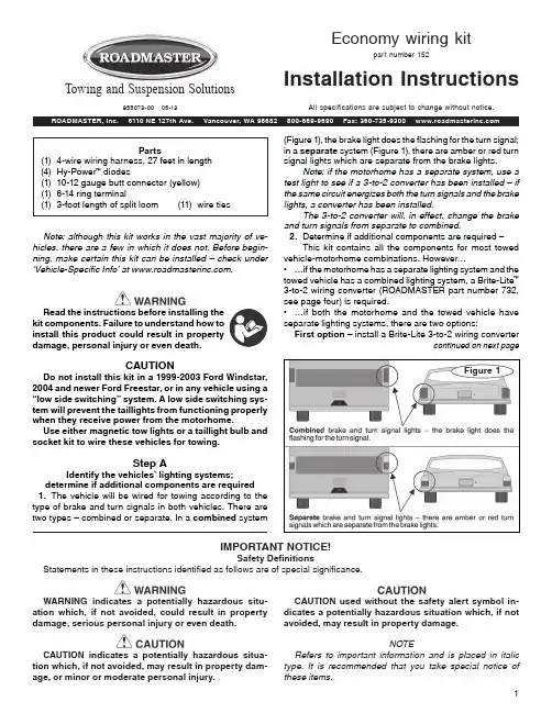
Parts(1) 4-wire wiring harness, 27 feet in length (4) Hy-Power ™ diodes(1) 10-12 gauge butt connector (yellow) (1) 6-14 ring terminal(1) 3-foot length of split loom (11) wire tiesNote: although this kit works in the vast majority of ve-hicles, there are a few in which it does not. Before begin-ning, make certain this kit can be installed — check under ‘Vehicle-Specific Info' at .Read the instructions before installing the kit components. Failure to understand how to install this product could result in property damage, personal injury or even death.CAUTIONDo not install this kit in a 1999-2003 Ford Windstar, 2004 and newer Ford Freestar, or in any vehicle using a “low side switching” system. A low side switching sys-tem will prevent the taillights from functioning properly when they receive power from the motorhome.Use either magnetic tow lights or a taillight bulb and socket kit to wire these vehicles for towing.Step AIdentify the vehicles' lighting systems;determine if additional components are required 1. The vehicle will be wired for towing according to the type of brake and turn signals in both vehicles. There are two types — combined or separate. In a combined system1IMPORTANT NOTICE!Safety DefinitionsStatements in these instructions identified as follows are of special significance. WARNING indicates a potentially hazardous situ-ation which, if not avoided, could result in property damage, serious personal injury or even death. CAUTION indicates a potentially hazardous situa-tion which, if not avoided, may result in property dam-age, or minor or moderate personal injury.CAUTION used without the safety alert symbol in-dicates a potentially hazardous situation which, if not avoided, may result in property damage.NOTERefers to important information and is placed in italic type. It is recommended that you take special notice of these items.(Figure 1), the brake light does the flashing for the turn signal; in a separate system (Figure 1), there are amber or red turn signal lights which are separate from the brake lights. Note: if the motorhome has a separate system, use a test light to see if a 3-to-2 converter has been installed — if the same circuit energizes both the turn signals and the brake lights, a converter has been installed.The 3-to-2 converter will, in effect, change the brake and turn signals from separate to combined.2. Determine if additional components are required — This kit contains all the components for most towed vehicle-motorhome combinations. However…• …if the motorhome has a separate lighting system and the towed vehicle has a combined lighting system, a Brite-Lite ™ 3-to-2 wiring converter (ROADMASTER part number 732, see page four) is required.• …if both the motorhome and the towed vehicle have separate lighting systems, there are two options:First option — install a Brite-Lite 3-to-2 wiring convertercontinued on next pageFigure 1Economy wiring kitpart number 152Installation InstructionsAll specifications are subject to change without notice.Towing and Suspension Solutions 855073-00 05-13be necessary to remove the taillight assemblies from the exterior of the vehicle to gain access to the wiring.)2. With a circuit tester, identify the brake light, taillight and turn signal wiring.3. Wire the diodes according to the appropriate schematic (on page three) that matches your combination of vehicles.4. Use the brown wire you saved in step C4 to jump the diodes attached to the taillights, as shown in the schemat-ics. Note: use the yellow female spade connector on the diode you will use to jump the brown wire.5. Use the included ring terminal and a self-tapping screw (not included) to attach the ground wire.Note: to avoid grounding problems, attach the wire to a good chassis ground, preferably directly to the frame.CAUTIONRefer to the owner’s manual before attaching the ground wire. Some manufacturers stipulate that ground wires must be attached at specific locations.Significant damage to the vehicle’s electrical system, as well as other consequential, non-warranty damage will occur if the ground wire is not attached at one of these points.6. If it was necessary to drill a hole, seal it with silicone sealant after you have routed the wires through.Attach the diodes as close to the towed vehicle’s lights as possible, to avoid interaction with other cir-cuits which may be tied into the center brake light, the running lights, the turn signals or the brake light wires. Attaching the diodes farther away may cause the towed vehicle’s lights to work improperly, as well as cause damage to other electrical components in the vehicle. Failure to follow these instructions may result in property damage, personal injury or even death.CAUTIONFailure to attach the diodes as indicated in the wiring diagrams will create a backfeed through the vehicle’s electrical system, which will allow electrical current from the towed vehicle to disrupt one or both of the vehicles’ electrical systems.Additionally, if a supplemental braking system is installed it may not operate, or may only operate inter-mittently.Wire the towed vehicle according to the instructions above, and the appropriate schematic. Improperly wiring the towed vehicle may cause an electrical malfunction or other damage, which may result in property damage, personal injury or even death.7. Test each of the circuits to confirm that the lighting func-tions correctly.2continued from preceding page(part number 732) on the motorhome. Use the schematic labeled “Combined towed vehicle to separate motorhome” (on page three) to wire the vehicle.Second option — In order to maintain separate brake and turn signals, the power cord must have at least five circuits. There are a number of power cords available for this purpose, such as 7-to-6-wire Flexo Coil, part number 146-7 (see page four).Two additional diodes (part number 792, see page four) and one 10 ga. x .250 female spade connector are also required for this option.Step BAttach the wiring harness1. Attach one end of the wiring harness to the electrical socket at the front of the towed vehicle. Connect the wires according to the instructions that came with the electrical socket.Step CRoute the wiring harness1. The wiring harness will be routed to the rear of the vehicle, then split and attached to the back of both taillight assemblies. Before you begin, plan a route that avoids the possibility of fraying or melting the wiring against moving parts, sharp edges, the fuel lines or hot components. If the OEM wiring harness is accessible, plan a route alongside it.2. Route the wiring harness. Where appropriate, use a section of the included split loom to protect the wires; use one or more of the included wire ties to secure the wiring in place.Route the wiring harness to avoid moving parts, sharp edges, the fuel lines or hot components such as the engine or exhaust system.Wiring exposed by moving parts, sharp edges or hot components may cause a short circuit, which can result in damage to the vehicle’s electrical system as well as other, consequential damage.Wiring which is attached in close proximity to the fuel lines may ignite the fuel.Failure to follow these instructions may cause prop-erty damage, personal injury or even death.3. At the rear of the vehicle, find a suitable point to gain access to the vehicle’s taillights.4. Route the wiring harness to the closest taillight assembly and then over to the other taillight assembly.Trim the excess wiring. (Save the brown wire; you may use it in step D4.) Then separate the bonded wires in the harness and, depending on the lighting systems in both vehicles (see page three), peel back the appropriate wire(s) to the other side.Step DWire the vehicle for towing1.Expose the wires in both taillight assemblies. (It may3CAUTIONThe color codes listed below are the most commonly used. However, color coding is not standard with all manu-facturers.Use the color codes for initial reference only; confirm the function of each wire with a circuit tester.The towed vehicle's lighting system may not function, or function improperly, if the wires are not connectedcorrectly. Cross-wiring may also cause a short circuit, a blown fuse or other non-warranty damage.Wiring schematics4Hy-Power ™ diodesIf your combination of vehicles requires additional diodes, use Hy-Power diodes. They have a heavy-duty, powder-coated aluminum heat sink, and each diode is protected against the elements — all components are housed in-side an epoxy-sealed, powder-coated aluminum case. Includes detailed wiring instructions.790 one Hy-Power diode 792 two Hy-Power diodes 793 three Hy-Power diodes 794 four Hy-Power diodesBrite-Lite ™ 3-to-2 converterIf you have this — the motorhome has separate brake and turn signal lights; the towed ve-hicle has combined brake and turn signal lights.Then you need this — the Brite-Lite converter connects a vehicle with a separate brake and turn signal system to one with a combined brakeand turn system, while delivering more current to the towed vehicle’s brake and turn signals for brighter illumination.732Brite-Lite 3-to-2 wiring converterFlexo-Coil ™ power cordsThe wires in Flexo-Coil cords are water-, oil- and chemical-resistant, and the plugs are injected with silicone to prevent corrosion. They ex-pand to more than eight feet and conveniently contract for storage. Part number 146-7 — 7- to 6-wire cord with plugs, sockets and socket bracket Part number 164-7 — 7- to 4-wire cord with plugs, sockets and socket bracketStop pulling fuses to tow!How about if you never had to spend another minute with your face on the floor mat, gazing up into a black void, hunting for a miniscule piece of plastic playing hide and seek? You don’t have to.FuseMaster eliminates the necessity of having to remove a fuse for towing, then having to reinsert it for driving. After it’s installed you simply flip a switch to accomplish the same task.There are several FuseMasters which, collectively, fit most vehicles which must have fuses removed for towing. For the fit list, click the ‘Vehicle Specific Info’ tab at .Don't do the Fuse Limbo…76510 fits the majority of vehicles where a fuse must be pulled 76511 a longer version of the 7651076512 where two fuses are required to be removed 76513 use to replace a heavy-duty, 50-amp fuse76514 for the 2013 Chevrolet Traverse, Buick Enclave and GMC Acadia…Just flip a switch!Advertisement。

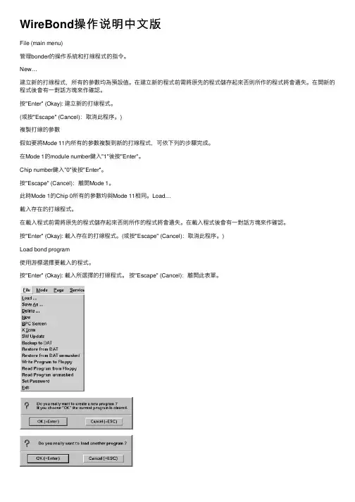
WireBond操作说明中⽂版File (main menu)管理bonder的操作系統和打線程式的指令。
New…建⽴新的打線程式,所有的參數均為預設值。
在建⽴新的程式前需將原先的程式儲存起來否則所作的程式將會遺失。
在開新的程式後會有⼀對話⽅塊來作確認。
按"Enter" (Okay): 建⽴新的打線程式。
(或按"Escape" (Cancel):取消此程序。
)複製打線的參數假如要將Mode 11內所有的參數複製到新的打線程式,可依下列的步驟完成。
在Mode 1的module number鍵⼊"1"後按"Enter"。
Chip number鍵⼊"0"後按"Enter"。
按"Escape" (Cancel):離開Mode 1。
此時Mode 1的Chip 0所有的參數均與Mode 11相同。
Load…載⼊存在的打線程式。
在載⼊程式前需將原先的程式儲存起來否則所作的程式將會遺失。
在載⼊程式後會有⼀對話⽅塊來作確認。
按"Enter" (Okay): 載⼊存在的打線程式。
(或按"Escape" (Cancel):取消此程序。
)Load bond program使⽤游標選擇要載⼊的程式。
按"Enter" (Okay): 載⼊所選擇的打線程式。
按"Escape" (Cancel):離開此表單。
Save as…儲存現在所使⽤的打線程式。
使⽤鍵盤輸⼊適合的程式名稱。
可輸⼊254個字,不可使⽤特殊字元。
若有相同的名稱,將發出⼀個對話⽅塊訊息來確認按"Enter" (Okay): 儲存檔案。
(或按"Escape" (Cancel):取消此程序。
) 按"Escape" (Cancel):離開此表單。
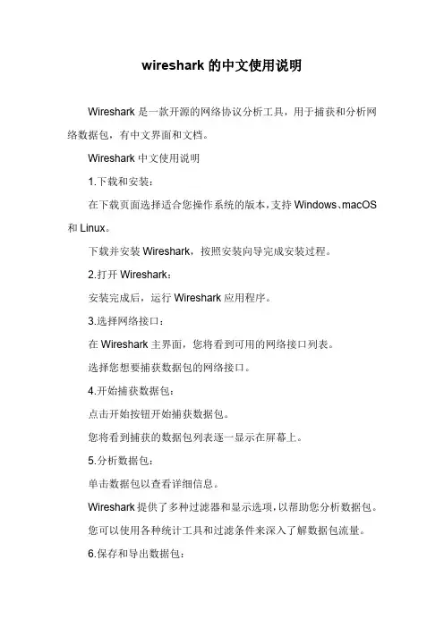
wireshark的中文使用说明Wireshark是一款开源的网络协议分析工具,用于捕获和分析网络数据包,有中文界面和文档。
Wireshark中文使用说明1.下载和安装:在下载页面选择适合您操作系统的版本,支持Windows、macOS 和Linux。
下载并安装Wireshark,按照安装向导完成安装过程。
2.打开Wireshark:安装完成后,运行Wireshark应用程序。
3.选择网络接口:在Wireshark主界面,您将看到可用的网络接口列表。
选择您想要捕获数据包的网络接口。
4.开始捕获数据包:点击开始按钮开始捕获数据包。
您将看到捕获的数据包列表逐一显示在屏幕上。
5.分析数据包:单击数据包以查看详细信息。
Wireshark提供了多种过滤器和显示选项,以帮助您分析数据包。
您可以使用各种统计工具和过滤条件来深入了解数据包流量。
6.保存和导出数据包:您可以将捕获的数据包保存到文件以供后续分析。
使用文件菜单中的导出选项将数据包导出为各种格式。
7.阅读文档:Wireshark提供了详细的用户手册,您可以在或应用程序中找到帮助文档。
在Wireshark中,您可以点击帮助菜单并选择Wireshark用户手册查看详细文档。
8.社区和支持:Wireshark社区提供了丰富的资源,包括用户论坛、教程和插件。
如果您遇到问题,可以在社区中寻求帮助。
Wireshark是一个功能强大的工具,可以用于网络故障排除、协议分析、网络安全等多个方面。
熟练掌握它需要时间和经验,但它提供了丰富的功能和强大的能力,以深入了解网络流量和问题。
希望这个简要的使用说明能够帮助您入门Wireshark的基本操作。
如果您需要更深入的信息和指导,建议查阅文档以及参与社区。

FLUID CONTROL DIVISIONParker Hannifin Corporation95 Edgewood AvenueNew Britain, CT 06051Telephone (860) 827-2300IOM HN01Fax (860) 827-2384(Rev 0812)Installation, Operating & Maintenance Instructions3-Way and 4-Way, Pilot Operated, Sealed Spool Solenoid Valves1/4" NPT & 1/2" NPTValve Types: U331N03, U331N04, U341N03, U341N04, U341N05,U342N03, U347N03GENERAL SAFETY INSTRUCTIONS BEFORE INSTALLATIONFAILURE OR IMPROPER SELECTION OR IMPROPER USE OF THE PRODUCTS AND/OR SYSTEMS DESCRIBED HEREIN OR RELATED ITEMS CAN CAUSE DEATH, PERSONAL INJURY AND PROPERTY DAMAGE.Both the conduit coil and hazardous coil contain a green “grounding” wire that must be secured to a proper ground location. DO NOT cut off the green ground wire. Doing so could negate a proper ground path and leave the valve assembly unprotected or “hot”.This document and other information from Parker Hannifin Corporation, its subsidiaries and authorized distributors provide product and/or system options for further investigation by users having technical expertise. It is important that you analyze all aspects of your application, including consequences of any failure, and review the information concerning the product or system in the current product catalog. Due to the variety of operating conditions and applications for these products or systems, the user, through its own analysis and testing, is solely responsible for making the final selection of the products and systems and assuring that all performance, safety and warning requirements of the application are met. Usage of the device in a manner that is contrary to these Operating Instructions or the application conditions and specification providedin the Catalog is improper and will void your warranty.The products described herein, including without limitation, product features, specifications, designs, availability and pricing, are subject to change by Parker Hannifin Corporation and its subsidiaries at any time without notice.Carefully read installation, operation and maintenance procedures prior to installing or servicing valve.Do not use valve as a safety shut-off valve when making repairs.Do not install a valve or attempt to repair a valve before depressurizing system down to atmospheric pressure and removing electrical voltage.Care must be taken to ensure the proper use of the valve and that the valve materials selected are suitable for the media being handled. Parker assumes no liability for damage caused by improper material selection in the case of corrosion from aggressive media.Caution: Do not, at any time, make any alteration or modifications to any valve without the express and written approval of Parker’s Fluid Control Division.DescriptionThese valves are pilot operated 2-position, 4 ported 3-way or 5 ported 4-way, and 3-position 5 ported 4-way, directional control, solenoid models. They are offered in anodized aluminum body construction. Valves may be ordered with either DIN or Conduit NEMA 2, 4, 4X integrated coils for ordinary locations or NEMA 7 and 9 for hazardous locations:Applicable StandardsFM CSADivisions I; Class I, Groups A, B, C, D Divisions I; Class I, Groups A, B, C, DDivisions II; Class I, Groups E, F, and G Divisions II; Class I, Groups E, F, and GClass 1, Zone 1, AEx m II T4 Class 1, Zone 1, Ex m II T4The spool valves comprise a standard locking manual override providing operation without electrical supply.The spool valves are offered with the following standard features:-In line pilot for a low profile-22mm DIN pilot for direct mounting in non-explosive environments.-Both Conduit and Hazardous pilots for NEMA rated and explosive environments. Mounting plate required for NEMA rated coils.-High Nominal Flow-Cv 1.2 for 1/4” valves or 1250Nl/mn-Cv 3.0 for 1/2” valves or 3000Nl/mn-Standard Fluid temperature 14°F (-10°C) to 122°F (50°C)-Single Solenoid electrically operated, combined spring & pneumatic return (U331 & U341 series)-Dual Solenoid (Bistable) electrically operated, with neutral position return closed (U342 series)-Dual Solenoid (Bistable) electrically operated, air-solenoid return (U347 series)Principles of Operation – Connection of the NAMUR spool valve3-Way ValvesThe valve is piped to a single acting spring return cylinder as follows: Supply air pressure is applied at the inlet port 1. When de-energized, the valve inlet port 1 is closed and valve cylinder port 2 is open to the valve exhaust port 3. The cylinder is in the retracted state.When the coil is energized, pressure is applied from the valve inlet port 1 to the valve cylinder port 2 forcing the cylinder open and exhausting air behind the piston to the valve exhaust port 3. The cylinder is in the extended state.4-Way ValvesThe valve is piped to a double acting cylinder as follows: Supply air pressure is applied at the valve inlet port 1. Valve port 2 is open to one port of the cylinder while valve port 4 is open to the other port of the cylinder. The solenoid valve functions in such a way that pressure is applied to either side of the piston in the cylinder, and exhausted out of the opposite side of the pressurized cylinder.When de-energized, the supply air pressure port 1 is open to the valve port 2, valve port 4 is open to valve exhaust port 5, and valve exhaust port 3 is isolated by seals on the spool. The pilot valve orifice is sealed by the insert in the plunger. The pilot valve exhaust port is open to the valve piston assembly and atmosphere.When energized, the valve inlet port 1 is open to port 4, as well as between valve port 2 and valve exhaust port 3. The spool and seals seal valve exhaust port 5. This allows pressure to be applied to other side of the piston in the cylinder, causing the piston to move, and exhaust the fluid on the other side of the piston of the cylinder into port 2, through the valve and out of valve exhaust port 3.Manual OverridesManual override - The unit is shipped with a latching manual override. For a latching override, apply force to the slotted screw component, turn clockwise to lock. To unlock, turn counterclockwise.Fluid CodesListed below are the common fluid codes The codes for the approved fluids for use with each valve are printed on the outside of the individual packaging.CODE FLUIDA- Air or non-toxic, nonflammable gasesFor the maximum fluid temperatures, as well as valve ambient temperature limitations, check the valve part number on the nameplate and refer to the catalog.Installation InstructionsPrior to installing the solenoid valve, depressurize the pipes and clean them internally to avoid particles entering theMounting position and pressure limits:Valve with DIN Coil:Mount the valve directly on the actuator with the (2) M5 thread screws provided for the 1/4" valve and with the (2) M6 thread screws for the 1/2" valve. Torque to 35 to 45 in-lbs (4 to 5 Nm). Make sure the O-rings and locating pin are assembled to the bottom of the valve prior to mounting the valve for correct positioning on the actuator. Do not use the sleeve or enclosure as a lever when applying torque.Valve with Conduit or Hazardous Coil: (see next paragraph for valve model U341N05 only)The conduit and hazardous coils require the use of a mounting plate kit due to the increased coil width. The mounting plate kit consists of the aluminum mounting/spacer plate, 2 O-rings and 2 longer screws. The valve model number U341N05 containing the 3/2, 5/2 conversion plate does not require a separate mounting kit (see next paragraph). Make sure the O-rings are assembled to the bottom of the valve before positioning the valve over the mounting/spacer plate. Make sure that the O-rings and the locating pin are assembled to the bottom of the mounting/spacer plate prior to mounting the valve onto the actuator. Use the 2 longer screws to mount the valve to the actuator. Torque to 35 to 45 in-lbs (4 to 5 Nm). Do not use the sleeve or enclosure as a lever when applying torque.Valve model U341N05 with conversion plate:With the U341N05 valve, the 3/2, 5/2 conversion plate also functions as the mounting/spacer plate for the conduit and hazardous coils. Make sure that the gasket surface with the function indicator tab is assembled toward the bottom of the valve body. The indicator tab will point toward the schematic on the top of the valve body indicating the valve function. To change the valve function, rotate the conversion plate 180 degrees keeping the gasket face toward the vale body. The O-rings and the locating pin are assembled to the bottom of the conversion plate prior to mounting the valve onto the actuator. Use the 2 of the included screws to mount the valve to the actuator. Torque to 35 to 45 in-lbs (4 to 5 Nm). Do not use the sleeve or enclosure as a lever when applying torque.The valves are multi-poised and will perform properly when mounted in any position. However, for optimum life and performance, the valves should be mounted with the spool in the vertical position to minimize wear and reduce the possibility of foreign matter accumulating inside the sleeve and spool area.Line pressure must conform to nameplate rating.Valve Piping: Correctly support and align pipes to prevent mechanical strain on the valve. Connect line pressure to the inlet port. Use of tape sealant, thread compound or sealants is permissible, but should be applied sparingly to male pipe threads only. To avoid damage to the equipment, DO NOT OVERTIGHTEN pipe connections.Media filtration: Normally, filtration is not required, but dirt or foreign material in the media may cause excessive leakage, wear, or in exceptional cases, malfunction. The valves do include a 40 micron internal pilot filter to help prevent clogging of the pilot orifice. If additional filtration is used, install the filter on the inlet side as close to the valve as possible. Clean periodically depending on service conditions.Lubrication: Lubrication is not required.ELECTRICAL CONNECTIONSGeneral Recommendations and Safety Precautions- Electrical connection must be made by qualified personnel using standard electrical practices in compliance with local authorities and the National Electrical Code.- Depending on the voltage, electrical components must be grounded according to local standards and regulations- Most valves are designed for continuous duty. To prevent the risk of personal injury, do not touch the solenoid operator which can become hot under normal operating conditions.-The solenoid coil must be assembled to the valve sleeve operator for proper valve operation. Failure to assemble the coil to the valve before applying system voltage will permanently damage the coil within a short period of time.- Electrical supply must conform to nameplate rating.Hazardous Location Coil WARNING: Valves to be installed in Hazardous Locations, must be outfitted with Hazardous Location coils only. Verify nameplate data and coil part number before installing the valve.A surge protector corresponding to the coil’s rated current or a motor safety switch with instantenous short circuit or thermal cutout (set at rated current) has to be pre-connected for each solenoid coil as a short circuit cutout. The surge protector may be positioned in the respective power supply unit or it must be pre-connected separately.W ARNING:Turn off electrical power before connecting the valve to the power source.If the coil assembly is located in an inconvenient orientation, it may be reoriented to facilitate installation. Loosen coil assembly nut, rotate coil assembly in 45° increments to desired position, and then retighten the nut with an input torque of 4.0 to 5.0 in-lbs. [0,5 Nm].DIN Coil (ND1x) and various cable option terminations: Electrical connection is made with detachable DIN 43650 B plug connector for cable dia. 6-8mm (Pg9), rotatable by 180° increments (3 pins: 2 + earth ground pin). Loosen cable screw and remove plastic housing from DIN coil. Do not remove the gasket from the DIN spades on the coil. Separate the plastic block from the housing with a small screwdriver to expose the elecctrical terminations. Feed the lead wires through the conduit hub and attach them to the appropriate screw terminal. For electrical connection within the terminal box, use field wire that is rated for 90o C or greater. Snap the plastic block back into place inside the metal enclosure. Replace the cover and hand-tighten the cover screws. Place the gasket over the DIN spades on the coil and press the terminal box and coil together. Secure the terminal box to the coil using the mounting screw provided.Slide one o-ring over and down the sleeve assembly until the o-ring rests on the valve body., Slide the DIN coil over the valve sleeve. Affix nut to sleeve and tighten between 4.0 to 5.0 in-lbs. [0,5 Nm] torque.Conduit Coil (NC1x) with 1/2” NPT connection: Conduit coils meeting NEMA 2, 4, 4X integrated coils for ordinary locations. Use suitable electrical cabling and conduit materials and components meeting applicable NEMA recommendations.Hazardous Coil (NH1x) with 1/2” NPT connection: Hazardous coils meeting NEMA 7, and 9: Divisions I and II; Class I, Groups A, B, C, and D; Class II, Groups E, F, and G. Use suitable electrical cabling and conduit materials and components meeting applicable NEMA recommendations.Coil/enclosure temperature: Standard valves are supplied with coils designed for continuous duty service. Normal free space must be provided for proper ventilation. When the coil is energized continuously for long periods of time, the coil assembly will become hot. The coil is designed to operate permanently under these conditions. Any excessive heating will be indicated by smoking and/or odor of burning coil insulation.For the maximum valve ambient conditions, as well as the fluid temperatures, check the valve part number on the nameplate and refer to the catalog to determine the maximum temperatures.MAINTENANCEPrior any maintenance work, switch off power supply, depressurise and vent the valve to prevent the risk of personal∙Preventive maintenanceValve should be exercised (cycled from de-energized to energized position several times) if stored in inventory or if inactive for a lengthy period of time (more than a month).Avoid obstruction of exhaust port when it is not connected or protect it with a cap.∙CleaningMaintenance of the valve depends on the operating conditions. They must be cleaned at regular intervals. Cleaning must be done when a slowing down of the cycle, a leakage or an abnormal noise is noticed. The components must be checked for excessive wear.Note: Depending on service conditions, filtration, and lubrication, it may be required to periodically clean and/or replace worn components.C AUTION:Do not expose plastic or elastomeric materials to any type of commercial cleaning fluid. Parts should be cleaned with a mild soap and water solution.Monostable in line Miniature pilot Bistable Miniature pilot O-ring 10O-ring 9Screws 8Under Seat Flow Path 7Pin6“Bug”cap 5Operator Sleeve 4Manual Override 3O-ring11Pilot Top Plate 2Pilot Body 1DescriptionItemPilot ValveCross Section ViewConversion PlateHazardous or Conduit Coil U331N03, U331N04 13551331524 3154 2Trouble ShootingSymptom Procedure 1. Valve fails to operate or is sluggish. 1. Check electrical supply with voltmeter. Voltage must agreewith coil rating.2. Check coil with ohmmeter for shorted or open coil.3. Make sure that pressure complies with pressure ratingmarked on valve. Pressure must not be less than minimumoperating pressure.4. Inspect for contamination in ports. Remove debris if found.Check filter in main body, clean or replace if necessary.5. Verify that the sleeve assembly and plunger spring are notdamaged.* Remove the 4 screws and gently lift off the pilot sectionof the valve. Take care not to lose the o-rings andinternal components.* Remove the top plate. Lift out and inspect the sleeve,plunger, rubber disk and spring for debris or damage.Replace sleeve assembly, top plate and 4 screws.* Make sure the manual override stem is located on theported side of the valve body.2. External leakage at sleeve flange to body joint or pilot section to main body joint. 1. Check the 4 screws are tight but do not apply excessive forceto damage the plastic plate.2. If leakage persists, remove sleeve and check flange ando-ring seals for damage. Refer to step 5 above for disassembly.。

X4简体中文用户指南欢迎使用包装内容 2充电/电池状态 3配对 5找到舒适佩戴搭配 7选择您的设置 7耳挂式佩戴 8耳塞式佩戴 11详细说明按钮功能 14 Jaybird 应用程序 17多点功能 - 连接多设备 18智能手表 19疑难解答 20规格参数 21质保、警告和安全性 22欢迎使用安装或使用产品之前,请参阅安全警告以获取重要的产品安全信息。
JAYBIRD X4坚固,多功能自在奔跑获取详细视频说明,请访问 /support/约8小时播放时间防汗防水 (IPX7)运动贴合 - 稳固舒适10 分钟充电 ≈ 1 小时播放时间快调线夹出色音质,可个性化定制你的运动音效音乐 & 通话集成 USB 充电托架便携袋硅胶耳套(尺寸 1 / 2 / 3)包装内容充电/电池状态我们建议使用 5V 500mA 的 USB 电源为耳机充电。
供电电压超过 5.5 伏特的墙面/车载适配器/充电器会损坏您的 Jaybird 耳机,请勿使用。
2 小时充电可获得 约8 小时播放时间。
10 分钟充电可获得 约1 小时播放时间。
充电/电池状态每次开启耳机时,您都可以听到电池电量提示。
电池电量提示会将剩余电量值四舍五入至最接近的 20%。
手机和 Jaybird 应用程序同样可以显示电池电量。
Jaybird 应用程序能以 1% 的精度显示电池电量。
配对配对,请按住中央按钮直至 LED耳机关闭后,请重复上述 X4找到舒适佩戴搭配1. 安装耳翼找到舒适佩戴搭配2. 找到合适尺寸的耳套和耳翼找到舒适佩戴搭配3. 快调线夹快调线夹可使耳机线不触碰颈部和肩部,尤其适合于耳挂式佩戴。
找到舒适佩戴搭配1. 找到合适尺寸的耳套和耳翼找到舒适佩戴搭配2.衬衫夹可使用衬衫夹将 X4耳机固定到衬衫后领口处。
详细说明按钮功能开/关开启耳机:按住中央按钮直至听到音调上升的“电源开启”声音提示并且 LED 闪烁绿色。
关闭耳机:按住中央按钮直至听到音调下降的“电源关闭”声音提示并且 LED 在关机前亮起红色。
求生之路4怎么操作方法
《求生之路4》是一款团队合作的第一人称射击游戏,玩家需要与其他玩家组队合作,共同对抗大量的感染者(僵尸)。
基本操作方法如下:
移动:WASD键或方向键操控角色的移动方向。
瞄准:鼠标控制角色的视角,通过移动鼠标来瞄准。
射击:鼠标左键进行射击,按住不动可连续射击。
换武器:滚动鼠标滚轮或按下数字键1-5来切换不同的武器。
你可以在地图上找到额外的武器供你选择。
再装填:R键重新装填当前武器的弹药。
拾取道具:走到道具旁边按下E键拾取。
治疗队友:按下F键可以治疗受伤的队友。
投掷物品:用鼠标右键可以投掷道具,比如炸弹或药品。
技能:每个角色都有自己的技能,按下左ALT键可以使用你的角色技能。
与队友交互:在游戏中,你需要与队友密切合作,比如救援受伤的队友或者协作解决问题等。
通过按下E键与队友进行交互。
这些只是《求生之路4》的一些基本操作方法,游戏中还有更多的细节需要你去探索和应对。
多和队友合作,留意游戏中的敌人和任务目标,才能在游戏中获得胜利。
网络综合控制键盘H.265 Network Integrated Control Keyboard使用说明书Operation Instruction(中文版V2.0)Copyright 2003-2018.All Rights Reserved.温馨提示:感谢您使用本公司产品。
为了让您能够尽快熟练的操作本机,请您仔细阅读我们为您配备内容详细的使用说明书,从中您可以获取有关产品安全注意事项、产品介绍以及产品使用方法等方面的知识。
当您阅读完说明书后,请将它妥善保存好,以备日后参考。
如果您在产品的使用过程中发现什么问题,请联系产品技术服务人员。
谢谢您的合作!申明:在编写此说明书时我们非常小心谨慎,并认为此说明书中所提供的信息是正确可靠的,然而难免会有错误和疏漏之处,请您多加包涵并热切欢迎您的指正。
但是我们将不对本手册可能出现的问题和疏漏负责。
同时,由于我们无法控制用户对本手册可能造成的误解,因此,将不负责在使用本手册的过程中出现的事故或由此引起的损坏。
对于因使用本产品所造成的任何损坏第三方的索赔不负责任。
对于因软件的误操作、产品维修、或其它意外情况等引起资料的删改或丢失不负任何责任,也不对由此造成的其它间接损失负责。
本产品的发行和销售由原始购买者在许可协议条款下使用。
未经允许,任何单位和个人不得将本说明书全部或部分复制、再生或翻译成其它机器可读形式的电子媒介。
本说明书若有任何修改恕不另行通知。
因软件版本升级而造成的与本说明书不符,以软件为准。
注:本设备在出厂前已经过严格的质量测试,符合国家电磁辐射标准。
目录第一章概述 (5)1 设备概述 (5)2 设备功能 (5)2.1 解码功能 (5)2.2 视频输出 (6)2.3 报警(选配) (6)2.4 USB接口 (6)2.5 其它 (7)3 规格参数 (7)4 连接示意图 (8)第二章键盘结构及说明 (8)1 键盘控制器面板图 (8)1.1 按键盘输入区 (9)1.2、主操作区 (9)1.3、PTZ及前端控制区 (9)1.4、播放操作区 (9)1.5、功能键区 (9)1.6、飞梭 (9)1.7、显示屏 (10)1.8、摇杆 (10)1.9、键盘指示灯 (10)2 键盘后背板 (11)3 鼠标操作控制键盘 (11)第三章键盘基本操作 (11)1 出厂默认值 (11)1.1 默认IP 址 (11)1.2 默认用户名密码 (11)2 按键选择及功能基本操作 (12)2.1、快捷键 (12)2.2、控制界面与视频解码输出切换 (12)3 文字输入及基本操作 (12)第四章键盘功能性操作 (13)1 开机登陆 (13)2 主操作界面 (13)3 主菜单 (14)4 键盘设置 (14)4.1网络设置 (15)4.2 串口设置 (15)4.3 系统设置 (16)4.4 时间设置 (16)4.5 输出显示设置 (17)4.6 重启 (17)4.7 升级 (18)4.8 注册授权 (18)4.9恢复出厂值 (19)4.10系统维护 (19)4.11 版本 (20)5 用户管理 (20)6 设备管理 (21)6.1 音频管理 (22)6.2 多通道输入设备管理 (22)6.3 解码设备管理及控制 (23)6.4 摄像机管理 (25)第五章解码、控制与输出操作 (29)1 显示屏与HDMI输出口的关系 (29)2 初始化 (29)3 输入提示 (30)4分割 (31)4.1选中窗口 (31)4.2分割 (32)5 拼接 (32)6 输入输出对应 (33)7 全屏拼接 (33)8 模式管理 (34)9 设置输入源窗口轮巡 (35)10 模式组轮巡 (36)11 更改窗口号 (37)12 摇杆及按键PTZ操作(云台、镜头等操作) (37)13 鼠标操作PTZ (38)14 显示视频 (38)15 启动轮巡 (38)16 录像要回放 (38)第六章常见问答 (39)1、模式及模式管理是什么意思 (39)2、输入正确的用户名密码后不能登陆 (39)3、在进行PTZ操作时,不能正常控制 (39)4、数字键盘如何一键启动或停止模式组轮巡 (39)5、用数字键盘管理矩阵时,无法删除已添加的矩阵 (39)6、键盘自带屏如何显示画面与HDMI输出口关系 (39)网络综合控制键盘Network Integrated Control Keyboard第一章概述1 设备概述网络综合控制键盘(以下简称键盘)是以操作控制安防监控主机、智能摄像机、数字录像机、报警主机为特色的操作设备。
Wireshark使用说明文档(详细中文版)前言:由于wireshark在网上的使用说明文档较少,并且在我们的日常的工作中该软件基本每天都要接触,因此写下该文档,只希望对该软件有兴趣的同学的学习能稍微有一点点的帮助。
该文档的出现完全要感谢我们的部门经理,要不是他的督促下可能到现在仍然没有类似的介绍wireshark的文档出现。
由于每天的事情也比较多最近,以至于该文档拖了很久才出现在大家面前,对此也深感无奈;`该文档只介绍wireshark的一些简单的、常用的日常使用的方式,由于书写者水平有限,致以该文档在书写的过程中可能避免不了会有一些错误以及不准确的地方,对于错误的、不准确的地方还请大家多多指正、多多包涵。
中新软件有限公司技术中心:孙凯目录简介 -------------------------------------------------------------------------------------------------------------------------------------- 31.1.、什么是Wireshark----------------------------------------------------------------------------------------------------- 32.1、主要应用--------------------------------------------------------------------------------------------------------------- 31.1.2. 特性 ------------------------------------------------------------------------------------------------------------- 4 安装 -------------------------------------------------------------------------------------------------------------------------------------- 42.1、windows平台上的安装 ------------------------------------------------------------------------------------------------ 42.2、linux平台上的安装 -------------------------------------------------------------------------------------------------- 112.2.1、RedHat版本---------------------------------------------------------------------------------------------------- 112.2.1.1、tcpdump源码安装方式 ---------------------------------------------------------------------------- 112.2.2.2、Linux yum安装方式 ------------------------------------------------------------------------------- 162.3、Ubuntu apt-get安装方式 ------------------------------------------------------------------------------------------ 21 界面概括 ------------------------------------------------------------------------------------------------------------------------------- 253.1.0、主菜单栏-------------------------------------------------------------------------------------------------------------- 263.1.1、抓包工具栏----------------------------------------------------------------------------------------------------------- 263.1.2、文件工具栏----------------------------------------------------------------------------------------------------------- 373.1.3、包查找工具栏-------------------------------------------------------------------------------------------------------- 383.1.4、颜色定义工具栏 ---------------------------------------------------------------------------------------------------- 383.1.5、字体大小工具栏 ---------------------------------------------------------------------------------------------------- 393.1.6、首选项工具栏-------------------------------------------------------------------------------------------------------- 39 菜单简介 ------------------------------------------------------------------------------------------------------------------------------- 444.2.0、菜单栏----------------------------------------------------------------------------------------------------------------- 444.2.1、file菜单 ------------------------------------------------------------------------------------------------------------- 454.2.2、Edit菜单 ------------------------------------------------------------------------------------------------------------- 464.2.3、View菜单 ------------------------------------------------------------------------------------------------------------- 494.2.4、Go菜单栏 ------------------------------------------------------------------------------------------------------------- 534.2.5、Capture菜单栏 ----------------------------------------------------------------------------------------------------- 544.2.6、Analyze菜单栏 ----------------------------------------------------------------------------------------------------- 554.2.7、Statistics菜单栏 ------------------------------------------------------------------------------------------------ 624.2.8、Telephony菜单栏 -------------------------------------------------------------------------------------------------- 704.2.9、Tools菜单栏 -------------------------------------------------------------------------------------------------------- 714.3.0、Internals(内部)菜单栏 -------------------------------------------------------------------------------------- 714.3.1、Help菜单栏---------------------------------------------------------------------------------------------------------- 72 wireshark显示/抓包过滤器 ----------------------------------------------------------------------------------------------------- 745.1、显示过滤器概括-------------------------------------------------------------------------------------------------------- 745.1.1、wireshark规则编辑----------------------------------------------------------------------------------------- 755.1.2、语法以及连接符 ---------------------------------------------------------------------------------------------- 765.1.3、新建规则-------------------------------------------------------------------------------------------------------- 765.2、抓包过滤器概括-------------------------------------------------------------------------------------------------------- 835.2.1、wireshark规则编辑----------------------------------------------------------------------------------------- 845.2.2、语法以及连接符 ---------------------------------------------------------------------------------------------- 845.2.3、新建规则-------------------------------------------------------------------------------------------------------- 85 协议分析 ------------------------------------------------------------------------------------------------------------------------------- 906.1、TCP协议原理简介及分析-------------------------------------------------------------------------------------------- 906.1.1、TCP协议原理简介-------------------------------------------------------------------------------------------- 916.1.2、TCP协议数据包捕捉分析 ---------------------------------------------------------------------------------- 976.1.2.1、TCP数据包头部格式 ------------------------------------------------------------------------------- 976.1.2.2、TCP连接建立的三次握手 ------------------------------------------------------------------------- 996.1.2.3、TCP四次挥手的连接终止 ----------------------------------------------------------------------- 1006.1.2.4、SYN Flood攻击数据包 -------------------------------------------------------------------------- 1016.1.2.5、ACK Flood攻击------------------------------------------------------------------------------------ 1016.2、HTTP协议原理简介及分析 ---------------------------------------------------------------------------------------- 1026.2.1、HTTP协议工作原理简介 ---------------------------------------------------------------------------------- 1036.2.2、HTTP协议数据包捕捉分析------------------------------------------------------------------------------- 1106.2.2.1、HTTP数据包头部格式---------------------------------------------------------------------------- 1106.2.2.2、HTTP协议的连接 ---------------------------------------------------------------------------------- 111 常见问题 ----------------------------------------------------------------------------------------------------------------------------- 1137.1、wireshark安装问题 ------------------------------------------------------------------------------------------------ 1137.1.2、找不到接口 -------------------------------------------------------------------------------------------------- 1137.2、wireshark显示问题 ------------------------------------------------------------------------------------------------ 1157.2.1、数据包序列号问题 ----------------------------------------------------------------------------------------- 1157.2.2、校验和问题 -------------------------------------------------------------------------------------------------- 116简介1.1.、什么是WiresharkWireshark 是网络包分析工具。
猎杀潜航4中文版(附操作配置攻略)喜爱二战题材游戏的玩家一定对《猎杀潜航》系列游戏有或多或少的接触。
1996年著名的战争游戏制作公司Strategic Simulations Inc.(SSI)推出了《猎杀潜航》(Silent Hunter),让众多玩家感受到了由电脑硬件性能与游戏制作水平的提高所带来的真实的潜战体验。
这款游戏一面世,就以其丰富逼真的模拟特性和声光效果而大受欢迎,被美国《PC Gamer》杂志评选为“有史以来最佳50款电脑游戏”之一,还获得美国“Computer Gaming World”的最佳模拟类游戏提名等各种奖项。
游戏介绍猎杀潜航4中玩家扮演一名美国潜艇舰长,率领一队船员驶向太平洋深海。
玩家将从事对敌作战、管理手下的船员等等任务。
本作的画面和声音表现与前作相比又有极大的提高。
前作以德国U型潜舰为仿真对象,而这代则将战场转移到了1941~1945的二战太平洋战场,玩家将扮演一名美国海军的潜艇指挥官,用鱼雷摧毁日军的海上运输线,而护卫航线的则是日本精锐的皇家海军,他们会击沉一切视野内美军舰船。
在游戏里玩家可以驾驶美国海军的P级、 Tambor, Salmon 和Gato等6种潜艇,而武器装备也将符合当时的真实情况,极高的拟真度,绝对可以让您过足深海下威风凛凛潜艇舰长的瘾,不管是寂静深海下静肃地以鱼雷偷袭或是浮出水面以舰炮突击,神出鬼没战术全赖您运筹帷幄!操作指南操作键1)一般按键F1控制室画面F2潜望镜画面F3目标方位传送器画面F4舰桥画面ALTF4甲板大炮画面>F5航海图画面F6鱼雷资料电脑(TDC)画面F7仪表板画面F8状态/损害控制室画面F9雷达画面F10航海日志+增快时间速率减缓时间速率ENTER回到正常的时间速率0完全停止1...5引擎前进动力由1/3到最高出力6...9引擎后退动力由1/3到紧急后退→尾舵向右←尾舵向左↑水平翼向上(上浮)↓水平翼向下(下沈)5(九宫数字盘)水平航行B释放压缩空气舱(紧急浮出水面)S浮出水面P航行至潜望镜深度C急速潜航H改变航向并对准目前的视野V改变视野并对准目前的航向R航行至雷达深度后退键重覆最后一则讯息ALT1...0发射1到10号鱼雷管中的鱼雷ALTD开启「设定精细度」的画面ALTT将视野盯住目前锁定的船舰ALTS开启或关闭SJ海面搜索雷达ALTA开启或关闭SD空中搜索雷达ALTP升降潜望镜ALTQ回到DOSALTG甲板大炮切换为手动/自动ALTO开启选项(Options)画面(可在此储存军旅生涯的游戏进度)ESC放弃任务/终止巡航航海图画面Z拉近焦距X拉远焦距目标方位传送器或潜望镜画面空白键选择/取消目标Z缩放焦距T切换到鱼雷资料电脑的画面N切换到仪表板的画面<向左转>向右转电池的使用为了能让电池充电,潜艇必须先浮出海面并以标准(或较低)的速度航行。
引言:概述:霍尼韦尔X4是一款多功能设备,旨在提供高效、便捷的操作体验。
它具备多种功能,包括X、X、X等。
在正文中,我们将详细介绍如何使用这些功能,并提供相关注意事项。
正文内容:I.启动和关机1.按下电源按钮启动霍尼韦尔X4。
2.等待设备启动完成并显示主界面。
3.在主界面上,关机按钮以正确关机设备。
II.菜单导航1.使用触控屏幕上的手指滑动来浏览菜单选项。
2.菜单选项以打开相应的菜单。
3.在菜单内,使用手指滑动以查看更多选项。
4.返回按钮以返回上一级菜单。
III.功能使用1.X功能a.进入X菜单,相关选项。
b.遵循屏幕上的指示进行进一步操作。
c.在完成后,确认按钮以提交操作。
2.X功能a.进入X菜单,选择相关选项。
b.根据需要,设置相关参数。
c.开始按钮以启动X功能。
3.X功能a.进入X菜单,选择相关选项。
b.启动相关传感器并进行校准。
c.在完成后,确认按钮以提交操作。
4.X功能a.进入X菜单,选择相关选项。
b.设置相关参数并启动功能。
c.在完成后,确认按钮以提交操作。
5.X功能a.进入X菜单,选择相关选项。
b.按照屏幕上的指示进行相关操作。
c.在需要时,保存按钮以保存操作结果。
注意事项:1.在使用霍尼韦尔X4之前,确保已经详细阅读设备的用户手册,了解相关安全注意事项和操作指南。
2.在使用设备时,遵循所有操作规程和安全标准,以确保使用过程安全可靠。
3.在设备操作过程中,如遇到任何异常情况或故障,请立即停止使用,并联系专业维修人员进行处理。
4.定期对设备进行维护和保养,以保持其良好的性能和使用寿命。
5.避免在恶劣的环境条件下使用霍尼韦尔X4,避免水、泥浆等有害物质进入设备。
总结:。
威迅威迅((德国德国))激光技术研发工业有限公司激光技术研发工业有限公司LWI IV激光焊机激光焊机((钢线钢线))SCT 线控延伸部分线控延伸部分设备外观图(关盖)设备外观图(开盖)可调式座椅刹车固定器1.气体钢瓶满载表2.限流指示表3.钢瓶固定带事故紧急停止钮参数编程钥匙主开关F1 按键A 打磨和焊接参数转换钮B 按住F1键同按下转黑色旋钮,接着旋转旋钮调整钢线直径 F2 按键按下F2键后,左边滑块恢复到标准状态。
这个可以使滑块到达所需位置LED 灯指示PWR 焊接控制器(WIRE JIG )电源如果正常,灯光常亮 Rot 数据传输时,指示灯闪动 WP 气体喷嘴位于焊接位置 LP 气体喷嘴不在焊接位置Menue Seta) 在WireJig 菜单中:按Menue/Set 键------ 按键可使按气体喷嘴前后移动 b) 在激光菜单中:可转换至参数界面或服务菜单 c) Clear/Del.:启动 Tara- Funktion按压按压旋钮旋钮旋钮::1) 按压旋钮至Wirejig 菜单a)持续按旋钮3秒钟以上,可在正负范围内调节激光能量b)短时间按压旋钮启动自动接力测试系统 (再按一次旋钮结束测试)2) 按旋钮至激光菜单在激光菜单中使用旋钮来选择各项子目录旋转旋钮旋转旋钮::1) 进入 Jig – 菜单在 Jig 菜单中,可通过旋转旋钮使滑具向转向方向移动 (在挂紧弹簧的情况下)2) 进入Laser- 菜单在Laser 菜单中可设置参数,带有指针功能- 并副有图片(可通过按压旋钮来选择)WireJig 操作界面操作界面0)目录1)钢线直径选择目录以及工作状态就绪显示 a) 打磨 shaping b) 焊接 welding2)最后一次激光波的能量显示部分 3)当前电动机位置(0-4000 之间) 4)当断线两端相接触后,精调计数器 5)归零6)拉力测试显示部分 7)拉力测试图像显示 8)工作状态显示行其它显示:伺服驱动:Rough Adjust粗调准Fine Adjust精调准Fine count 精计数拉力测试:TARA active Man/Auto归零Auto Tensile-Test running测试进行中 Auto Tensile-Test holding测试中断Auto Tensile-Test ready 测试结果激光焊激光焊接在切割线中的使用说明接在切割线中的使用说明接在切割线中的使用说明注意注意::该设备只允许在双手洁净的情况下使用!使用步骤:1. 钢线应该事先用砂纸打磨(不允许有切割液存在!可用工业酒精或者丙酮擦拭)2. 钢线用一个电子钳剪切电子钳平面侧为切割外缘 3. 用1000号的砂纸打磨钢线 4. 钢线穿过专用玻璃管5. 按下F2键→ 使玻璃管穿过固定凹槽6. 打开右侧螺栓,玻璃管推入导槽(并要保证凹槽清洁,可使用清洁喷剂)直到玻璃管放置到底7. 带有钢线的玻璃管被推到右测的凹槽里,用指甲轻柔推到最里位置8. 夹具盖被盖在右侧小车上,后拧螺栓(松紧适度)9. 钢线的末端大概长于玻璃管端0,5mm。