HSM6-12环网箱首选红申集团(意大利)控股有限公司
- 格式:pdf
- 大小:880.94 KB
- 文档页数:11

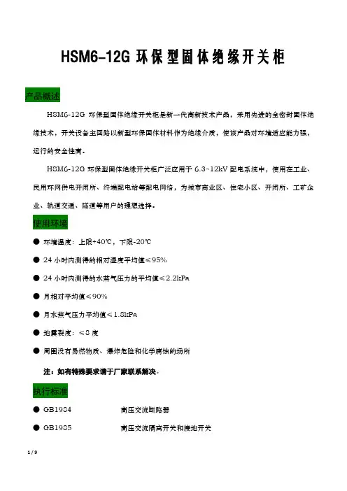
HSM6-12G环保型固体绝缘开关柜产品概述HSM6-12G环保型固体绝缘开关柜是新一代高新技术产品,采用先进的全密封固体绝缘技术,开关设备主回路以新型环保固体材料作为绝缘介质,使该产品对环境适应能力强,运行的安全性高。
HSM6-12G环保型固体绝缘开关柜广泛应用于6.3~12kV配电系统中,使用在工业、民用环网供电开闭所、终端配电站等配电网络,为城市商业区、住宅小区、开闭所、工矿企业、轨道交通、隧道等用户的理想选择。
使用环境●环境温度:上限+40℃,下限-20℃●24小时内测得的相对湿度平均值≤95%●24小时内测得的水蒸气压力的平均值≤2.2kPa●月相对平均值≤90%●月水蒸气压力平均值≤1.8kPa●地震裂度:≤8度●周围没有易燃物质、爆炸危险和化学腐蚀的场所注:如有特殊要求请于厂家联系解决。
执行标准●GB1984 高压交流断路器●GB1985 高压交流隔离开关和接地开关●GB11022 高压开关设备和控制设备标准的共用技术要求●GB3804 3.6kV-40.5kV高压交流负荷开关●GB16926 高压交流负荷开关-熔断器组合电器●GB3906 3.6kV-40.5kV交流金属封闭开关设备和控制设备●IEC62271-200 1kV-52kV交流金属封闭开关设备和控制设备●DL/T 402 高压交流断路器订货技术条件●DL/T 404 3.6kV-40.5kV交流金属封闭开关设备和控制设备●DL/T 486 高压交流隔离开关和接地开关●Q/GDW 730 12kV固体绝缘环网柜技术条件产品特点环保●采用新型、可回收利用的环氧树脂,不会对环境造成污染影响。
●开关柜小型化,最大程度上减少材料的使用,降低能耗,符合国家的能源政策导向。
●完全取消SF6气体,没有泄漏隐患,不必使用后进行二次回收,更不会加剧温室气体效应,符合环保要求。
全密封、全绝缘的固体绝缘结构●开关设备主回路采用APG自动压力凝胶工艺、应力缓冲技术将导电回路完全固封,实现全密封、全绝缘。


NITRO28DK532133DK535135DK517’ 6”11’14’15’13’40513’KING BEDREFERMICROWARDSPRING ASSISTED RAMP OHCOHCREFERMICROKING BEDWARDOHCOHC MICROOHCLOFTRAMP SPRING ASSISTED RAMP RAMP MICROBEDOHCMICRO OHCOHCMICRO OHCEXTERIOR TVRAMP DOORRAMP2421 Century Drive / Goshen, IN 46528Phone: 574-642-0438E-mail:**************************SPECS XLF28DK5XLF321XLF33DK5XLF351XLF35DK5XLF405Hitch Weight 2,295 lb 2,585 lb 2,520 lb TBD 2,810 lb TBD UVW 10,259 lb 12,234 lb 12,454 lb TBD 13,299 lb TBD CCC6,036 lb 4,351 lb 4,066 lb TBD 3,511 lb TBD Exterior Length 32' 8"36' 10"41' 1"39' 11'43' 8"44' 3"Exterior Height 12' 10"12' 10"12' 10"12' 10"12' 10"12' 10"Exterior Width 102"102"102"102"102"102"Fresh Water 102 gal 102 gal 102 gal 102 gal 102 gal 102Gray Water 80 gal 71 gal 80 gal TBD 80 gal TBD Black Water 50 gal 82 gal 50 gal TBD 100 gal TBD Awning Size18'14'18'14'18'TBDEXTERIOR PACKAGEFiberglass Front Cap w/ Automotive Window, Friction Hinge Entry Door(s) w/ Window, Dual Split 30# LP Tanks, 50AMP Service w/ Transfer Switch, Black Tank Flush, UV Resistant Gel-Coated Fiberglass Exte-rior, Radius Fully-Walkable Roof, Singular Roof Mem-brane w/ 12 Year Warranty, Insulated Storage Com-partment Doors, Vaccum-Bonded Aluminum-Framed Sidewalls, Laminated & Insulated Slide Room Walls, Fully Enclosed “Body-Armor” Underbelly w/ RadiantFoil Layer, Electric Awning w/ LED Lights, Full-LEDRear Taillights, Undercarriage Lighting, Alumi-Tread Quad Entry Steps, 12V Heated Holding TanksCHASSIS & SUSPENSIONPACKAGEMORRyde CRE3000 Suspension Enhancement, Electric Rear Stabilizer Jacks, 16” Radial Tires w/ Nitrofill™, Aluminum Wheels, Dexter EZ-Lube ® Axles, Full-Sized Spare Tire, Nev-R-Adjust ® BrakesSAFETY PACKAGE12V Battery Disconnect Switch, 80% Tint Radius Safety Glass Windows, LP/CO Detector, Fire Extin-guisher, No Excuses Lionshead ® Tire WarrantyINTERIOR PACKAGEContemporary Interior Design Package, Theater Seating, Residential Microwave, 100 Gallons Fresh Water Tank, 17” Oven w/ Cast Iron Cooktop,Bathroom Skylight, Lumber Core Cabinet Stiles, Adjustable Hidden Hinge Cabinet Hardware, Full Extension Four-Sided Craftsman Drawers, Radiant Foil Insulation Technology (Ceiling, Floors, & Front Cap), Stainless Steel Single Basin Kitchen Sink, 15,000 BTU Ducted Air Conditioning Distribution System, Grate Style Sink Cover/Drying Rack, Hardwood Cabinet Doors, Gas/Electric Refrigera-tor, LED Accent Lighting, Metroplitan Grey Bath-room Countertops, Master Suite w/ King Bed, 72” Solid Passage Doors, Master Bedroom Accent Wall, Black Cabinet Hardware, Mixed Finish Kitch-en Faucet, Congoleum™ Stain-Resistant Vinyl Flooring, Window Trim Package, Roller Shades in Bedroom & Living Areas, “Quick Clean” Central Vac w/ Dual Sweep Pans, Solid Surface Kitchen Countertop, Electric Fireplace (N/A 28DK5)GARAGE PACKAGEGenerator Prep, 30 Gallon Fuel Station, Single Electric Queen Bed w/ Max Clearance Sofa/Di-nette, 5,000# Cargo Tie Downs, Insulated Floor, Retractable Panoramic Screen, Insulated Ramp Door, Black Night Shades, Washer/Dryer Hook-ups, Ramp Patio Cable Kit, Prep for Garage Air Conditioner, Alumi-Tread Entry StepsTECHNOLOGY PACKAGEBackup Camera Prep, Multi-Zone Soundbar w/ Built-in Subwoofer, TV and Cable Connections in Bedroom & Garage, Exterior Speakers, Convenient USB Charging Stations, Winegard Air 360 Antenna w/ WiFi & 4G L TE Prep, 50” Living Room TVOPTIONAL EQUIPMENTSTANDARD EQUIPMENTMANDATORYOPTIONSActual towing capacity is dependent on your particular loading and towing circumstances, which includes GVWR, GAWR and GCWR, as well as adequate trailer brakes. Please refer to the Owners Manual of your vehicle for further information. All information contained in this brochure is believed to be accurate at the time of publication. However, during the model year, it may be necessary to make revisions and Forest River, Inc., reserves the right to make all such changes without notice, including prices, colors, materials, equipment and specifications as well as the addition of new models and the discontinuance of models shown in this brochure. Therefore, please consult with your Forest River dealer and confirm the existence of any materials, design or specifications that are material to your purchase decision. ©2019 XLR, a Division of Forest River, Inc., a Berkshire Hathaway company. All Rights Reserved. 9/19NITRO• 5.5 Onan Generator • Second A/C 13.5K BTU • Second Electric Awning • Dual Pane Windows • Ground Control 3.0 Electric Auto Leveling System• Solar Package• Rear Patio Package: Railing, Elec Awning & Stairs• 3 Season Rear Patio Door。
HARMAN International Industries, Incorporated8500 Balboa BoulevardNorthridge, CA 91329Dear Customer,Congratulations and thank you for choosing JBL. Please take a moment to complete the enclosed profile card. The information we gather will enable us to keep you informed of our latest advancements and will help us to better understand your needs and fulfill your expectations.For more than 50 years, JBL has been the professional’s top choice in music and film recording and reproduction. From the stage to the recording studio to the living rooms and automobiles of critical audiophiles, JBL sets the standard for accuracy and dynam-ic musical performance. We’ve maintained this enviable position through rigorous research into analog and digital technologies and psychoacoustics. The results of this research drive the development of new designs and materials, extracting even greater levels of performance.We’re confident that the JBL products you have chosen will surpass your expectations, and that the next time you consider the purchase of an audio product, you will again think of JBL. Once again, thank you for selecting JBL.JBL Consumer ProductsHARMAN International Industries, IncorporatedA Message from the JBL manufacturerand the Consumer Electronics Association:Selecting fine audio equipment, such as the unit you have just purchased, is onlythe start of your musical enjoyment. Now it is time to consider how you can maxi-mize the fun and excitement your equipment offers. JBL and the Electronics Industry Association’s Consumer Electronics Group want you to get the most out of your equip-ment by playing it at a safe level, one that lets the sound come through loud and clear without annoying blaring or distortion – and, most importantly, without affecting your sensitive hearing.Sound can be deceiving. Over time your hearing “comfort level” adapts to higher vol-umes of sound. What sounds “normal” can actually be loud and harmful to your hear-ing. Guard against this by choosing a safe level BEFORE your hearing adapts.TO ESTABLISH A SAFE LEVEL:• Start your volume control at a low setting.• Slowly increase the sound until you can hear it comfortably, clearly, and without distortion. ONCE YOU HAVE ESTABLISHED A COMFORTABLE SOUND LEVEL:• Do not exceed that level.Taking a moment to do this now will help to prevent hearing damage or lossin the future. After all, we want you listening for a lifetime.JBL GT/GT5 Series 1-Year Limited WarrantyThis is an important document. Attach your bill of sale to this card and keep itin a safe place. Your bill of sale is your warranty.This JBL automotive product warranty remains in effect for one year from the date of the first consumer purchase.WHO IS PROTECTED BY THIS WARRANTYProvided that the JBL product was purchased from an authorized dealer in theUnited States or purchased by military personnel from an authorized militaryoutlet, the JBL warranty protects the original owner, which warranty is non-transferable. Any attempt to transfer this warranty shall immediately void it. A copy of the original dated bill of sale must be presented whenever warranty service is required.WHAT IS COVERED BY THIS WARRANTYExcept as specified below, the JBL warranty covers all defects in material and workman- ship. The following are not covered: damage caused by accident, misuse, abuse,product modification or neglect; damage occurring during shipment; damage fromfailure to follow instructions contained in the instruction manual; damage resultingfrom the performance of repairs by someone not authorized by JBL; damage causedby installation of parts that do not conform to JBL specifications; units used for commercial or business use; any claims based on misrepresentations by the seller; products sold on an “as-is” or final sale basis; or the cost of installing, removing, or reinstalling the unit. JBL’s liability is limited to the repair or replacement, at our option,of any defective product and shall not include incidental or consequential damages.JBL reserves the right to replace a discontinued model with a comparable model.Any replacement units or parts may be new or rebuilt.NOTE: Repair of our product must be done by an authorized dealer or service center. Unauthorized repair will void the warranty and is done at the risk of the consumer.TO OBTAIN WARRANTY SERVICEIf you require warranty service, please contact your dealer for assistance. If this is not possible and you live in the United States, please visit our Web site at or call 800-336-4525 for information on how to obtain service or replacement.If purchased outside the United States, contact your local dealer or distributor for repair or replacement.DO NOT RETURN PRODUCTS TO THE JBL FACTORY WITHOUT AUTHORIZATION; THEY WILL BE RETURNED UNOPENEDYou are responsible for transporting your product for repair or replacement. JBL will pay reasonable return charges for delivery to any location in the United States if the repair or replacement is covered under the warranty.Correspondence with JBL Customer Service should be addressed to: JBL Customer Service, 8500 Balboa Boulevard, Northridge, CA 91329. Outside the United States, please contact your local distributor.This warranty gives you specific legal rights. You may also have other rights which vary from state to state. Some states do not allow the exclusion or limitation of incidentalor consequential damages or limitations on how long an implied warranty lasts, so the above may not apply to you.HARMAN International Industries, Incorporated8500 Balboa Boulevard, Northridge, CA 91329© 2012 HARMAN International Industries, Incorporated. All rights reserved.JBL is a trademark of HARMAN International Industries, Incorporated, registered inthe United Statesand/or other countries.Part No. 1YRWARDealer Validation Date_____________Initial__________。
HSM6-12型气体柜出厂检验报告
产品型号: HXGN-12
出厂编号:
出厂日期:年月日
红苏电气科技有限责任公司
一、产品相关数据
产品名称: 10KV电缆分支箱额定电压(kV):10
规格型号:HSM6-12/CVF 二、检验项目及结果额定电流(A):630A
外壳防护等级:IP33 额定绝缘水平:75/35
三、检验依据
1、GB3906-91 《3~35kV交流金属封闭开关设备》
2、GB/T16934-97 《电能计量柜》
3、GB3309-89 《交流开关设备常温下的机械试验》
4、GB4208-93 《外壳防护等级分类》
5、GB311.1-97 《高压输变电设备的绝缘配合》
四、检验结论:
本产品经检验合格,准予出厂。
附录一主要元器件表
注:上表中的“√”表示该产品有生产许可证或经过了型式试验。
附录二检测项目
2 机械特性试验
检验员:检验科:
附录三红苏电气生产实况。
LK-GLBS-12型负荷开关绝缘环网柜一、概述:LK-GLBS-12型交流高压六氟化硫环网开关设备(以下简称红申电气环网柜)广泛使用于工矿企业、高层建筑、住宅小区、学校等作为10KV电力配电系统环网供电和终端配电之用。
环网柜内装有六氟化硫负荷开关或六氟化硫负荷开关与熔断器组合电器可以关合和开断额定负载电流、关合额定短路电流、开断变压器空载电流,组合电器配以熔断器后可一次性开断31.5KA短路电流,在电力系统中控制和保护作用。
二、正常使用条件:1、海拔不超过2500m2、周围温度 +40℃~ -35℃3、相对湿度日平均值不大于95%,月平均值不大于90%。
4、周围空气应不受腐蚀性或可燃气体、水蒸气等明显污染;5、无经常性的剧烈振动。
当使用条件不同或有其它要求时需与制造厂协商。
三、技术参数额定电压[KV] 12额定雷电冲击耐受电压极间及极对地[KV] 75 断口间[KV] 85一分钟工频耐受电压极间及极对地[KV] 42 断口间[KV] 48额室频率[HZ] 50额定电流主母线[A] 1250 分支母线[A] 630额定短时耐受电流主回路[KA] 25 接地回路[KA] 25额定短路持续时间[S] 2 额定峰值耐受电流[KA] 63 转移电流[A] 1500 防护等级IP3X 负荷开关机械寿命次5000 接地开关机械寿命次1000负荷开关柜柜宽[mm] 375,500,750 柜深[mm] 1000柜高[mm] 1400,1600,1850低压室高[mm] 450断路器柜柜宽[mm] 750 柜深[mm] 1000 柜高[mm] 2150四、开关柜结构①④②③③①②④图1 进线柜图2 出线柜注: XGN15-12型单元式六氟化硫环网柜由以下4个部分组成:①母线室 ②主开关 ③电缆室 ④操作机构、联锁机构和低压控制 ①母线室母线室布置在柜的上部。
在母线室中主母线连接在一起,贯穿整排开关柜。
②负荷开关开关室内装有一个3工位负荷开关,负荷开关的外壳为环氧树脂浇注而成,充六氟化硫(SF 6)气体为绝缘介质,在壳体上设有观察孔。
©2016 Whelen Engineering Company Inc.Form No.14A47 (111116)For warranty information regarding this product, visit /warranty•Proper installation of this product requires the installer to have a good understanding of automotive electronics, systems and procedures.•Whelen Engineering requires the use of waterproof butt splices and/or connectors if that connector could be exposed to moisture.•Any holes, either created or utilized by this product, should be made both air- and watertight using a sealant recommended by your vehicle manufacturer.•Failure to use specified installation parts and/or hardware will void the product warranty.•If mounting this product requires drilling holes, the installer MUST be sure that no vehicle components or other vital parts could be damaged by the drilling process. Check both sides of the mounting surface before drilling begins. Also de-burr the holes and remove any metal shards or remnants. Install grommets into all wire passage holes.•If this manual states that this product may be mounted with suction cups, magnets, tape or Velcro®, clean the mounting surface with a 50/50 mix of isopropyl alcohol and water and dry thoroughly.•Do not install this product or route any wires in the deployment area of your air bag. Equipment mounted or located in the air bag deployment area will damage or reduce the effectiveness of the air bag, or become a projectile that could cause serious personal injury or death. Refer to your vehicle owner’s manual for the air bag deployment area. The User/Installer assumes full responsibility to determine proper mounting location, based on providing ultimate safety to all passengers inside the vehicle.•For this product to operate at optimum efficiency, a good electrical connection to chassis ground must be made. The recommendedprocedure requires the product ground wire to be connected directly to the NEGATIVE (-) battery post (this does not include products that use cigar power cords).•If this product uses a remote device for activation or control, make sure that this device is located in an area that allows both the vehicle and the device to be operated safely in any driving condition.•Do not attempt to activate or control this device in a hazardous driving situation.•This product contains either strobe light(s), halogen light(s), high-intensity LEDs or a combination of these lights. Do not stare directly into these lights. Momentary blindness and/or eye damage could result.•Use only soap and water to clean the outer lens. Use of other chemicals could result in premature lens cracking (crazing) and discoloration. Lenses in this condition have significantly reduced effectiveness and should be replaced immediately. Inspect and operate this product regularly to confirm its proper operation and mounting condition. Do not use a pressure washer to clean this product.•It is recommended that these instructions be stored in a safe place and referred to when performing maintenance and/or reinstallation of this product.•FAILURE TO FOLLOW THESE SAFETY PRECAUTIONS AND INSTRUCTIONS COULD RESULT IN DAMAGE TO THE PRODUCT OR VEHICLE AND/OR SERIOUS INJURY TO YOU AND YOUR PASSENGERS!A u t o m o t i v e : Warnings to InstallersWhelen’s emergency vehicle warning devices must be properly mounted and wired in order to be effective and safe. Read and follow all of Whelen’s written instructions when installing or using this device. Emergency vehicles are often operated under high speed stressful conditions which must be accounted for when installing all emergency warning devices. Controls should be placed within convenient reach of the operator so that they can operate the system without taking their eyes off the roadway. Emergency warning devices can require high electrical voltages and/or currents. Properly protect and use caution around live electrical connections.Grounding or shorting of electrical connections can cause high current arcing, which can cause personal injury and/or vehicle damage, including fire. Many electronic devices used in emergency vehicles can create or be affected by electromagnetic interference. Therefore, after installation of any electronic device it is necessary to test all electronic equipment simultaneously to insure that they operate free of interference from other components within the vehicle. Never power emergency warning equipment from the same circuit or share the same grounding circuit with radio communication equipment. All devices should be mounted in accordance with the manufacturer’s instructions and securely fastened to vehicle elements of sufficient strength to withstand the forces applied to the device. Driver and/or passenger air bags (SRS) will affect the way equipment should be mounted. This device should be mounted by permanent installation and within the zones specified by the vehicle manufacturer, if any. Any device mounted in the deployment area of an air bag will damage or reduce the effectiveness of the air bag and may damage or dislodge the device. Installer must be sure that this device, its mounting hardware and electrical supply wiring does not interfere with the air bag or the SRS wiring or sensors. Mounting the unit inside the vehicle by a method other than permanent installation is not recommended as unit may become dislodged during swerving; sudden braking or collision. Failure to follow instructions can result in personal injury. Whelen assumes no liability for any loss resulting from the use of this warning device. PROPER INSTALLATION COMBINED WITH OPERATOR TRAINING IN THE PROPER USE OF EMERGENCY WARNING DEVICES IS ESSENTIAL TO INSURE THE SAFETY OF EMERGENCY PERSONNEL AND THE PUBLIC.Warnings to UsersWhelen’s emergency vehicle warning devices are intended to alert other operators and pedestrians to the presence and operation of emergency vehicles and personnel. However, the use of this or any other Whelen emergency warning device does not guarantee that you will have the right-of-way or that other drivers and pedestrians will properly heed an emergency warning signal. Never assume you have the right-of-way. It is your responsibility to proceed safely before entering an intersection, driving against traffic, responding at a high rate of speed, or walking on or around traffic lanes. Emergency vehicle warning devices should be tested on a daily basis to ensure that they operate properly. When in actual use, the operator must ensure that both visual and audible warnings are not blocked by vehicle components (i.e.: open trunks or compartment doors), people, vehicles, or other obstructions. It is the user’s responsibility to understand and obey all laws regarding emergency warning devices. The user should be familiar with all applicable laws and regulations prior to the use of any emergency vehicle warning device. Whelen’s audible warning devices are designed to project sound in a forward direction away from the vehicle occupants. However, because sustained periodic exposure to loud sounds can cause hearing loss, all audible warning devices should be installed and operated in accordance with the standards established by the National Fire Protection Association.Safety FirstThis document provides all the necessary information to allow your Whelen product to be properly and safely installed. Before beginning the installation and/or operation of your new product, the installation technician and operator must read this manual completely. Important information is contained herein that could prevent serious injury or damage.WARNING: This product can expose you to chemicals including Methylene Chloride which is known to the State of California to cause cancer, and Bisphenol A, which is known to the State of California to cause birth defects or other reproductive harm. For more information go to .Technical Information:WeCan® to J1939 Interface Module51 Winthrop RoadChester, Connecticut 06412-0684Phone: (860) 526-9504Internet: Salese-mail:*******************CustomerServicee-mail:*******************®ENGINEERING COMPANY INC.The WeCan Interface Module is designed to allow control of a Whelen WeCanLightbar via a J1939 CAN network. This document provides all of the informationneeded to properly integrate this module into your J1939 CAN network, as well ashow to interpret the Diagnostic Indicators for both troubleshooting and generaloperation purposes.J1 PinoutPin Function Color1J1939 HI Yellow2Terminator LO-3ID0WHT/BLK4USB V+-5USB D+-6J1939 LO Green7Terminator HI-8ID1WHT/BRN9USB GRND-10USB D--J2 PinoutPin Function Color1+12VDC RED a2--3Ground BLACK4COMM. A GREEN b5SHIELD BLK/WHT b6COMM. B GREY ba Connect to an ignition controlled circuit that can accommodate an additional 250mA load.b From Lightbar.TECHNICAL OVERVIEWThe J1939 bus is connected to J1 pins 1 and 6. This bus is 250K baud with 29 bit identifiers. A 120 ohm terminating resistor is provided for use by the user. To terminate the bus, jumper J1 pin 2 to J1 pin 7. The supplied harness has plugs in these locations and leaves the bus unterminated.J1 PinoutPin Function Color1J1939 HI YEL2 Terminator lo -3ID0WHT/BLK4 USB V+ -5USB D+ -6J1939 LO GRN7Terminator hi -8ID1WHT/BRN9USB GND -10USB D- -Note: The WeCan/J1939 interface can appear as one of up to four lightbars on the J1939 CAN bus.Addressing is done through the ID0 and ID1 lines (J1 pins 3 and 8, respectively). The address is read once at power up and the appropriate J1939 ID(s) selected at that time.J1939 CAN ID for control are: 0x18FFyyxx (yy = 0xAA, 0xAB, 0xAC, 0xAD) (xx = 0xA0, 0xA1, 0xA2, 0x28, 0x54)J1939 CAN ID for status broadcast are: 0x18FFAEyy (yy = 0xAA, 0xAB, 0xAC, 0xAD)Address yy ID0ID100xAA N/C N/C10xAB+12 volts N/C20xAC N/C+12 volts3 0xAD+12 volts+12 voltsA USB connection is provided on J1 pins 4,5,9,10. The USB port is used to configure the light bar operation and for firmware upgrades. The interface may be externally powered during USB operation or can be powered through the USB cable. When the USB is connected, a blue LED will be active on the interface. Neither J1939 nor WeCan operation is guaranteed during USB operation. Once configuration or reprogramming has been completed via the USB port, disconnect the USB cable and power cycle the interface to begin normal operation.USB Diagnostic Indicator (Blue)LED StatusOff In bootloader or USB not plugged inFlash USB connected, enumeratingSteady USB ready to useBlink off Packet sent or receivedJ1939 Diagnostic Indicator (Green/Red)J1939 2-color diagnostic LED is located near pin 5 of J1. Green is the CONTROLLER indicator. Red is the ERROR indicator. CONTROLLER LED StatusOff CAN controller not readySteady CAN controller readyBlink Off CAN message receivedERROR LED StatusOff No ErrorsFlash CAN in warning stateFast Flash CAN in passive error stateSteady CAN in bus off stateJ2 provides connection to one WC lightbar. J2 pins 4 and 6 are WeCan hi and lo, respectively. J2 pin 5 is a WeCan shield line and is connected to ground internally. It should be connected to the drain wire in the WeCan cable.A 12 volt DC power source (12.8V ±20%) needs to be connected between J2 pins 1 (+) and 3 (ground). An ignition switched source, fused appropriately to protect the interconnect wire is recommended.WeCan Diagnostic Indicator (Green/Red)WeCan 2-color diagnostic LED is located near pin 1 of J2. Green is the RUN indicator. Red is the ERROR indicator. These LEDs relay the status of the WeCan bus. Some fault conditions are latched so the error indicator may not immediately clear once the fault is corrected. Latched faults can be cleared by power cycling the interface.RUN LED StatusOff N/A or no powerBlink (200ms/200ms)Pre-OperationalFlash StoppedSteady OperationalERROR LED StatusOff Bus is OKFlash Bus ErrorsDouble Flash Heartbeat Time-outTriple Flash Sync Time-outSteady Bus OffJ2 Pinout (Lightbar Cable Connection)Pin Function Color1+12VDC RED*2 -None3Ground BLK4 Comm. A GRN**5Shield BLK/WHT**6Comm. B GRY***Connect to an ignition controlled circuit that can accommodate an additional 250mA load.**From Lightbar。
Q/S……浙江红苏电气有限公司企业标准10kV电缆环网柜技术规范2018-9-17发布 2018-9-17实施浙江红苏电气有限公司发布目次前言 (Ⅱ)1.范围 (1)2. 规范性引用文件 (1)3 使用条件 (1)3.1 环境条件 (1)3.2 运行条件 (1)3.3 系统条件 (1)4 产品主要技术参数 (2)5 技术要求 (2)5.1 整体性能要求 (2)5.2 箱体技术要求 (3)5.3 环网开关技术要求 (3)5.4 硅橡胶电缆插头 (3)5.5 自动化升级配置 (3)5.6 备品、备件 (3)6 技术资料清单 (3)7 质量保证和管理 (3)8 技术服务、设计联络 (4)8.1 技术服务 (4)8.2 设计联络 (4)9 在卖方的工厂监造、检验 (4)10 包装、运输和贮存 (4)前言为规范浙江红苏电气有限公司配电网设备、材料的技术要求,保证入网产品的先进、可靠、安全,依据国家及行业有关规定、规程、标准等,结合浙江红苏电气有限公司设备运行经验,特制定本标准。
本标准由浙江红苏电气有限公司提出并归口。
本标准主要起草单位:浙江红苏电气有限公司生产部本标准主要起草人:张东、任学、陈宇、马平、陈义、谷远、岳国、杨成、郑鹏、宋秋、徐晓丰、吴波、郑光10kV电缆环网柜箱订货技术规范1范围本标准规定了浙江红苏电气有限公司10kV户外电缆环网柜技术规范使用条件、主要技术参数和要求、试验、运输等。
本标准适用于浙江红苏电气有限公司10kV户外电缆环网柜技术规范的招标通用订货,是相关设备通用订货合同的技术条款。
2规范性引用文件GB3804-2004 3.6kV-40.5kV高压交流负荷开关GB11022-1999 高压开关设备和控制设备标准的共用技术要求GB16926-1997 交流高压负荷开关-熔断器组合电器GB3906-200X 3.6 kV -40.5kV交流金属封闭开关设备和控制设备GB7674-1997 72.5 kV及以上气体绝缘金属封闭开关设备GB/T5582-93 高压电力设备外绝缘污秽等级GB12706.4-2002 额定电压6-35 kV挤包绝缘电力电缆附件试验要求IEC60298IEC60265IEC60129IEC60056IEC606943使用条件3.1环境条件3.1.1海拔高度:≤1000m3.1.2空气温度最高温度:+40℃最低温度:-40℃最大日温差: 25K3.1.3最大风速: 35 m/s3.1.4最大覆冰厚度:10mm3.1.5月相对湿度平均值:≤90% ;日相对湿度平均值:≤95%3.1.6日照强度:≤1.1kW/m23.1.7抗震能力: 8度(地面水平加速度0.3g,垂直加速度0.15g,两种加速度同时作用。
分析计算的安全系数不小于1.67)。
3.1.8污秽等级:级a)Ⅲ级b)Ⅳ级3.2运行条件安装方式:户外3.3系统条件3.3.1系统额定电压:10kV3.3.2系统额定频率:50Hz4产品主要技术参数表1环网开关主要技术参数表表2 高压电缆插头主要技术参数表5技术要求5.1整体性能要求5.1.1配备三工位10kV全密闭SF6负荷开关。
5.1.2开关整体选用Schneider-RM6;Iberica-IA;ORMAZABAL-GA;GE;AREVA-FBA系列产品。
5.1.3环网柜必须采用全密闭结构、共气箱式结构。
10kV带电体全密闭绝缘结构,抗重污秽,抗凝霜、凝露,最低抗72h水淹没。
5.1.4箱体小巧紧凑,通过整体监测(淋雨试验、防护水平试验等)。
5.1.5电缆环网柜主接地点应有明显的接地标志。
各需接地的部件必须有效接地,主接地必须外露,便于测量接地电阻。
5.2箱体技术要求5.2.1采用不锈钢箱体或SMC材质箱体。
5.2.2不锈钢厚度应不小于2.0mm,表面静电喷涂,颜色为军绿色。
箱体四面按照国标安装或喷涂警告标志牌。
5.2.3SMC材质要求阻燃FV0级,适应环境温度-50℃~+160℃,热变形温度≥240℃,SMC箱体老化寿命30年。
5.2.4外壳防护等级满足IP33,能满足户外全天候运行。
5.3环网开关技术要求5.3.1开关使用寿命不少于30年。
5.3.2开关为金属全密闭气箱,母线在不锈钢SF6气箱中,整体10kV全密闭结构。
5.3.3开关进出线侧均配置带电显示器,并具有二次核相功能。
5.3.4SF6开关应能保证气体年泄露率低于0.025%/年。
5.3.5开关带有SF6气压表,当压力不足时发出明显指示。
5.3.6负荷开关采用弹簧储能操作机构,并具有完善的“五防”防误操作功能,环网柜开关单元操作机构的挡板或柜门应具有加装外挂锁装置。
5.3.7负荷开关+熔断器组合电器带有熔断自动脱扣装置。
任意一相熔断时,三相同时跳闸,防止缺相运行。
5.3.8熔断器采用EFEN、SIBA、AREVA公司HVHRC带温度保护功能的熔断器。
5.3.9断路器采用真空断路器,永磁或弹簧操作机构。
5.4硅橡胶电缆插头技术要求5.4.1采用屏蔽型欧式硅橡胶“T”型电缆插头,螺栓逐级紧固式连接。
5.4.2采用进口硅橡胶原料,HTV高温固态硫化工艺注射成形。
5.4.3屏蔽型层采用进口硅橡胶原料,LSR高温液态硫化工艺注射成形。
5.4.4配套件齐全,包含全部电缆连接所需的全部附件材料。
5.4.5配备光纤型短路/接地故障指示器。
5.5自动化升级配置开关预留加装电动操作机构、PT、CT及远方控制装置的位置。
5.6备品、备件5.6.1配备光纤型短路/接地故障指示器。
5.6.2所需环网柜每个负荷开关-熔断器单元提供一套备用熔断器。
5.6.3随柜配带操作杆1只。
6技术资料清单6.1产品实验合格证明书6.2铭牌标志图及电气接线图6.3安装使用说明书6.4随货附件清单6.5外形及安装基础尺寸图7质量保证和管理7.1卖方应保证其提供的设备及其附件是全新的,采用的是优质材料和先进工艺,均应符合合同规定的质量、规格和性能。
卖方应保证设备及其组件经过正确安装、操作和保养,在其寿命内运行良好,卖方应承诺设备的寿命不小于20年。
由于卖方设计、材料或工艺的原因造成的缺陷和故障,在合理的期限内卖方应免费修理或更换有缺陷的零部件或整机。
7.2合同设备的质保期为现场验收合格投入运行后起算,质保期为6个月;7.3在质保期内的质量问题,卖方应负责免费尽快更换,并赔偿相应损失。
同时设备的质保期将延长至重新投运后6个月。
7.4卖方应对合同设备生产的全过程严格按质量保证体系执行。
7.5卖方应指定负责本工程的项目经理,负责协调卖方在工程全过程的各项工作,如:工程进度、设计制造、图纸文件、制造确认、包装运输、现场安装、调试验收等。
8技术服务、设计联络8.1技术服务8.1.1卖方应派出合格的有经验的技术人员对设备的安装、调试和现场试验等进行技术服务、指导。
并对安装的正确性负责。
8.1.2现场验收试验的时间和条件由买方根据现场安装和调试的进度确定。
买方有责任在卖方的指导下配合卖方完成现场安装和调试的各项工作. 卖方应提供给买方详细的试验说明、技术说明及特殊试验仪器的要求。
8.1.3卖方的技术人员应对买方人员详细的解释技术文件、图纸、运行和维护等方面的有关问题,解答和解决买方在合同范围内提出的问题。
卖方的技术人员有义务在现场对运行和维护人员进行培训。
8.1.4设备安装之前供方应提供基础外型图(在技术协议签定一周内),需方可根据当地气候条件设计本设备的混凝土基础。
8.2设计联络8.2.1根据工程需要可以召开设计联络会或采用其他方式解决设计及制造中的问题。
8.2.2设计联络会应有记录。
8.2.3卖方提供的设备及附件的规格、数量有变化时,应及时书面提供给买方。
9在卖方的工厂监造、检验9.1在设备制造过程中,买方请吉林省电力科学研究院到卖方对设备进行监造、检查和参加卖方的工厂试验,卖方应积极配合。
9.2在监造、检查过程中,如发现任何不符合本规范书要求时,卖方都必须及时更换,由此引起的任何费用都应由卖方承担。
9.3卖方应在工厂试验前15日通知买方。
买方将通知卖方并派吉林省电力科学研究院参加卖方的工厂试验。
未通过买方认证和同意的产品不得出厂。
9.4若买方不派员参加卖方的工厂试验,卖方应在收到买方的通知后,或买方未按时派员参加的情况下,可以自行组织试验。
10包装、运输和贮存10.1设备制造完成并通过试验后应及时包装,否则应得到切实的保护,确保其不受污损。
10.2所用部件经妥善包装或装箱后,在运输过程中应采取其它防护措施,以免散失损坏或被盗。
10.3在包装箱外应标明买方的订货号、发货号。
10.4各种包装应能确保各零部件在运输过程中不致遭到损坏、丢失、变形、受潮和腐蚀。
10.5包装箱上应有明显的包装储运图示标志(按GB191)。
10.6整体产品或分别运输的部件都要适合运输和装载的要求。
10.7随产品提供的技术资料应完整无缺,提供份额符合GB11032的要求。
11红苏电气生产实况。