浮球液位开关MGRE40W
- 格式:pdf
- 大小:432.04 KB
- 文档页数:1

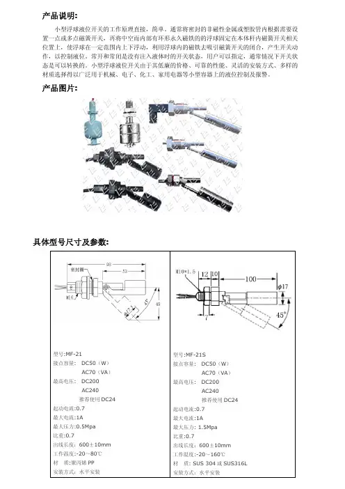
具体型号尺寸及参数:产品说明:小型浮球液位开关的工作原理直接,简单。
通常将密封的非磁性金属或塑胶管内根据需要设置一点或多点磁簧开关,再将中空而内部有环形永久磁铁的的浮球固定在本体杆内磁簧开关相关位置上,使浮球在一定范围内上下浮动,利用浮球内的磁铁去吸引磁簧开关的闭合,产生开关动作,以控制液位。
常开和常闭是没有注入液体时的开关状态,用户可以指定,通常情况下开关状态是可以转换的。
小型浮球液位开关由于其低廉的价格、可靠的性能、灵活的安装方式、多样的材质选择得以广泛用于机械、电子、化工、家用电器等小型容器上的液位控制及报警。
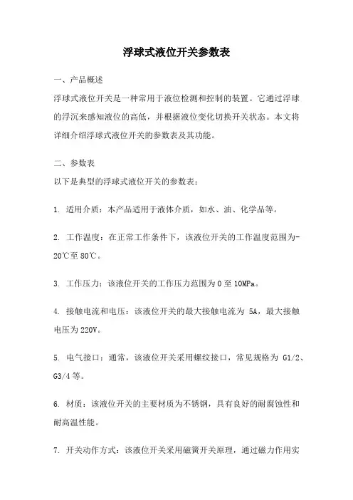
产品图片:型号:MF-21接点容量:DC50(W )AC70(VA )最高电压:DC200AC240推荐使用DC24起动电流:0.7最大电流:1A 最大压力:0.5Mpa 比重:0.7出线长度:600±10mm 工作温度:-20~80℃材质:聚丙烯PP 安装方式:水平安装型号:MF-21S接点容量:DC50(W )AC70(VA )最高电压:DC200AC240推荐使用DC24起动电流:0.7最大电流:1A 最大压力:1.5Mpa 比重:0.7出线长度:600±10mm 工作温度:-20~160℃材质:SUS 304或SUS316L 安装方式:水平安装型号:MF-31接点容量:DC50(W )AC70(VA )最高电压:DC200AC240推荐使用DC24起动电流:0.7最大电流:1A 最大压力:0.5Mpa 比重:0.7出线长度:600±10mm 工作温度:-20~80℃材质:聚丙烯PP 安装方式:水平安装型号:MF-31S接点容量:DC50(W )AC70(VA )最高电压:DC200AC240推荐使用DC24起动电流:0.7最大电流:1A 最大压力:1.5Mpa 比重:0.7出线长度:600±10mm 工作温度:-20~160℃材质:SUS 304或SUS316L 安装方式:水平安装型号:MF-31SH接点容量:DC50(W )AC70(VA )最高电压:DC200AC240推荐使用DC24起动电流:0.7最大电流:1A 最大压力:1.5Mpa 比重:0.7出线方式:德国Hirschmann 接头工作温度:-20~110℃材质:SUS 304或SUS316L 安装方式:水平安装型号:MF-22接点容量:DC50(W )AC70(VA )最高电压:DC200AC240推荐使用DC24起动电流:0.7最大电流:1A 最大压力:1.5Mpa 比重:0.7出线长度:600±10mm 工作温度:-20~160℃材质:SUS 304或SUS316L 安装方式:水平安装型号:MF-2801接点容量:DC50(W )AC70(VA )最高电压:DC200AC240推荐使用DC24起动电流:0.7最大电流:1A 最大压力:1.5Mpa 比重:0.7出线长度:600±10mm 工作温度:-20~130℃材质:SUS 304或SUS316L 安装方式:水平安装型号:MF-2802接点容量:DC50(W )AC70(VA )最高电压:DC200AC240推荐使用DC24起动电流:0.7最大电流:1A 最大压力:1.5Mpa 比重:0.7出线长度:600±10mm 工作温度:-20~130℃材质:SUS 304或SUS316L 安装方式:水平安装型号:MF-3801接点容量:DC50(W )AC70(VA )最高电压:DC200AC240推荐使用DC24起动电流:0.7最大电流:1A 最大压力:2.0Mpa 比重:0.7出线长度:600±10mm 工作温度:-20~130℃材质:SUS 304或SUS316L 安装方式:竖直安装型号:MF-3802接点容量:DC50(W )AC70(VA )最高电压:DC200AC240推荐使用DC24起动电流:0.7最大电流:1A 最大压力:2.0Mpa 比重:0.7出线长度:600±10mm 工作温度:-20~130℃材质:SUS 304或SUS316L 安装方式:水平安装型号:MF-4501接点容量:DC50(W)AC70(VA)最高电压:DC200AC240推荐使用DC24起动电流:0.7最大电流:1A最大压力:3.0Mpa比重:0.7出线长度:600±10mm工作温度:-20~130℃材质:SUS304或SUS316L安装方式:竖直安装型号:MF-4502接点容量:DC50(W)AC70(VA)最高电压:DC200AC240推荐使用DC24起动电流:0.7最大电流:1A最大压力:3.0Mpa比重:0.7出线长度:600±10mm工作温度:-20~130℃材质:SUS304或SUS316L安装方式:水平安装型号:MF-5201接点容量:DC50(W)AC70(VA)最高电压:DC200最高电压:DC200AC240推荐使用DC24起动电流:0.7最大电流:1A最大压力:3.0Mpa比重:0.7出线长度:600±10mm工作温度:-20~130℃材质:SUS304或SUS316L安装方式:竖直安装型号:MF-5202接点容量:DC50(W)AC70(VA)最高电压:DC200最高电压:DC200AC240推荐使用DC24起动电流:0.7最大电流:1A最大压力:3.0Mpa比重:0.7出线长度:600±10mm工作温度:-20~130℃材质:SUS304或SUS316L安装方式:水平安装型号:MF-P19接点容量:DC50(W)AC70(VA)最高电压:DC200AC240推荐使用DC24起动电流:0.7最大电流:1A最大压力:0.5Mpa比重:0.7出线长度:600±10mm工作温度:-20~80℃材质:聚丙烯PP安装方式:竖直安装型号:MF-P26接点容量:DC50(W)AC70(VA)最高电压:DC200AC240推荐使用DC24起动电流:0.7最大电流:1A最大压力:0.5Mpa比重:0.7出线长度:600±10mm 工作温度:-20~80℃材质:聚丙烯PP安装方式:竖直安装。
浮球式液位开关参数表一、产品概述浮球式液位开关是一种常用于液位检测和控制的装置。
它通过浮球的浮沉来感知液位的高低,并根据液位变化切换开关状态。
本文将详细介绍浮球式液位开关的参数表及其功能。
二、参数表以下是典型的浮球式液位开关的参数表:1. 适用介质:本产品适用于液体介质,如水、油、化学品等。
2. 工作温度:在正常工作条件下,该液位开关的工作温度范围为-20℃至80℃。
3. 工作压力:该液位开关的工作压力范围为0至10MPa。
4. 接触电流和电压:该液位开关的最大接触电流为5A,最大接触电压为220V。
5. 电气接口:通常,该液位开关采用螺纹接口,常见规格为G1/2、G3/4等。
6. 材质:该液位开关的主要材质为不锈钢,具有良好的耐腐蚀性和耐高温性能。
7. 开关动作方式:该液位开关采用磁簧开关原理,通过磁力作用实现开关的切换。
8. 浮球材质:通常,该液位开关的浮球采用PP或不锈钢材质,具有良好的浮力和耐腐蚀性。
9. 浮球直径:根据不同的应用需求,该液位开关的浮球直径可选为30mm、50mm、80mm等。
10. 电气接线方式:该液位开关通常采用导线连接方式,其中一端连接电源,另一端连接控制设备。
三、功能说明根据上述参数表,我们可以了解到浮球式液位开关的一些基本特性。
下面将详细说明其主要功能:1. 液位检测:浮球式液位开关可以精确地检测液体的高低,通过浮球的上升和下降来切换开关状态,实现液位的监测和控制。
2. 安全保护:当液位超过或低于设定的阈值时,浮球式液位开关可以发出警报信号,以保护设备和人员的安全。
3. 自动控制:该液位开关可与控制设备配合使用,实现液位的自动控制,如自动注水、排液等。
4. 节能环保:通过对液位的准确控制,该液位开关可以实现节能和环保效果,避免资源的浪费和污染。
5. 多种应用场景:浮球式液位开关广泛应用于水处理、石油化工、食品加工等行业的液位检测和控制领域。
四、使用注意事项在使用浮球式液位开关时,需要注意以下事项:1. 定期清洁:为了保证开关的正常工作,应定期清洁浮球和开关接口,防止污物堵塞影响浮球的浮沉。
L-Series:LIQUID LEVELFLOAT SWITCHSingle-Point, Vertically-Mounted Liquid Level Float SwitchL001, L002, L003, L170, L175, L176, L177, L178, L180, L190 AND L195L001L002L003L170L176L180L190L1952L-SERIES SINGLE-POINT, VERTICALLY-MOUNTED LIQUID LEVEL FLOAT SWITCHThis manual provides information on the L-Series,Single-Point, Vertically-Mounted Liquid Level Float Switch . It is important that all instructionsare read carefully and followed sequentially. Detailed instructions are included in the Complete Installation section of this manual.Conventions Used in this ManualCertain conventions are used in this manual to convey specific types of information. General technical material, support data and safety information are presented in narrative form. The following styles are used for notes, cautions and warnings:NotesNotes contain information that augments or clarifies an operating step. Notes do not normally contain actions and often follow the procedural steps to which they refer.CautionsCautions alert the technician to special conditions that could injure personnel, damage equipment, or reduce a component’s mechanical integrity. Cautions are also used to alert the technician of unsafe practices, the need for special protective equipment, or specific materials. In this manual, a caution indicates a potentially hazardous situation which, if not avoided, may result in minor to moderate injury.Notice of Copyright and LimitationsCopyright © 2015 Solutions With Innovation, LLC; All rights reserved.Solutions With Innovation reserves the right to make changes to the product described in this manual at any time without notice. Solutions With Innovation makes no warranty with respect to the accuracy of the information in this manual.WarrantyAll Solutions With Innovation Mechanical Level and Flow Controls are warranted free of defects in materials and workmanship for one full year from the date of the original factory shipment. If returned within the warranty period; and, upon factory inspection of the control, the cause of the claim is determined to be covered under the warranty; then, Solutions With Innovation will repair or replace the product at no cost to the purchaser (or owner) other than transportation.Solutions With Innovation shall not be liable for misapplication, labor claims, direct or consequential damage, or expenses arising from the installation or use of the equipment. There are no other warranties expressed or implied, except special written warranties covering specific Solutions With Innovation products.Quality AssuranceThe Quality Assurance System in place at Solutions With Innovation guarantees the highest level of quality throughout the company. Solutions With Innovation is committed to providing full customer satisfaction; both in quality products and in quality service.ContactsPhone: 203-729-6434 Mon-Fri, 9 AM - 5 PM EST Fax: 203-729-0541 for General Inquiries Email:***************************READ THIS MANUAL PRIOR TO INSTALLATION3L-SERIES SINGLE-POINT, VERTICALLY-MOUNTED LIQUID LEVEL FLOAT SWITCHL-Series:LIQUID LEVEL FLOAT SWITCHSingle-Point, Vertical MountTABLE OF CONTENTSL001, L 002, L 003, L 170, L 175, L 176, L177, L178, L180, L190 AND L1951.0 Installation1.1 Unpacking.............................................................................41.2 Before You Begin................................................................4 1.2.1 Site Preparation...........................................................4 1.2.2 Equipment and Tools. (4)1.3 Mounting...............................................................................5 1.3.1 Threaded Mounting. (5)1.4 Wiring....................................................................................52.0 Preventative Maintenance2.1 What To Do..........................................................................6 2.1.1 Inspect Entire Unit Periodically.................................6 2.1.2 Inspect Connections Monthly...................................6 2.1.3 Keep Unit Clean. (6)2.2 What To Avoid.....................................................................63.0 Reference Information3.1 Description...........................................................................73.2 Theory of Operation..........................................................73.3 Troubleshooting...................................................................7 3.3.1 External Causes...........................................................7 3.3.2 Unit Causes. (8)3.4 Agency Approvals................................................................83.5 Specifications........................................................................9 3.5.1 Physical Specifications................................................9 3.5.2 Electrical Specifications..............................................9 3.5.3 Dimensional Specifications......................................103.6 Notes...................................................................................103.7 Model Configurator...........................................................113.8 Replacement Parts. (11)1.0 INSTALLATIONThis section provides detailed procedures on properly installing the L-Series Single-Point, Vertically-Mounted Liquid Level Float Switch.CAUTION! IF THE EQUIPMENT IS USED IN A MANNER NOT SPECIFIED BY THE MANUFACTURER, PROTECTION PROVIDED BY THE EQUIPMENT MAY BE IMPAIRED.1.1 UNPACKINGUnpack the instrument, carefully. Make sure that all components have been removed from the packing material. Inspect all components for damage. Report any concealed damage to the carrier within 24 hours of receiving. Compare the contents with the packing slip and report any discrepancies to the factory immediately. Record the sales order number and/or serial number for future reference when ordering parts.Before Proceeding to Installation, Complete the Following:• Inspect all components for damage. Report any damage to the carrier within 24 hours of receiving.• Record the model and serial numbers for future reference when ordering parts.Model NumberSerial Number1.2 BEFORE YOU BEGINCAUTION! DURING THE INSTALLATION OF THE SINGLE-POINT, VERTICALLY-MOUNTED LIQUID LEVEL SWITCH, THE FLOAT AREA MUST BE KEPT FREE OF METALLIC PARTICLES THAT MIGHT BE ATTRACTED TO THE FLOAT’S INTERNAL MAGNET.1.2.1 Site PreparationEnsure that the length and the inside diameter of the mounting is sized correctly to accommodate the L-Series Single-Point, Vertically-Mounted Liquid Level Float Switch.1.2.2 Equipment and ToolsNo special equipment or tools are required to install the L-Series Single-Point, Vertically-Mounted Liquid Level Float Switch.The Following Are Recommended:• Wrenches, thread sealant, gaskets and/or bolting as required for the process connection.4L-SERIES SINGLE-POINT, VERTICALLY-MOUNTED LIQUID LEVEL FLOAT SWITCH5L-SERIES SINGLE-POINT, VERTICALLY-MOUNTED LIQUID LEVEL FLOAT SWITCH1.3 MOUNTINGThe L-Series Single-Point, Vertically-Mounted Liquid Level Float Switch is available in a variety of threaded mountings. These devices can be installed from the bottom or top of the tank. The switches should be mounted in an area clear of turbulence or direct streams.1.3.1 Threaded MountingHow to Install an L-Series Single-Point, Vertically-Mounted Liquid Level Switch:1 Apply either Teflon ® tape or an appropriate thread sealant to the mounting threads to prevent galling.2 Engage the thread by hand to avoid unnecessary damage.3 Using a wrench, rotate the unit clockwise until it is tight within the mounting.1.4 WIRINGCAUTION! OBSERVE ALL APPLICABLE ELECTRICAL CODES AND PROPER WIRING PROCEDURES.Contact Protection:In order to maintain the life and reliability of the internal reed switch, it is essential to provide protection when switching inductive loads. When the current breaks, the energy stored in the load generates a high frequency voltage across the switch contacts. If the voltage is large enough, it can initiate arcing and cause the contacts to weld together. Damage can ultimately be prevented by suppressing the voltage. Through the use of a diode for DC circuits and a resistor-capacitor network for AC circuits, contact protection willensure reliable performance from the reed switch.TOP MOUNT BOTTOM MOUNTANGLED MOUNT6L-SERIES SINGLE-POINT, VERTICALLY-MOUNTED LIQUID LEVEL FLOAT SWITCH2.0 PREVENTATIVE MAINTENANCEPeriodic inspections are necessary to maintain the proper functionality of the L-Series Single-Point, Vertically-Mounted Liquid Level Switch. The switch is a safety device that protects the equipment it serves. A systematic program of preventative maintenance should be implemented at the time of installation. If the following instructions are completed routinely, the switch will provide continuous, reliable protection.2.1 MAINTENANCE PROCEDURES 2.1.1 Inspect Unit PeriodicallyVerify that there are no cracks or chipped surfaces on the float or stem. Should the unit become damaged, obtain a replacement immediately.2.1.2 Inspect Connections MonthlyL-Series Single-Point, Vertically-Mounted Liquid Level Switches may be vulnerable to excessive heat and moisture. Under these conditions, the electrical wire insulation can periodically break or peel away. As a result, the bare wires may become exposed to the elements and cause damages.• Inspect all wiring, carefully and replace any wires exhibiting signs of brittle insulation.• Inspect all electrical connections to ensure tightness.• Repair or replace any wiring, if necessary.2.1.3 Keep Unit CleanPeriodic cleanings of the float, stem and magnet assembly will ensure the continual, uninterrupted movement of the mechanism. Always keep the open area between the enclosures clean and free of any potential interferences. Objects and debris may cause systematic interruptions and a loss in equipment functionality.2.2 WHAT TO AVOIDNEVER LEAVE THE SWITCH WIRING EXPOSED TO THE ELEMENTS.NEVER PLACE A JUMPER WIRE ACROSS THE TERMINALS TO “CUT-OUT” THE CONTROL. If a jumper is necessaryfor testing purposes, ensure that it is removed prior to placing the control into service.NEVER USE IN SYSTEMS CONTAINING IRON PARTICLES. The magnet within the float assembly can attract the particlesand become jammed.3.0 REFERENCE INFORMATIONThis section illustrates an overview of the L-Series Single-Point, Vertically-Mounted Liquid Level Switch, as well as information on troubleshooting common problems, agency approval listings, and detailed physical, functional and performance specifications.3.1 DESCRIPTIONThe L-Series Single-Point, Vertically-Mounted Liquid Level Switchis a float-actuated device designed to be vertically mounted within atank or process vessel through threaded connections. The low-costswitch is ideal for OEM applications where a single-point high or lowlevel alarm is desired.3.2 THEORY OF OPERATIONThe switching action is achieved through the use of an internalmagnet within the float assembly and its interaction with the switchmechanism. As the liquid level fluctuates inside the tank, the floatfollows. Its magnetic field actuates the switch inside the stem andcloses an electrical circuit.FLOAT SWITCH DIAGRAM3.3 TROUBLESHOOTINGThe L-Series Single-Point, Vertically-Mounted Liquid Level Switch is designed and engineered for trouble-free operation over a wide range of operating conditions. Common problems are discussed in terms of their symptoms and recommended corrective actions.3.3.1 External CausesAn initial indication of improper operation is the failure of the controlled equipment to function (pumps will not start or stop, signal lamps fail to light, etc). If these symptoms occur, whether at the time of installation or during routine service thereafter, check for potential external causes first:• Blown Fuses• Tripped Reset Button(s)• Open Power Switch• Faulty Equipment Controlled By the Level Switch• Defective Wiring to the Level SwitchL-SERIES SINGLE-POINT, VERTICALLY-MOUNTED LIQUID LEVEL FLOAT SWITCH78L-SERIES SINGLE-POINT, VERTICALLY-MOUNTED LIQUID LEVEL FLOAT SWITCH3.3.2 Unit CausesIf a thorough inspection of any external causes fails to locate the problem, proceed to an inspection of the unit, itself.DISCONNECT POWER TO THE LEVEL SWITCH BEFORE PROCEEDING.If you are still in doubt about the condition or performance of your control, consult the factory for further instructions.3.4 AGENCY APPROVALS3.5 SPECIFICATIONS3.5.1 Physical Specifications3.5.2 Electrical SpecificationsL-SERIES SINGLE-POINT, VERTICALLY-MOUNTED LIQUID LEVEL FLOAT SWITCH910L-SERIES SINGLE-POINT, VERTICALLY-MOUNTED LIQUID LEVEL FLOAT SWITCH3.5.3 Dimensional Specifications3.6 NOTESHEX11L-SERIES SINGLE-POINT, VERTICALLY-MOUNTED LIQUID LEVEL FLOAT SWITCH3.7 MODEL CONFIGURATOR3.8 REPLACEMENT PARTSWhen Ordering, Please Specify:• Model & Serial Numbers• Name & Part Number of Replacement Part or AssemblyAll replacement parts are for standard models only. Contact the manufacturer for ordering assistance on all specially modified models (model numbers followed by a “C”; i.e. L003C, L177C, etc.)STEM & SWITCH SUB-ASSEMBLYFLOATCLIPService PolicyOwners of Solutions With Innovation products may request a return of the product, or any part of the product for complete rebuilding or replacement. Units will be rebuilt or replaced promptly. Products returned under the SWI Service Policy must be returned by prepaid transportation. Solutions With Innovation will repair or replace the product at no cost to the purchaser (or owner) other than transportation if:1 Returned within the warranty period; and2 Factory Inspection finds the cause of the claim to be covered under the warranty.If the problem is due to circumstances beyond Solutions With Innovation’s liability, or is NOT covered by the warranty, there will be charges for labor in addition to the parts required to rebuild or replace the equipment.In rare cases, it may be expedient to ship replacement parts; or in extreme cases, an entire product before the damaged product is returned. If a quick replacement service is necessary, notify the manufacturer of the damaged product’s model and serial number. In such cases, credit for the returned materials will be determined on the applicability of the warranty.No claims for misapplication, labor, direct or consequential damage will be allowed.Return Material ProcedureIn order to efficiently process any returned materials, it is essential that a Return Material Authorization (RMA) number be obtained from the manufacturer prior to an item’s return. RMA’s can be issued through local representatives, or by contacting the factory directly. Please supply the following information: 1 The Company’s Name 2 Description of the Material 3 Product Serial Number 4 Reason for Return 5 Product’s ApplicationUsed units must be properly cleaned in accordance with OSHA standards before it is returned to the manufacturer. A Material Safety Data Sheet (MSDS) must accompany units or materials that were used in any type of media. All return shipments to the factory must be by done via prepaid transportation. All product replacements will be shipped F.O.B. manufacturer.BULLETIN: IS-9110.2EFFECTIVE: 1/15。
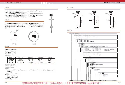
产品外形图HR-FZ系列浮球式液位变送器HR-FZ系列浮球式液位变送器产品选型HR-FZ-1/2 HR-FZ-3 HR-FZ-4产品介绍HR-FZ系列浮球式液位变送器,用于将容器内的介质液位变送为4~20mA二线制标准信号输出。
另外,变送器还可以提供现场指示。
该系列产品有普通型、防腐型、防爆型等,防腐型对强腐蚀介质有极好的抗腐蚀性能,防爆型可用于易燃易爆场合。
该产品广泛应用于化工、电力、造纸、食品、环保和城建等行业,例如污水处理、地埋油罐及高层水箱的液位测量。
工作原理技术参数变送器由液位传感器和信号转换器两部分组成,传感器导杆外的浮球随液位变化沿检测管上下移动,浮球内的永久磁钢控制导杆内的干簧管吸合或断开,从而使传感器内电阻值呈线性变化,再由信号转换器将这个阻值的变化转换成4~20mA直流信号输出。
24V DC∑R inl=1R xR n0%100% 工作原理图 接线图测量范围:300~6000mm 精确度:±10mm电源:24VDC (15~35V)输出:4~20mA 二线制仪表工况条件如下:环境温度:-40~80℃介质密度:0.4~2.0g/cm 3介质粘度:≤0.8Pa·S 过程连接:法兰安装:HG20592~20635-97,其他法兰标准(如GB、JB/T、HGJ、ANSI、DIN等)请在订货时注明 支架安装电气接口:M20×1.5 内螺纹防爆等级:隔爆型:ExdIIBT1~T6; 本安型:ExiaIICT1~T6 防护等级:IP65系列号HR-FZ-1/2HR-FZ-3HR-FZ-4接液材质不锈钢不锈钢衬PP 不锈钢衬PTFE工作温度℃-40~120-40~80-40~120工作压力MPa -0.1~2.50~1.0-0.1~1.6过程法兰DN50以上DN80以上DN80以上产品选型工作温度:-30~120℃环境温度:-40~70℃工作压力:-0.1~2.5MPa 介质密度:≥0.5g/cm 3输出信号:常开、常闭或常开常闭干簧触点触点容量:220VAC 1A;24VDC 0.5A 开关寿命:5×10⁴次电气接口:M20×1.5 内螺纹防爆等级:隔爆型:ExdIIBT1~T6 本安型:ExiaIICT1~T6 防护等级:IP65过程连接:HG20592~20635-97 DN50以上,其他法兰标准(如GB、JB/T、HGJ、ANSI、DIN等)请在订货时注明接液材质:不锈钢;PP;PTFE 接线盒材质:铝合金注:选型表格中的常开\常闭是指干簧管不受磁钢作用下的自然状态HR-YKA系列浮球式液位控制器适用于石油、化工、纺织印染、环保、民用建筑等各种敞口或密闭容器内各种介质的单点或多点液位的控制和报警。
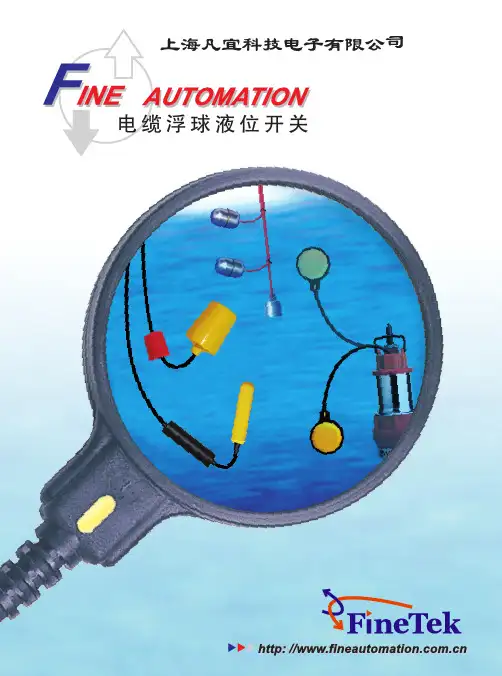
浮球液位开关型号及原理浮球液位开关使用磁力运作,无机械连接件使其运作简单可靠,成本更为低廉,当浮球液位开关被测介质浮动浮子时,浮子带动主体随之移动,同时浮子另一端的磁体将控制开关动作杆上的磁体,操作简单快捷,使其在造船、印刷、造纸、发电机设备、食品工业、石油化工、电工、水处理、染料工业、油压机械等领域得到广泛应用。
下面就是装修界小编对于浮球液位开关型号及原理具体介绍,希望对大家在使用上有所借鉴作用。
浮球液位开关-优势浮球液位开关在技术上存在其特有的优势,不含有导致故障发生的波纹管、密封、弹簧等部件,采用直浮子驱动开关内部磁铁,浮球开关的简捷杠杆原理使开关瞬间动作。
浮子悬臂角限位设计,防止了浮子垂直。
浮球液位开关结构设计简单、使用方便、安全可靠,比一般机械开关效果更好、使用寿命更加长久,被广泛适用于各行各领域之中。
浮球液位开关-原理利用浮球液位开关的磁性浮子随着液位升降,使传感器检测管内设定位置的干簧管芯片动作,发出接点开关的转换信号。
一般会在密闭的非导磁性管内安装一个或多个干簧管,将此管穿过一个或多个中空并且内部有环形磁铁的浮球,液体的上升或下降会带动浮球一起上下移动,使该非导磁性管内的干簧管产生吸合或断开的动作,从而实现输出一个开关信号的作用。
浮球液位开关-型号浮球液位开关的型号大部分都是依据厂家而定的,没有一个相同标准,市面上比较常见的型号有:zc_pp251、zc_pp311、zc_pp441、zc_pp521、zc_pp731、zc_pp851侧装有zc_pl_1、zc_pl_2等,浮球液位开关在销售上大多都是根据客户需要进行定制的,以上型号只是一个参考,要根据实际情况进行选择。
浮球液位开关-特点浮球液位开关可以分为固定磁浮球液位开关和可调控浮球液位开关,在选择时要考虑固定和可调磁滞现象、安装位置、液体密度、连接效果等。
浮球液位开关适用范围广泛,安装形式多样可根据不同需要进行选择,无源器件、抗干扰能力强、性能稳定可靠、安装方便、结构简单、维护费用低等特点,受到广大消费者喜爱和支持。

浮球液位开关工作原理
浮球液位开关是一种常用的液位测量仪器,其工作原理是通过浮球的上下浮动来检测液体的液位高低。
浮球液位开关包含一个密封的浮球和一个与其相连的开关组件。
具体而言,当液体的液位升高时,浮球会随之上浮,直到达到预定的高位位置。
在浮球上方的开关组件会受到浮球的上浮而受压,从而使开关闭合。
这时,浮球液位开关会输出一个信号,表示液位已经达到高位。
相反地,当液体的液位下降时,浮球会随之下沉,直到达到预定的低位位置。
在浮球下方的开关组件会受到浮球的下沉而释放,从而使开关打开。
这时,浮球液位开关会停止输出信号,表示液位已经低于设定的低位。
浮球液位开关常用于液体容器或储罐中,用于控制液位高低。
当液位达到设定的高位位置时,浮球液位开关会触发相应的控制系统,例如关闭进液阀门,以避免液体溢出。
当液位降至设定的低位位置时,浮球液位开关会触发相应的操作,例如打开排液阀门,以补充液位。
总的来说,浮球液位开关利用浮球上下浮动的原理,通过开关组件的闭合和断开来检测液体的液位高低,从而实现液位的控制和监测功能。

浮球液位开关的用途浮球液位开关是一种常用的液位检测装置,广泛应用于各行各业的液位控制系统中。
它通过浮球的浮沉来感知液位的变化,并将信号传递给控制系统,以便控制液位的稳定。
浮球液位开关的用途非常广泛。
下面我们分别从工业、农业和家庭三个方面来介绍它的具体用途。
在工业领域,浮球液位开关常用于化工、石油、食品加工等行业的液位控制系统中。
例如,在化工行业中,浮球液位开关可以用于监测化学反应釜的液位,及时控制液位的上下限,避免溢出和干涸。
在石油行业中,浮球液位开关可用于油罐的液位监测,确保油罐储存的油量充足,并及时报警处理异常情况。
在食品加工行业中,浮球液位开关可用于监测食品罐的液位,确保生产过程中液位的稳定,避免浪费和污染。
在农业领域,浮球液位开关常用于农田灌溉系统中。
例如,在自动灌溉系统中,浮球液位开关可以用于监测水箱或水井的水位,当水位过低时,及时启动水泵进行灌溉,当水位过高时,及时停止水泵以避免溢出。
这样不仅可以提高农田的灌溉效率,还可以节约水资源,减轻劳动强度。
在家庭生活中,浮球液位开关也有很多实用的用途。
例如,在水箱中安装浮球液位开关,可以监测水位,当水位过低时,及时启动水泵进行补水,保证家庭用水的正常供应;当水箱水满时,浮球液位开关会自动停止水泵,避免浪费。
此外,浮球液位开关还可以用于监测浴缸、水槽等的水位,当水位过高时,及时停止水流,避免溢出。
除了以上提到的领域,浮球液位开关还有许多其他的用途。
例如,在污水处理系统中,浮球液位开关可以用于监测沉淀池的液位,及时控制泵的工作状态,确保污水处理的效果。
在火灾报警系统中,浮球液位开关可以用于监测消防水箱的水位,当水位过低时,及时报警,保证消防水源的充足。
在汽车燃油系统中,浮球液位开关可以用于监测油箱的燃油量,及时提醒驾驶员加油,确保行驶的安全。
浮球液位开关作为一种常用的液位检测装置,在工业、农业和家庭等领域都有着广泛的用途。
它通过浮球的浮沉来感知液位变化,并将信号传递给控制系统,以便控制液位的稳定。
日常维护1、定期清除浮球管及浮球上的污垢(周期视水质而定)。
2、检查环扣上的螺钉是否有松动。
开箱及检查1、包装应完好无损。
2、开箱时若发现本产品有损坏或部件脱落松动,请及时通知本公司。
3、装箱内容:a)产品1台b)使用说明书1份c)产品合格证使用重点注意事项1、浮球开关所接电路电压必须小于磁簧开关最高电压,电流必须小于其最大工作电流:对于 10W/125V AC 交流电压<125V AC I<1A50W/240V AC/200V DC 交流电压<240V AC I<1A直流电压<200V DC I<1A2、浮球开关连接在电路中,其起动电流必须小于1A。
3、浮球开关连接在电路中,其消耗功率最大为10W、20W、40W、50W,若电路的功率大于其额定功率,可能会导致磁簧烧毁。
4、浮球开关必须经过继电器然后再控制其它负载,也可以给PLC直接采集信号。
5、浮球开关应避开大的变频器及大功率的电动机和电容器。
6、浮球开关所控制位置出厂前已设定好,请不要随意移动环扣位置,环扣移动将可能导致浮球开关信号输出错误或无信号输出。
小型浮球液位开关使用说明书地址:陕西省宝鸡市英达路18号电话:************传真:************邮编:721006网址:制订日期:2019年01月23日 V2.0版基本参数1、温度:-10℃~120℃(SUS 、Max200℃订制);-20℃~80℃(PP);-20℃~120℃(PVDF、Nylon等)2、耐压:0.3MPa (PVDF);0.4MPa(PP);6.4 MPa(Max)3、接点容量:50W/250V AC或200V DC;10W/110V AC;40W/250V AC4、最大切换电流:0.5A5、最大工作电流:1A(50W或40W);0.5A(10W)6、最大开关电压:125V AC;240V AC或200V DC7、动作次数:106次以上注:温度超过80℃及压力超过0.5MPa时需订做。
小型浮球液位开关产品原理:通常将密封的非磁性金属或塑胶管内根据需要设置一点磁簧开关,再将中空而内部有环形磁铁的浮球固定在杆径内磁簧开关相关位置上,浮球比重小于液体密度,液体使浮球在一定范围内上下浮动,利用浮球内的磁铁去吸引磁簧开关的闭合,产生开关动作,以控制液位。
常开和常闭是没有注入液体时的状态。
产品特点:磁簧开关触点材料为铑(表层覆盖氧化铑),接点寿命可达200万次。
磁簧开关的特殊处理可使其在200℃高温下正常使用。
浮球开关整体性能可靠,多种材质和规格可供选择。
型号:LS-S1A1,LS-S2A1,LS-S1A38,LS-S1A38,LS-S1A2,LS-S2A2,LS-S1A3,LS-S2A3,LS-SYZ-2,LS-SYZ-2H,LS-YZ-1,LS-YZ-2,LSP-001, LSP-002型号:LS-S1A1o技术参数o接点容量:70Wo最高工作电压:240VAC/200VDCo最大开关电流:0.7Ao最大压力:10Kg/cm 2o浮球比重:0.8g/cm3o工作温度:-20~120℃o浮球尺寸:φ28×28×φ9.5o材质:SUS304 or SUS316Lo过程连接:1/8″PF(可定制)型号:LS-S2A1o 技术参数o 接点容量:70W o 最高工作电压:240VAC/200VDCo 最大开关电流:0.7A o 最大压力:10Kg/cm 2 o 浮球比重:0.8g/cm3 o 工作温度:-20~120℃ o 浮球尺寸:φ28×28×φ9.5 o 材质:SUS304 or SUS316L o 过程连接:1/8″PF (可定制)型号:LS-S1A38o 技术参数o 接点容量:70W o 最高工作电压:240VAC/200VDCo 最大开关电流:0.7A o 最大压力:10Kg/cm 2 o 浮球比重:0.7g/cm3 o 工作温度:-20~120℃ o 浮球尺寸:φ38×26×φ9.5 o 材质:SUS304 or SU 过程连接:1S316L o /8o 技术参数o 接点容量:70W o 最高工作电压:240VAC/200VDCo 最大开关电流:0.7A o 最大压力:10Kg/cm 2 o 浮球比重:0.7g/cm3 o 工作温度:-20~120℃ o 浮球尺寸:φ38×26×φ9.5 o 材质:SUS304 or SU 过程连接:1/S316L o 8″PF (可定制)型号:LS-S1A2o 技术参数VAC/200VDCo 接点容量:70Wo 最高工作电压:240o 最大开关电流:0.7A o 最大压力:15Kg/cm 2 o 浮球比重:0.65g/cm3 o 工作温度:-20~120℃ o 浮球尺寸:φ45×55×φ15 o 材质:SUS304 or SUS316L o 过程连接:3/8″PF (可定制)o技术参数o接点容量:70Wo最高工作电压:240VAC/200VDCo最大开关电流:0.7Ao最大压力:15Kg/cm 2o浮球比重:0.65g/cm3o工作温度:-20~120℃o浮球尺寸:φ45×55×φ15 o材质:SUS304 orSUS316Lo过程连接:3/8″PF可定制型号:LS-S1A3o技术参数o接点容量:70Wo最高工作电压:240VAC/200VDCo最大开关电流:0.7Ao最大压力:30Kg/cm 2o浮球比重:0.55g/cm3o工作温度:-20~120℃o浮球尺寸:φ52×52×φ15 o材质:SUS304 orSUS316Lo过程连接:3/8″PF(可定制)型号:LS-S2A3o技术参数o接点容量:70Wo最高工作电压:240VAC/200VDCo最大开关电流:0.7Ao最大压力:30Kg/cm 2o浮球比重:0.55g/cm3o工作温度:-20~120℃o浮球尺寸:φ52×52×φ15o材质:SUS304 or SUS316Lo过程连接:3/8″ PF(可定制)型号:LS-SYZ-2o技术参数o接点容量:70Wo最高工作电压:240VAC/200VDCo最大开关电流:0.7Ao最大压力:10Kg/cm 2o浮球比重:0.7g/cm3o工作温度:-20~120℃o材质:SUS304 or SUS316Lo过程连接:1/2″ PF or PT(可定制)型号:LS-SYZ-2Ho技术参数o接点容量:70Wo最高工作电压:240VAC/200VDC o最大开关电流:0.7Ao最大压力:10Kg/cm 2o浮球比重:0.7g/cm3o工作温度:-20~120℃o材质:SUS304 or SUS316Lo过程连接:1/2″ PF or PT(可定制)型号:LS-YZ-1o技术参数o接点容量:70Wo最高工作电压:240VAC/200VDC o最大开关电流:0.7Ao最大压力:4Kg/cm 2o浮球比重:0.8g/cm3o工作温度:-20~80℃o材质:PP or FRPPo过程连接:1/2″PT,M20*1.5)型号:LS-YZ-2o技术参数o接点容量:70Wo最高工作电压:240VAC/200VDCo最大开关电流:0.7Ao最大压力:4Kg/cm 2o浮球比重:0.8g/cm3o工作温度:-20~80℃o材质:PP or FRPPo过程连接:1/2″PT,M20*1.5型号:LSP-001型号:LSP-002公司名称 :佛山市斯凯韦尔电子有限公司公司地址 :佛山市禅城区人民西路13号6栋4层联系人 :刘锋139****5588电话号码 :86-757-82323721 82208956传真号码 :86-757-82514068网址 :E-mail :***************连杆浮球液位开关产品原理:连杆浮球液位开关与小型浮球液位开关原理基本相同,通常将密封的非磁性金属或塑胶管内根据需要设置一点或多点磁簧开关,再将中空而内部有环形磁铁的的浮球固定在杆径内磁簧开关相关位置上,使浮球在一定范围内上下浮动,利用浮球内的磁铁去吸引磁簧开关的闭合,产生开关动作,以控制液位。
UQZMAGNETIC FLOAT LEVEL TRANSMITTER UQZ型磁浮球液位变送器使用说明书UQZ-DT-JS-1004-2018(A)前言感谢您选择丹东通博电器(集团)有限公司的产品。
本使用说明书给您提供有关安装、连接和调试以及针对维护、故障排除和贮存方面的重要信息。
请在安装调试前仔细阅读并将它作为产品的组成部分保存在仪表的近旁,供随时翻阅。
并可通过输入版本号下载本说明书。
如未遵照本说明书进行操作,则本仪表所提供的防护可能会被破坏。
商标、版权和限制说明通博、通博电器、通博泵业、DDTOP、均为公司的注册商标。
本仪表的性能规格自发布之日起生效,如有更改,恕不另行通知。
丹东通博电器(集团)有限公司有权在任何时候对本说明书所述的产品进行修改,恕不另行通知。
质保丹东通博电器(集团)有限公司保证所有刮板流量计自出厂之日起,一年之内无材料和制造工艺方面的缺陷。
在质保期内,如产品出现质量问题而返回,提出的索赔要求经制造厂检验后确定属于质保范围内,则丹东通博电器(集团)有限公司负责免费为买方(或业主)维修或更换。
丹东通博电器(集团)有限公司对因设备使用不当,劳动力索赔、直接或后续损伤以及安装和使用设备所引起的费用概不负责。
除了关于丹东通博电器(集团)有限公司某些产品的特殊书面保修证明,丹东通博电器(集团)有限公司不提供任何明示或暗示的质量保证。
质量丹东通博电器(集团)有限公司通过了ISO9001质量体系认证,产品生产的全过程均严格依照质量体系的规定范围执行,对产品和服务质量提供最强有力的保证。
目录1安全提示 (4)1.1爆炸可能会导致死亡或严重伤害。
(4)1.2过程泄漏可能导致严重伤害或死亡。
(4)1.3不遵守安全安装准则可能导致死亡或严重受伤。
(4)2产品说明 (4)2.1 产品主要结构 (4)2.2工作原理 (5)2.3包装 (5)2.4吊装运输时 (5)2.5仓储 (5)3技术特性 (5)3.1主要性能 (5)3.2 主要参数 (5)4外形尺寸示意图 (6)5开箱及检查 (6)5.1开箱验货注意事项 (6)5.2检查内容 (7)6安装 (7)6.1安装工具 (7)6.2安装技术要求 (7)6.3 安装操作过程 (7)7 调试 (8)7.1变送器调试 (8)8 注意事项 (12)9 故障分析与排除 (12)10 拆卸 (12)10.1警告 (12)10.2废物清除 (12)11 产品认证 (12)1安全提示出于安全的原因,明确禁止擅自改装或改变产品,维修或替换只允许使用由制造商指定的配件。
Float switchFor the process industry, vertical installation Models FLS-S, FLS-M, FLS-P , FLS-HData sheets showing similar products:Fig. left: Stainless steel version, mounting thread, model FLS-SFig. right: Plastic version, flange connection,model FLS-P■Level measurement for almost all liquid media■Pump and level control and monitoring of distinct fillinglevels■Chemical, petrochemical industry, natural gas, offshore, shipbuilding, machine building, power generating equipment, power plants■Process water and drinking water treatment, food and beverage industrySpecial features■Large range of application due to the simple, proven functional principle■For harsh operating conditions, long service life■Operating limits:- Operating temperature:T = -50 ... +350 °C - Operating pressure:P = Vacuum up to 40 bar - Limit density:ρ ≥ 300 kg/m 3■Wide variety of different electrical connections, process connections and materials■Explosion-protected versionsDescriptionA float with a permanent magnet moves reliably along with the liquid level on a guide tube. Within the guide tube is fitted a reed contact (inert gas contact), which is energised, through the non-magnetic walls of the float and guide tube, by the approach of the float magnet. By using a magnet and reed contact the switching operation is non-contact, free from wear and needs no power supply. The contacts are potential-free. Float switches are also available with multiple switch points.The switching functions always refer to a rising liquid level: Normally open, normally closed or change-over contact.Through the use of a float for a max. of 2 switch points abistable switch behaviour can be achieved, meaning that the switching status also remains available, when the filling level continues to rise above or drop below the switch point.The float switch is simple to mount and maintenance-free, so the costs of mounting, commissioning and operation are low.for further approvalssee page 3WIKA data sheet LM 30.01Page 1 of 19WIKA data sheet LM 30.01 ∙ 05/2021Model overviewFurther special features■Process connection, guide tube and float from stainless steel 1.4571, plastic or Buna■Universal signal processing:Connection direct to a PLC is possible, NAMURconnection, signal amplification / contact protection relays■Works independently of foaming, conductivity, dielectricity, pressure, vacuum, temperature, vapours, condensation, bubble formation, boiling effects and vibrations■Multiple functionality in a single instrument - up to 8 potential-free contacts■Exact repeatability of the switch points■Float switches qualify as simple apparatus in accordance with EN 60079-11 section 5.7 and can be installed in “zone 1” hazardous areas without certification, so long as the equipment is operated in a certified intrinsically safe circuit with a minimum explosion protection of Ex ib.Options■Customer-specific solutions■Special versions for interface layer detection∆-ρ ≥ 100 kg/m 3■Process connection, guide tube and float from stainless steel 1.4435, 1.4539, titanium, Hastelloy (others on request)T emperature range (process)■Models FLS-SE, FLS-SF, FLS-HE-30 ... +180 °C■Models FLS-SA, FLS-SB-50 ... +350 °C■Model FLS-SxI (60)-50 ... +180 °C■Models FLS-SxD (AL-ADF)-10 ... +120 °C■Model FLS-M-10 ... +100 °C■Model FLS-P-10 ... +100 °C■Models FLS-HA, FLS-HA3-40 ... +200 °C■Model FLS-F-30 ... +180 °CIngress protection (IP code) per EN 60529:1991 + A1:2000 + A2:2013■With aluminium or stainless steel connection housing IP66/IP68■With plastic connection housing or connector IP65All ingress protections depend on the cable gland, sealing (e.g. O-ring) and cable used. Approvals■Model FLS-S■Models FLS-H, FLS-P, FLS-M, FLS-FApplication examplesIntrinsically safe relaye.g. KFD2-SR2-Ex2.We.g. KFD2-ER-1.6 e.g. KFD2-ER-1.6Standard version with connection housing or connector, models FLS-SA, FLS-SB Process connection, guide tube and float from stainless steel 1.4571 (316Ti)Standard version with cable connection, models FLS-SE, FLS-SFProcess connection, guide tube and float from stainless steel 1.4571 (316Ti)Intrinsically safe (Ex i), model FLS-SBI (60)II 1/2G Ex ia IIC T6 ... T1 Ga/Gb or II 2D Ex ib IIIC T80°C ... T230°C DbProcess connection, guide tube and float from stainless steel 1.4571 (316Ti)Flameproof enclosure (Ex d), models FLS-SAD, FLS-SBD (AL-ADF)II 2G Ex d IIC T6 Gb or II 2D Ex tb IIIC T80 °C DbProcess connection, guide tube and float from stainless steel 1.45711) FLS-MF (connection cable), FLS-MA (connection housing or connector) versions on requestMiniature design, models FLS-ME, FLS-MBProcess connection, guide tube 8 mm and float from stainless steel 1.4571 (316Ti)Plastic version, models FLS-PA, FLS-PF Process connection, guide tube and float from PVC, PP or PVDFPharmaceutical version, models FLS-HA, FLS-HEProcess connection, guide tube and float from stainless steelSterile version (3-A), model FLS-HA3Process connection, guide tube and float from stainless steelOptional versionsFood version for float switch, model FLS-F Process connection, guide tube and float from stainless steelNote: The optimum float will be selected after a feasibility test carried out by WIKA.Note: The optimum float will be selected after a feasibility test carried out by WIKA.Note: The optimum float will be selected after a feasibility test carried out by WIKA.Ordering informationT o order the described product the order number (if available) is sufficient.Alternatively:Model / Version / Electrical connection / Process connection / Guide tube diameter / Guide tube length L / Information about contact (switching function, number of switch points, switch position) / Process specifications (operating temperature and pressure, limit density) / Options© 01/2010 WIKA Alexander Wiegand SE & Co. KG, all rights reserved.The specifications given in this document represent the state of engineering at the time of publishing.We reserve the right to make modifications to the specifications and materials.Contact protection measuresThe reed contacts should be protected against any voltage or current spikes that might occur.Depending on the different load types different protectivecircuits are used.WIKA Alexander Wiegand SE & Co. KG Alexander-Wiegand-Straße 3063911 Klingenberg/Germany 05/2021 E NPage 19 of 19WIKA data sheet LM 30.01 ∙ 05/2021Model KFD2-ER-1.6RC element。
浮球液位开关原理
浮球液位开关是一种常用的液位检测装置,它可以根据液体的液位高低来控制开关的状态。
浮球液位开关主要由浮球、导向杆、固定杆、开关装置和电路组成。
浮球是浮球液位开关的核心部件,通常是一个中空的球形物体,它的密度小于液体,可以浮在液体表面。
导向杆和固定杆是用来固定浮球的,导向杆通常与固定杆相连,确保浮球在液体中垂直浮动。
当液位低于设定的阈值时,浮球下沉,导致导向杆也下沉;而当液位高于阈值时,浮球上浮,导致导向杆也上浮。
导向杆的上下运动会触动开关装置,在液位低于阈值时,开关断开;而在液位高于阈值时,开关闭合。
开关装置在液位低于阈值时断开电路,使得相应的设备或系统停止工作;而在液位高于阈值时闭合电路,使得相应的设备或系统开始工作。
浮球液位开关的原理是基于浮力和重力的平衡关系。
当液位低于阈值时,浮球向下受重力作用下沉,导致开关断开;而当液位高于阈值时,浮球向上受浮力作用上浮,导致开关闭合。
通过控制开关的状态,可以实现对液位的检测和控制。