SP、SPR型液下渣浆泵说明书
- 格式:doc
- 大小:1.48 MB
- 文档页数:28
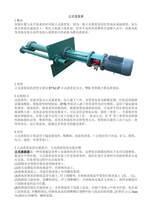
立式渣浆泵1概念泵轴位置与水平面垂直时叫做立式渣浆泵。
因为一般立式渣浆泵用在浆池坑来抽渣浆,泵头部分要放在液面以下,所以又称液下渣浆泵,但并不是所有的整体全部潜入水中,如果电机等其他非泵头部件也投入到渣浆中的泵称为潜水渣浆泵。
2类型立式渣浆泵的类型主要以EVM,SP立式渣浆泵为主,WO类型属于潜水渣浆泵。
3结构特点过流部件:该系列泵为立式渣浆泵,浸入液下工作。
该型泵泵体为耐磨金属,叶轮选用耐磨金属或橡胶、聚胺脂等材料制造。
EVR型泵浸入液下的零部件均衬有橡胶,适用于输送腐蚀性渣浆。
轴承组件:轴承采用油脂润滑。
根据渣浆池液面的高低,可选择不同长度的泵传动轴或吸入管。
在池水深度有较高要求下,可以采用定制加长轴。
轴封(密封):不需要任何轴封和轴封水,在吸入量不足的工况下也能正常工作。
传动方式:有V型三角带传动和弹性联轴器传动等。
整体性能:采用多种速度和多种变型方式,使得泵在最佳工况下运行,使用寿命长,运行效益高,能满足多类恶劣的输送条件。
4应用立式渣浆泵主要适用于输送腐蚀性、粗颗粒、高浓度渣浆。
广泛地应用于冶金、矿山、煤炭、电力、建材、环保等部门。
5立式渣浆泵的安装要点,立式渣浆泵的安装步骤立式渣浆泵是一种用来输送各种工业液体的真空泵,这种泵在耐腐蚀情况下也可以耐磨损,能适应不用环境,立式渣浆泵的安装工作是很重要的,我们在进行安装时应该按照要求去进行安装,以免使用过程中出出现异常。
(1)将轴承分别装在轴承盒和轴承座上。
(2)将毛毡圈装在轴承端盖甲、丙和轴承盒上。
(3)将轴承端盖乙、丙装在轴承座上并用螺栓紧固。
(4)将装好轴承的轴承盒穿在轴上,拧上圆螺母,并将轴承端盖甲紧固在轴承盒上(美,,宝)。
(5)将轴装入轴承座,用螺栓固定,拧上调整螺钉,并将轴承安装在支承座上,将挡水圈套在下部轴承处的适当位置。
(6)将联接管固定在轴承座上,并在联接管下部装上泵盖,在轴下部装上叶轮并拧紧,依次装上泵体前盖,并螺栓固定,用轴承盒处的调整螺钉调整叶轮与前盖间的间隙,(控制在1--1.5mm 内)调好后用螺母,螺栓紧固。
目录一、概述 (2)二、特点 (2)三、型号和表示方法 (3)四、工作原理 (3)五、结构说明 (3)六、装配和拆卸 (4)七、设备安装 (5)八、运转 (6)九、维护保养 (7)十、故障分析 (9)附录1(耐磨材料选择表)附录2(密封型式选择表)附录3(泵传动方式选择)一、概述1、本系列渣浆泵系高效节能、单级、单吸、悬臂式离心泵,用来输送含有固体颗粒的磨蚀性或腐蚀性浆体。
广泛用电力、矿山、冶金、煤炭、建材、化工、食品、水利及污水处理等行业。
其固液混合体的最大重量浓度:灰浆为45%,矿浆为60%。
2、本系列泵有50多个基本型号,通过变速可获得300多种性能供用户选择。
3、过流部件材质应根据输送浆体的物理(颗粒组成、粒径、形状、硬度、浓度)和化学(酸、碱、油)特性而定。
(各种材质及特点可通过附录1查得)4、泵的传动方式有直联传动和皮带传动两种形式,共分为DC、HC、CR、CL、ZV、CV等多种方式。
(详见附录3)从原动机方向看,泵为顺时针方向旋转。
二、特点针对渣浆泵的三大技术难题:寿命短、密封难、能耗大,我厂通过技术攻关设计制造了独具特点的ZJA及ZJLA系列两相流渣浆泵。
由于两相流渣浆泵的水利设计充分考虑了固液流场的运动情况,所以在渣浆输送时能保持良好的性能。
其技术特点如下:(1)高效节能:一般的杂质泵输送浆体时,其效率总是下降的,而且浓度越高,粒径越大,降低的幅度也越大。
而二相流渣浆泵输送浆体时,其效率一般高于清水。
这是因为泵的水力设计是以固液二相流场设计的,对清水和渣浆的输送来讲,更适应渣浆的输送。
这一降一升,二相流泵的运行效率提高了3~10%。
所以二相流泵具有新的能量转换规律。
(2)耐磨蚀、使用寿命延长:一般杂质泵输送浆体时,固体发生的主要是撞击磨损,水泵的汽蚀性能随着流量的加大而恶化。
而二相流渣浆泵的流道设计符合固体流场的变化规律,固体沿着叶轮型线运动,叶轮发生的主要是磨擦磨损,泵的汽蚀性能随着流量的加大变化比较平稳,所以二相流泵具有新的磨损规律。
ZJ渣浆泵使用说明书湘电凯士比ISO9001质量体系认证企业长沙湘电凯士比水泵制造有限公司12 目录一、泵的用途和适用范围 (1)二、泵的型式、结构特征与型号 (1)三、泵的起吊、安装、调整与试运行 (3)四、常见故障及处理措施 (14)五、泵的维护保养与拆装 (17)六、易损件明细表 (23)七、专用工具明细表 (24)特别提示1、必须保证泵轴的转向与泵壳上箭头指示方向一致。
电动机试转时必须与泵完全脱开,严禁电动机带动泵轴反向旋转,否则,将导致零件损坏。
2、采用填料密封的泵,开车前必须按要求填加盘根。
3、采用机械密封的泵,必须保证轴封水的供应。
严禁无水运行,否则机械密封将烧毁。
4、采用稀油润滑的泵,在开车前应按油标的油位线加油。
严禁无油开车,否则,轴承将烧毁。
5、装泵联轴器或泵皮带轮时,为保护机械密封不致因冲击力受损,必须先打入泵联轴器或泵皮带轮后,才能装入机械密封。
否则锺击力有可能导致机械密封动、静环破裂。
6、顾客现场安装电动机皮带轮,当轴径≥65mm时,应按我厂提供轴端加工图及附件钻孔、攻丝、安装轴端挡圈,以确保皮带轮运行安全。
7、安装使用前,请详细阅读此说明书。
一、泵的用途和适用范围ZJ系列渣浆泵是石家庄工业泵厂与中国煤科院唐山分院联合开发的新型高效节能抗磨蚀泵。
该系列泵在水力设计、结构设计以及所用耐磨材料上,综合应用了国内外同类产品的优点并加以创新,具有高效节能、振动小、噪声低、运行可靠、使用寿命长、维修方便等特点,泵的综合性能居国内领先水平,大部分泵的效率指标居国际先进水平。
可广泛用于电力、冶金、煤炭、建材等行业输送含有固体颗粒的浆体。
如火电厂水力除灰、冶金选矿厂矿浆输送、洗煤厂煤浆及重介输送等。
其允许输送的最大浆体重量浓度Cw为:灰(渣)浆和煤浆45%;矿浆和重介60%。
一、泵的型式、结构特征与型号ZJ系列渣浆泵的型式分两大类,一类是ZJ型,为卧式轴向吸入单级单吸离心式渣浆泵;另一类是ZJL型,为立式轴向吸入单级单吸离心式渣浆泵。
上海凯泉泵业(集团)有限公司石家庄凯泉杂质泵有限公司AH ·AHR ·H ·HH ·HP ·AHP ·LLR ·M ·MR ·D ·G 型渣浆泵安装使用说明书目 录一、概述二、结构说明三、装配注意事项四、运转五、维护保养六、可能发生的故障及解决方法七、易损件明细表12614192223特别提示!1、使用本产品之前,必须认真阅读本产品使用说明书及相关配套产品的使用说明书!在安装、使用和维护过程中,必须遵循本产品及其相关设备的安全操作规程!2、安装联轴器或皮带之前,应检查驱动机的转向是否正确。
从驱动端看泵为顺时针旋转,禁止反向运行!否则会造成人身和设备的损坏。
3、泵不得长时间在小流量或零流量下运转。
否则会引起泵机组振动甚至抽送液体汽化,造成人身伤害和设备损坏。
4、水泵为旋转设备,在安装、维护水泵机组前必须切断电源。
否则可能造成人身伤害!5、泵机组运转时,严禁手进入或拆下防护罩,否则会造成人身伤害。
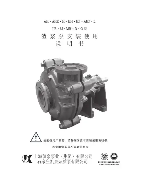
一、概 述卧式渣浆泵为悬臂离心式渣浆泵,适用于输送磨蚀性或腐蚀性渣浆,被广泛用于冶金、矿山、石油、化工、煤炭、电力、交通,河流疏浚,建材及市政工程等部门。
其结构特点,按使用范围可分为以下几种型式;1、 AH、AHP、HP、M、H、HH 型泵,亦可称为重型渣浆泵。
由于该型泵具有较厚的承磨件并配重型托架,故适于输送强磨蚀,高浓度渣浆或低浓度高扬程渣浆,在泵的最大允许工作压力范围之内,可以多级串联使用。
其中HH 型泵适用于输送低浓度高扬程渣浆或高浓度低磨蚀的高扬程渣浆。
以上几种型式的泵亦可用于有一定腐蚀性的渣浆。
2、 L 型泵,亦称为轻型渣浆泵。
与重型渣浆泵相比,该型泵转速高,体积小,重量轻,适用于输送细颗粒,低浓度的渣浆或腐蚀性渣浆。
输送浆体的重量浓度一般不超过30%,亦可用于输送高浓度低磨蚀性渣浆。
3、 D 型挖泥泵及G 型砂砾泵,该型泵具有较大的过流通道,适用于输送砂砾,泥浆及固体颗粒较大的渣浆。
![渣浆泵培训[1]](https://uimg.taocdn.com/d48a8917d1f34693dbef3e24.webp)

一、概述卧式渣浆泵为悬臂离心式渣浆泵,适用于输送磨蚀性或腐蚀性渣浆,被广泛应用于冶金、矿山、石油、化工、煤炭、电力、交通,河流疏浚,建材及市政工程等部门。
其结构特点,按使用范围可分为以下几种型式:1、AH 、AHP、HP、M、H、HH型泵,亦可称为重型渣浆泵。
由于该型泵具有较厚的承磨件并配重型托架,故适于输送强磨蚀,高浓度渣浆或低浓度高扬程渣浆,在泵的最大允许工作压力范围之内,可以多级串联使用。
其中HH型泵适用于输送低浓度高扬程渣浆或高浓度低磨蚀的高扬程渣浆。
以上几种型式的泵亦可用于有一定磨蚀性的渣浆。
2、L型泵,亦称为轻型渣浆泵。
与重型渣浆泵相比,该型泵转速越高,体积小,重量轻,适用于输送细颗粒,低浓度的渣浆或腐蚀性渣浆。
输送浆体的重量浓度一般不超过30%,亦可用于输送高浓度低磨蚀性渣浆。
3、D型挖泥泵及G型砂浆泵,该型泵具有较大的过流通道,适用于输送砂砾,泥浆及固体颗粒较大的渣浆。
4、AHR、LR、MR型泵,该泵过流部件为橡胶材料。
其泵体、泵盖及传动部件等与AH 、L、M型泵通用。
适用于输送细颗粒及腐蚀性渣浆。
型号意义:10 / 8 ST –AHAH型泵(重型渣浆泵)ST型托架出口直径8英寸进口直径10英寸二、结构说明AH、AHP、HP、M、H、HH型泵结构图见图一AHR、MR、LR型泵结构图见图二L型泵结构图见图三D、G型泵结构图见图四以上各种形式卧式渣浆泵除泵头部分(包括泵体、泵盖、叶轮等)结构不同外,其余部分结构相似,采用同一系列的传动部分。
下面按泵头部分、轴封部分及传动部分,分别叙述其结构特点。
1.泵头部分L、M、AH、AHP、HP、H、HH型泵为双泵壳结构,即泵体、泵盖带有可更换的耐磨金属内衬(包括叶轮、护套、护板等)。
泵体、泵盖根据工作压力采用灰铸铁或球墨铸铁制造,垂直中开,用螺栓连接。
泵体有止口与托架用螺栓连接。
泵的吐出口可按八个角度旋转安装。
叶轮前后盖板带有背叶片以减少泄漏及提高泵的使用寿命。
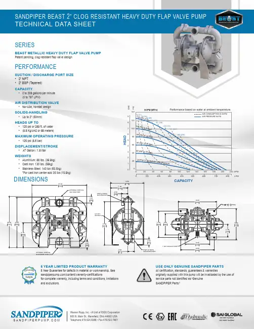
S A N D P I P E R P U M P.C O MWarren Rupp, Inc. • A Unit of IDEX Corporation 800 N. Main St., Mansfield, Ohio 44902 USA Telephone 419.524.8388 • Fax 419.522.78675 YEAR LIMITED PRODUCT WARRANTY5 Year Guarantee for defects in material or workmanship. See /content/warranty-certificationsfor complete warranty, including terms and conditions, limitations and E ONLY GENUINE SANDPIPER PARTS All certification, standards, guarantees & warrantiesoriginally supplied with this pump will be invalidated by the use of service parts not identified as “Genuine SANDPIPER Parts.”AIR DISTRIBUTION VALVE • No-lube, no-stall design SOLIDS-HANDLING • Up to 2” (50mm)HEADS UP TO• 125 psi or 289 ft. of water • (8.8 Kg/cm2 or 88 meters)MAXIMUM OPERATING PRESSURE • 125 psi (8.6 bar)DISPLACEMENT/STROKE • .47 Gallon / 1.8 liter WEIGHTS• Aluminium: 88 lbs. (39.9kg)• Cast Iron: 130 lbs. (59kg)• Stainless Steel: 140 lbs (63.5kg)*For cast iron center add 35 lbs (15.9kg)DIMENSIONSISO 9001 Certified I SO 14001 CertifiedII IIP S IB A R19.875059.8124921.6455020.305162.61662.6166OPTIONAL VERTICAL SUCTION PORTOPTIONAL VERTICAL DISCHARGE PORT2.55652.646717.694492.59667.06179 13.5634413.0033016.0040610.2526014.0035511.00279 8.882265.281348X.5013 THRUS A N D P I P E R P U M P.C O M Warren Rupp, Inc. • A Unit of IDEX Corporation 800 N. Main St., Mansfield, Ohio 44902 USA Telephone 419.524.8388 • Fax 419.522.7867Material Profile:Operating Temperatures:Max.Min.CONDUCTIVE ACETAL: Tough, impact resistant, ductile. Good abrasion resistance and low friction surface. Generally inert, with good chemical resistance except for strong acids and oxidizing agents.190°F 88°C-20°F -29°CEPDM: Shows very good water and chemical resistance. Has poor resistance to oils and solvents, but is fair in ketones and alcohols.280°F 138°C -40°F -40°C F KM (FLUOROCARBON): Shows good resistance to a wide range of oils and solvents; especially all aliphatic, aromatic and halogenated hydrocarbons, acids, animal and vegetable oils. Hot water or hot aqueous solutions (over 70°F(21°C)) will attack FKM.350°F 177°C-40°F -40°CHYTREL ®: Good on acids, bases, amines and glycols at room temperatures only.220°F 104°C -20°F -29°C NEOPRENE: All purpose. Resistance to vegetable oils. Gener-ally not affected by moderate chemicals, fats, greases and many oils and solvents. Generally attacked by strong oxidizing acids, ketones, esters and nitro hydrocarbons and chlorinated aromatic hydrocarbons.200°F 93°C-10°F -23°CNITRILE: General purpose, oil-resistant. Shows good solvent, oil, water and hydraulic fluid resistance. Should not be used with highly polar solvents like acetone and MEK, ozone, chlorinated hydrocarbons and nitro hydrocarbons.190°F 88°C -10°F -23°CNYLON: 6/6 High strength and toughness over a wide tem-perature range. Moderate to good resistance to fuels, oils and chemicals.180°F 82°C 32°F 0°CPOLYPROPYLENE: A thermoplastic polymer. Moderate tensile and flex strength. Resists stong acids and alkali. Attacked by chlorine, fuming nitric acid and other strong oxidizing agents.180°F 82°C 32°F 0°C PVDF: (Polyvinylidene Fluoride) A durable fluoroplastic with excellent chemical resistance. Excellent for UV applications. High tensile strength and impact resistance.250°F 121°C 0°F -18°C SANTOPRENE ®: Injection molded thermoplastic elastomer with no fabric layer. Long mechanical flex life. Excellent abrasion resistance.275°F 135°C -40°F -40°C UHMW PE: A thermoplastic that is highly resistant to a broad range of chemicals. Exhibits outstanding abrasion and impact resistance, along with environmental stress-cracking resistance.180°F 82°C -35°F -37°C URETHANE: Shows good resistance to abrasives. Has poor resistance to most solvents and oils.150°F 66°C 32°F 0°C VIRGIN PTFE: (PFA/TFE) Chemically inert, virtually impervious. Very few chemicals are known to chemically react with PTFE; molten alkali metals, turbulent liquid or gaseous fluorine and a few fluoro-chemicals such as chlorine trifluoride or oxygen difluoride which readily liberate free fluorine at elevated temperatures.220°F 104°C-35°F -37°CMaximum and Minimum Temperatures are the limits for which these materials can be operated. Temperatures coupled with pressure affect the longevity of diaphragm pump components. Maximum life should not be expected at the extreme limits of the temperature ranges.Metals:ALLOY C: Equal to ASTM494 CW-12M-1 specification for nickel and nickel alloy.STAINLESS STEEL: Equal to or exceeding ASTM specification A743 CF-8M for corro-sion resistant iron chromium, iron chromium nickel and nickel based alloy castings for general applications. Commonly referred to as 316 Stainless Steel in the pump industry.For specific applications, always consult the Chemical Resistance Chart.CAUTION! Operating temperature limitations are as follows:EXPLANATION OF PUMP NOMENCLATUREMATERIALSNOTE: See service manual for ATEX details.SP_DS_BeastM_0118(fill in frompump nameplate)Your Model #:Pump Brand Product Line Pump Size Check Valve Type Wetted Material Non-Wetted Material Diaphragm Material Backup Diaphragm Check ValveMaterial Seat Material Air Valve Air Valve Option Exhaust Option Port Type Port Option Design LevelSP B 2000RF S S PUMP BRANDSP SANDPIPERPRODUCT LINEB The Beast FlapPUMP SIZE20 2”CHECK VALVE TYPE FFlap ValveWET END MATERIALSA AluminumI Cast IronP Polypropylene SStainless SteelNON-WETTED MATERIAL A AluminumI Cast Iron P Po l ypropy l eneW White Epoxy Coated AluminumDIAPHRAGM MATERIALB Nitrile (Buna) E EPDM F FDA Nitrile N Neoprene R Santoprene H Hytre l V FKM (Viton)BACKUP DIAPHRAGMNoneCHECK VALVE MATERIALS Stainless Steel SEAT MATERIAL S Stainless SteelAIR VALVESSANDPIPER Standard ESADSAIR VALVE OPTION0 None S Stainless Steel Sleeve & Brass SpoolEXHAUST OPTION 0 Encapsulated Polypropylene 6 Threaded MetalPORT TYPEB BSPTN NPTU Universal ANSI/DIN FlangePORT OPTIONR Center Ported DESIGN LEVEL1Design LevelII 2II 2。
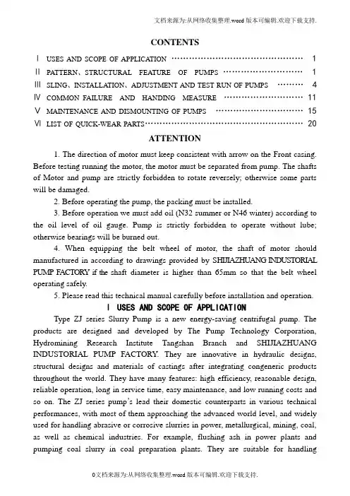
CONTENTSⅠUSES AND SCOPE OF APPLICATION (1)ⅡPATTERN、STRUCTURAL FEATURE OF PUMPS (1)ⅢSLING、INSTALLATION、ADJUSTMENT AND TEST RUN OF PUMPS (4)ⅣCOMMON FAILURE AND HANDING MEASURE (11)ⅤMAINTENANCE AND DISMOUNTING OF PUMPS (15)ⅥLIST OF QUICK-WEAR PARTS (20)ATTENTION1. The direction of motor must keep consistent with arrow on the Front casing. Before testing running the motor, the motor must be separated from pump. The shafts of Motor and pump are strictly forbidden to rotate reversely; otherwise some parts will be damaged.2. Before operating the pump, the packing must be installed.3. Before operation we must add oil (N32 summer or N46 winter) according to the oil level of oil gauge. Pump is strictly forbidden to operate without lube; otherwise bearings will be burned out.4. When equipping the belt wheel of motor, the shaft of motor should manufactured in according to drawings provided by SHIJIAZHUANG INDUSTORIAL PUMP F ACTORY if the shaft diameter is higher than 65mm so that the belt wheel operating safely.5. Please read this technical manual carefully before installation and operation.Ⅰ USES AND SCOPE OF APPLICATIONType ZJ series Slurry Pump is a new energy-saving centrifugal pump. The products are designed and developed by The Pump Technology Corporation, Hydromining Research Institute Tangshan Branch and SHIJIAZHUANG INDUSTORIAL PUMP FACTORY. They are innovative in hydraulic designs, structural designs and materials of castings after integrating congeneric products throughout the world. They have many features: high efficiency, reasonable design, reliable operation, long in service time, easy maintenance, and low running costs and so on. The ZJ series pump’s lead their domestic counterparts in various technical performances, with most of them approaching the advanced world level, and widely used for handling abrasive or corrosive slurries in power, metallurgical, mining, coal, as well as chemical industries. For example, flushing ash in power plants and pumping coal slurry in coal preparation plants. They are suitable for handlingabrasive and corrosive solids-bearing slurry with maximum concentrations of wt.45%(ash) and wt.60%(ore).Ⅱ PATTERN、STRUCTURAL FEATURE OF PUMPSThe ZJ series slurry pumps are single-stage, single-suction, axial-suction and centrifugal slurry pumps. They classified into the horizontal version (ZJ type) and the vertical version (ZJL type).1. Structural feature and type of ZJ slurry pumps(1) Structural feature of ZJ slurry pumpsPump head:It is a horizontal cantilevered slurry double-cases pump. The pump head includes cases, impeller, and shaft seal. Double-cases pump centrally split vertical spilt direction. Discharge port can be positioned at 8 different position at an interval of 45°. The outside cases made by HT200 or HT500-7, connecting with bolts. The inside cases (volute case, front liner, back liner) made by high-chrome alloy or rubber materials.Impeller front and back cover plates with back vanes to reduce leakage and increase operating life, impeller and shaft is firmly connected by ladder-shaped with disassembly ring, ”O” rubber ring is used between liner and volute casing and it is very convenient and reliable.Shaft Seal: expeller seal and packing seal.SupportThe supports can be lubricated by oil. Supports are made up with support body, support cover, shaft, bearing box, bearing, bearing cover, baffle sleeve, nut, oil seal wash plate and so on (See Figure, 1). The supports have water-cooling above 150ZJ.Figure 1Structural Drawing Of ZJ Slurry Pumps1. Coupling2. Shaft3. Bearing housing4. Disassembly ring5. Expeller6. Rear liner plate7. V olute casing 8. Impeller 9. Front liner plate10. Front casing 11.Rear casing 12. Stuffing box13. Water-seal ring 14. Base 15. Support16. Adjusting bolts 17. Inlet stub 18. Outlet stub(2) Type Designation of ZJ slurry pumpsExternal diameter of impeller after incision(cm)Diameter of impeller (cm)Number of vanes of impellerI denotes single stage pumpZJ denotes slurry pumpsOutlet diameter (mm)2. Structural feature and type of ZJL series slurry pumps(1) Structural feature of ZJL series slurry pumpsZJL series slurry pumps are made up of Impeller、V olute casing、Rear line plate、Shaft sleeve、Support、Supporting plate、Shaft、Bearing、Bearing body and so on. The materials of Impeller、V olute casing and Rear line plate is cast iron which contains high-chrome alloy. The impeller can be installed with shaft through screw thread. V olute casing、support and bearing body are connected with bolts. The driving patterns of the shaft and the motor could choose the coupling direct driven or the belt driven. The bearings of ZJL slurry pumps are lubricated by grease. Structure of the ZJL series slurry pumps (See Figure2)(2) Type and meaning of ZJL series slurry pumps80 ZJL —36External diameter of impeller (cm)Vertical version slurry pumpsOutlet diameter (mm)1. V olute casing2. Impeller3. Rear line plate4. Seal ring5. Oil seal6. Bearing7. Oil cupFigure 2 The structural drawing of ZJL series vertical slurry pumpsⅢ SLING、INSTALLATION、ADJUSTMENT AND TEST RUN OF PUMPS1. SlingWhen slinging a packed pump, we operate in accordance with marks on the packing case. The packing case shall avoid vibrating violently, overinclining, landing on the body with pointed ends and being placed upside down.When slinging an unpacked pump, we operate according as the following requirement.(1) When lifting the horizontal pump without base or with singly base, the liftgravity is on the side of support square hole that near the pump head. Wirerope pass through this place to join with lift hook. In order to keep the balance of pump, the auxiliary wirerope should be added between inlet pipeline and lifting screw. The lifting screws on support cover and casings are assembled to dismount support cover and casings. They cannot be used when lift the whole pump in case of accident. (2) When slinging the horizontal pump with motor and common base, the lift gravity is on the side of support square hole that near couplings. Wirerope pass through this place to join with lift hook. In order to keep the balance of pump, the auxiliary wirerope should be installed among inlet pipeline, lifting screws on motor and lift hook.(3) The horizontal pump units with intermediate speed-transformation, such as coupled apparatus, should be lift separately.(4) Cushion should be added between wirerope and body of pump to prevent damaging appearance of pump and cutting off wirerope.2. Installation(1) Examination before installationThe pumps have been inspected and tested before ex-factory. Pumps should be set up correctly in order to possess good operating mode. We must check up types of pumps、parameters of pumps and components and parts in accordance with Packing List before installation. We ensure that technical data and quality certificate of pump is complete. Pump can be installed after reading correlation technical data carefully, especially such as THE INSTRUCTIONS OF INSTALLATION AND APPLICATION FOR TYPE ZJ SLURRY PUMPS and mastering related technical requirements.(2) Installation and capturing of pumpThe horizontal pump units should be equipped by making use of twice grouting. The central line of pumps is consistent with the central line of foundation. The deviation between center-height of pump and design value is smaller than ±2 mm vertically and 0.1/1000 horizontally.We assure axis of pump units by adjusting couplings when pumps are drove by couplings. There are two methods.The first method is the use of knife ruler and plug gauge. We adjust outside diameter of couplings with knife ruler to guarantee alignment in every direction and the max tolerance (δ) less than 0.1 mm [See Figure3,(a)]. We examine the interval between coupling to guarantee the max tolerance △(△=δ1-δ2) smaller than 0.1mm[See Figure3, (b)]. The other method is the use of plug gauge and magnetic centigrade scale. We fix magnetic centigradescale on outside diameter of one coupling and put measuring head on outside diameter of the other coupling. The pulsation of centigrade scale should be smaller than 0.15mm [See Figure3, (c)] when turn rotor. We check up the space between couplings with plug gauge to ensure the max tolerance less than 0.1mm [See Figure3, (b)].(a) (b) (c)Figure 3 Capturing of couplingThe shaft of pump and the motor should assured the parallelism when pumps are drove by belts, so we adjust direction on the basis of pulley. When central distance is small, we can align end faces of pulley with ruler; when central distance is big, and we can adjust them by aligning end faces through span wire system [See Figure, (4)].Figure 4 Capturing of belt wheels(3) Configuration and requirement of discharge pipeline and suction pipeline According to the applied condition and the cavitation performance of pump, the arrangement of pump can be classified into exalted setting [See Figure5, (a)] and low setting [See Figure5, ( b)].(a) (b)Figure 5 Arrangement of suction pipeline and discharge pipeline①Suction pipelineDiameter of suction pipeline: diameter of suction pipeline should be equal to pump inlet or larger than it so as to avoid cavitation and deposition of slurry in pipeline. Gate valve of suction pipeline: In order to maintain easily, we should install inletgate valves whose diameter is equal to the diameter of suction pipeline. The expansion pipe should be set up between inlet of pump and suction pipeline so as to disassemble pump.②Discharge pipelineDiameter of discharge pipeline: diameter of discharge pipeline is usually bigger than outlet of pump because diameter of discharge pipeline is related to properties of slurries and sedimentation flow rate.Gate valve of discharge pipeline: Diameter of outlet gate valve is equal to diameter of discharge pipeline.Piezometer: The piezometer should be set up on the ascending pipe between outlet of pump and the first valve.③Points for configuration of pipelineThe diameter of pipeline is related to system resistance, critical sedimentation velocity of slurry etc. Before inlet of pump, one-stage pipe longer than 3 times diameter of pipeline had better be installed. The velocity of slurry is between 1.5 and 3.0 m/s, which is determined by critical sedimentation velocity of slurry.When we install suction pipe in suction arrangement we adopt pipe of varying diameter whose upper generating line is horizontal to avoid cavitation (See Figure, 6).Figure 6 Reducing pipe with horizontal upper generating lineWhen we adjust the capacity of pump with throttle, throttle should be installed on the discharge pipeline. When throttle is fixed on suction pipeline, cavity will happen easily.(4) Pipelines of water-sealing and water-coolingPacking seal will be equipped with stubs and piezometer. We must install pressure gauge on shaft seal water pipeline to adjust the pressure of shaft seal water. The setting of shaft seal water pipeline and water-cooling pipeline are seen Figure7.Shaft seal water Water-coolingFigure 7 Arrangement of shaft seal water pipelineThe pressure of shaft seal water should be computed according as the following formula.Table 1 Pressure and Capacity of shaft seal waterNote: This Table is suitable to single stage pump.When the suction pressure of pump is 0 (Pin=0), the pressure of shaft seal water is equal to the half of the pressure of pump exit (P’=1/2P out).The pressure of water-cooling is between 0.05~0.2MPa, the capacity is between 1~3 m3/h.The type of water-cooling see Table 2.Table 2 Type of Packing, water-sealing and water-cooling(5)Packing selectionAsbestos packing with mica should be often used when the working pressure of pump is less than 0.5MPa and asbestos packing with ploytetrafluoroethylene should be used when the pressure is more than 0.5 MPa. The type of packing see Table 2. The packing standard should be accord with stuffing box size, and from thedirection of shaft, joints of the adjacent packing rings included 120°.3. Adjustment of pumpWe examine and adjust pumps after assembly.(1) Adjustment of the interval between impeller and front liner (See Following)(2) Adjustment of rotation direction of motorMotor's direction of rotation must be in accordance with pump's direction of rotation. When pump operate in opposite direction, some parts will be damaged. After pumps are divorced from motors completely, we can regulate motor direction of rotation. When they are in the same direction, we attach pumps to motors. We must not start motor blindly.(3) Adjustment of transmissionWhen pumps are drove by elastic pin coupling, protective cover and pins should be set up carefully. When pumps are drove by belt, we adjust sliding track so as that every belt has the same pretightening force and install protective cover attentively. When pumps are drove by speed controllers, they are adjusted according to installation instructions.(4)All of fasteners must be reinforced again.(5) Put the tools and the lumbers aside to avoid accident, which was set on pump units4. Test run of pumpsPump sets can be tested run after adjustment. If possible, slurry can be transported after test run with clear water.(1) Starting of pump①Before starting of pump we must turn the impeller around in the stated direction in order that whether running is flexible.②Switch on shaft seal water. Adjust pressure up to specified value.③Suction valves are opened completely.④Open water-flooding valves to pour the water into pump.⑤Open the outlet valves and adjust the opening degree of valve gate to quarter.⑥Start the pump units. We turn on piezometer on discharge pipeline after speed of rotation was stable. If pressure of discharge pipeline was stable, we can open discharge valves slowly up to required working conditions.Attention:When discharge valves are opened fully, starting pumps will make motor overloaded. Opening suction valves partly will bring about cavity.(2) Notes of pumpAfter operation of pumps normally, we should examine the following①Examine whether the capacity and head of pump stable and fit for requirementof work condition.②Examine whether the electric current of motor is stable.③Examine sound、noise and vibration in pump units is normal or not.④The temperature rise of bearings is under 35℃, but the highest temperature of bearings is lower than 75℃.⑤For packing seal, should open the shaft sealing water and check whether shaft sealing water quantity and water pressure are suitable, adjust the bolts on packing gland so as to adjust packing and shaft sealing water, it is better to leak out drop by drop, if packing is very tight, heating will be produced on the bearing consuming power, if packing is very loose, amount of liquid leakage will be excessive large.(4) Shutting down①Pumping clear water on pump for 30 minutes before shutting down in order to clear any slurry through pump.②Shut off discharge valves.③Close the water of shaft seal and water-cooling.④Shut off suction valves.Attention: we must stop each stage pump at the same time when discharge valves are opened fully, lest water hammer happen and parts will be damaged.Ⅳ COMMON FAILURE AND HANDING MEASURENO.1(1) Appearance of faultyThere is no water in pipeline when pumps operated normally. The pointers of pressure gage and vacuum meter move up and down violently.(2) Analysis of reasona. There is not enough water in suction pipeline.b. Pipeline is blocked up and suction valves are not opened completely.c. There is a serious leakage of air in suction pipeline、apparatus、stuffing box etc.(3) Processing measurea. We fill water into suction pipeline.b. Open suction valves and clean plugging cement in pipeline.c. Stop a leakage of air.NO.2(1) Appearance of faultyThere is no water in pipeline when pumps operate normally. The vacuum metershows high vacuum.(2) Analysis of reasona. The suction valves are closed or stopped up.b. The resistance of pipeline is too big. Pipeline is stopped up.c. The mounting height is too high.(3) Processing measurea. Open suctions valves or clean dirt.b. We improve the suction pipeline design or clean dirt.c. We can lower mounting height.NO.3(1) Appearance of faultyThere is no water in pipeline when pumps operate normally. The pressure gages show a little pressure.(2) Analysis of reasona. The resistance of discharge pipeline is too high.b. Impellers are clogging.c. Rotation speed of pump is smaller.(3) Processing measurea. We examine and adjust discharge pipeline.b. Clean impellers.c. Improve rotation speed of pump.NO.4(1) Appearance of faultyThe pump cannot rotate normally.(2) Analysis of reasona. There are blocks in volutes.b. Outlet valve doesn't closes fully and slurry was put into pump.(3) Processing measurea. Clean dirt in volutes.b. Examine and replace valve and clean dirt.NO. 5(1) Appearance of faultyThe capacity of pump is not enough.(2) Analysis of reasona. Impeller、discharge pipeline、and suction pipeline are blocked up.b. Expellers are worn down.c. Rotation speed of pump is smaller than designed value.e. The resistance of pipeline is too high.f. Suction valves are opened partly.g. Pumps are unfit for working condition.(3) Processing measurea. Clean impellers and pipeline.b. Exchange impellers.c. Readjust rotation speed of pump motors.d. Remount pumps and reduce a leakage of air.e. Lower height of transport. Reduce resistance of pipeline.f. Open suction valves completely.g. Choose pumps again.NO.6(1) Appearance of faultyMotors are overloaded.(2) Analysis of reasona. Delivery head of pump is higher than necessary head, so value of working condition moves to the larger capacity.b. Proportion of slurry is not considered when we choose motors.(3) Processing measurea. Cut down impellers. Bring down rotation speed of pump.b. Choose motor again.NO.7(1) Appearance of faultyThere is no water in pipeline. Sound in pump is abnormal.(2) Analysis of reasona. Resistance of suction pipeline is too high.b. Height of suction is too large.c. Cavitation happens.d. Air goes into suction pipeline.e. The temperature of slurry is high.(3) Processing measurea. Clean suction pipeline and inlet gate valves.b. Bring down height of suction.c. Adjust discharge valves so as that flow of pumps goes into the prescribed limit.d. Reduce the leakage of air.e. Bring down the temperature of slurry.NO.8Pumps vibrate violently.(2) Analysis of reasona. Cavitation happens.b. Expellers are blocked up.c. The shaft of pump and the shaft of motor are not concentric.d. Fastening parts or foundation becomes flexible.(3) Processing measurea. Bring down height of installation. Lessen the resistance of suction pipeline.b. Clean the impellers.c. Readjust central line again.d. Fasten anchor nuts and reinforce ground.NO.9(1) Appearance of faultyBearings have a fever.(2) Analysis of reasona. Cooling water cocks are not opened.b. Bearings cannot be lubricated normally.c. Lubricant oil is not clean.d. The installation direction of thrust bearing is not proper.e. Quality of bearing is not up to standard.(3) Processing measurea. Turn on cooling water.b. Adjust oil level according to specification instructions.c. Clean bearings and replace lubricant oil.d. Determine installation direction of bearing according to direction of pressure.e. Change bearings.NO.10(1)Appearance of faultya. Excessive leakage from stuffing box.b. Packing was burned down.(2) Analysis of reasona. Packing worn.b. No water-sealing(3) Processing measurea. Replace new packing.b. Open the water-sealingNO.11Oil is leaked from pump.(2) Analysis of reasona. Oil level is too high.b. Seal parts loss efficacy.c. Pumps are assembled unreasonably.(3) Processing measurea. Bring down oil level.b. Exchange seal parts.c. Reassemble pumps.NO.12(1) Appearance of faultyWater is leaked from pump head.(2) Analysis of reasona. There are questions in rubber parts.(3) Processing measurea.Press rubber parts or reassemble pumps.Ⅴ MAINTENANCE AND DISMOUNTING OF PUMPSIn order that ZJ series pumps operate safely and play to strong points, maintenance and way of disassemble & assemble is important. According to the feature of the ZJ series pumps, we establish the requirement of maintenance. When the pump is working, must ensure that the packing are installed.1. MaintenanceThe ZJ series pumps have been adjusted before delivery. During 6 months after purchasing customers need not take apart pumps. Before using pumps, we should examine the flexibility of rotation and add lubricant oil.⑴Keep facilities clean、dry、without dirties and leakage.⑵Examine oil level in support every day, its deviation from the oil level of support is ±2 mm⑶Examine operation、vibration and leakage every day. We must solve them in time when we find problems.⑷No operating when pump-out. When operating on that condition, pumps will vibrate violently and reduce service life.⑸Metal body and big block, which cannot pass through pumps, must not enter pumps, neither do rubbers, plastics, and cottons, lest wet parts are damaged and stopped up so as to operate abnormally.⑹We should check up flow and pressure of shaft seal water and cooling waterHigher temperature shows short of water.⑺Examine leakage of shaft seal water regularly. When leakage becomes big we should adjust bolts of stuff cover and exchange stuff in time.⑻Assembly of the packing①The packing length should be accord with sleeve circle, and from the direction of shaft, joints of the adjacent packing rings crossed 120°.②After packing, test run with supplying water, meantime, adjust gland bolts carefully to make the leakage be drop not line. Packing is very important to be pay attention to, it not only related state of seal, but also affect performances of pump.⑼In order to make pumps operate efficiently we must adjust the interval between impeller and front liner so as that it is between 0.75-1.00 mm. The interval has been adjusted before delivery. You can stop pump and adjust it if you find it isn't up to mustard or you find problem in pump's work. Adjust them as following.①Undo nuts of support cover.②Undo adjustable bolt screws.③Tighten nuts of bearing box averagely so as that rotor moves to pump head until rotor cannot rotate. Attention: direction of winding impellers should be in accordance with work direction.④Measure the interval (δ=a) between flange of bearing box and end face of support. Now the interval between impeller and front line is zero.⑤Undo nuts of bearing box.⑥Tighten adjustable screws averagely so as that rotor moves to motor. Check up the interval until it is equal to a+(0.75-1.00mm). Attention: ensure the rotor stated firmly.⑦Tighten nuts of bearing box in order to fix rotor in axial direction.⑽Examine temperature of bearings and ensure it lower than 75℃.⑾Exchange lubricating oil after pumps operate for 800 hours running.⑿Auxiliary pumps rotate the quarter circle weekly so as that shaft of pumps bears static load and vibration of base evenly.⒀If auxiliary pumps are not operating for a long time, we should clean sediment with water before running pumps.⒁Examine supporting mechanism of pipeline regularly so as that supporting is reliable and body of pump does not bear supporting force.⒂Examine fastening parts of base frequently in order that fasting is reliable.⒃Pins can be set up after testing rotor direction of rotation for pumps assembled just now and repaired. Belts can be set up after testing motor direction of rotationloss of power, slurry in pipeline can make impellers rotate oppositely. But when head of pump is above 80m, we should prevent slurry from flowing back lest pumps rotate oppositely.⒄Before starting pumps, we should switch on shaft seal water and cooling water. After stop pumps for 15 minutes, we switch off shaft seal water and cooling water. 2. Assembly、dismantlement and examinationAll elements and parts should be checked up and washed before assembly. We examine if all elements and parts are fit for requirement. After exchanging damaged parts, we assemble pumps.Sequence and requirement of assembling(1) Assembly of rotor partsBearings in the ZJ series Slurry pumps are made in China generally. And the system of lubrication applies to oil.①Assembling of bearinga. Use qualified bearings.b. Examine depth of parallelism and degree of roughness of inner diameter、outer diameter、width and two end faces. Check up flexibility of rotation、rust、stain and so on.c. We should check up the endplay to angle joint bearing and double self-aligning bearings. After we find the center of ball track, we determine whether to add washer and what deep the washer is to guarantee the standard endplay of bearings. Don't assemble radial thrust bearing contrarily.d. When we assemble separable bearings, we should set up them according to marks of inner rings and outer rings in order to avoid assembling them improperly.e. For bearings that can be installed in double direction, we should make the end with marks outward so as to recognize.②Assembly of shafta. To avoid occlusion of seating and damaging axle holes, we should smear oil on seating before installation.b. We install bearings by using hot-pack method. We put bearings into oil into heating apparatus to immerse all seating into oil. We heat the oil to 80-100℃. We should install thermometer in oil to control temperature. After installation, bearings should be cooled down naturally to avoid damaging elements and deforming elements.c. After installing back bearing, we assemble the baffle sleeves and knuckle nuts to press bearing.rotate flexibly. After that, assemble bearing box as hot-pack method.e. Assemble front bearings last as above.f. Fix the seal rings on bearing box.g. After parts of shaft and support are installed, assemble other parts as assembly drawing.⑵Assembly of supportAbove all, clear support cover 、support body’s oil pool and bearing hole.①After we clean the seating between support cover and support body we add paper washer to guarantee bearing holes fit for tolerance of ±0.015mm.②We assemble hexagonal plug screw and oil scale-plate. We scratch a line through the center of oil scale-plate and smear red paint to express oil level.③Assemble cooling parts and cooling cavity covers (Note: Some pumps are not equipped with cooling cavity covers.).④Assembly of parts of shaft and supportLift shaft and put parts of shaft into seating of support. Lift support cover to close support after swearing glue on paper washer. Interval between inner end face of bearing box and end face support is 3mm. We set up taper pin and tighten bolts in advance.⑤Set up oil seal in front bearing cover. After add washer between front bearing cover and end face support, we can tighten bolts.⑥After we examine the interval between back bearing cover and bearing box, we can repair depth of covers and add cushion to let bearing cover leave on the bearing closely. We install oil seal in back bearing cover and tighten bolts after adding cushion between back bearing cover and end face of support.⑦Assemble wash plate and discharge ring. Before assembling discharged ring and pressing wash plate tightly, we should fill grease into screw hole.⑧Assemble adjustable nuts and adapter screw bearing box.⑨Magnetic centigrade scale is equipped with shaft so as to measure coaxality and perpendicularity between locating hole and end faces、shaft center of gyration. The tolerance is smaller than 0.25mm.⑩Assemble coupling or pulley.(3) Assembly of rear casing and rear liner plate①Assemble rear casing on the support.②Assemble sleeve within seal rubber ring on the shaft, then assemble packing gland and water-seal ring on sleeve.③Assemble stuffing box and seal ring in trough, and expeller seal ring and。

ZJ系列渣浆泵使用手册(DOC)目录一、泵的用途和适用范围 (1)二、泵的型式、结构特征与型号 (1)三、泵的起吊、安装、调整与试运行 (3)四、常见故障及处理措施 (14)五、泵的维护保养与拆装 (17)六、易损件明细表 (23)七、专用工具明细表 (24)1特别提示1、必须保证泵轴的转向与泵壳上箭头指示方向一致。
电动机试转时必须与泵完全脱开,严禁电动机带动泵轴反向旋转,否则,将导致零件损坏。
2、采用填料密封的泵,开车前必须按要求填加盘根。
3、采用机械密封的泵,必须保证轴封水的供应。
严禁无水运行,否则机械密封将烧毁。
4、采用稀油润滑的泵,在开车前应按油标的油位线加油。
严禁无油开车,否则,轴承将烧毁。
5、装泵联轴器或泵皮带轮时,为保护机械密封不致因冲击力受损,必须先打入泵联轴器或泵皮带轮后,才能装入机械密封。
否则锺击力有可能导致机械密封动、静环破裂。
6、顾客现场安装电动机皮带轮,当轴径≥65mm时,应按我厂提供轴端加工图及附件钻孔、攻丝、安装轴端挡圈,以确保皮带轮运行安全。
7、安装使用前,请详细阅读此说明书。
2一、泵的用途和适用范围ZJ系列渣浆泵是石家庄工业泵厂与中国煤科院唐山分院联合开发的新型高效节能抗磨蚀泵。
该系列泵在水力设计、结构设计以及所用耐磨材料上,综合应用了国内外同类产品的优点并加以创新,具有高效节能、振动小、噪声低、运行可靠、使用寿命长、维修方便等特点,泵的综合性能居国内领先水平,大部分泵的效率指标居国际先进水平。
可广泛用于电力、冶金、煤炭、建材等行业输送含有固体颗粒的浆体。
如火电厂水力除灰、冶金选矿厂矿浆输送、洗煤厂煤浆及重介输送等。
其允许输送的最大浆体重量浓度Cw为:灰(渣)浆和煤浆45%;矿浆和重介60%。
9二、泵的型式、结构特征与型号ZJ系列渣浆泵的型式分两大类,一类是ZJ型,为卧式轴向吸入单级单吸离心式渣浆泵;另一类是ZJL型,为立式轴向吸入单级单吸离心式渣浆泵。
1.ZJ型渣浆泵的结构特征与型号(1)ZJ型渣浆泵的结构特征①泵头部分ZJ型渣浆泵的泵头部分包括泵壳、叶轮和轴封装置。
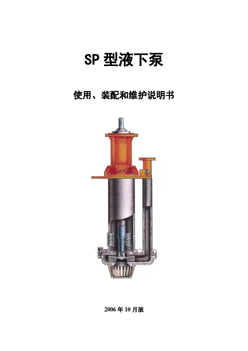
SP型液下泵使用、装配和维护说明书2006年10月版安全须知(一)泵是一种即承压又传动的机器,在安装、操作和维修前及安装操作和维修期间,必须遵守所规定的安全措施。
辅机(如电机、皮带传动装置、联轴器、高速箱、无级变速装置等等)也要遵守这项安全措施,并在安装、操作和维修前参考有关规程。
(二)装皮带或联轴器之前,必须检查转动方向,因为不正确的转动方向将使泵在运转中损坏或个别零件的损坏。
(三)未经专门人员许可,不得使泵超出原来销售时规定的工况运转,否则将导致设备或人身事故。
(四)泵不可在较低或零流量点或在其他可能引起泵送介质汽化的情况下运转,否则将因为压力巨增而可能造成设备人身事故。
(五)维修或泵送期间,内部真空的泵必须隔离,如果不能完好隔离,可能使叶轮变为“飞轮”,从而造成设备和人身事故。
注释应备有包括液池、泵送管路、阀门、控制装置等等在内的系列安装图,以免错装给泵带来不利影响。
目录1、泵的标志 (3)2、泵的装配 (3)3、基础 (3)4、轴的找平 (3)5、管路 (3)6、启动 (3)7、维护保养 (4)8、备件 (4)9、零件的标记 (5)10、润滑剂 (6)为保证泵长期安全工作,泵的使用必须适合于说明书的要求。
1、泵的标志每台液下泵有一个铭牌固定在轴承体上,泵的编号和标志号压印在铭牌上。
(b)、第一个字母指托架规格,托架包括轴承组件和轴。
(c)、这个字母表明轴结构型式。
并用字母“V”指出泵轴是立式运转。
(d)、这第三和第四个字母“SP”表明泵是一种液下泵。
即把泵安装在地面上的槽罐中或地下井坑中,泵头浸没在抽吸的液体中。
2、泵的装配——参阅立式轴承组件装配说明书和泵装配说明书。
3、基础把泵安装在合适的基础上才能达到好的使用效果。
钢架基础要坚固耐用,而混凝土基础要有足够厚度,才能稳定可靠和承受泵和电机的全部载荷,消除振动。
要拧紧所有的地脚螺母。
4、轴的同心找正不管是直联传动还是三角皮带传动,泵轴与电机轴都要准确地同心,在直联传动中,不同心的轴会产生不必要的振动,使联轴器和轴承磨损。
CONTENTSⅠUSES AND SCOPE OF APPLICATION (1)ⅡPATTERN、STRUCTURAL FEATURE OF PUMPS (1)ⅢSLING、INSTALLATION、ADJUSTMENT AND TEST RUN OF PUMPS (4)ⅣCOMMON FAILURE AND HANDING MEASURE (11)ⅤMAINTENANCE AND DISMOUNTING OF PUMPS (15)ⅥLIST OF QUICK-WEAR PARTS (20)ATTENTION1. The direction of motor must keep consistent with arrow on the Front casing. Before testing running the motor, the motor must be separated from pump. The shafts of Motor and pump are strictly forbidden to rotate reversely; otherwise some parts will be damaged.2. Before operating the pump, the packing must be installed.3. Before operation we must add oil (N32 summer or N46 winter) according to the oil level of oil gauge. Pump is strictly forbidden to operate without lube; otherwise bearings will be burned out.4. When equipping the belt wheel of motor, the shaft of motor should manufactured in according to drawings provided by SHIJIAZHUANG INDUSTORIAL PUMP F ACTORY if the shaft diameter is higher than 65mm so that the belt wheel operating safely.5. Please read this technical manual carefully before installation and operation.Ⅰ USES AND SCOPE OF APPLICATIONType ZJ series Slurry Pump is a new energy-saving centrifugal pump. The products are designed and developed by The Pump Technology Corporation, Hydromining Research Institute Tangshan Branch and SHIJIAZHUANG INDUSTORIAL PUMP FACTORY. They are innovative in hydraulic designs, structural designs and materials of castings after integrating congeneric products throughout the world. They have many features: high efficiency, reasonable design, reliable operation, long in service time, easy maintenance, and low running costs and so on. The ZJ series pump’s lead their domestic counterparts in various technical performances, with most of them approaching the advanced world level, and widely used for handling abrasive or corrosive slurries in power, metallurgical, mining, coal, as well as chemical industries. For example, flushing ash in power plants and pumping coal slurry in coal preparation plants. They are suitable for handling abrasive and corrosive solids-bearing slurry with maximum concentrations of wt.45%(ash) and wt.60%(ore).Ⅱ PATTERN、STRUCTURAL FEATURE OF PUMPSThe ZJ series slurry pumps are single-stage, single-suction, axial-suction and centrifugal slurry pumps. They classified into the horizontal version (ZJ type) and the vertical version (ZJL type).1. Structural feature and type of ZJ slurry pumps(1) Structural feature of ZJ slurry pumpsPump head:It is a horizontal cantilevered slurry double-cases pump. The pump head includes cases, impeller, and shaft seal. Double-cases pump centrally split vertical spilt direction. Discharge port can be positioned at 8 different position at an interval of 45°. The outside cases made by HT200 or HT500-7, connecting with bolts. The inside cases (volute case, front liner, back liner) made by high-chrome alloy or rubber materials.Impeller front and back cover plates with back vanes to reduce leakage and increase operating life, impeller and shaft is firmly connected by ladder-shaped with disassembly ring, ”O” rubber ring is used between liner and volute casing and it is very convenient and reliable.Shaft Seal: expeller seal and packing seal.SupportThe supports can be lubricated by oil. Supports are made up with support body, support cover, shaft, bearing box, bearing, bearing cover, baffle sleeve, nut, oil sealwash plate and so on (See Figure, 1). The supports have water-cooling above 150ZJ.Figure 1Structural Drawing Of ZJ Slurry Pumps1. Coupling2. Shaft3. Bearing housing4. Disassembly ring5. Expeller6. Rear liner plate7. V olute casing 8. Impeller 9. Front liner plate10. Front casing 11.Rear casing 12. Stuffing box13. Water-seal ring 14. Base 15. Support16. Adjusting bolts 17. Inlet stub 18. Outlet stub(2) Type Designation of ZJ slurry pumpsExternal diameter of impeller after incision(cm)Diameter of impeller (cm)Number of vanes of impellerI denotes single stage pumpZJ denotes slurry pumpsOutlet diameter (mm)2. Structural feature and type of ZJL series slurry pumps(1) Structural feature of ZJL series slurry pumpsZJL series slurry pumps are made up of Impeller、V olute casing、Rear line plate、Shaft sleeve、Support、Supporting plate、Shaft、Bearing、Bearing body and so on. The materials of Impeller、V olute casing and Rear line plate is cast iron which contains high-chrome alloy. The impeller can be installed with shaft through screw thread. V olute casing、support and bearing body are connected with bolts. The driving patterns of the shaft and the motor could choose the coupling direct driven or the belt driven. The bearings of ZJL slurry pumps are lubricated by grease. Structure of the ZJL series slurry pumps (See Figure2)(2) Type and meaning of ZJL series slurry pumps80 ZJL —36External diameter of impeller (cm)Vertical version slurry pumpsOutlet diameter (mm)1. V olute casing2. Impeller3. Rear line plate4. Seal ring5. Oil seal6. Bearing7. Oil cupFigure 2 The structural drawing of ZJL series vertical slurry pumpsⅢ SLING、INSTALLATION、ADJUSTMENT AND TEST RUN OF PUMPS1. SlingWhen slinging a packed pump, we operate in accordance with marks on the packing case. The packing case shall avoid vibrating violently, overinclining, landing on the body with pointed ends and being placed upside down.When slinging an unpacked pump, we operate according as the following requirement.(1) When lifting the horizontal pump without base or with singly base, the lift gravity is on the side of support square hole that near the pump head. Wirerope pass through this place to join with lift hook. In order to keep the balance of pump, the auxiliary wirerope should be added between inlet pipeline and lifting screw. The lifting screws on support cover and casings are assembled to dismount support cover and casings. They cannot be used when lift the whole pump in case of accident. (2) When slinging the horizontal pump with motor and common base, the lift gravity is on the side of support square hole that near couplings. Wirerope pass through this place to join with lift hook. In order to keep the balance of pump, the auxiliary wirerope should be installed among inlet pipeline, lifting screws on motor and lift hook.(3) The horizontal pump units with intermediate speed-transformation, such as coupled apparatus, should be lift separately.(4) Cushion should be added between wirerope and body of pump to prevent damaging appearance of pump and cutting off wirerope.2. Installation(1) Examination before installationThe pumps have been inspected and tested before ex-factory. Pumps should be set up correctly in order to possess good operating mode. We must check up types of pumps、parameters of pumps and components and parts in accordance with Packing List before installation. We ensure that technical data and quality certificate of pump is complete. Pump can be installed after reading correlation technical data carefully, especially such as THE INSTRUCTIONS OF INSTALLATION AND APPLICATION FOR TYPE ZJ SLURRY PUMPS and mastering related technical requirements.(2) Installation and capturing of pumpThe horizontal pump units should be equipped by making use of twice grouting. The central line of pumps is consistent with the central line of foundation. Thedeviation between center-height of pump and design value is smaller than ±2 mm vertically and 0.1/1000 horizontally.We assure axis of pump units by adjusting couplings when pumps are drove by couplings. There are two methods.The first method is the use of knife ruler and plug gauge. We adjust outside diameter of couplings with knife ruler to guarantee alignment in every direction and the max tolerance (δ) less than 0.1 mm [See Figure3,(a)]. We examine the interval between coupling to guarantee the max tolerance △(△=δ1-δ2) smaller than 0.1mm[See Figure3, (b)]. The other method is the use of plug gauge and magnetic centigrade scale. We fix magnetic centigrade scale on outside diameter of one coupling and put measuring head on outside diameter of the other coupling. The pulsation of centigrade scale should be smaller than 0.15mm [See Figure3, (c)] when turn rotor. We check up the space between couplings with plug gauge to ensure the max tolerance less than 0.1mm [See Figure3, (b)].(a) (b) (c)Figure 3 Capturing of couplingThe shaft of pump and the motor should assured the parallelism when pumps are drove by belts, so we adjust direction on the basis of pulley. When central distance is small, we can align end faces of pulley with ruler; when central distance is big, and we can adjust them by aligning end faces through span wire system [See Figure, (4)].Figure 4 Capturing of belt wheels(3) Configuration and requirement of discharge pipeline and suction pipeline According to the applied condition and the cavitation performance of pump, the arrangement of pump can be classified into exalted setting [See Figure5, (a)] and low setting [See Figure5, ( b)].(a) (b)Figure 5 Arrangement of suction pipeline and discharge pipeline①Suction pipelineDiameter of suction pipeline: diameter of suction pipeline should be equal to pump inlet or larger than it so as to avoid cavitation and deposition of slurry in pipeline. Gate valve of suction pipeline: In order to maintain easily, we should install inlet gate valves whose diameter is equal to the diameter of suction pipeline. The expansion pipe should be set up between inlet of pump and suction pipeline so as to disassemble pump.②Discharge pipelineDiameter of discharge pipeline: diameter of discharge pipeline is usually bigger than outlet of pump because diameter of discharge pipeline is related to properties of slurries and sedimentation flow rate.Gate valve of discharge pipeline: Diameter of outlet gate valve is equal to diameter of discharge pipeline.Piezometer: The piezometer should be set up on the ascending pipe between outlet of pump and the first valve.③Points for configuration of pipelineThe diameter of pipeline is related to system resistance, critical sedimentation velocity of slurry etc. Before inlet of pump, one-stage pipe longer than 3 times diameter of pipeline had better be installed. The velocity of slurry is between 1.5 and 3.0 m/s, which is determined by critical sedimentation velocity of slurry.When we install suction pipe in suction arrangement we adopt pipe of varying diameter whose upper generating line is horizontal to avoid cavitation (See Figure, 6).Figure 6 Reducing pipe with horizontal upper generating lineWhen we adjust the capacity of pump with throttle, throttle should be installed on the discharge pipeline. When throttle is fixed on suction pipeline, cavity will happen easily.(4) Pipelines of water-sealing and water-coolingPacking seal will be equipped with stubs and piezometer. We must install pressure gauge on shaft seal water pipeline to adjust the pressure of shaft seal water. The setting of shaft seal water pipeline and water-cooling pipeline are seen Figure7.Shaft seal water Water-coolingFigure 7 Arrangement of shaft seal water pipelineThe pressure of shaft seal water should be computed according as the following formula.Table 1 Pressure and Capacity of shaft seal waterNote: This Table is suitable to single stage pump.When the suction pressure of pump is 0 (Pin=0), the pressure of shaft seal water is equal to the half of the pressure of pump exit (P’=1/2P out).The pressure of water-cooling is between 0.05~0.2MPa, the capacity is between 1~3 m3/h.The type of water-cooling see Table 2.Table 2 Type of Packing, water-sealing and water-cooling(5)Packing selectionAsbestos packing with mica should be often used when the working pressure of pump is less than 0.5MPa and asbestos packing with ploytetrafluoroethylene should be used when the pressure is more than 0.5 MPa. The type of packing see Table 2. The packing standard should be accord with stuffing box size, and from the direction of shaft, joints of the adjacent packing rings included 120°.3. Adjustment of pumpWe examine and adjust pumps after assembly.(1) Adjustment of the interval between impeller and front liner (See Following)(2) Adjustment of rotation direction of motorMotor's direction of rotation must be in accordance with pump's direction of rotation. When pump operate in opposite direction, some parts will be damaged. After pumps are divorced from motors completely, we can regulate motor direction of rotation. When they are in the same direction, we attach pumps to motors. We must not start motor blindly.(3) Adjustment of transmissionWhen pumps are drove by elastic pin coupling, protective cover and pins should be set up carefully. When pumps are drove by belt, we adjust sliding track so as that every belt has the same pretightening force and install protective cover attentively. When pumps are drove by speed controllers, they are adjusted according to installation instructions.(4)All of fasteners must be reinforced again.(5) Put the tools and the lumbers aside to avoid accident, which was set on pump units4. Test run of pumpsPump sets can be tested run after adjustment. If possible, slurry can be transported after test run with clear water.(1) Starting of pump①Before starting of pump we must turn the impeller around in the stated direction in order that whether running is flexible.②Switch on shaft seal water. Adjust pressure up to specified value.③Suction valves are opened completely.④Open water-flooding valves to pour the water into pump.⑤Open the outlet valves and adjust the opening degree of valve gate to quarter.⑥Start the pump units. We turn on piezometer on discharge pipeline after speed of rotation was stable. If pressure of discharge pipeline was stable, we can open discharge valves slowly up to required working conditions.Attention:When discharge valves are opened fully, starting pumps will make motor overloaded. Opening suction valves partly will bring about cavity.(2) Notes of pumpAfter operation of pumps normally, we should examine the followingof work condition.②Examine whether the electric current of motor is stable.③Examine sound、noise and vibration in pump units is normal or not.④The temperature rise of bearings is under 35℃, but the highest temperature of bearings is lower than 75℃.⑤For packing seal, should open the shaft sealing water and check whether shaft sealing water quantity and water pressure are suitable, adjust the bolts on packing gland so as to adjust packing and shaft sealing water, it is better to leak out drop by drop, if packing is very tight, heating will be produced on the bearing consuming power, if packing is very loose, amount of liquid leakage will be excessive large.(4) Shutting down①Pumping clear water on pump for 30 minutes before shutting down in order to clear any slurry through pump.②Shut off discharge valves.③Close the water of shaft seal and water-cooling.④Shut off suction valves.Attention: we must stop each stage pump at the same time when discharge valves are opened fully, lest water hammer happen and parts will be damaged.Ⅳ COMMON FAILURE AND HANDING MEASURENO.1(1) Appearance of faultyThere is no water in pipeline when pumps operated normally. The pointers of pressure gage and vacuum meter move up and down violently.(2) Analysis of reasona. There is not enough water in suction pipeline.b. Pipeline is blocked up and suction valves are not opened completely.c. There is a serious leakage of air in suction pipeline、apparatus、stuffing box etc.(3) Processing measurea. We fill water into suction pipeline.b. Open suction valves and clean plugging cement in pipeline.c. Stop a leakage of air.NO.2(1) Appearance of faultyThere is no water in pipeline when pumps operate normally. The vacuum metershows high vacuum.(2) Analysis of reasona. The suction valves are closed or stopped up.b. The resistance of pipeline is too big. Pipeline is stopped up.c. The mounting height is too high.(3) Processing measurea. Open suctions valves or clean dirt.b. We improve the suction pipeline design or clean dirt.c. We can lower mounting height.NO.3(1) Appearance of faultyThere is no water in pipeline when pumps operate normally. The pressure gages show a little pressure.(2) Analysis of reasona. The resistance of discharge pipeline is too high.b. Impellers are clogging.c. Rotation speed of pump is smaller.(3) Processing measurea. We examine and adjust discharge pipeline.b. Clean impellers.c. Improve rotation speed of pump.NO.4(1) Appearance of faultyThe pump cannot rotate normally.(2) Analysis of reasona. There are blocks in volutes.b. Outlet valve doesn't closes fully and slurry was put into pump.(3) Processing measurea. Clean dirt in volutes.b. Examine and replace valve and clean dirt.NO. 5(1) Appearance of faultyThe capacity of pump is not enough.(2) Analysis of reasona. Impeller、discharge pipeline、and suction pipeline are blocked up.b. Expellers are worn down.c. Rotation speed of pump is smaller than designed value.e. The resistance of pipeline is too high.f. Suction valves are opened partly.g. Pumps are unfit for working condition.(3) Processing measurea. Clean impellers and pipeline.b. Exchange impellers.c. Readjust rotation speed of pump motors.d. Remount pumps and reduce a leakage of air.e. Lower height of transport. Reduce resistance of pipeline.f. Open suction valves completely.g. Choose pumps again.NO.6(1) Appearance of faultyMotors are overloaded.(2) Analysis of reasona. Delivery head of pump is higher than necessary head, so value of working condition moves to the larger capacity.b. Proportion of slurry is not considered when we choose motors.(3) Processing measurea. Cut down impellers. Bring down rotation speed of pump.b. Choose motor again.NO.7(1) Appearance of faultyThere is no water in pipeline. Sound in pump is abnormal.(2) Analysis of reasona. Resistance of suction pipeline is too high.b. Height of suction is too large.c. Cavitation happens.d. Air goes into suction pipeline.e. The temperature of slurry is high.(3) Processing measurea. Clean suction pipeline and inlet gate valves.b. Bring down height of suction.c. Adjust discharge valves so as that flow of pumps goes into the prescribed limit.d. Reduce the leakage of air.e. Bring down the temperature of slurry.NO.8Pumps vibrate violently.(2) Analysis of reasona. Cavitation happens.b. Expellers are blocked up.c. The shaft of pump and the shaft of motor are not concentric.d. Fastening parts or foundation becomes flexible.(3) Processing measurea. Bring down height of installation. Lessen the resistance of suction pipeline.b. Clean the impellers.c. Readjust central line again.d. Fasten anchor nuts and reinforce ground.NO.9(1) Appearance of faultyBearings have a fever.(2) Analysis of reasona. Cooling water cocks are not opened.b. Bearings cannot be lubricated normally.c. Lubricant oil is not clean.d. The installation direction of thrust bearing is not proper.e. Quality of bearing is not up to standard.(3) Processing measurea. Turn on cooling water.b. Adjust oil level according to specification instructions.c. Clean bearings and replace lubricant oil.d. Determine installation direction of bearing according to direction of pressure.e. Change bearings.NO.10(1)Appearance of faultya. Excessive leakage from stuffing box.b. Packing was burned down.(2) Analysis of reasona. Packing worn.b. No water-sealing(3) Processing measurea. Replace new packing.b. Open the water-sealingNO.11Oil is leaked from pump.(2) Analysis of reasona. Oil level is too high.b. Seal parts loss efficacy.c. Pumps are assembled unreasonably.(3) Processing measurea. Bring down oil level.b. Exchange seal parts.c. Reassemble pumps.NO.12(1) Appearance of faultyWater is leaked from pump head.(2) Analysis of reasona. There are questions in rubber parts.(3) Processing measurea.Press rubber parts or reassemble pumps.Ⅴ MAINTENANCE AND DISMOUNTING OF PUMPSIn order that ZJ series pumps operate safely and play to strong points, maintenance and way of disassemble & assemble is important. According to the feature of the ZJ series pumps, we establish the requirement of maintenance. When the pump is working, must ensure that the packing are installed.1. MaintenanceThe ZJ series pumps have been adjusted before delivery. During 6 months after purchasing customers need not take apart pumps. Before using pumps, we should examine the flexibility of rotation and add lubricant oil.⑪Keep facilities clean、dry、without dirties and leakage.⑫Examine oil level in support every day, its deviation from the oil level of support is ±2 mm⑬Examine operation、vibration and leakage every day. We must solve them in time when we find problems.⑭No operating when pump-out. When operating on that condition, pumps will vibrate violently and reduce service life.⑮Metal body and big block, which cannot pass through pumps, must not enter pumps, neither do rubbers, plastics, and cottons, lest wet parts are damaged and stopped up so as to operate abnormally.⑯We should check up flow and pressure of shaft seal water and cooling waterand oil by examining position of valves and taking their temperature of stuff box. Higher temperature shows short of water.⑰Examine leakage of shaft seal water regularly. When leakage becomes big we should adjust bolts of stuff cover and exchange stuff in time.⑱Assembly of the packing①The packing length should be accord with sleeve circle, and from the direction of shaft, joints of the adjacent packing rings crossed 120°.②After packing, test run with supplying water, meantime, adjust gland bolts carefully to make the leakage be drop not line. Packing is very important to be pay attention to, it not only related state of seal, but also affect performances of pump.⑲In order to make pumps operate efficiently we must adjust the interval between impeller and front liner so as that it is between 0.75-1.00 mm. The interval has been adjusted before delivery. You can stop pump and adjust it if you find it isn't up to mustard or you find problem in pump's work. Adjust them as following.①Undo nuts of support cover.②Undo adjustable bolt screws.③Tighten nuts of bearing box averagely so as that rotor moves to pump head until rotor cannot rotate. Attention: direction of winding impellers should be in accordance with work direction.④Measure the interval (δ=a) between flange of bearing box and end face of support. Now the interval between impeller and front line is zero.⑤Undo nuts of bearing box.⑥Tighten adjustable screws averagely so as that rotor moves to motor. Check up the interval until it is equal to a+(0.75-1.00mm). Attention: ensure the rotor stated firmly.⑦Tighten nuts of bearing box in order to fix rotor in axial direction.⑳Examine temperature of bearings and ensure it lower than 75℃.⑴Exchange lubricating oil after pumps operate for 800 hours running.⑵Auxiliary pumps rotate the quarter circle weekly so as that shaft of pumps bears static load and vibration of base evenly.⑶If auxiliary pumps are not operating for a long time, we should clean sediment with water before running pumps.⑷Examine supporting mechanism of pipeline regularly so as that supporting is reliable and body of pump does not bear supporting force.⑸Examine fastening parts of base frequently in order that fasting is reliable.⑹Pins can be set up after testing rotor direction of rotation for pumps assembledwhen pumps are drove by belts. Pumps must not rotate oppositely. When motors are loss of power, slurry in pipeline can make impellers rotate oppositely. But when head of pump is above 80m, we should prevent slurry from flowing back lest pumps rotate oppositely.⑺Before starting pumps, we should switch on shaft seal water and cooling water. After stop pumps for 15 minutes, we switch off shaft seal water and cooling water. 2. Assembly、dismantlement and examinationAll elements and parts should be checked up and washed before assembly. We examine if all elements and parts are fit for requirement. After exchanging damaged parts, we assemble pumps.Sequence and requirement of assembling(1) Assembly of rotor partsBearings in the ZJ series Slurry pumps are made in China generally. And the system of lubrication applies to oil.①Assembling of bearinga. Use qualified bearings.b. Examine depth of parallelism and degree of roughness of inner diameter、outer diameter、width and two end faces. Check up flexibility of rotation、rust、stain and so on.c. We should check up the endplay to angle joint bearing and double self-aligning bearings. After we find the center of ball track, we determine whether to add washer and what deep the washer is to guarantee the standard endplay of bearings. Don't assemble radial thrust bearing contrarily.d. When we assemble separable bearings, we should set up them according to marks of inner rings and outer rings in order to avoid assembling them improperly.e. For bearings that can be installed in double direction, we should make the end with marks outward so as to recognize.②Assembly of shafta. To avoid occlusion of seating and damaging axle holes, we should smear oil on seating before installation.b. We install bearings by using hot-pack method. We put bearings into oil into heating apparatus to immerse all seating into oil. We heat the oil to 80-100℃. We should install thermometer in oil to control temperature. After installation, bearings should be cooled down naturally to avoid damaging elements and deforming elements.c. After installing back bearing, we assemble the baffle sleeves and knuckle nuts tod. After examining whether bearings lean on shaft shoulder and whether bearings rotate flexibly. After that, assemble bearing box as hot-pack method.e. Assemble front bearings last as above.f. Fix the seal rings on bearing box.g. After parts of shaft and support are installed, assemble other parts as assembly drawing.⑫Assembly of supportAbove all, clear support cover 、support body’s oil pool and bearing hole.①After we clean the seating between support cover and support body we add paper washer to guarantee bearing holes fit for tolerance of ±0.015mm.②We assemble hexagonal plug screw and oil scale-plate. We scratch a line through the center of oil scale-plate and smear red paint to express oil level.③Assemble cooling parts and cooling cavity covers (Note: Some pumps are not equipped with cooling cavity covers.).④Assembly of parts of shaft and supportLift shaft and put parts of shaft into seating of support. Lift support cover to close support after swearing glue on paper washer. Interval between inner end face of bearing box and end face support is 3mm. We set up taper pin and tighten bolts in advance.⑤Set up oil seal in front bearing cover. After add washer between front bearing cover and end face support, we can tighten bolts.⑥After we examine the interval between back bearing cover and bearing box, we can repair depth of covers and add cushion to let bearing cover leave on the bearing closely. We install oil seal in back bearing cover and tighten bolts after adding cushion between back bearing cover and end face of support.⑦Assemble wash plate and discharge ring. Before assembling discharged ring and pressing wash plate tightly, we should fill grease into screw hole.⑧Assemble adjustable nuts and adapter screw bearing box.⑨Magnetic centigrade scale is equipped with shaft so as to measure coaxality and perpendicularity between locating hole and end faces、shaft center of gyration. The tolerance is smaller than 0.25mm.⑩Assemble coupling or pulley.(3) Assembly of rear casing and rear liner plate①Assemble rear casing on the support.②Assemble sleeve within seal rubber ring on the shaft, then assemble packing gland and water-seal ring on sleeve.。
1.概述ZGB(P)系列渣浆泵是我厂针对除灰除渣工况特点,在多年渣浆泵设计制造经验基础上,广泛吸取国内外先进技术和研究成果,自行开发设计的新型产品。
该系列产品具有结构合理、效率高、寿命长、可靠性高、维修方便、运行费用低等显著优点,广泛用于电力、冶金、矿山、煤炭、建材、化工等工业部门输送含有磨蚀或腐蚀性的渣浆,特别适用于电厂灰渣输送。
泵型号意义:例如:多级串联(3-4)级(1、2级无标记)系列代号高扬程渣浆泵吐出口直径(mm)2.结构说明ZGB(P)系列渣浆泵结构相似,均为卧式、单级、单吸、悬臂双泵壳离心式,其结构特点分泵头部分、轴封部分、传动部分作分别说明。
2.1泵头部分ZGB(P)系列渣浆泵为双泵壳结构,即泵体、泵盖带有可更换的耐磨金属内衬(包括护套、护板等),如图1和图2所示。
泵体、泵盖根据工作压力采用灰铸铁或球墨铸铁制造。
该系列泵均为垂直中开式,吐出口方向可按450间隔八个角度旋转安装。
叶轮前后盖板设有付叶轮以减少泄漏及提高泵的使用寿命。
该系列进口均为水平方向,从传动端看泵为顺时针旋转。
起动及运转时,严禁电机反方向旋转。
否则,将使泵叶轮脱落造成事故。
2.2 轴封部分轴封有两种型式:(1) 付叶轮加填料组合式密封:该种密封型式是我厂采用可靠性设计研制的高性能密封,它使轴封的泄漏减少到了最小。
针对某些不允许稀释、不允许加轴封水的特殊工况(单级)也能正常工作,并达到无任何泄漏的效果。
付叶轮、减压盖、轴套均采用耐磨材料制造,维修量少、使用寿命长,使整机平均无故障工作时间MTBF大大提高。
(2) 机械密封:该形式的密封特别适用于多级串联渣浆泵的密封,完全无泄漏。
凡串联渣浆泵二级及二级以上,建议采用高压轴封水的机械密封,单级采用付叶轮加填料组合式密封。
2.3轴封水压对于单级(或串联一级)采用填料加付叶轮组合式密封,轴封水压力一般不低于0.2Mpa。
对于多级串联采用填料加付叶轮组合式密封,二级和二级以上轴封水压力一般为:n-1第n 级轴封水最低压力=∑ Hi + 0.7Hn, 其中n≥2i=1对采用机械密封,各级泵的轴封水压力一般要求比泵出口压力大0.1Mpa。
一、概述卧式渣浆泵为悬臂离心式渣浆泵,适用于输送磨蚀性或腐蚀性渣浆,被广泛应用于冶金、矿山、石油、化工、煤炭、电力、交通,河流疏浚,建材及市政工程等部门。
其结构特点,按使用范围可分为以下几种型式:1、AH 、AHP、HP、M、H、HH型泵,亦可称为重型渣浆泵。
由于该型泵具有较厚的承磨件并配重型托架,故适于输送强磨蚀,高浓度渣浆或低浓度高扬程渣浆,在泵的最大允许工作压力范围之内,可以多级串联使用。
其中HH型泵适用于输送低浓度高扬程渣浆或高浓度低磨蚀的高扬程渣浆。
以上几种型式的泵亦可用于有一定磨蚀性的渣浆。
2、L型泵,亦称为轻型渣浆泵。
与重型渣浆泵相比,该型泵转速越高,体积小,重量轻,适用于输送细颗粒,低浓度的渣浆或腐蚀性渣浆。
输送浆体的重量浓度一般不超过30%,亦可用于输送高浓度低磨蚀性渣浆。
3、D型挖泥泵及G型砂浆泵,该型泵具有较大的过流通道,适用于输送砂砾,泥浆及固体颗粒较大的渣浆。
4、AHR、LR、MR型泵,该泵过流部件为橡胶材料。
其泵体、泵盖及传动部件等与AH 、L、M型泵通用。
适用于输送细颗粒及腐蚀性渣浆。
型号意义:10 / 8 ST –AHAH型泵(重型渣浆泵)ST型托架出口直径8英寸进口直径10英寸二、结构说明AH、AHP、HP、M、H、HH型泵结构图见图一AHR、MR、LR型泵结构图见图二L型泵结构图见图三D、G型泵结构图见图四以上各种形式卧式渣浆泵除泵头部分(包括泵体、泵盖、叶轮等)结构不同外,其余部分结构相似,采用同一系列的传动部分。
下面按泵头部分、轴封部分及传动部分,分别叙述其结构特点。
1.泵头部分L、M、AH、AHP、HP、H、HH型泵为双泵壳结构,即泵体、泵盖带有可更换的耐磨金属内衬(包括叶轮、护套、护板等)。
泵体、泵盖根据工作压力采用灰铸铁或球墨铸铁制造,垂直中开,用螺栓连接。
泵体有止口与托架用螺栓连接。
泵的吐出口可按八个角度旋转安装。
叶轮前后盖板带有背叶片以减少泄漏及提高泵的使用寿命。
上海凯泉泵业(集团)有限公司石家庄凯泉杂质泵有限公司AH ·AHR ·H ·HH ·HP ·AHP ·LLR ·M ·MR ·D ·G 型渣浆泵安装使用说明书目 录一、概述二、结构说明三、装配注意事项四、运转五、维护保养六、可能发生的故障及解决方法七、易损件明细表12614192223特别提示!1、使用本产品之前,必须认真阅读本产品使用说明书及相关配套产品的使用说明书!在安装、使用和维护过程中,必须遵循本产品及其相关设备的安全操作规程!2、安装联轴器或皮带之前,应检查驱动机的转向是否正确。
从驱动端看泵为顺时针旋转,禁止反向运行!否则会造成人身和设备的损坏。
3、泵不得长时间在小流量或零流量下运转。
否则会引起泵机组振动甚至抽送液体汽化,造成人身伤害和设备损坏。
4、水泵为旋转设备,在安装、维护水泵机组前必须切断电源。
否则可能造成人身伤害!5、泵机组运转时,严禁手进入或拆下防护罩,否则会造成人身伤害。
一、概 述卧式渣浆泵为悬臂离心式渣浆泵,适用于输送磨蚀性或腐蚀性渣浆,被广泛用于冶金、矿山、石油、化工、煤炭、电力、交通,河流疏浚,建材及市政工程等部门。
其结构特点,按使用范围可分为以下几种型式;1、 AH、AHP、HP、M、H、HH 型泵,亦可称为重型渣浆泵。
由于该型泵具有较厚的承磨件并配重型托架,故适于输送强磨蚀,高浓度渣浆或低浓度高扬程渣浆,在泵的最大允许工作压力范围之内,可以多级串联使用。
其中HH 型泵适用于输送低浓度高扬程渣浆或高浓度低磨蚀的高扬程渣浆。
以上几种型式的泵亦可用于有一定腐蚀性的渣浆。
2、 L 型泵,亦称为轻型渣浆泵。
与重型渣浆泵相比,该型泵转速高,体积小,重量轻,适用于输送细颗粒,低浓度的渣浆或腐蚀性渣浆。
输送浆体的重量浓度一般不超过30%,亦可用于输送高浓度低磨蚀性渣浆。
3、 D 型挖泥泵及G 型砂砾泵,该型泵具有较大的过流通道,适用于输送砂砾,泥浆及固体颗粒较大的渣浆。
目录一、泵的用途和适用范围 (1)二、泵的型式、结构特征与型号 (1)三、泵的起吊、安装、调整与试运行 (2)四、常见故障及处理措施 (13)五、泵的维护保养与拆装 (15)六、易损件明细表 (18)特别提示1、必须保证泵轴的转向与泵壳上箭头指示方向一致。
电动机试转时必须与泵完全脱开,严禁电动机带动泵轴反向旋转,否则,将导致零件损坏。
2、采用填料密封的泵,开车前必须按要求填加盘根。
3、采用机械密封的泵,必须保证轴封水的供应。
严禁无水运行,否则机械密封将烧毁。
4、采用稀油润滑的泵,在开车前应按油标的油位线加油。
严禁无油开车,否则,轴承将烧毁。
5、安装使用前,请详细阅读此说明书。
一、泵的用途和适用范围ZJ系列渣浆泵是石家庄工业泵厂与中国煤科院唐山分院联合开发的新型高效节能抗磨蚀泵。
该系列泵在水力设计、结构设计以及所用耐磨材料上,综合应用了国内外同类产品的优点并加以创新,具有高效节能、振动小、噪声低、运行可靠、使用寿命长、维修方便等特点,泵的综合性能居国内领先水平,大部分泵的效率指标居国际先进水平。
可广泛用于电力、冶金、煤炭、建材等行业输送含有固体颗粒的浆体。
如火电厂水力除灰、冶金选矿厂矿浆输送、洗煤厂煤浆及重介输送等。
其允许输送的最大浆体重量浓度Cw为:灰(渣)浆和煤浆45%;矿浆和重介60%。
二、泵的型式、结构特征与型号ZJ系列渣浆泵的型式分两大类,一类是ZJ型,为卧式轴向吸入单级单吸离心式渣浆泵;另一类是ZJL型,为立式轴向吸入单级单吸离心式渣浆泵。
1.ZJ型渣浆泵的结构特征与型号(1)ZJ型渣浆泵的结构特征①泵头部分ZJ型渣浆泵的泵头部分包括泵壳、叶轮和轴封装置。
泵头与托架用螺栓联结。
根据需要,泵的出水口位置可按45°间隔旋转八个不同的角度安装使用。
ZJ型渣浆泵的泵壳为双层壳体结构。
外层为金属泵壳(前泵壳、后泵壳),其材料通常为HT200或QT500-7;内层壳体可用高铬合金铸铁制做(包括涡壳、前护板、后护板),或用橡胶制作(包括前涡壳、后涡壳)。
SP型液下泵使用、装配和维护说明书2006年10月版安全须知(一)泵是一种即承压又传动的机器,在安装、操作和维修前及安装操作和维修期间,必须遵守所规定的安全措施。
辅机(如电机、皮带传动装置、联轴器、高速箱、无级变速装置等等)也要遵守这项安全措施,并在安装、操作和维修前参考有关规程。
(二)装皮带或联轴器之前,必须检查转动方向,因为不正确的转动方向将使泵在运转中损坏或个别零件的损坏。
(三)未经专门人员许可,不得使泵超出原来销售时规定的工况运转,否则将导致设备或人身事故。
(四)泵不可在较低或零流量点或在其他可能引起泵送介质汽化的情况下运转,否则将因为压力巨增而可能造成设备人身事故。
(五)维修或泵送期间,内部真空的泵必须隔离,如果不能完好隔离,可能使叶轮变为“飞轮”,从而造成设备和人身事故。
注释应备有包括液池、泵送管路、阀门、控制装置等等在内的系列安装图,以免错装给泵带来不利影响。
目录1、泵的标志 (3)2、泵的装配 (3)3、基础 (3)4、轴的找平 (3)5、管路 (3)6、启动 (3)7、维护保养 (4)8、备件 (4)9、零件的标记 (5)10、润滑剂 (6)SP液下渣浆泵SP液下渣浆泵为立式离心渣浆泵,浸入液下,用于输送磨蚀性、粗颗粒、高浓度渣浆。
不需要任何轴封和轴封水,在吸入量不足的工况下也能正常工作。
中文名 SP液下渣浆泵性质立式离心渣浆泵原理采用多种速度和多种变型方式特点根据渣浆池液面的高低目录1 SP液下渣浆泵的结构特点2 SP液下渣浆泵的优点SP型泵过流部件由耐磨金属制成。
SPR型泵浸入液下的零部件均带橡胶外衬,适用于输送无棱角的磨蚀性渣浆。
根据渣浆池液面的高低,可选择不同长度的泵传动轴或吸入管。
采用多种速度和多种变型方式,使得泵在最佳工况下运行,使用寿命长,运行效益高,能满足多类恶劣的输送条件。
工作条件:主要适用于输送腐蚀性、粗颗粒、高浓度渣浆。
广泛地应用于冶金、矿山、煤炭、电力、建材、环保等部门。
结构安装型式:SP型泵是立式离心渣浆泵,泵入口垂直向下,出口在泵的另一侧垂直向上。
泵主要由下滤纲、泵体、叶轮、轴、护板、支架等零件组成,泵上部有轴承支承;泵安装在液下,不要任何轴封,过流部件采用耐磨材料。
该型泵的传动型式为BD和DC两种,即皮带传动和直联传动。
浸入液下的深度在标准尺寸范围内可根据用户的实际需要而定。
从泵吸入口方向看为逆时针旋转。
SP液下渣浆泵的结构特点1.采用立式悬臂式、单泵壳结构。
2.双吸、半开式叶轮设计,采用硬质合金或橡胶叶轮。
3.筒式轴承组件,选用高容量轴承设计,轴承采用脂润滑。
4.可调节叶轮与护板之间的间隙,保证泵的高效运行。
5.无需任何轴封。
6.泵与驱动机可选用直联传动、三角带传动。
型采用橡胶过流部件、与浆液接触的部件衬胶,适应较强的腐蚀性工况。
SP液下渣浆泵的优点易损件寿命长;过流粒径大;维护方便;运行费用低;可靠性高;为保证泵长期安全工作,泵的使用必须适合于说明书的要求。
1、泵的标志每台液下泵有一个铭牌固定在轴承体上,泵的编号和标志号压印在铭牌上。
(a)、吐出口直径用毫米表示。
(b)、第一个字母指托架规格,托架包括轴承组件和轴。
(c)、这个字母表明轴结构型式。
并用字母“V”指出泵轴是立式运转。
(d)、这第三和第四个字母“SP”表明泵是一种液下泵。
即把泵安装在地面上的槽罐中或地下井坑中,泵头浸没在抽吸的液体中。
2、泵的装配——参阅立式轴承组件装配说明书和泵装配说明书。
3、基础把泵安装在合适的基础上才能达到好的使用效果。
钢架基础要坚固耐用,而混凝土基础要有足够厚度,才能稳定可靠和承受泵和电机的全部载荷,消除振动。
要拧紧所有的地脚螺母。
4、轴的同心找正不管是直联传动还是三角皮带传动,泵轴与电机轴都要准确地同心,在直联传动中,不同心的轴会产生不必要的振动,使联轴器和轴承磨损。
在三角皮带传动中不平行的轴会使皮带过量磨损。
必须避免采用钢性联轴器联接。
5、管道工程布置管道和阀门应与泵法兰同心。
并且采用单独的支撑使其与泵的支撑分离。
6、启动任一泵第一次启动前,必须采取下面的步骤:a)、用手转动泵轴(从传动端做顺时针转动)确保轴转动灵活自由。
任何粘卡现象必须消除。
b)电机转向实验首先应卸下所有的三角皮带或联轴器,这是很重要的。
开始/停止,校核电机旋转方向是否正确,以使泵轴转向符合轴承体上的箭头方向。
重装三角带或重新连接联轴器。
当皮带绷紧时,必须使轴保持同心或平行。
注意:当电机旋转方向与泵上所标示的箭头相反时,将会使叶轮从轴上松开,从而使泵产生严重的事故。
c)、泵的起动再次检查所有的螺母是否拧紧,泵轴是否转动灵活。
最好在泵送介质前,先用清水起动泵,在停车前,也最好泵送清水一段时间。
通过观察测量仪表,检查流速和流量。
d)、不正常的起动如果泵不能引水,则吸入口可能堵塞。
由于外来异物堵住滤网,由此发生部分阻塞。
象这样的阻塞是不能足以使泵运转完全停止,但会使流量及功率降低。
排出口压力减少。
吸上高度过大会造成汽蚀,引起泵振动,导致运转工况不正常。
e)、操作故障(1)、阻塞吸入口见6(d)。
(2)叶轮堵塞叶轮可以通过一定尺寸的颗粒。
如果颗粒尺寸较大进入滤网后,就会堵塞叶轮流道,从而减少泵的流量,降低功率和扬程。
由于不平衡的结果也会使泵产生振动。
(3)、吐出管堵塞当粗大的粒子在泵的吐出管里高度集中时会发生吐出管堵塞,或是由于吐出管速度太低以致不能充分地输送液体,象这样堵塞将反应在出口压力上升,电机功率下降。
f)、关闭方法:只要有可能,在关闭前要使泵送一段时间的清水,以清除管路系统中的颗粒。
(1)关泵(2)关阀门7、维护保养泵结构坚固,当装配和安装正确时,泵的寿命就长,维护量就少。
(a)、叶轮调整(安装)对液下泵的叶轮调整没有具体的规定。
当叶轮和壳体磨损到这样的程度时,即泵的性能和效率被严重地改变的时候,就需要重新更换任何磨损的零件。
(b)、轴承润滑正确地装配和组装前的涂油(见轴承装配)。
可防止水或其它外来物质进入轴承内部,就可延长轴承使用寿命。
必须使保养人员很好地判断,每隔一定的时间(不超过12个月)打开轴承体,检查轴承和润滑油,并到那时,确定下一次检修要多长时间。
如果认为需要,应定期增加润滑油,可通过在轴承体上面设置的润滑油嘴,定期少量的加油比每隔一个长时间大量的加润滑油要优越。
轴承切勿加油过多。
同时建议使用干净的润滑油。
(c)、磨损件的替换液体输送泵的磨损率与泵的工况和泵送介质的磨蚀性有关。
因此磨损件的寿命如叶轮,泵体等因泵和安装情况不同而相异。
当泵的运转不再满足泵特有的性能要求时,必须将磨损件重新更换。
如果泵第一次使用于特定工况,特别是承磨件损坏,会产生严重的后果时,建议泵开动后,每隔一定的时间检查零件,并估计它们的磨损程度,以便确定零件的寿命。
有关新承磨件的装配见本手册有关段落。
(d)、备用泵备用泵长时间闲置不动时,建议每周一次用手转动它们的轴1/4圈,用这种方法,使所有的轴承体滚珠可以依次受载。
8、备件液下泵的备件主要由泵体、后护板、叶轮、和轴承组成,根据每个件的寿命,每种件的储备量均由保证泵最长的使用限度的要求而决定。
9、零件的标记每一泵零件有一个名称和三个数字的基本的零件号码,同名称的零件不管尺寸大小如何都有相同的基本号码,例如,每一个泵轴有一个基本号073,零件的名称和基本号码,列在本手册的装配说明书中。
增加一定的额外的字母和数字,以适于辨别特定泵的特定零件,这就成为该(b)、第二个字母是“V”并表示泵轴是立式的,当某一特定的零件可装于卧式和立式泵时,将“V”省略。
注意:在有些零件上,“a”和“b”处的字母可由两个字母“SP”代替,以表示液下泵。
(c)、吐出口直径表明泵的规格单位以毫米表示。
(d)、这三位数组成基本件号码,并适合于所有的零件。
这些三位数可以是001到999范围之间的任何数。
这些三位数后可以增加尾标。
例如:009D—1 轴承(驱动端)116L 滤网(下面的)(e)、材料的标记仅用于非标准材料的零件上面及以各种材料制造的磨损件上。
材料的标记可以用一个或二个字母表示。
并且有时仅用以下的数字表示。
一些数为通用的符号及其相应的材料表示如下:NA (硬镍),(合合金)SS (不锈钢),R40(C型哈氏合金)R (天然橡胶),PU(聚氨脂)例如:(1)、QV65073SSQ=托架规格V=直式轴65=65mm泵出口径073=轴SS=不锈钢(2)、SP65116LR40SP=液下泵65=65mm泵吐出口径116L=滤网(下面的)R40=C型哈氏合金在订购零部件时,要正确使用名称以及部件编号以便防止理解和交货错误,当发生怀疑时,必须把泵的序号标示出来。
10、油润滑剂用于滚柱轴承中的润滑脂应具有下列特性:矿物油中的锂基皂,含有抗氧化剂,防锈剂和EP耐高压化学剂。
全国润滑脂研究学会润滑剂粘稠度号————2号滴点温度°F(华氏)————————————350度润透能力:77°F时,按美国标准实验手册——165-295AMOCO RYCON 2DP和shell alrania 2是至今为止所发现的较理想的那种润滑剂。
(相当于我国锂基润滑脂)建议每盒轴承使用的最初剂量如下立式“V”型轴承组件说明书(PV、QV、RV、SV、TV)目录1、说明 (8)2、“V”型立式轴承组件的优点及用途 (8)3、零件的标记 (8)4、轴承的润滑 (8)5、迷宫的润滑脂清理 (9)6、装配说明 (10)(1)、把轴承推顶环、下轴承、轴套和上轴套内套装到轴上(2)、上轴承外圈和端盖装在轴承箱内(3)、把轴、下端盖、轴承密封和甩油环装到轴承组件上(4)、把迷宫环、迷宫套和迷宫锁紧螺母装在传动端7、轴承端隙的检查 (14)8、试验 (15)9、备用泵 (15)1、说明立式轴承组件是为重型工作用途而设计的,它能承受大的推力负荷,其转速范围处于轴第一临界转速范围之下。
2、“V”型立式轴承组件的优点及用途“V”型立式轴承组件适合用于立式轴的安装,主要用于液下泵——特别是“SP”和“SPR”型液下泵范围,这些组件也适合用于泡沫泵和搅拌器。
轴承组件零件可以互换。
这些组件的其它特点是:1)、所有带螺纹的部件均为公制。
2)、驱动端轴伸直径为公制,键也采用公制。
3)、不需要调整轴承端面间隙,立式轴承组件的下部轴承采用双列圆锥滚柱轴承,这些双列轴承由工厂成套生产,并考虑到了所要求的端面间隙,通常在装配时不需要垫圈。
4)、用润滑脂润滑过的迷宫环有助于排除组件的污物和潮气。
5)、采用适合电机、电机支架便可以应用直接传动或皮带驱动。
3、零件的标记每种部件都有一个名称和一个三位基础编号,不管其规格如何,只要部件名称相同,就都具有同样的基础数字。
例如:每种泵的轴的基础数字是073。