勒夫迈智能微尘传感器 S7 Smart dust 规格书
- 格式:pdf
- 大小:534.10 KB
- 文档页数:9

Dust Sensor灰尘传感器用户手册1.特性和原理本模块是以夏普GP2Y1010AU0F为核心的灰尘传感器。
传感器内部的红外二极管,可以输出一个跟灰尘浓度成线性关系的电压值。
通过该电压值即可计算出空气中的灰尘和烟尘含量。
测量对象:直径大于0.8μm灰尘颗粒有效量程:500μg/m3输出类型:电压模拟量工作电压: 2.5V~5.5V产品尺寸:63.2mm×41.3mm固定孔尺寸: 2.0mm通气孔尺寸:9.0mm1.1.传感器输出特性传感器输出电压与灰尘浓度关系在0到0.5mg/m3范围内成线性关系,如下图所示:图1: 传感器输出特性曲线1.2.传感器控制原理1)通过设置模块I LED引脚为高电平,从而打开传感器内部红外二极管。
2)等待0.28ms,外部控制器采样模块A OUT引脚的电压值。
这是因为传感器内部红外二极管在开启之后0.28ms,输出波形才达到稳定。
如下图所示:图2: I LED与红外二极管输出波形关系3)采样持续0.04ms之后,再设置I LED引脚为低电平,从而关闭内部红外二极管。
4)根据电压与浓度关系即可计算出当前空气中的灰尘浓度,具体实现细节请参考Demo程序。
注:输出的电压经过了分压处理(查看原理图),要将测得的电源放大11倍才是实际传感器输出的电压。
1.3.主要用途检测空气中灰尘浓度,用于空气净化器、空气质量监测仪、PM2.5检测仪等。
2.操作和现象2.1.传感器接口说明表1: 传感器接口说明2.2.连接开发板使用下面章节以四款不同类型的开发板为例,描述具体操作步骤及实验现象。
2.2.1.Open103R(主控芯片STM32F103R)1)编译下载Demo程序。
2)3)表2: 传感器和Open103R引脚对应关系4)开发板上电,可看到串口助手不断显示当前灰尘浓度值,当有大量灰尘颗粒进入通气孔时,数据发生明显变化,实验现象见附录。
2.2.2.Open407Z-C(主控芯片STM32F407Z)1)编译下载Demo程序。

MICRO SWITCH Premium Subminiature Basic SwitchesSM SeriesDESCRIPTIONThe industry-defining name in snap-action switches,Honeywell MICRO SWITCH premium subminiature switches are designed for repeatability and enhanced product life. The MICRO SWITCH SM Series delivers consistent performance within a range of conditions.The MICRO SWITCH SM Series’ small size and light weight are combined with ample electrical capacity, precision operation, and extended life. Featuring high precision and repeatability, the SM Series offers gold contacts for low-energy switching and gold bifurcated contacts for maximum reliability.Bifurcated contacts provide parallel redundancy within the SM switch.The SM switch is available for power-duty switching up to 11 A (Vac) or 1/4 HP (Vac).DIFFERENTIATION• Very wide temperature range allows for years of reliable performance in the harshest of conditions • MIL-PRF-8805 qualified listings• Operating forces as low as 0,06 N [6 g] and differential travel as low as 0,025 mm [0.001 in] delivers consistent, precise switch characteristicsFEATURES• Industry-leading mechanical life of up to 10,000,000 operations• Selection of actuation, electrical termination, and operating characteristics along with high-temperature construction options• Wide temperature range of -54°C to 204°C [-65°F to 400°F]• MIL-PRF-8805 qualified listings in a lightweight, small package• FAA-PMA approvals for commercial aircraft• Choice of silver or gold-plated, or gold bifurcated contacts to handle a variety of electrical load requirements • UL/CSA, cUL, ENEC, and CE approvalsVALUE TO CUSTOMERS• Industry-leading life cycle rating reduces the need to replace switches over life in an OEM platform – reducing total system cost • Low operating forces • Mil-qualified listings• Life of up to 10,000,000 cyclesPOTENTIAL APPLICATIONS• Precision switch assemblies for commercial aircraft to monitor doors for “closed” and “locked” position • Landing gear monitor• Precision switch assemblies for commercial cockpitapplications for pushbuttons, toggle, or joystick assemblies • Precision switch assemblies in military applications• Assemblies for industrial pressure switches and temperature switches• Power generation fuel level (gas and oil)PORTFOLIOThe SM Series of premium subminiature basic switches are a part of a strong offering of submins including SX Series (premium) and ZM, ZM1, ZD, ZX, and ZW Series (standard) switches.Sensing and Internet of Things004959Issue 3Electrical data and UL codes2 * except where stated ±0,38 mm [±0.015 in]Sensing and Internet of Things 34 Sensing and Internet of Things 5Table 5. Numeric Designations for MICRO SWITCH SM Series/Order Guide6 Table 6. SM Series • Standard Actuator Options, Screw Terminals, and Dimensions (mm/in)Pin plunger, T terminalsPin plunger, Solder terminalsIntegral leaf leverIntegral roller leverIntegral leversNOTE: The two mounting holes accept pins or screws of 2,21 mm (0.087 in) maximum diameterMounting torque:0,26 Nm [2.3 in-lb] max.MICRO SWITCH SM SERIES AVAILABLE TERMINALSSensing and Internet of Things 7MICRO SWITCH JS SERIES AUXILIARY ACTUATORS FOR THE MICRO SWITCH SM SERIES SWITCH-ES (stainless steel actuator and hardware)** Travel characteristics on tandem actuators vary with actual basic switch characteristics NOTE: Above actuators should be used below 300°F* “A” measurement is from pivot point of lever to the point indicated on drawing DPlated steel machine screwsWarranty/RemedyHoneywell warrants goods of its manufacture as being free of defective materials and faulty workmanship during the appli-cable warranty period. Honeywell’s standard product warranty applies unless agreed to otherwise by Honeywell in writing; please refer to your order acknowledgement or consult your local sales office for specific warranty details. If warrantedgoods are returned to Honeywell during the period of coverage, Honeywell will repair or replace, at its option, without charge those items that Honeywell, in its sole discretion, finds defec-tive. The foregoing is buyer’s sole remedy and is in lieu of all other warranties, expressed or implied, including those of merchantability and fitness for a particular purpose. In no event shall Honeywell be liable for consequential, special, or indirect damages.While Honeywell may provide application assistance personally, through our literature and the Honeywell web site, it is buyer’s sole responsibility to determine the suitability of the product in the application.Specifications may change without notice. The information we supply is believed to be accurate and reliable as of this writing. However, Honeywell assumes no responsibility for its use.004959-3-EN IL50 GLO December 2016© 2016 Honeywell International Inc. All rights reserved.m WARNINGPERSONAL INJURYDO NOT USE these products as safety or emergency stop devices or in any other application where failure of the product could result in personal injury.Failure to comply with these instructions could result in death or serious injury.m WARNINGMISUSE OF DOCUMENTATION• The information presented in this product sheet is for reference only. Do not use this document as a product installation guide.•Complete installation, operation, and maintenanceinformation is provided in the instructions supplied with each product.Failure to comply with these instructions could result in death or serious injury.Find out moreHoneywell serves its customers through a worldwide network of sales offices and distributors. For application assistance, cur-rent specifications, pricing or name of the nearest Authorized Distributor, contact your local sales office.To learn more about Honey-well’s sensing and switching products,call +1-815-235-6847 or 1-800-537-6945,visit , or e-mail inquiries to *********************ADDITIONAL MATERIALSThe following associated literature is available at :• Product installation instructions • Product range guide • Aerospace range guide • Applying basic switches • Low energy switching guide• Product application-specific information – A pplication Note: Central Vacuum System – A pplication Note: Electronic Taping Machine– Application Note: Sensors and Switches in Sanitary Valves – Application Note: Sensors and Switches in Oil Rig Applications– Application Note: Sensors and Switches for Potential Medical ApplicationsHoneywell Sensing and Internet of Things 9680 Old Bailes Road Fort Mill, SC 29707 。
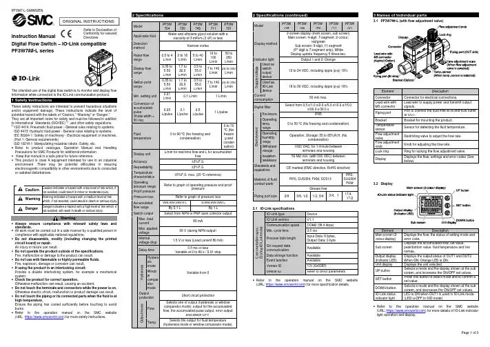
Instruction ManualDigital Flow Switch – IO-Link compatible PF3W7##-L seriesThe intended use of the digital flow switch is to monitor and display flow information while connected to the IO-Link communication protocol.These safety instructions are intended to prevent hazardous situations and/or equipment damage. These instructions indicate the level of potential hazard with the labels of “Caution,” “Warning” or “Danger.”They are all important notes for safety and must be followed in addition to International Standards (ISO/IEC) *1), and other safety regulations. *1)ISO 4414: Pneumatic fluid power - General rules relating to systems. ISO 4413: Hydraulic fluid power - General rules relating to systems.IEC 60204-1: Safety of machinery - Electrical equipment of machines. (Part 1: General requirements)ISO 10218-1: Manipulating industrial robots -Safety. etc.• Refer to product catalogue, Operation Manual and Handling Precautions for SMC Products for additional information. • Keep this manual in a safe place for future reference.• This product is class A equipment intended for use in an industrial environment. There may be potential difficulties in ensuring electromagnetic compatibility in other environments due to conducted or radiated disturbances.Caution Caution indicates a hazard with a low level of risk which, if not avoided, could result in minor or moderate injury.WarningWarning indicates a hazard with a medium level of riskwhich, if not avoided, could result in death or serious injury.DangerDanger indicates a hazard with a high level of risk which, ifnot avoided, will result in death or serious injury.Warning• Always ensure compliance with relevant safety laws and standards.• All work must be carried out in a safe manner by a qualified person in compliance with applicable national regulations.• Do not disassemble, modify (including changing the printed circuit board) or repair. An injury or failure can result.• Do not operate the product outside of the specifications. Fire, malfunction or damage to the product can result. • Do not use with flammable or highly permeable fluids. Fire, explosion, damage or corrosion can result. • If using the product in an interlocking circuit:Provide a double interlocking system, for example a mechanical system.• Check the product for correct operation.Otherwise malfunction can result, causing an accident.• Do not touch the terminals and connectors while the power is on. Otherwise electric shock, malfunction or product damage can result. • Do not touch the piping or its connected parts when the fluid is at high temperature.Ensure the piping has cooled sufficiently before touching to avoid burns.• Refer to the operation manual on the SMC website (URL: https:// ) for more safety instructions.2 Specifications2.1 IO-Link specificationsC o m m u n i c a t i o n s p e c . (D u r i n g I O -L i n k m o d e )IO-Link type Device IO-Link versionV1.1Communication speed COM2 (38.4 kbps) Min. cycle time 3.5 msProcess data length Input Data: 6 bytes, Output Data: 0 byte On request data communication Available Data storage function Available Event function Available Vendor ID 131 (0x0083)Device IDRefer to direct parameters• Refer to the operation manual on the SMC website (URL: https:// ) for more specification details.3.1 PF3W7##-L (with flow adjustment valve)ElementDescriptionConnector Connector for electrical connections.Lead wire with M8 connector Lead wire to supply power and transmit output signals.Piping port Port to connect the fluid inlet at IN and fluid outlet at OUT.Bracket Bracket for mounting the product. Temperature sensorSensor for detecting the fluid temperature. Flow adjustment valveRestricting valve to adjust the flow rate. Flow adjustment knob Knob for adjusting the flow rate.Lock ring Ring for locking the flow adjustment valve. DisplayDisplays the flow, settings and error codes (See below).Element DescriptionMain screen (2-colour display) Displays the flow, the status of setting mode and error code.Sub screen Displays the accumulated flow, set value, peak/bottom value, fluid temperature and line names.Output display (Indicator LED) Displays the output status of OUT1 and OUT2. When ON: Orange LED is ON. Unit display Displays the unit selected.UP button Selects a mode and the display shown at the sub screen, and increases the ON/OFF set values. SET button Press this button to select mode and to confirm a set value.DOWN button Selects a mode and the display shown at the sub screen, and decreases the ON/OFF set values. IO-Link status indicator lightLED is ON when OUT1 is used in IO-Link mode. (LED is OFF in SIO mode)• Refer to the operation manual on the SMC website (URL: https:// ) for more details of IO-Link indicator light operation and display.ORIGINAL INSTRUCTIONSRefer to Declaration of Conformity for relevant DirectivesModel PF3W704PF3W 720PF3W 740PF3W 711PF3W 721Applicable fluid Water and ethylene glycol solution with aviscosity of 3 mPa•s (3 cP) or lessDetection method Karman vortexRated flow range 0.5 to 4 L/min 2 to 16 L/min 5 to 40 L/min 10 to 100 L/min50 to 250 L/minDisplay flow range 0.35 to 5.50 L/min 1.7 to 22.0 L/min 3.5 to 55.0 L/min 7 to 140 L/min 20 to 350 L/min Switch point range 0.35 to 5.50 L/min 1.7 to 22.0 L/min3.5 to 55.0 L/min7 to 140 L/min 20 to 350 L/minMin. setting unit 0.01 L/min 0.1 L/min1 L/minConversion of accumulated pulse(Pulse width = 50 ms) 0.05 L/pulse0.1 L/pulse 0.5 L/pulse1 L/pulseFluid temperature 0 to 90 o C (No freezing andcondensation)0 to 70 oC (No freezin g and conden sation)Display unit L/min for real-time flow and L for accumulatedflowAccuracy ±3%F.S. Repeatability ±2%F.S.Temperature characteristics ±5%F.S. max. (25 o C reference)Operatingpressure range Refer to graph of operating pressure and proofpressureProof pressure Pressure loss Refer to graph of pressure lossAccumulated flow range 999,999,999.9 L9,999,999,999 LBy 0.1 LBy 1 LSwitch output Select from NPN or PNP open collector outputMax. load current 80 mAMax. applied voltage 30 V (during NPN output) Internal voltage drop 1.5 V or less (Load current 80 mA) Delay time 3.5 ms or lessVariable at 0 to 60 s / 0.01 stepH y s t e r e s i s Hystere sis mode Variable from 0Windo w compar ator mode Output protection Short circuit protectionO u t p u t m o d e FlowSelects one of output (hysteresis or window comparator mode), output for the accumulated flow, the accumulated pulse output, error outputand switch OFF. Temp. Selects the output for fluid temperature (hysteresis mode or window comparator mode).Model PF3W 704PF3W 720PF3W 740PF3W 711PF3W 721Display method 2-screen display (main screen, sub screen) Main screen: 4-digit, 7-segment, 2-colour;red/greenSub screen: 9-digit, 11-segment (5th digit is 7-segment only), White Display update frequency 5 times/sec.Indicator light Output 1 and 2: OrangeS u p p l y v o l t a g e Used as switch output device 12 to 24 VDC, including ripple (p-p) 10%Used as IO-Link device 18 to 30 VDC, including ripple (p-p) 10%Currentconsumption 50 mA max.Digital filter Select from 0.5 s/1.0 s/2.0 s/5.0 s/10.0 s/15.0s/20.0 s/30.0 sE n v i r o n m e n tEnclosure IP65Operating temp. range 0 to 50 oC (No freezing and condensation) Operating humidity range Operation, Storage: 35 to 85%R.H. (Nocondensation) Withstand voltage 1000 VAC, for 1 minute betweenterminals and housing Insulation resistance 50 M Ω min. (with 500 VDC) betweenterminals and housing Standards and regulations CE marked (EMC directive, RoHS directive)Material of fluidcontact parts PPS, SUS304, FKM, SCS13 PPS, SUS304FKM Grease free Piping port size 3/8 3/8, 1/2 1/2, 3/4 3/4、1 11/4、11/24.1 InstallationWarning•Do not install the product unless the safety instructions have been read and understood.•Use the product within the specified operating pressure andtemperature range.•Proof pressure could vary according to the fluid temperature. Check the characteristics data for operating pressure and proof pressure. 4.2 EnvironmentWarning•Do not use in an environment where corrosive gases, chemicals, salt water or steam are present.•Do not use in an explosive atmosphere.•Do not expose to direct sunlight. Use a suitable protective cover. •Do not install in a location subject to vibration or impact in excess of the product’s specifications.•Do not mount in a location exposed to radiant heat that would result in temperatures in excess of the product’s specifications.4.3 Mounting•Never mount the product in a location where it will be used as a support.•Mount the product so that the fluid flows in the direction indicated by the arrow on the side of the body.•Check the flow characteristics data for pressure loss and the straight inlet pipe length effect on accuracy, to determine inlet piping requirements.•Do not sharply reduce the piping size.•The monitor with integrated display can be rotated. It can be set at 90o intervals clock and anticlockwise, and also at 45o and 225o clockwise.Rotating the display with excessive force will damage the end stop.Bracket mounting (PF3W704 / 720 / 740)Mount the product (with bracket) using themounting screws supplied (M4 x 4 pcs).For models with flow adjustment valveattached, fix using 8 mounting screws.Bracket thickness is approx. 1.5 mm.Bracket mounting (PF3W711)Mount the product (with bracket) using themounting screws supplied(M5 x 4 pcs).Bracket thickness is approx. 2 mm.Direct mounting (PF3W704 / 720 / 740)Mount using self tapping screws(nominal size: 3.0 x 4 pcs).For models with flow adjustmentvalve attached, mount using 8 selftapping screws. Tightening torquemust be 0.5 to 0.7 Nm.Direct mounting (PF3W711)Mount using self tapping screws(nominal size: 4.0 x 4 pcs).Tightening torque must be 1.0 to 1.2Nm.Self tapping screws should not be re-used.Refer to the operation manual on the SMC website (URL: https://) for mounting hole details and outline dimensions. 4.4 PipingCaution•Before connecting piping make sure to clean up chips, cutting oil, dustetc.•When installing piping or fittings, ensure sealant material does notenter inside the port.•Ensure there is no leakage after piping.•When connecting piping to the product, a spanner should be used onthe metal piping attachment only.Using a spanner on other parts may damage the product.In particular, do not let the spanner come into contact with the M8connector. The connector can be easily damaged.Width across flats of attachment3/8 20.9 mm1/2 23.9 mm3/4 29.9 mm1 41 mmAfter hand tightening, apply a spanner of the correct size to thespanner flats on the product, and tighten it for 2 to 3 rotations, to thetightening torque shown in the table below.Nominal thread size Tightening torqueRc(NPT)3/8 15 to 20 NmRc(NPT)1/2 20 to 25 NmRc(NPT)3/4 28 to 30 NmRc(NPT)1 36 to 38 NmRc(NPT)1 1/4 40 to 42 NmRc(NPT)1 1/2 48 to 50 NmIf the tightening torque is exceeded, the product can be damaged. Ifthe correct tightening torque is not applied, the fittings may becomeloose.4.5 WiringCaution•Do not perform wiring while the power is on.•Confirm proper insulation of wiring.•Do not route wires and cables together with power or high voltagecables.Otherwise the product can malfunction due to interference of noise andsurge voltage from power and high voltage cables to the signal line.Route the wires (piping) of the product separately from power or highvoltage cables.•Keep wiring as short as possible to prevent interference fromelectromagnetic noise and surge voltage.Do not use a cable longer than 20 m.•Ensure that the FG terminal is connected to ground when using acommercially available switch-mode power supply.When used as switch output deviceNo. NameWirecolourFunction1 DC(+) Brown 12 to 24 VDC2N.C./OUT2WhiteNot connected /Switch output 2 (SIO)3 DC(-) Blue 0 V4 OUT1 Black Switch output 1When used as IO-Link deviceNo. NameWirecolourFunction1 L+ Brown 18 to 30 VDC2N.C./OUT2WhiteNot connected /Switch output 2 (SIO)3 L-Blue 0 V4 C/Q BlackIO-Link data /Switch output 1 (SIO)∗: Wire colours are for lead wire included with the PF3W7 series.5.1 Measurement modeThe mode in which the flow is detected and displayed, and the switchfunction is operating.This is the basic operating mode; other modes should be selected for set-point and other function setting changes.5.2 Switch operationWhen the flow exceeds the set value, the switch will be turned ON.When the flow falls below the set value by the amount of hysteresis ormore, the switch will be turned OFF.If the operation shown below is acceptable, keep this setting.5.3 3-step setting mode1. Press the SET button in measurement mode to display set values.(The item to be changed is displayed on the sub display)Set value on the right side of the sub screen flashes.2. Press the UP or DOWN button to change the set value.The UP button is to increase and the DOWN button is to decrease.•Press the UP button once to increase by one digit, or press and holdto continuously increase.•Press the DOWN button once to decrease by one digit, or press andhold to continuously decrease.3. Press the SET button to finish the setting.•For setting of hysteresis, perform the settings referring to [F 1] Settingof OUT1.•Note that the set value and hysteresis are limited by each other.•For more detailed settings, set each function in Function selectionmode.6.1 Function selection modeIn measurement mode, press the SET button for 3 to 5 seconds to display[F ] on the main screen.Select to display the function to be change [F ].Press and hold the SET button for 2 seconds or longer in functionselection mode to return to measurement mode.The function number is increased and decreased by the UP and DOWNbuttons. Display the required function number and press the SET button.6.2 Sub screen displayIn measurement mode, the sub screen display can be temporarilychanged by pressing the UP or DOWN buttons.After 30 seconds, it will automatically reset to the display selected in[F10].Example shown is for the 16 L/min type.6.3 Default settingsItem Default setting[F 0][Unit] Display units [ L] L/min, o C[N orP] Switch outputNPN/PNP[PnP] PNP output[F 1][oUt1] Output mode(OUT1)[HYS] Hysteresis mode[1ot] Switch operation(OUT1)[1_P] Normal output[P_1] Set value (OUT1) 50% of maximum rated flow[H_1] Hysteresis (OUT1) 5% of maximum rated flow[dtH1] Delay time at ON [0.00] 0.00 s[dtL1] Delay time at OFF [0.00] 0.00 s[CoL] Display colour(OUT1)[1SoG] ON: GreenOFF: Red (OUT1)[F 2]Notemp.sensor[oUt2] Output mode(OUT2)[HYS] Hysteresis mode[2ot] Switch operation(OUT2)[2_P] Normal output[P_2] Set value (OUT2) 50% of maximum rated flow[H_2] Hysteresis (OUT2) 5% of maximum rated flow[dtH2] Delay time at ON [0.00] 0.00 s[dtL2] Delay time at OFF [0.00] 0.00 s[CoL] Display colour(OUT2)[1SoG] ON: GreenOFF: Red (OUT2)[F 2]Withtemp.sensor[oUt2] Output mode(OUT2)[tHYS] TemperatureHysteresis[2ot] Switch operation(OUT2)[2_n] Reverse output[tn_2] Set value (OUT2) 50% of maximum rated temp.[ t H_2] Hysteresis (OUT2) 0% of maximum rated temp.[dtH2] Delay time at ON [0.00] 0.00 s[dtL2] Delay time at OFF [0.00] 0.00 s[CoL] Display colour(OUT2)[1SoG] ON: GreenOFF: Red (OUT2)ItemDefault setting[F 3][ FiL] Digital filter setting[ 1.0] 1.0 s[F10][ SUb] Sub screendisplay setting[ dEF] Standard (OUT1 setvalue displayed)∗: When a temperature sensor is not connected. [ dEF] Standard (fluidtemp. displayed)∗: When a temperature sensor is connected. [F30] [ SAvE] Accumulated flowvalue storage[ oFF] Not saved [F80] [ diSP] Display OFFmode[ on] Normal display [F81] [ Pin] Security codesetting[ oFF] OFF [F90] [ ALL] Setting of allfunctions[ oFF] OFF[F98] [ tESt] OUT1 output testmode[ n] Normal output [F99] [ ini] Reset to thedefault settings[ oFF]OFF• Snap shot function • Key-lock functionRefer to the operation manual on the SMC website (URL: https:// ) for setting these functions. 9.1 General MaintenanceCaution• Not following proper maintenance procedures could cause the product to malfunction and lead to equipment damage.• If handled improperly, compressed air can be dangerous.• Maintenance of pneumatic systems should be performed only by qualified personnel.• Before performing maintenance, turn off the power supply and be sure to cut off the supply pressure. Confirm that the air is released to atmosphere.• After installation and maintenance, apply operating pressure and power to the equipment and perform appropriate functional and leakage tests to make sure the equipment is installed correctly.• If any electrical connections are disturbed during maintenance, ensure they are reconnected correctly and safety checks are carried out as required to ensure continued compliance with applicable national regulations.• Do not make any modification to the product.• Do not disassemble the product, unless required by installation or maintenance instructions.• How to reset the product after a power cut or when the power has been unexpectedly removedThe settings of the product are retained from before the power cut or de-energizing.The output condition also recovers to that before the power cut or de-energizing, but may change depending on the operating environment. Therefore, check the safety of the whole system before operating the product.10.1 Error indicationIf the error cannot be reset after the above measures are taken, or errors other than the above are displayed, please contact SMC.Refer to the operation manual on the SMC website (URL: https:// ) for more detailed information about troubleshooting.11 How to OrderRefer to drawings/catalogue for ‘How to Order’.12 Outline Dimensions (mm)Refer to drawings/catalogue for outline dimensions.13 Limitations of Use8.1 Limited warranty and Disclaimer/Compliance Requirements Refer to Handling Precautions for SMC Products.14 ContactsRefer to Declaration of Conformity and URL: https:// for contacts.URL : https:// (Global) https:// (Europe) 'SMC Corporation, Akihabara UDX15F, 4-14-1, Sotokanda, Chiyoda-ku, Tokyo 101 0021Specifications are subject to change without prior notice from the manufacturer. © 2019 SMC Corporation All Rights Reserved. Template DKP50047-F-085H。


产品规格书品名:PM2.5激光传感器型号:LD13(C版)广州勒夫迈智能科技有限公司研发中心目录六、输出结果 (3)七、可靠性测试 (3)八、产品安装尺寸图 (7)安装注意事项 (8)附录一:通讯协议 (9)协议A(默认):.....................................................................................................................9-15协议B:...................................................................................................................................11-17六、输出结果主要输出为单位体积内各浓度颗粒物质量以及个数,其中颗粒物个数的单位体积为0.1升,质量浓度单位为:微克/立方米。
输出分为主动输出和被动输出两种状态。
传感器上电后默认状态为主动输出,即传感器主动向主机发送串行数据,时间间隔为1秒。
电路设计应注意:1.LD13工作电压为5V,数据通讯和控制管脚均需要3.3V作为高电平。
(主板MCU为5V供电,需要在通讯线(RXD、TXD)和控制线(SET、RESET)上应当加入电平转换芯片或电路)2.SET和RESET内部有上拉电阻,如果不使用,则应悬空。
3.PIN4为程序内部调试用,应用电路中应使其悬空。
典型输出特性纵坐标单位:μg/m³(PM2.5质量浓度标准值),横坐标单位:次图1-1传感器常温一致性(25℃)图1-2传感器高温一致性(45℃)图1-3传感器低温一致性(-5℃)图1-4传感器长时间运行一致性(30天)一致性与温度对应关系横坐标单位:℃.图1-5一致性最大绝对值偏差随温度变化关系七、可靠性测试序号项目测试方法1长时间运行1、10㎡封闭实验室,温度湿度30~70%,颗粒物发生器送烟,空气净化器调节。

Speed Sensors Product Range GuideWith more than 50,000 products ranging from snap-action, limit, toggle, and pressure switches to position, speed, pressure, and airflow sensors, Honeywell has one of the broadest sensing and switching portfolios.Honeywell sensor, switch, and control components are tailored to exact specifications for stronger performance, longer productivity, and increased safety. Enhanced accuracy and durability are built into every part, improving output and endurance. For our customers, this can reduce expenditures and operational costs. Our global footprint and channels help to competitively price such components for your chosen application and provide immediate technical support.While Honeywell’s switch and sensor solutions are suitable for a wide array of basic and complex applications, our custom-engineered solutions offer enhanced precision, repeatability, and ruggedness. We offer domain knowledge and technology resources, along with a close working relationship, to develop and deliver cost-effective, individually tailored solutions. Whether clean-slate development or simple modifications to an existing design are needed, our expertly engineered solutions help to meet the most stringent requirements with world-class product designs, technology integration, and customer-specific manufacturing.Global service, sourcing, and manufacturing. Industry-leading engineers. Value-added assemblies and solutions. A one-stop, full-service, globally competitive supplier.For innovation that’s well apart, there’s only HoneywellTable of ContentsMagnetoresistive Sensor ICs . . . . . . . . . . . . . . . . . . . . . . . . . . . . . . . . . . . . . . .3Hall-effect Digital Sensor ICs . . . . . . . . . . . . . . . . . . . . . . . . . . . . . . . . . . . .4-5Hall-effect Digital and Linear Sensor ICs . . . . . . . . . . . . . . . . . . . . . . . . . . .6Value Added Magnetic Sensors . . . . . . . . . . . . . . . . . . . . . . . . . . . . . . . . . .7-8Active Speed Sensors . . . . . . . . . . . . . . . . . . . . . . . . . . . . . . . . . . . . . . . . . .9-10Passive Speed Sensors . . . . . . . . . . . . . . . . . . . . . . . . . . . . . . . . . . . . . . . . . . . .113NanopowerSeriesStandardPowerSeries2SS52MSeriesVF401APS00BDescription omnipolar MRsensor IComnipolar MRsensor IComnipolar MRdigital sensor IC2-wire MRfine pitch ringmagnet sensor IChigh resolutionmagneticdisplacementMagnetic Sensors |Magnetoresistive Sensor ICs1Dimensions:• SOT-23: 2,8 mm x 2,9 mm [0.11 in x 0.11 in]• Flat TO-92-style: 3,0 mm x 4,0 mm [0.12 in x 0.16 in] (not including leads)• VF-401 flat TO-92-style: 3,0 mm x 4,06 mm [0.12 in x 0.16 in] (not including leads)• SOT-89B: 4,2 mm x 4,5 mm [0.16 in x 0.18 in]• U-Pack: 4,5 mm x 4,5 mm [0.18 in x 0.18 in] (not including leads)• SOIC-8: 4,9 mm x 6,0 mm [0.19 in x 0.24 in]SL353SS30AT,SS40A,SS50ATSS311PT,SS411PSS340RT,SS440RSeriesDescriptionmicropower omnipolarHall-effect digitalsensor IClow-cost bipolarHall-effect digitalsensor IClow-cost bipolarHall-effect digital sensorIC with built-in pull-uplow-cost unipolarHall-effect digitalsensor ICFeaturescombined with very lowaverage current reducespower consumptionspeed capability, reversepolarity protectionlow voltage, enhancedsensitivityNorth pole (SS340RT)or South pole (SS440R),multiple magneticsensitivities (high,medium, and low) Magnetic Sensors |Hall-effect Digital Sensor ICs1Dimensions:• SOT-23: 2,8 mm x 2,9 mm [0.11 in x 0.11 in]• Flat TO-92-style: 3,0 mm x 4,0 mm [0.12 in x 0.16 in] (not including leads)• SOT-89B: 4,2 mm x 4,5 mm [0.16 in x 0.18 in]5SS345PT, SS445PSS351AT, SS451A, SS551ATSS360NT , SS360ST , SS360ST-10K, SS460S, SS460S-T2 VF360NT , VF360ST , VF460SSS360PT, SS460P, SS460P-T2unipolar Hall-effect digital sensor IC with built-in pull-up resistor low-cost omnipolarHall-effect digital sensor IC high sensitivity, latching Hall-effect digital sensor IC high sensitivity, latching Hall-effect digital sensor IC high sensitivity latching digital Hall-effect sensor IC with built-in pull-up resistor pole (SS345PT) or a South pole (SS445P)protection, typical operating point of 85 G at 25°C [77°F]no chopper stabilizationstandard for potential use in automotive applications, fastest response time in its class class, no chopper stabilization, operates from only 30 Gausstypical, at 25°C [77°F]Magnetic Sensors |Hall-effect Digital and Linear Sensor ICsDigitalVF526DTLinearSS490 SeriesSS39ET, SS49E, SS49E-F, SS49E-L, SS49E-T2, SS49E-T3, SS59ET1Dimensions:• 4-Pin SIP: 3,6 mm x 5,1 mm [0.14 in x 0.20 in]• SOT-89B: 4,2 mm x 4,5 mm [0.16 in x 0.18 in]• Flat TO-92-style:3,0 mm x 4,0 mm [0.12 in x 0.16 in] (not including leads)7Series103SR (digital)103SR (linear)Magnetic Sensors | Value AddedSeries SR16/SR17SR3SR4Description low-cost Hall-effect vane sensor Hall-effect digital position sensor magnetoresistive digitalMagnetic Sensors |Value Added9Series SNG-Q SNDH-T SNDH-HDescription quadrature speed and direction quadrature speed and direction single Hall-effect speed sensorFeaturesplatform-based approachenables cost-competitivenessand mechanical and electricalconfigurability; designed forpotential applications whereenhanced accuracy is required todetect small target featuresoffset self calibration, short circuitand reverse voltage protection,low jitter output, near zero speedavailable, zero speed sensingversions available, range of con-nector options Speed Sensors |ActiveSpeed Sensors |ActiveSeries584XXFeaturesproduces constant amplitude output signals suitable for direct use in many digital andlogic control applications, internal digital signal conditioningSeriesLCZZH10Featuresomni-directional sensor to target, low power consumption, zero speed, digital outputomni-directional sensor to target, low powerconsumption, zero speed, digital output11SeriesVRS General PurposeVRS Hazardous LocationVRS High OutputDescription/potential applicationsused where medium to high speeds or in electrically noisy environments with relatively small air gaps existused where explosion-proof or intrinsically safe sensors are requiredused where higher output voltages are needed, perform best at low to mediumspeeds with medium to high impedance loads (sealed front-end versions for use where the sensor is exposed to fluids, lubricants or adverseSeriesVRS High ResolutionVRS High TemperatureVRS Power OutputDescription/potential applicationsused where precise timing pulse is required, and/or fine pitch gears are usedused where the sensor is exposed to temperatures up to 260ºC [450ºF] (sealed front-end versions for use where the sensor is exposed to fluids, lubricants or adverse used where driving lowresistance loads at large air gaps is required, and larger actuators are usedSpeed Sensors |PassiveWarranty/RemedyHoneywell warrants goods of its manufacture as being free of defective materials and faulty workmanship during the applicable warranty period . Honeywell’s standard product warranty applies unless agreed to otherwise by Honeywell in writing; please refer to your order acknowledgement or consult your local sales office for specific warranty details . If warranted goods are returned to Honeywell during the period of coverage, Honeywell will repair or replace, at its option, without charge those items that Honeywell, in its sole discretion, finds defective . The foregoing is buyer’s sole remedy and is in lieu of all other warranties, expressed or implied, including those of merchantability and fitness for a particular purpose. In no event shall Honeywell be liable for consequential, special, or indirect damages.While Honeywell may provide application assistance personally, through our literature and the Honeywell web site, it is buyer’s sole responsibility to determine the suitability of the product in the application .Specifications may change without notice . The information we supply is believed to be accurate and reliable as of this writing . However, Honeywell assumes no responsibility for its use .005911-11-EN IL50 GLO Printed in USA May 2017© 2017 Honeywell International Inc . All rights reserved .Find out moreTo learn more about Honeywell’s sens-ing and switching products, call +1-815-235-6847, email inquiries to *********************, or visit Honeywell Sensing and Internet of Things 9680 Old Bailes Road Fort Mill, SC 29707 honeywell .com。

Vibration SensorsD7SThe World's Smallest Class Size,High-precision Seismic Sensor.IoT Friendly.The SI value (or spectral intensity) is equivalent to the magnitude of the destructive energy imposed by seismic motion on structures.The SI value, which is the average value of the integrated velocity response spectrum, is an index that expresses the destructive force of seismic motion and is highly correlated with the damage to structures.SI =Sv (T,h)dT∫1 2.5SI value What Is an SI Value?Vibration Sensors D7S9.8mmD7S10.9mmCompact & High-precision Seismic Sensors- Reducing Secondary Disasters from Earthquakes3EarthquakeEarthquake ends.Emergency ActionsWith their high detection accuracy, these Sensors help with measures to prevent secondary damage after earthquakes in a variety of settings.PreventingSecondary DamageShutting Off and Stopping Hazardous Devices - Semiconductors - Chemical plants - Distribution panels456D 7SHelps Prevent Fire and Other Second-ary Disasters after an Earthquake.The World’s Smallest Class Size Seismic Sensor.•Using the SI value, which has a high correlation with the seismic intensity scale that indicates the magnitude of an earthquake, provides higher-precision judgment of seismic intensity scales.•The 3-axis acceleration Sensor and OMRON’s unique SI value calculation algorithm achieve surface-mountable compact modules and low power consumption.•Higher degree of freedom for incorporation into devices and prolonged operation on battery power.•Shutoff output terminal (INT1) operates equivalent to a conventional mechanical vibration sensor and ensures compatibility with mechanical vibration sensors.•I 2C interface is able to obtain earthquake-related information from the Sensor with communications from external devices.Ordering InformationCharacteristics/PerformanceRoHS CompliantRefer to theSafety Precautions on page 9.TypeAppearancePower supply voltageModelSurface-mounting Vibration Sensor2.1 to 5.5 V D7S-A0001ItemModelD7S-A0001Power Supply Voltage 2.1 to 5.5 VCurrent consumption During standby: 90 μA or less Processing (average): 300 μA or less Operating Temperature −30 to 70°C (with no condensation or icing)Storage Temperature −40 to 80°C (with no condensation or icing)Ambient Humidity 25% to 95% (with no condensation or icing)Storage Humidity25% to 95% (with no condensation or icing)Acceleration Detection Range −2,000 to 2,000 galShutoff Output (INT1)Output at seismic intensity level 5 or higher.Communications Interface I 2C Dimensions 10.9 × 9.8 mmInstallation angle±5°7D7SVibration SensorD 7SConnections●Terminal Arrangement●Block Diagram●Circuit DiagramsNo.Signal FunctionDirection Description1VCC Power supply voltage ---2INT1Shutoff outputOUTAn open-drain output.Goes active (ON) when the shutoff judgment condition and collapse detection condition are met.3INT2Processing notification output OUT An open-drain output.Goes active (ON) during earthquake calculations, offset acquisition, and self-diagnostic processing.4SCL I 2C clock IN Pull up the voltage to VCC even when you do not use I 2C.5SDA I 2C dataIN/OUTPull up the voltage to VCC even when you do not use I 2C.6GND Power supply ground ---7SETTING Initial setting input INChanges the Sensor to Initial Installation Mode for an input from an external device.Normal Mode: High Initial Installation Mode: Low8NC Not connected ---Completely floating and cannot be connected to another line.9VCC Power supply voltage ---10GNDPower supply ground---8D7SVibration SensorD 7SOperation ChartDimensions (Unit: mm)D7S-A0001Recommended Mounting Pattern(TOP VIEW)Recommended Mounting ConditionsPeak mounting temperature: 245°C min. (260°C max.)Reflow time: 64 to 80 s (220°C)Reflow repetitions: Up to 29D7SVibration SensorD 7SSafety PrecautionsThis Sensor is a precision device. Do not drop it or subject it to excessive shock or force. Doing so could break it or change its characteristics. Do not use the Sensor if it has been dropped.●Operating Environment•Do not use the Sensor in locations with volatile, flammable, or corrosive gas (organic solvent vapor, sulfite gas, chlorine, sul-fide gas, ammonia gas, etc.) or other toxic gases. They may cause the Sensor to break down.•Do not use the Sensor in locations subject to fresh water, salt water, water drops, or splattering oil.•Do not use the Sensor in an environment where condensation or icing may occur. Moisture freezing on the Sensor may cause output to fluctuate or may cause the Sensor to break down.•Do not use the Sensor in locations subject to direct sunlight. Doing so may cause the Sensor to break down.•Do not use the Sensor in locations subject to direct radiant heat from heating equipment. Doing so may cause the Sensor to break down.•Do not use the Sensor in locations with severe temperature changes. Doing so may cause the Sensor to break down.•Do not use the Sensor in environments with excess mechani-cal stress. Doing so may cause the Sensor to malfunction or break down.•Do not use the Sensor in locations with large vibration or shock. These may cause the Sensor to break down.•Do not use the Sensor in locations with strong electrical or magnetic fields. These may cause the Sensor to break down.●Countermeasures against Noise•The Sensor does not contain any protective circuits. Never allow the electrical load to exceed the absolute maximum rat-ings. Such loads may damage the circuits. If required, install protective circuits so that absolute maximum ratings are not exceeded.•Allow as much space as possible between the Sensor and devices that generate surges or high frequencies (such as high-frequency welders and high-frequency sewingmachines). Attach a surge protector or noise filter on nearby noise-generating devices (in particular, motors, transformers, solenoids, magnetic coils, or other devices that have an induc-tance component).•Wire the Sensor away from high-voltage and large-current power lines in order to prevent inductance noise. It is also helpful to separate conduits and ducts and to use shielded cables.•When using a switching regulator, power supply switching noise may cause malfunctions, so check this before use.●Handling•Static electricity can destroy the Sensor. Take countermea-sures including grounded work benches, floors, and other charged objects and workers.•Do not handle the Sensor in locations with excessive vapor, dust, dirt, etc.•Do not hold the Sensor with pliers, tweezers, or similar tools, and do not subject components to damage or excessive shock due to inadequate adjustment of the mounter.•When placing components near the edge of the PCB or near a connector, make sure that stress is not applied to the Sensor when the device is assembled or when the connector is con-nected or disconnected.•Do not apply any external force to components after soldering until everything has cooled off and do not allow mechanical stress due to PCB warping or other factors.•Under some usage conditions, ultrasound may cause the Sen-sor to resonate and be destroyed. OMRON cannot specify the detailed conditions under which the Sensor will be used, so we assume no responsibility if the Sensor is used in environments where ultrasound is used. If the Sensor must be used in an environment with ultrasound, check its performance in the actual environment beforehand.•Stress due to plastic hardening may change Sensor character-istics. Do not mold seal the Sensor after mounting.•When applying a moisture preventing coating or other coating after mounting the Sensor, select a coating with minimal stress and check operation carefully.•Do not attempt to disassemble or modify the Sensor.•Do not use the Sensor in safety devices or for applications in which Sensor operation would directly affect human life.•Carefully read the precaution in the Instruction Manual before using the Sensor.•In addition, if you use the Sensor under conditions other than those in these specifications, check Sensor operation under those conditions beforehand.●Shipping and Storage•Do not store the Sensor in locations with harmful corrosive gas (organic solvent vapor, sulfite gas, sulfide gas, etc.)•The Sensor is not drip proof, so do not store it anywhere that water might get on it.•Store the Sensor within appropriate temperature and humidity ranges.*Before storing the Sensor in an environment other than the environment recommended by OMRON, evaluate the results in the actual storage environment and judge whether or not storage there is appropriate.•Do not store the Sensor in locations with excessive vapor, dust, dirt, etc.CautionPrecautions for Correct UseMEMO10• Application examples provided in this document are for reference only. In actual applications, confirm equipment functions and safety before using the product.• Consult your OMRON representative before using the product under conditions which are not described in the manual or applying the product to nuclear control systems, railroad systems, aviation systems, vehicles, combustion systems, medical equipment, amusement machines, safety equipment, and other systems or equipment that may have a serious influence on lives and property if used improperly. Make sure that the ratings and performance characteristics of the product provide a margin of safety for the system or equipment, and be sure to provide the system or equipment with double safety mechanisms.Note: Do not use this document to operate the Unit. OMRON CorporationElectronic and Mechanical Components Company Contact: /ecb Cat. No. A252-E1-031216(0316)(O)。

USER MANUALFORBATH SENSING MODULE V7 Doc. Ref. 4601598 ver. 1.16Last Modified: 5 March 2012Copyright Parker Hannifin Corporation 2012. Confidential and Proprietary. All Rights Reserved.Copying of this document and distributing it to others, or the use or communication of the contents thereof, is forbidden without prior written authorization. The copyright notice hereon shall not constitute or imply publication.This manual provides basic details of the Bath Sensing Module V7 and includes a fault finding guidelines in case of problems.Contents:Page subject3 Installation and Warning notices4…6Specifications7 Dimensions8…9Connection overview10 Bath Sensing Module wiring proposal11…12 Fuses13…14Indicators15 Power Up Sequence16…19 Error handling20 DeclarationsTo access and check for the latest version then go to: -Installation Manual -http://literature/Pneumatics Division Europe/PDE-Documents/BSM-V7_Installation_Manual-UK_4601598.pdfQuick reference guide - http://literature/Pneumatics DivisionEurope/PDE-Documents/BSM-V7_Quick_Ref_Installation_Manual-UK_4601594.pdfInstallation and Warning NoticesThis device is intended for industrial use only.WarningWarningSPECIFICATIONS(all values measured at room temperature unless otherwise noted)Power supply(pin 16 vs. pin 15) 24V +/-10%Current consumption(pin 16 vs. pin 15) max. 65mA(excluding PNP signals ) Inrush current @ 23 ºC(pin 16 vs. pin 15) max. 300mAInternal thermal 24V fuse rating0,75 / 1,50 A @ 23 ºC0,41 / 0,82 A @ 70 ºC(hold current / trip current)Optional Input(pin 11 vs. pin 15) min. 22 V / max. 28 V Current consumption @24V(pin 11 vs. pin 15) max. 6mAChisel in bath, PNP Output (pin 14 vs. pin 15) PNP, 24VPNP current sourcing capabilities(pin 14 vs. pin 15) max. 100mA 1) 2)Chisel in bath, NPN Output(pin 10) NPN, max. 30VNPN current sinking capabilities(pin 10) max. 100mA 3) (ifmoreoutputcurrentisneeded,*******************************)SPECIFICATIONS (continued)Status Signal, PNP Output(pin 13 vs. pin 15) PNP, 24VPNP current sourcing capabilities(pin 13 vs. pin 15) max. 100mA 1) 2)Status Signal, NPN Output(pin 9) NPN, max. 30VNPN current sinking capabilities(pin 9) max. 100mA 3) (ifmoreoutputcurrentisneeded,*******************************)Maximum chisel current(pin2/4 vs. pin6/8) 25mAMaximum chisel withstand-voltage(pin2/4 vs. pin6/8) >750VMaximum sensing range(pin2/4 vs. pin6/8) >8,5V 4) Temperature range0 … 70 ºCMinimum isolation voltage between>3,0kVDC continuous. cathode referenced and 0V (PLC) referencedsides of the PCBMinimum physical separation on PCB6,3 mmbetween cathode- and 0V-GND planes.Dimensions 12 x 10 x 2,4 cmSPECIFICATIONS (continued)Notes:1) Although the PNP output driver is self-limiting in case of a short circuit, it is recommended to limit the short circuit duration to a minimum. During a short circuit the PNP output led will be OFF. Initial short circuit peak current is 0,9A+. Theoretically this peak, in combination with high ambient temperature, could also trip the thermal main fuse inside the module. Solving the short circuit and turning the module off for 20 seconds will get it working again.2) In case of applying 24V to the Chisel in bath and/or Status signal outputs, in combination with reversed power supply wiring, the applied reverse current should not exceed 200mA. Otherwise the output driver might be damaged.3) Although the NPN output driver disables itself in case of a short circuit, it is recommended to limit the short circuit duration to a minimum amount of time. During a short circuit the NPN output led will remain ON because the led is connected to the PNP driver only. The NPN driver will enable itself again during the next cycle providing that the short circuit is removed. Initial short circuit peak current is neglectable.4) Sensing range is equal to the maximum bath voltage (including wiring and fuse losses!) the Bath Sensing Module is able to respond to, when supplied with 24,0V. When the module is supplied with the specified minimum voltage (24-10% = 21,6V), the sensing range might decrease with 0,1…0,25 volt.DIMENSIONSCONNECTION OVERVIEWPIN 01 NOT CONNECTED, PLEASE DON’T USE.PIN 02 C HISEL (SPARE CONNECTION)PIN 03 NOT CONNECTED, PLEASE DON’T USE.PIN 04 CHISEL (PIN 02 and PIN 04 are internally connected)PIN 05 NOT CONNECTED, PLEASE DON’T USE.PIN 06 CATHODEPIN 07 NOT CONNECTED, PLEASE DON’T USE.PIN 08 CATHODE (PIN 06 and PIN 08 are internally connected)PIN 09 STATUS OUTPUT NPNPIN 10 CHISEL IN BATH OUTPUT NPNPIN 11 OPTIONAL INPUT (24V)PIN 12 DATA-LOG-OUT *)PIN 13 STATUS OUTPUT PNPPIN 14 CHISEL IN BATH OUTPUT PNPPIN 15 0V POWER SUPPLYPIN 16 +24V POWER SUPPLYNotes:- Do not use the spare PIN 02 (or PIN 04) to loop a chisel wire to next module!Every chisel wire should have its own Bath Sensing module.- One of both cathode pins (PIN 06 or PIN 08) can be used to loop the cathodewire to the next module(s). Looped cathode wires should be from one pot only.Never connect cathode wires from different pots together.- PIN 12 (data-log-output) is only to be used by authorized employees. Data-log PIN 12 should be connected to measurement systems with proper galvanic isolation. Multi-meters and laptops (without charger!) are preferred!CONNECTION OVERVIEW (continued)BATH SENSING MODULE WIRING PROPOSALFUSESGeneral infoMost smelters use one chisel fuse per breaker and one common cathode fuse per pot to fuse the Bath Sensing modules. These fuses can have a huge impact on Bath Sensing performance. In terms of Bath Sensing performance, the main fuse characteristic that is important to observe is the ohmic resistance of the fuse.Unfortunately most fuse manufacturers don’t specify ohmic resistance in their datasheets. However, a reasonable indication of fuse resistance can be calculated with data that is usually provided in datasheets: voltage drop is namely the product of current through the fuse, times the fuse resistance. Thus the fuse resistance can be calculated with:[ fuse resistance = max. voltage drop / nominal current ]Fuse selectionTo reach optimum Bath Sensing performance aim to select fuses that have a resistance between 0 and 15 Ohms.Sometimes it might be required to choose a fuse with a higher rated current than normally would have been chosen solely based on the chisel current ( max 25mA / nominal 12mA ) ExampleThe following examples are referring to the datasheet of SIBA fuses on the next page.32mA fuse => resistance = 4500mV / 0,032mA = 141 Ω100mA fuse => resistance = 1500mV / 0,100mA = 15 Ω125mA fuse => resistance = 17000mV / 0,125mA = 136 Ω1A fuse => resistance = 1200mV / 1A = 1,2 Ω2A fuse => resistance = 800mV / 2A = 0,4 ΩExclusively seen from Bath Sensing performance viewpoint, the 1A and 2A fuses would be the best fuses to select.FUSES (continued)Disclaimer:This chapter FUSES only gives an overview of the process for meeting the essential fuse resistance requirements for optimal Bath Sensing performance. The customer always remains ultimately responsible for the safety and compliance of the whole system to regulations applying to pot rooms.INDICATORSINDICATORS (continued)RED = STATUS signalThe red STATUS led has two functions:- During normal use, the red led will flash every few seconds to indicate a certain firmware calculation has ended successfully.- When an internal error is discovered by the firmware, the red STATUS led will light up continuously.If the chisel [PIN2/4] and cathode [PIN6/8] pins are shorted deliberately, i.e. for testing purposes, the red led might come up (in combination with yellow CHISEL IN BATH led). As long as both led’s turn off again after the short circuit is removed, there is nothing wrong with the module.YELLOW = Chisel in Bath signalYellow led will light up when the module senses the chisel is in contact with the bath.GREEN = Power supply indicator- When the green led is continuously ON, all (internal) power supplies are working within specifications.- If the chisel [PIN2/4] and cathode [PIN6/8] pins are shorted deliberately, i.e. for testing purposes, the green led might turn off (in combination with CHISEL IN BATH and/or S TATUS led’s both on). As long as the green led turns on again after the short circuit is removed, there is nothing wrong with the module.ORANGE = Optional InputOrange led will light up when the optional input [PIN11] is enabled. Please note that this function is not mandatory for proper function. Do not connect this input without consulting Parker.NOTE:Two pot meters are visible between the yellow and green led’s.Please do not change the settings of these pot meters without consulting PARKER.POWER UP SEQUENCEDuring the first 60 seconds after powering up the Bath Sensing module, this Power Up Sequence analyzes the chisel voltage, temperature influences etc. to improve accuracy especially during pot-start up.Although the firmware is able to filter out one crust breaking cycle (including physical contact between chisel en bath) during this Power Up Sequence, it is recommended to prevent bath contacts for the first 60 seconds after powering on the module, i.e. by temporarily opening the chisel fuse. In case more Bath Sensing modules are powered up at once, opening the cathode fuse would be the most convenient way to prevent disturbing the Power Up Sequence.Please note that the Bath Sensing Modules will NOT respond to any bath contactsduring the Power Up Sequence at all!To notify the Power Up Sequence is running, the red and green led’s are used as following: •Green led flashes every other second. (1 seconds off / 1 second on) •Red led flashes every 6 seconds for 10msec. (5,99 seconds off / 10msec on)10 times in total during “power up” sequence.When the green led is continuously on, the Power Up Sequence is finished and normal Bath Sensing function will start.ERROR HANDLINGGREEN led is OFF (or blinking irregularly):- Check the +24V power supply. [PIN15 vs PIN16]- If 24V is available and stable, open the chisel fuse and then remove the +24V supply.[PIN16] - Wait 1 minute before reconnecting the +24V supply [PIN16].- If the green led starts blinking with one second interval (indicating the Power Up Sequence is running) wait until the green led is on continuously before closing the chisel fuse.(Please see the chapter “Power Up” Sequence”)If the green led refuses to light up whilst the 24V power supply is available and the chisel fuse is opened, disconnect the wiring and exchange the module. Contact PARKER.YELLLOW CHISSEL IN BATH led stays OFF:Make sure the chisel is physically capable of reaching the bath by performing a manual stroke. Bath liquid should be visible on the chisel upon retraction. Bath Sensing ca n’t perform its function when bath level is beyond the chisel’s mechanical reach!If the bath is within the mechanical reach of the chisel, please reset the module by following the procedure below.RESET PROCEDURE- Open the chisel fuse and turn the module off by disconnecting the +24 Volt [PIN16]- Wait 1 minute.- Turn the module ON again by reconnecting [PIN16]. (with chisel fuse still opened!)- If the green led starts blinking with one second interval (indicating the Power Up Sequence is running) wait until the green led is on continuously.END RESET PROCEDUREERROR HANDLING (continued)After the RESET the red led should flash every 2 or 3 seconds.Use a multi-meter to measure chisel/cathode voltage directly on the Bath Sensing module between [PIN2/4 and PIN6/8] with the chisel fuse still open.V7 modules shou ld read somewhere between 9,3…10 VDC. Keep in mind that the reading might not be stable due to inducted voltages on the wiring. In case the reading seems way off, disconnect both cathode and chisel wires from the module and measure again directly on [PIN2/4 and pin6/8]. Reading should be stable and within range now. If not, exchange the module and contact Parker.When the reading is within range, make sure the cathode and chisel wiring is reconnected and close the fuses.- Connect a multi-meter to the chisel [PIN2/4] and to the cathode [PIN6/8].- Monitor the measured DC voltage (if possible use MIN/MAX function of the multi-meter) whilst performing a manual crust breaking stroke including a few seconds in maximum extended position.- The lowest (MIN)stable* voltage should be close (±1V) to the pot voltage. The lower the better. If the measured voltage is way above this range, check the wiring, fuse holders and chisel/cathode fuse resistance. (see chapter FUSES)Stable* = as long as the chisel is not in contact with the bath, the measured voltage might be unstable due to induction voltages. However, when the chisel is in fully extended position dipped into the bath, a more stable voltage should be readable.If the measured chisel-cathode voltage is within ±1V of the pot voltage, but the module does not respond with a Chisel In Bath output, open the cathode and chisel fuses and disconnect both chisel and cathode wires.- Use a multi-meter to measure between 0V [PIN15] and data-log [PIN12]. With open chisel and cathode contacts, the multi-meter should read between 3,8 and 5,0 VDC.- Short circuit the chisel [PIN2/4] and cathode [PIN6/8] pins directly on the module.- The multi-meter should read a significantly lower voltage now, usually below 1V.In very hot conditions, the RED led might turn on during the short circuit. This is normal behavior. Observe the yellow bath-contact led, it should turn ON during the short circuits between chisel and cathode. If the led does not respond, exchange the module or disconnect the wiring and contact PARKER.ERROR HANDLING (continued)YELLLOW CHISEL IN BATH led stays ON:- Open the chisel fuse. [PIN2/4]- The Chisel in Bath output and the corresponding yellow led should turn off.- If not, perform the RESET procedure:RESET PROCEDURE- Open the chisel fuse and turn the module off by disconnecting the +24 Volt [PIN16]- Wait 1 minute.- Turn the module ON again by reconnecting [PIN16]. (with chisel fuse still opened!)- If the green led starts blinking with one second interval (indicating the Power Up Sequence is running) wait until the green led is on continuously before going to the next step.END RESET PROCEDUREIf the yellow Chisel in Bath led turns on again after power-up (and/or during the Power Up Sequence), exchange the module and contact PARKER.If the led stays off, close the chisel fuse and monitor the module’s performance during a few strokes.RED led is ON continuously:- Open both chisel and cathode fuses.- Perform the RESET procedure.If the red led stays off, close the chisel and cathode fuses and monitor the module’s performance during a few strokes.If the red led lights up again continuously, exchange the module and contact PARKER.ERROR HANDLING (continued)ALL LED’S ARE BLINKING FAST:Probably the internal thermal fuse is tripping. Try to determine if there is a heat source from outside the module that is heating up the Bath Sensing Module. (i.e. a super structure door is left open)Try to perform th e RESET procedure below. However, if the led’s keep blinking fast even after cooling down for a longer period of time, there might be hardware damage. In that case exchange the module and contact Parker.RESET PROCEDURE- Open the chisel fuse and turn the module off by disconnecting the +24 Volt [PIN16]- Wait 1 minute.- Turn the module ON again by reconnecting [PIN16]. (with fuses still opened!)- If the green led starts blinking with one second interval (indicating the Power Up Sequence is running) wait until the green led is on continuously before going to the next procedure. END RESET PROCEDUREClose the cathode and chisel fuses and monitor the module’s performance.For any other unmentioned error or erratic behavior of the Bath Sensing Module:Please contact PARKER.EMC and ROHS Declarations for the Bath Sensing Module.。

Mid Range Precision Miniature Load CellsModel 31 MidDESCRIPTIONThe Model 31 mid range, precision miniature load cells measure both tension and compression with options covering 10N to 5 KN / 1000 g to 1000 lb.The Model 31 is a durable miniature load cell with capability of high accuracies of 0.15 % to 0.2 % full scale. Welded, stainless steel construction is designed to minimize or eliminate the effects of off-axis loads.Each bonded strain gage unit is built of welded 17-4 PH stainless steel for additional durability. This, combined with a reliable internal design provides enhanced long-term stability. Further optional modification can permit this model to be completely welded for potential use in underwater applications.VALUE TO CUSTOMERS• Enhanced accuracy of 0.15 % to 0.2 %• Newton, gram, and pound force ranges availableFEATURES• 10 N to 5 kN /1000 g to 1000 lb • mV/V output • Stainless steel• Male thread attachments • Miniature designPOTENTIAL APPLICATIONS• Cable tension• Industrial process control • Medical control systems • Medical equipment testing• Pharmeceutical process or product control • Semiconductor/electronics testing • Aerospace testingPORTFOLIOHoneywell’s miniature and subminiature load cells are designed to fit into systems and applications with limited space or tight clearances. Constructed of rugged stainless steel for precise measurements and excellent long termstability and reliability under harsh operating conditions, these load cells are designed to eliminate or reduce to a minimum the effect of off-axis loads. To view the entire product portfolio, click here .Safety and Productivity Solutions008630Issue 22 Safety and Productivity Solutions 3Table 8. Mounting DimensionsFigure 1. Mounting Dimensions for10 N to 50 N / 1 kg to 10 lb (6AM termination required)Figure 2. Mounting Dimensions for100 N to 5 kN / 25 lb to 1000 lb (6E termination required)Figure 3. Product Nomenclature AL311LoadTypeModel 31Mid Precision Miniature Load CellMHRangeTemperatureCompensation1AInternalAmplifiers2UElectricalTermination6AMAdditionalPoint CalibrationElectrical Conn.Orientation15CSpecialCalibration3MountingThreads632BCalibrationMemory74 Warranty/RemedyHoneywell warrants goods of its manufacture as being free of defective materials and faulty workmanship. Honeywell’s standard product warranty applies unless agreed tootherwise by Honeywell in writing; please refer to your order acknowledgement or consult your local sales office for specific warranty details. If warranted goods are returned to Honeywell during the period of coverage, Honeywell will repair or replace, at its option, without charge those items it finds defective. The foregoing is buyer’s sole remedy and is in lieu of all other warranties, expressed or implied, including those of merchantability and fitness for a particular purpose. In no event shall Honeywell be liable for consequential, special, or indirect damages.While we provide application assistance personally, through our literature and the Honeywell web site, it is up to the customer to determine the suitability of the product in the application.Specifications may change without notice. The information we supply is believed to be accurate and reliable as of this printing. However, we assume no responsibility for its use.008630-2-EN IL50 GLO October 2016© 2016 Honeywell International Inc. All rights reserved.Teflon ® is a registered trademark of E.I. duPont de Nemoursm WARNINGPERSONAL INJURYDO NOT USE these products as safety or emergency stop devices or in any other application where failure of the product could result in personal injury.Failure to comply with these instructions could result in death or serious injury.m WARNINGMISUSE OF DOCUMENTATION• The information presented in this product sheet is for reference only. Do not use this document as a product installation guide.•Complete installation, operation, and maintenanceinformation is provided in the instructions supplied with each product.Failure to comply with these instructions could result indeath or serious injury.Find out moreHoneywell serves its customers through a worldwide network of sales offices, representatives and distributors. For application as-sistance, current specifications, pricing or name of the nearest Authorized Distributor, contact your local sales office.To learn more about Honeywell’s test and measurement products, call +1-815-235-6847 or 1-800-537-6945,visit , or e-mail inquiries to *********************Honeywell Safety and Productivity Solutions 9680 Old Bailes Road Fort Mill, SC 29707 NOTES1. Allowable maximum loads - maximum load to be applied withoutdamage.22. Without damage - loading to this level will not cause excessivezero shift or performance degradation. The user must consider fatigue life or long term use and structural integrity. All structurally critical applications (overhead loading, etc.) should always be designed with safety redundant load paths.3. Standard calibration for tension/compression load cells is intension only.4. Consult factory for extended operation above 125 °C [257 °F].5. Option 6i may increase the load cell height and/or diameter.Consult factory.6. See Figures 1 and 2 to match the mounting interface option withthe range code.7. Maximum operating temperature for options 53s and 53t is 85 °C[185 °F].8. TEDS IEEE 1451.4 module installed at end of cable.Figure 4. Typical System DiagramModel 31Customer supplied Chart recorder Alarm panel Data acquisition Computer PLCDisplay units SC500 SC2000SC2001SC3004GM NK HHIn-line amplifiers (used with unamplified units only)Amplifier OutputUniversal in-line amplifiers UV ±5 Vdc UV-10 ±10 Vdc UBP 0 ±5 Vdc U3W 4 mA to 20 mA (3-wire)DIN rail mount in-line amplifiers DV-05 0 ±5 Vdc (3-wire)DA-05 4 mA to 20 mA (3-wire)DV-10 0 ±10 Vdc (3-wire)。
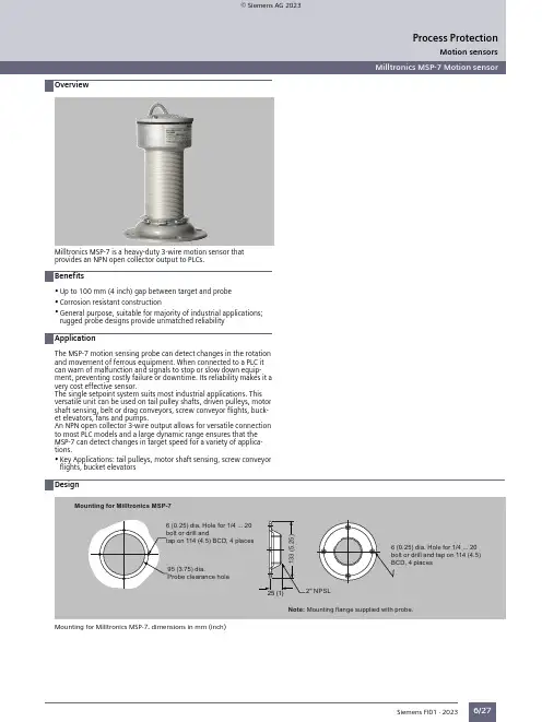
Motion sensorsOverviewMilltronics MSP-7 Motion sensorMotion sensorsMilltronics MSP-7 Motion sensor6/27Milltronics MSP-7 is a heavy-duty 3-wire motion sensor that provides an NPN open collector output to PLCs.•Up to 100 mm (4 inch) gap between target and probe •Corrosion resistant construction•General purpose, suitable for majority of industrial applications;rugged probe designs provide unmatched reliabilityThe MSP-7 motion sensing probe can detect changes in the rotation and movement of ferrous equipment. When connected to a PLC it can warn of malfunction and signals to stop or slow down equipment, preventing costly failure or downtime. Its reliability makes it a very cost effective sensor.The single setpoint system suits most industrial applications. This versatile unit can be used on tail pulley shafts, driven pulleys, motor shaft sensing, belt or drag conveyors, screw conveyor flights, bucket elevators, fans and pumps.An NPN open collector 3-wire output allows for versatile connection to most PLC models and a large dynamic range ensures that the MSP-7 can detect changes in target speed for a variety of applications.•Key Applications: tail pulleys, motor shaft sensing, screw conveyor flights, bucket elevatorsMounting for Milltronics MSP-7, dimensions in mm (inch)Siemens FI01 · 2023Process Protection© Siemens AG 2023Motion sensorsMilltronics MSP-7 Motion sensor6/281) No Y01 needed in Order code for standard length.Siemens FI01 · 2023Process ProtectionMotion sensorsMilltronics MSP-7 Motion sensor6/29Stand-alone probe Milltronics MSP-7, dimensions in mm (inch)Siemens FI01 · 2023Process Protection。
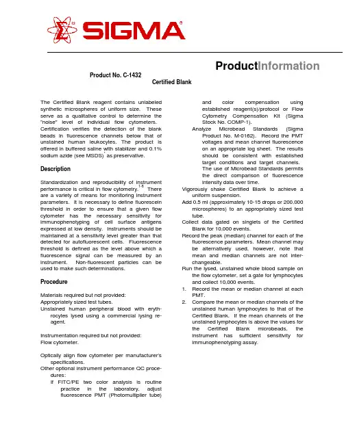
Product No. C-1432Certified BlankThe Certified Blank reagent contains unlabeled synthetic microspheres of uniform size. These serve as a qualitative control to determine the "noise" level of individual flow cytometers. Certification verifies the detection of the blank beads in fluorescence channels below that of unstained human leukocytes. The product is offered in buffered saline with stabilizer and 0.1% sodium azide (see MSDS)* as preservative. DescriptionStandardization and reproducibility of instrument performance is critical in flow cytometry.1-8 There are a variety of means for monitoring instrument parameters. It is necessary to define fluorescein threshold in order to ensure that a given flow cytometer has the necessary sensitivity for immunophenotyping of cell surface antigens expressed at low density. Instruments should be maintained at a sensitivity level greater than that detected for autofluorescent cells. Fluorescence threshold is defined as the level above which a fluorescence signal can be measured by an instrument. Non-fluorescent particles can be used to make such determinations.ProcedureMaterials required but not provided: Appropriately sized test tubes.Unstained human peripheral blood with eryth-rocytes lysed using a commercial lysing re-agent.Instrumentation required but not provided:Flow cytometer.Optically align flow cytometer per manufacturer’s specifications.Other optional instrument performance QC proce-dures:If FITC/PE two color analysis is routine practice in the laboratory, adjustfluorescence PMT (Photomultiplier tube)and color compensation usingestablished reagent(s)/protocol or FlowCytometry Compensation Kit (SigmaStock No. COMP-1).Analyze Microbead Standards (Sigma Product No. M-0162). Record the PMTvoltages and mean channel fluorescenceon an appropriate log sheet. The resultsshould be consistent with establishedtarget conditions and target channels.The use of Microbead Standards permitsthe direct comparison of fluorescenceintensity data over time.Vigorously shake Certified Blank to achieve a uniform suspension.Add 0.5 ml (approximately 10-15 drops or 200,000 microspheres) to an appropriately sized test tube.Collect data gated on singlets of the Certified Blank for 10,000 events.Record the peak (median) channel for each of the fluorescence parameters. Mean channel may be alternatively used, however, note that mean and median channels are not inter-changeable.Run the lysed, unstained whole blood sample on the flow cytometer, set a gate for lymphocytes and collect 10,000 events.1.Record the mean or median channel at eachPMT.pare the mean or median channels of theunstained human lymphocytes to that of the Certified Blank. If the mean channels of the unstained lymphocytes is above the values for the Certified Blank microbeads, the instrument has sufficient sensitivity for immunophenotyping assay.ProductInformationResultsThe Certified Blank should appear below (to the left of) unstained leukocytes. Each lot is accompanied by a lot-specific certificate verifying the expected mean channel values for a properly calibrated instrument. The Certified Blank serves as a qualitative control for monitoring flow cytometer sensitivity and the level of background fluorescent signals.Figure 1Fluorescence of the Certified Blank in the FITC PMT.Figure 2Autofluorescence of unstained lymphocytes in the FITC PMT.Figure 3Fluorescence of the Certified Blank in the PE PMT.Figure 4Autofluorescence of unstained lymphocytes in the PE PMT.LimitationsProper storage (2-8?C) and handling are essen-tial.This reagent is extremely sensitive to slight changes in pH. The Certified Blank microspheres are maintained at physiological pH (7.2). It is, therefore, critical that pH be carefully controlled in performing quantitative and qualitative flow cyto-metry analyses. Vigorously mixing microspheres prior to use is essential in obtaining a uniform suspension. Establishment of consistent, reproducible mean channel performance data for an appropriate reference standard, i.e., Microbead Standards, is crucial to proper interpretation of results obtained with Certified Blank.StorageStore at 2-8E C. Do Not Freeze.*Due to the sodium azide content a material safety data sheet (MSDS) for this product has been sent to the attention of the safety officer of your institution. Consult the MSDS for information regarding hazards and safe handling practices.References1.Proposed Guidelines: Clinical Applicationsof Flow Cytometry. Quality Assurance andImmunophenotyping of Peripheral BloodLymphocytes. National Committee forClinical Laboratory Standards. DocumentH42-P, 9, 13 (1989).1.Shapiro, H., Practical Flow Cytometry, 2ndEd., Alan R. Liss, Inc., New York, 267-270(1988).2.Keren, D., Flow Cytometry in Clinical Diag-nosis, ASCP Press, Chicago, 27-28 (1989).3.Horan, P., and M. Loken, "A Practical Guideto the Use of Flow Systems", In: Flow Cyto-metry Instrumentation and Data Analysis, M.Van Dilla, et al., (Eds.), Academic Press,NY, 260-280 (1985).4.Horan, P., and J. Kappler, J. Immunol.Meth., 18, 309 (1977).5.McCoy, J., et al., Am. J. Clin. Pathol., 93,Suppl. 1:S27-S37 (1990).6.Giorgi, J.V., et al., Clin. Immunol. Immunop-athol., 55, 173 (1990).7.Parker, J.W., et al., Clin. Immunol. Immuno-pathol., 55, 187 (1990).Sigma warrants that its products conform to the information contained in this and other Sigma publications. Purchaser must determine the suitability of the product for its particular use. See reverse side of invoice or packing slip for additional terms and conditions of the sale. Issued 08/95.。
FEATURES• Laser-based light scattering particle sensing • Concentration range: 0 µg/m 3 to 1,000 µg/m 3 • Fully calibrated• EMC: Heavy industrial level IEC61000• Response time: <6 s • Supply current: 80 mA max.• Output signal: UART (Universal Asynchronous Receiver/Transmitter)• PM2.5, PM10 output (standard); PM1.0, PM2.5, PM4.0, PM10 output (compact)• RoHS compliant • REACH compliantDIFFERENTIATION• Long life of 10 years offers a more stable operation for continuous usage• Proven EMC performance, based on IEC61000 stable operation, ±15% accuracy (PM2.5)POTENTIAL APPLICATIONS• HVAC (commercial and residential)• Indoor air quality monitors • Handheld air quality monitors• Air purifiers (commercial and residential)• Automotive cabin air purifiersAdvanced Sensing TechnologiesDESCRIPTIONThe Honeywell HPM Series Particulate Matter Sensor is a laser-based sensor which detects and counts particles using light scattering. The detection concentration range is 0 µg/m 3to 1,000 µg/m 3. A laser light source illuminates aparticle as it is pulled through the detection chamber. As particles pass through the laser beam, the light reflects off the particles and is recorded on the photo or light detector. The light is then analyzed and converted to an electrical signal to calculate particle concentration. The Honeywell particle sensor provides information on the particle concentration for given particle concentration range.VALUE TO CUSTOMERS• Enables the ability to more accurately and cost-competitively monitor or control environmental particulate • Industry-leading long life of 10 years of continuous use • Proven EMC performance enables the ability to perform more accurately in a variety of tough industrial environments• Faster response time of <6 s allows the HPM Series to respond to environmental conditions in real time• Enhanced reliability allows for use in harsh environmentsHPM SeriesParticulate Matter Sensors32322550Issue GStandardCompactlaser scattering HPMA115C0-003 HPMA115C0-004/ast3Advanced Sensing TechnologiesSignal to MCUFanLensLaser sourceLaser drive circuitLight trapConnector PhotodiodePhotoelectric converterAir outlet34212Shuts down the fan, helping to extend the life of the product. 3See Table 6 for data format./ast5Advanced Sensing Technologies12Shuts down the fan, helping to extend the life of the product. 3See Table 7 for data format./ast7Advanced Sensing Technologies/astFigure 2. Standard Mounting Dimensions and Correct Installation Orientations (For reference only. (mm/[in])Product InstallationInstall the product to the desired surface using the screw size shown in the applicable figure.NOTICEIMPROPER INSTALLATIONTo avoid particulate settling or accumulation at the air outlet or air inlet, which may affect product sensitivity and accuracy, ensure that the HPM Series Particle Sensor:• Is installed correctly according to Figure 2, 3, or 4.• Is installed such that the air inlet and air outlets are not blocked and that the flow of air through the sensor is neither reduced nor increased.9Advanced Sensing Technologies Figure 3. Compact Version HPMA115CO-003 Mounting Dimensions and Correct Installation Orientations (For reference only: mm/[in])Mount with three 1,8 [0.071] self-tapping screws; max. engagement is 3,5 [1.138].Correct Installation Orientations/astFigure 4. Compact Version HPMA115CO-004 Mounting Dimensions and Correct Installation Orientations (For reference only: mm/[in])Mount with three 1,8 [0.071] self-tapping screws; max. engagement is 3,5 [1.138].Correct Installation Orientations32322552-G-EN | G | 05/21© 2021 Honeywell International Inc. All rights reserved.HoneywellAdvanced Sensing Technologies 830 East Arapaho Road Richardson, TX /astFor more informationHoneywell Advanced SensingTechnologies services its customers through a worldwide network of sales offices and distributors. For application assistance, current specifications, pricing or the nearest Authorized Distributor, visit our website or call: Asia Pacific +65 6355-2828Europe+44 (0) 1698 481481USA/Canada +1-800-537-6945Warranty/RemedyHoneywell warrants goods of its manufacture as being free of defective materials and faulty workmanship during the applicable warranty period. Honeywell’s standard product warranty applies unless agreed to otherwise by Honeywell in writing; please refer to your order acknowledgment or consult your local sales office for specific warranty details. If warranted goods are returned to Honeywell during the period of coverage, Honeywell will repair or replace, at itsoption, without charge those items that Honeywell, in its sole discretion, finds defective. The foregoing is buyer’s sole remedy and is in lieu of all other warranties, expressed or implied, including those of merchantability and fitness for a particular purpose. In no event shall Honeywell be liable for consequential, special, or indirect damages.While Honeywell may provide application assistancepersonally, through our literature and the Honeywell web site, it is buyer’s sole responsibility to determine the suitability of the product in the application.Specifications may change without notice. The information we supply is believed to be accurate and reliable as of this writing. However, Honeywell assumes no responsibility for its use.ADDITIONAL INFORMATIONThe following associated literature is available on the Honeywell web site at :• Sell sheet• Frequently Asked Questions (FAQs)。
T 02:43:20+02:00Designación de tipo MIAD9W N° de identificación 3037718Modo de funcionamiento sensor de modo difuso Tipo de luzIRLongitud de onda 880 nm Alcance0…75 mm Temperatura ambiente-40… +70°CTensiónnom. 8.2 VDC Consumo de corriente (estado desactivado)ð 1.2 mA Consumo de corriente (estado activado)ï 2.1 mAFunción de salidafuncionamiento con luz, NAMUR Frecuencia de conmutación ð 100 HzIdentificación del aparato Ex II 1 G Ex ia IIC T5Modelo rectangular, Mini Beam Medidas51.8 x 12.3 x 30.7 mm Material de la carcasa plástico, PBT, amarillo Lente plástico, acrílico Conexióncable Longitud del cable2 mSección transversal del cable2 x 0.5mm Grado de protección IP67Tipo de protección "e"Ex ia IIC T5 Ga Hommologación Ex conforme a la certificación FM12ATEX0094X Indicación estado de conmutación LED rojoIndicación de exceso de gananciaLED rojo intermitentes homologación ATEX II 1 G s según EN 60947-5-6 (NAMUR)s cable, PVC, 2 ms grado de protección IP67sla sensibilidad se ajusta por medio del potenciómetro s indicador de ajustesTensión de servicio: 5…15 VCC (NA-MUR)s salida de conmutación bipolar sactivación con/sin luzEsquema de conexionesPrincipio de funcionamientoEl sensor de modo difuso contiene el emisor y receptor en una sola carcasa. Por ende, el sensor de modo difuso no detecta la interrup-ción del haz de luz, tal como el sensor de mo-do retro-reflectivo o opuesto, sino la reflexión del objeto. Un objeto se detecta si refleja sufi-ciente cantidad de luz de retorno al distancia de conmutación del sensor de modo difuso depende de la reflectividad del objeto.curva de alcanceAlta ganancia en relación con el alcanceT 02:43:20+02:00AccesoriosModelo N° de identi-ficación Dibujo acotadoSMB18A3033200escuadra de montaje, acero inoxidable, para sensores con rosca de 18mmSMB18AFAM103012558escuadra de montaje, material VA 1.4401, para rosca de 18mm, rosca M10 x 1,5SMB18SF 3052519escuadra de montaje, PBT negro, para sensores con rosca de 18mmSMB312B 3025519ángulo de montaje, acero inoxidable, para el modelo MI-NI-BEAM NAMURSMB3018SC 3053952escuadra de montaje, PBT negro, para rosca de 18 mmT 02:43:20+02:00Accessorios de funciónModeloN° de identi-ficación Dibujo acotadoIM1-22EX-R7541231amplificador-separador; dos canales; 2 salidas relé de cie-rre; entrada para señales NAMUR; control desconectable de rotura de hilo y cortocircuito; conmutable entre modo de co-rriente de trabajo y reposo; bloques de bornes extraíbles; an-cho de 18 mm; fuente de alimentación con rango de tensión ampliadoT 02:43:20+02:00Operating manual Uso correctoEste aparato cumple la directiva 94/9/CE y es apto para su aplicación en áreas potencialmente explosivas conforme a las normas EN60079-0:2009, -11:2012, -26:2007.Para un funcionamiento correcto es obligatorio cumplir las normas y disposiciones nacionales.Aplicación en áreas potencialmente explosivas, conforme a la clasificación II 1 G (grupo II, categoría 1 G, medio de servicio para atmósferas de gas)Identificación (véase aparato u hoja de datos)Ex II 1 G y Ex ia IIC T5 conforme a EN60079-0, -11 y -26Temperatura ambiente admisible en el lugar de aplicación -25…+70 °CInstalación / Puesta en servicioLos aparatos pueden ser montados, conectados y puestos en funcionamiento únicamente por personal cualificado. El personal cualificado debe poseer conocimientos sobre los tipos de protección e, las normas y los reglamentos relativos a medios de producción en áreas pruebe si la clasificación y la marcación sobre el aparato es apta para el caso concreto de aplicación.Este aparato es apropiado únicamente para la conexión en circuitos Exi certificados conforme a las normas EN60079-0 y -11. Observen los va-lores eléctricos máximos admisibles.Después de conectado a otros circuitos el sensor no podrá se utilizado ya en instalaciones Exi. En caso de conexión conjunta con medios de servicio (pertenecientes) se ha de llevar a cabo el "justificante de seguridad intrínseca" (EN60079-14).Instrucciones de instalación y montajeEvite las cargas estáticas en los aparatos y cables de plástico. Limpie el aparato sólo con un paño húmedo. No monte el aparato en corrientes de polvo y evite los depósitos de polvo sobre el mismo.Habrá de protegerse los aparatos si corren riesgo de daños mecánicos. Deberán estar protegidos asimismo contra los campos electromagnéti-cos fuertes.La distribución de los conductores y las magnitudes eléctricas figuran en la certificación del aparato o bien en la hoja de datos.No retire los capuchones de protección de las atornilladuras de los cables o de las clavijas hasta el momento de introducir los cables o de ator-nillar a la toma para protegerlos contra la suciedad.Reparación / MantenimientoNo es posible hacer reparaciones. La autorización se anula en caso de reparación o intervención en el aparato que no sea ejecutada por el fa-bricante. Se han ejecutado todos los datos del certificado del fabricante.。
SENSOR MOUNTING FOR USE WITH THE INTELLIGENT GAS SENSORS, iSERIES Application NoteContentsTurret Sealing 1PCB Mounting 2Recommended Spring Contact 2Flow Rate 3Minimum Flow Rate 3Recommended Design 4Turret Sealing: IP68 DesignThe front of the sensor is fit enough to withstand dust, sand, and dirt, along withbeing resistant to submersion up to a maximum depth of 1,5 m underwater for up tothirty minutes if the sensor is mounted using the recommended turret seal design.The O-ring around the sensor allows the user to seal the sensor and attain the IP68rating. Note that the rear of the sensor is not water-proof.The recommended turret dimensions for the bore diameter are from 17,56 mm (min)to 17,76 mm (max), and the surface finish must be longer than 3 mm, as depicted inFigure 1.Figure 1. iseries Sensor (Recommended Turret Dimensions)PCB MountingIf the sensor is mounted inside an instrument, it is required to allow a minimum space height under the cell; this height will depend on the connector. Depending on which of connector is used, the minimum height between the cell and PCB would change. Figure 2. iseries Sensor (Mounted Inside an Instrument)If the sensor is installed inside an instrument, the airpath of the gas is different to access the sensor; likewise, if an additional membrane is used on top of the sensor, the gas diffusion would be different. In general, if the gas dynamics change, the measured concentration value would also change. To compensate for this, it is necessary to change the user factor accordingly.The sensor/instrument coupling can be analysed by Honeywell, so the user factor can be determined accordingly. This would mean that once the user factor is assigned, the sensor would be ready to be set in your instrument (fully calibrated).AØ 17,76D e p e n d a n t o n Recommended spacer to prevent over compression of spring contact: Surface mount resistor size 1206Recommended PCB spring contact:ITT Cannon120220-0310(shown)A-A (1:1)BRecommended Spring ContactUnder no circumstances should intelligent sensor pads be soldered to, as this can cause leakage of electrolyte. Connection should be made via a mounting socket and spring connector., WARNING: SOLDERING TO PADS WILL RENDER YOUR WARRANTY VOID.Details of recommended spring connects are given below:Supplier:UK – CannonVEAM Jays Close, Viables EstateBasingstoke, RG22 4BAphone: +44.1256.311200fax: +44.1256.323356Micro Universal contact: uncompressed height: 1.1 mm, P0.4 SPCManufacturing part number: 120220-0348Flow RateMinimum Flow Rate RequiredA minimum flow rate is required to ensure accurate calibration - it also means that the response from a sensor is equivalent in configurations where gas is flowing over the sensor and those where the sample is allowed to diffuse to the sensor. The minimum flow which is required will be different depending on the sensor type.The reaction mechanism of sensors, consumes target gas - this means that the concentration of target gas will be depleted immediately in front of the sensor.The minimum flow rates are set so that, the sensor is exposed to a constant concentration of target gas - the flow rate is great enough to ensure that this depleted concentration is immediately replaced. This mimics the situation where the sample diffuses to the sensor; there will be a large volume of target gas so that the depletion is immediately replaced - via diffusion.Figure 3.ITT Spring Contact: 120220-0348002738-1-EN | 1 | 08/21HoneywellAdvanced Sensing Technologies 830 East Arapaho Road Richardson, TX 75081FOR MORE INFORMATIONHoneywell Advanced Sensing Technol-ogies services its customers through a worldwide network of sales offices and distributors. For application assistance, current specifications, pricing, or the nearest Authorized Distributor, visit /ast or call:USA/Canada +302 613 4491Latin America +1 305 805 8188Europe +44 1344 238258Japan +81 (0) 3-6730-7152Singapore +65 6355 2828Greater China+86 4006396841WARRANTY/REMEDYHoneywell warrants goods of itsmanufacture as being free of defective materials and faulty workmanship during the applicable warranty period. Honeywell’s standard product warranty applies unless agreed to otherwise by Honeywell in writing; please refer to your order acknowledgment or consult your local sales office for specific warranty details. If warranted goods are returned to Honeywell during the period ofcoverage, Honeywell will repair or replace, at its option, without charge those items that Honeywell, in its sole discretion,finds defective. The foregoing is buyer’s sole remedy and is in lieu of all other warranties, expressed or implied, including those of merchantability and fitness for a particular purpose. In no event shall Honeywell be liable for consequential, special, or indirect damages.While Honeywell may provide application assistance personally, through ourliterature and the Honeywell web site, it is buyer’s sole responsibility to determine the suitability of the product in the application.Specifications may change without notice. The information we supply isbelieved to be accurate and reliable as of this writing. However, Honeywell assumes no responsibility for its use.。
FLEXIM GmbHBoxberger Str. 412681 BerlinGermany电话: +49 (30) 93 66 76 60传真: +49 (30) 93 66 76 80保留不经事先通知变更的权利。
保留出错的权利。
是 FLEXIM GmbH 的注册商标。
网址: 电子邮件:***************Copyright (©) FLEXIM GmbH 2023传感器 用于 FLUXUS G7**TS _G7xx-transducersV1-1ZH_Leu, 2023-06-12G7**技术规格2023-06-12, TS _G7xx-transducersV1-1ZH_Leu2传感器选项. . . . . . . . . . . . . . . . . . . . . . . . . . . . . . . . . . . . . . . . . . . . . . . .3传感器订购代码. . . . . . . . . . . . . . . . . . . . . . . . . . . . . . . . . . . . . . . . . . . . . .6技术参数. . . . . . . . . . . . . . . . . . . . . . . . . . . . . . . . . . . . . . . . . . . . . . . . .7传感器固定件. . . . . . . . . . . . . . . . . . . . . . . . . . . . . . . . . . . . . . . . . . . . . . 20传感器的耦合材料. . . . . . . . . . . . . . . . . . . . . . . . . . . . . . . . . . . . . . . . . . . . 22阻尼材料 (可选). . . . . . . . . . . . . . . . . . . . . . . . . . . . . . . . . . . . . . . . . . . . 23阻尼垫. . . . . . . . . . . . . . . . . . . . . . . . . . . . . . . . . . . . . . . . . . . . . . . . . 23阻尼涂层. . . . . . . . . . . . . . . . . . . . . . . . . . . . . . . . . . . . . . . . . . . . . . . . 24连接系统. . . . . . . . . . . . . . . . . . . . . . . . . . . . . . . . . . . . . . . . . . . . . . . . 25接线盒. . . . . . . . . . . . . . . . . . . . . . . . . . . . . . . . . . . . . . . . . . . . . . . . . 27技术参数. . . . . . . . . . . . . . . . . . . . . . . . . . . . . . . . . . . . . . . . . . . . . . . . 27尺寸. . . . . . . . . . . . . . . . . . . . . . . . . . . . . . . . . . . . . . . . . . . . . . . . . . 282"管道安装组件. . . . . . . . . . . . . . . . . . . . . . . . . . . . . . . . . . . . . . . . . . . . .28技术规格 G7**3TS _G7xx-transducersV1-1ZH_Leu, 2023-06-12传感器选项步骤 1a选择兰姆波传感器:步骤 1b如果管道壁厚不在兰姆波传感器的范围内,则选择剪切波传感器:步骤 2管道内径 d 与管内流体的流速 v 有关从曲线中选择传感器(参见下一页)。
产品规格书品名:Smart dust微尘传感器型号:S7
(V1.2)
广州勒夫迈智能科技有限公司研发中心
目录
1.S7Smart Dust产品概述 (3)
1.1S7Smart Dust微尘传感器在吸尘器和扫地机器人产品的应用效益 (3)
1.2S7Smart Dust微尘传感器的产品特性 (3)
1.3应用领域 (4)
1.4基本特性 (4)
1.5接口定义 (5)
1.6应用电路 (6)
1.7数据传输 (7)
2.产品尺寸图 (7)
3.安装示意图 (8)
安装注意事项: (8)
附录1--S7Smart Dust微尘传感器UART数据说明 (9)
1.S7Smart Dust产品概述
S7Smart Dust微尘传感器产品利用光学的对射原理,可以精准地检测出经过吸尘器的手柄或延长杆管道、扫地机器人、抽油烟机、粒子检测仪器等设备的通风管道中的粒子数量和浓度数据。
1.1S7Smart Dust微尘传感器在吸尘器和扫地机器人产品的应用效益
◆设备的吸尘洁净效果和地面,地毯,床单等的洁净度,通过传感器输出数据和LED颜色显示直观地呈现给使用者;
◆设备根据传感器数据智能控制马达的转速,达到静音节能省电和延长马达寿命;
1.2S7Smart Dust微尘传感器的产品特性
◆产品为宽电压供电电压范围:12V--30V,可以直接用驱动马达的PWM 信号线为其供电;
◆产品采用发射和接收对射分离结构,具有体积小,便于用户在各种复杂的结构中灵活安装使用:接收主机L34*W30*H8.5mm,发射端L15*W7*H6.5;
◆运动测量精度高,风速12m/s时最小检测粒径10um;
◆测量灵敏度高,响应时间小于0.3s;
◆测量范围宽:0-999与0--9999两种选项量程;
◆功耗低:工作电流小于30mA,休眠电流小于0.5mA.
◆输出接口含有3PIN组成的7种颜色的颗粒浓度LED驱动电平,可以外接LED指示灯;
◆数据颗粒浓度输出接口:PWM,UART可以实时地为吸尘器、扫地机器人等设备提供准确的微尘浓度数据。
1.3应用领域
●吸尘器
●扫地机器人
●抽油烟机
●智能检测仪
1.4基本特性
传感器参数
参数指标单位
微尘测量范围≥5微米(μm)微尘质量浓度有效量程0~3000mg/m2
微尘质量浓度分辨率1mg/m2
单次响应时间≤0.3秒(s)
供电电源驱动马达的方波电压(12-30V)伏特(V)
工作电流≤30毫安(mA)待机电流≤0.5毫安(m A)数据接口电平L<0.8@3.3H>2.7@3.3伏特(V)
工作温度范围-10℃~+65℃(无结露)摄氏度(℃)工作湿度范围0~98%(非凝结)
储存温度范围-20℃~+80℃(无结露)摄氏度(℃)平均无故障时间≥5年(Y)
接口方式: 1.25mm*13P连接器
输出方式UART&PWM
接收主板尺寸34×30×8.5(传感器主体)毫米(mm)
<注意点>
●本产品原则上仅适用于上述应用领域,用作其他用途时,需要用户自行验证。
●本产品请尽量远离高频高压发生源,以避免因高频高压造成的干扰。
●无规则的剧烈震动会造成本产品测量误差增大。
●外界光会造成本产品的测量误差增大,因此安装于设备时,应尽量避免外
界光的射入。
1.5接口定义
PIN13PIN1
PIN1VCC外部电源输入
PIN2GND电源地
PIN3SET 设置管脚/TTL电平@3.3V,高电平或悬空为正常工作状态,低电平为休眠状态
PIN4RX串口接收管脚/TTL电平@3.3V
PIN5TX串口发送管脚/TTL电平@3.3V
PIN6RESET模块复位信号/TTL电平@3.3V,低复位
PIN7预留
PIN8PWM脉宽调制信号输出
PIN9GND电源地
PIN10VDD输出电源正3.3VDC负载20mA Max@25VDC输入PIN11R三基色LED-R驱动输出
PIN12G三基色LED-G驱动输出
PIN13Y三基色LED-Y驱动输出
1.6应用电路
电路设计应注意:
1.S7输出接口的数据通讯和控制管脚均需要3.3V作为高电平。
(主板MCU为5V
供电,需要在通讯线(RXD、TXD)和控制线(SET、RESET)上加入电平转换芯片或电路)
2.SET和RESET内部有上拉电阻,如果不使用,则应悬空。
3.PIN7为程序内部调试用,应用电路中应使其悬空。
4.传感器VDD输出电压+3.3VDC,负载电流20mA Max。
5.R\G\Y驱动输出需要连接外围转换电路实现,如:图1电路仅作参考。
图1
1.7数据传输
UART输出
传感器采用标准全双工UART串口通信,波特率为9600bps,在应用过程中,只需接收微尘浓度数据,传感器默认状态下为持续工作,串口数据解码后得到微尘浓度值,单位为mg/m²。
详细的串口通信格式及数据解码参见《附录1》。
PWM输出
传感器通过PWM口输出PWM信号,该PWM周期为1S,按低电平宽度计算微尘浓度值。
低脉冲时间与微尘浓度的关系:1ms=1mg/m²。
例如低电平宽度为100ms,则对应灰尘浓度为100mg/m²。
PWM浓度输出范围为5mg/m²~800 mg/m²。
2.产品尺寸图
单位:mm.发射管部分
接收部分
3.安装示意图
安装注意事项:
●发射管与传感器主体通过线材连接;
● 安装发射管和接收管时,应采取减振措施,尽量避免振动;●应保证发射管与接收管之间呈现180°;●发射管与接收管的距离应小于等于60mm;
附录1--S7Smart Dust 微尘传感器UART 数据说明
1.UART 参数:
默认波特率:9600bps 位数:8Bit 校验位:无停止位:1位
2.主机通讯协议格式特征字节1特征字节2指令字节状态字节1状态字节
2
校验字节1校验字节20x420x4D
CMD
DATAH DATAL LRCH LRCL
3.指令及特征字节定义CMD DATAH DATAL
说明
0xE2X X
被动式读数0xE1X 00H-被动式01H-主动式状态切换0xE4
X
00H-待机模式01H-正常模式
待机控制
4.指令应答:
0xE2:应答32字节,同采样数据类型协议。
5.校验字生成
从特征字开始所有字节累加和。
发射管部分
180°对射
安装管道部分
接收部分
180°对射
连接线
6.采样数据类型总长度:32字节
起始符10x42(固定)
起始符20x4D(固定)
帧长度高八位……帧长度=2x13+2(数据+校验位)
帧长度低八位……
数据1高八位……数据1表示等效螨虫粒径颗粒物个数
(识别率≥90%)
数据1低八位……
数据2高八位……数据2表示PM20浓度
mg/m²
数据2低八位……
数据3高八位……数据3表示PM30浓度
mg/m²
数据3低八位……
数据4高八位……数据4表示PM50浓度
mg/m²
数据4低八位……
数据5高八位……数据5表示微尘总浓度
mg/m²
数据5低八位……
数据6高八位……保留
数据6低八位……
数据7高八位……保留
数据7低八位……
数据8高八位……保留
数据8低八位……
数据9高八位……保留
数据9低八位……
数据10高八位……保留
数据10低八位……
数据11高八位……保留
数据11低八位……
数据12高八位……保留
数据12低八位……
数据13高八位……版本号
数据13低八位……错误代码
数据和校验高八位……校验码=起始符1+起始符2+……..+数据13低
八位
数据和校验低八位……
注:用户一般取数据5的高低八位为最终的微尘总浓度。