硫氮掺杂碳纳米管
- 格式:pdf
- 大小:2.11 MB
- 文档页数:8
化工进展 2016年第35卷·830·由图7可以看出,剂油质量比对焦化蜡油脱氮效果影响显著,对精制油收率的影响不大。
当剂油质量比为1∶2时,脱氮率为64.46%。
当剂油质量比为1∶4时,脱氮率达到最大为88.04%。
剂油质量比增大,增加了吸附剂的量,也增加了吸附剂上磷钨酸活性位点,即增加了焦化蜡油中碱性氮化物与吸附剂酸活性位的接触机会,使脱除的碱性氮化物增多,脱氮率逐渐升高。
剂油比继续增大时,脱氮率逐渐下降,这可能是由于剂油比逐渐增大,增加了焦化蜡油中烃类与负载型磷钨酸活性位点接触机会,与吸附剂上碱性氮化物的吸附产生竞争吸附,使单位吸附剂上氮化物的吸附量相应减少,脱氮率下降。
因此,最佳脱氮率的剂油质量比为1∶4。
3 结论本研究进行了负载型杂多酸吸附剂脱除焦化蜡油中碱性氮化物的实验,得出如下结论。
(1)实验用硅胶负载杂多酸制备吸附剂,负载型磷钨酸吸附剂的红外光谱图表明,硅胶成功负载了Keggin型磷钨酸。
氮气吸附-脱附等温线表明,吸附剂有介孔材料的特征,都具有介孔孔道,表明负载型磷钨酸吸附剂是一种理想的脱氮吸附剂。
(2)实验用非加氢处理方法的吸附脱氮法脱除焦化蜡油中碱性氮化物,得到了焦化蜡油脱氮的最佳工艺条件。
以活化硅胶负载磷钨酸作为吸附剂、磷钨酸负载质量分数为40%、吸附温度为50℃、吸附时间为50min、剂油质量比为1∶4的条件下,焦化蜡油中的碱性氮化物的脱除率为89.07%,收率为95.54%。
吸附脱氮法操作简单,效果明显,吸附剂可有效脱除焦化蜡油中的碱性氮化物。
参考文献[1] 马丽娜,马守涛,刘丽莹,等. 焦化蜡油络合脱氮-催化裂化组合工艺研究[J]. 石油与天然气化工,2011,4(6):571-573. [2] 温世昌,周亚松,魏强. 焦化蜡油中含氮化合物的加氢反应性能[J]. 石油学报(石油加工),2008,24(5):496-502.[3] 陈文艺,栾锡林,关毅达. 我国焦化蜡油的组成和特性[J]. 石油化工,2000(8):607-612.[4] 袁起民,王屹亮,山红红,等. 焦化蜡油催化裂化产物氮分布的研究[J]. 燃料化学学报,2007,35(3):375-379.[5] 徐晓宇,孙悦,沈健,等. HY和USY分子筛对模拟油品中碱性氮化物的吸附行为[J]. 化工进展,2014,33(4):1035-1040. [6] SONG C S. An overview of new approaches to deep desulfurizationfor ultra-clean gasoline,diesel fuel and jet fuel[J]. Catalysts Today,2003,86 :211-263.[7] 张海燕,代跃利,蔡蕾. 杂多酸催化剂催化氧化脱硫研究进展[J].化工进展,2013,32(4):809-815.[8] 丁巍,王鼎聪,赵德智,等. 纳米自组装催化剂金属分散度对催化活性的影响[J]. 现代化工,2014,34(5):113-116.[9] 于光林,周亚松,魏强,等. 辽河焦化蜡油中碱性氮化物的脱除[J]. 化工进展,2011,30(s1):104-106.[10] BAUSERMAN J W,NGUYEN K M,MUSHRUSH G W. Nitrogencompound determination and distribution in three source fuels byGC/MS[J]. Petroleum Science and Technology,2004,22(11/12):1491-1505.[11] 廖爱玲. 2018年全国车用汽油全部达到国5标准[J]. 中国石油和化工标准与质量,2013(16):2.[12] 孙敬军,修彭浩,从日明,等. 焦化蜡油活化树脂吸附脱氮及反应性能的研究[J]. 石油与天然气化工,2014,43(3):234-240. [13] YADAY G D,MISTRY C K. Oxidation of benzyl alcohol under asynergism of phase transfer catalysis and heterpolyacids[J]. Journal ofMolecular Catalysis A:Chemical,2001,172(1/2):135-149. [14] WANG J,ZHU H O. Alkylation of l-dodecene with benzene overH3PW12O40 supported on mesoporous silica SBA-15[J]. CatalysisLetters,2004,93(3/4):209-212.[15] 张海燕,代跃利,蔡蕾. 杂多酸催化剂催化氧化脱硫研究进展[J].化工进展,2013,32(4):809-815.[16] 于海云. 负载型杂多酸催化剂的制备、表征及催化性能研究[D].通辽:内蒙古民族大学,2012:1-7.[17] STAITI P,FRENI S,HOCEV AR S,et al. Synthesis andcharacterization of proton-conducting materials containing dodecatungstophosphoric and dodecatungstosilic acid supported onsilica[J]. Journal of Power Sources,1999,79(2):250-255. [18] 陈霄榕,李永丹. SiO2与Keggin杂多酸相互作用的研究[J]. 分子催化,2002,16(1):60-64.[19] 冯锡兰,彭慧慧,柳云骐,等. 负载型杂多酸催化甲苯异丙基化反应[J]. 化工进展,2014,33(12):3263-3269.[20] 付辉,李会鹏,赵华,等. WO3-ZSM-5/MCM-41用于FCC汽油催化氧化脱硫工艺研究[J]. 精细石油化工,2013,30(6):19-22.2016年第35卷第3期CHEMICAL INDUSTRY AND ENGINEERING PROGRESS ·831·化工进展氮掺杂对碳材料性能的影响研究进展张德懿,雷龙艳,尚永花(兰州理工大学石油化工学院,甘肃兰州 730050)摘要:碳材料是目前研究和应用最为广泛的一类无机非金属材料。
![一种可控的氮掺杂碳纳米管的制备方法[发明专利]](https://uimg.taocdn.com/6524b7fb59eef8c75ebfb32a.webp)
专利名称:一种可控的氮掺杂碳纳米管的制备方法专利类型:发明专利
发明人:夏晖,郭秋卜,杨梅,翟腾
申请号:CN201710235593.3
申请日:20170412
公开号:CN108689398A
公开日:
20181023
专利内容由知识产权出版社提供
摘要:本发明公开了一种可控的氮掺杂碳纳米管的制备方法。
该方法首先将金属盐、碳源和氮源溶于水或乙醇溶液中,60‑80℃下搅拌至溶液挥发形成溶胶,再将溶胶置于80‑120℃下干燥形成凝胶,最后将凝胶状前驱体进行高温热处理碳化,在350‑650℃下保温2‑4h,再在750‑1000℃下保温5‑10h,得到含金属或金属硫化物的掺氮碳纳米管,简单的腐蚀后即得掺氮碳纳米管。
本发明的溶
胶‑凝胶法能够实现对掺氮碳纳米管管径和管长的有效调控,氮含量、孔结构和导电性均可调节。
本发明制备的氮掺杂碳纳米管应用于电池的电极材料中,有效提高了电池的循环寿命,具有良好的电化学性能,有望应用在电化学催化、能源转换及储能等领域。
申请人:南京理工大学
地址:210094 江苏省南京市孝陵卫200号
国籍:CN
代理机构:南京理工大学专利中心
代理人:刘海霞
更多信息请下载全文后查看。
氮掺杂碳纳米管
氮掺杂碳纳米管是一种新型的纳米材料,具有优异的物理和化学性质,其应用前景广阔。
本文将从氮掺杂碳纳米管的制备、性质和应用方面进行介绍,希望对读者有所启发。
首先,氮掺杂碳纳米管的制备方法多种多样,可以通过化学气相沉积、化学气相沉积-电弧放电、电化学氧化还原、溶胶凝胶法等多种方法制备。
其中,化学气相沉积方法制备出来的氮掺杂碳纳米管具有尺寸均一、晶格结构完整的特点。
其次,氮掺杂碳纳米管的性质也非常出色。
由于氮原子的掺杂会导致碳纳米管的电子结构发生改变,使得氮掺杂碳纳米管具有比纯碳纳米管更优异的电催化活性、电化学性能、光催化性能、导电性、机械强度等性质。
因此,氮掺杂碳纳米管可以广泛应用于能源转换、催化反应、电子器件、生物医学等领域。
最后,氮掺杂碳纳米管的应用前景非常广阔。
在能源转换方面,氮掺杂碳纳米管可以作为光催化材料用于制备高效的太阳能电池和水分解催化剂,作为电催化材料用于制备高性能的燃料电池和电化学超级电容器。
在催化反应方面,氮掺杂碳纳米管可以作为催化剂用于制备高效的有机合成和环境治理。
在电子器件方面,氮掺杂碳纳米管可以作为高性能的导电材料用于制备柔性电子器件。
在生物医学方面,氮掺杂碳纳米管可以作为纳米药物载体、光热治疗剂和分子成像探针用于癌症治疗和分子诊断。
总之,氮掺杂碳纳米管是一种非常有前途的纳米材料,其制备、性质和应用方面都有着广泛而深远的研究价值和实际应用意义。
我们相信,在未来的科技进步和人类文明进程中,氮掺杂碳纳米管将会发挥越来越重要的作用。
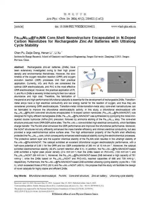
物 理 化 学 学 报Acta Phys. -Chim. Sin. 2024, 40 (2), 2304021 (1 of 2)Received: April 10, 2023; Revised: May 22, 2023; Accepted: May 23, 2023; Published online: June 8, 2023.*Correspondingauthors.Emails:***********.cn(H.L.);****************.cn(L.X.);Tel.:+86-511-88799500(L.X.).The project was supported by the National Natural Science Foundation of China (22178148, 22278193).国家自然科学基金(22178148, 22278193)资助项目 © Editorial office of Acta Physico-Chimica Sinica[Article] doi: 10.3866/PKU.WHXB202304021 Fe 0.64Ni 0.36@Fe 3NiN Core-Shell Nanostructure Encapsulated in N-Doped Carbon Nanotubes for Rechargeable Zinc-Air Batteries with Ultralong Cycle StabilityChen Pu, Daijie Deng, Henan Li *, Li Xu *Institute for Energy Research, School of Chemistry and Chemical Engineering, Jiangsu University, Zhenjiang 212013, Jiangsu Province, China.Abstract: Rechargeable zinc-air batteries (ZABs) havebeen extensively investigated owing to their high powerdensity and environmental friendliness. However, the slowkinetics of the oxygen reduction reaction (ORR) and oxygenevolution reaction (OER) processes limit their practicalapplication. Currently, IrO 2 and RuO 2 are considered theoptimal OER electrocatalysts, and Pt/C is the most effectiveORR electrocatalyst. However, the practical application of Pt,Ir, and Ru in ZABs is severely limited owing to their low naturalabundance and high cost. Therefore, the fabrication ofinexpensive and high-performance bifunctional catalysts is essential for the development of rechargeable ZABs. Transition-metal alloys have a high electrical conductivity and low energy barrier for the reaction of oxygen, and thus they are considered promising ORR electrocatalysts. Transition-metal nitride-transition-metal alloy core-shell nanostructures can be fabricated to improve the bifunctional electrocatalytic activity. In this study, a bifunctional electrocatalyst with Fe 0.64Ni 0.36@Fe 3NiN core-shell structures encapsulated in N-doped carbon nanotubes (Fe 0.64Ni 0.36@Fe 3NiN/NCNT) was designed for highly efficient rechargeable ZABs. Fe 0.64Ni 0.36@Fe 3NiN/NCNT was synthesized by pyrolyzing the nickel-iron-layered double hydroxide (NiFe-LDH) precursor, followed by ammonia etching of the Fe 0.64Ni 0.36 alloy. The core-shell structure produced more ORR/OER active sites. The Fe 0.64Ni 0.36 core exhibited high electrical conductivity, which facilitates charge transfer. The Fe 3NiN shell enhanced the OER performance and improved the bifunctional performance. Moreover, the NCNT structures not only efficiently enhanced the mass transfer efficiency and intrinsic electrical conductivity, but also provided a large electrochemical active surface area. The high anticorrosion property of the Fe 3NiN shell effectively protected the Fe 0.64Ni 0.36 core, which consequently enhanced electrocatalyst stability during the electrochemical processes. The protective carbon layer and the superior chemical stability of the Fe 3NiN shell resulted in the ultrahigh stability of Fe 0.64Ni 0.36@Fe 3NiN/NCNT. The catalyst exhibited an excellent bifunctional oxygen electrocatalytic performance, with a half-wave potential of 0.88 V for the ORR and low OER overpotential of 380 mV at 10 mA ∙cm −2. Moreover, the catalyst exhibited electrochemical stability (92.8% current retention after 8 h). In addition, the Fe 0.64Ni 0.36@Fe 3NiN/NCNT-based ZAB exhibited a higher peak power density (214 mW ·cm −2) than the ZABs based on Pt/C+IrO 2 (155 mW ·cm −2) and Fe 0.64Ni 0.36/NCNT (89 mW ·cm −2). Moreover, the Fe 0.64Ni 0.36@Fe 3NiN/NCNT-based ZAB delivered a high capacity of 781 mAh ·g −1, while the ZABs based on Fe 0.64Ni 0.36/NCNT and Pt/C+IrO 2 reached capacities of 688 and 739 mAh ·g −1, respectively. Furthermore, the Fe 0.64Ni 0.36@Fe 3NiN/NCNT-based ZAB exhibited ultralong cycling stability (cycle life > 1100 h), which exceeded those of Pt/C (50 h) and Fe 0.64Ni 0.36/NCNT (450 h). We propose that this study will facilitate the design of novel catalysts for highly stable and efficient ZABs.Key Words: Bifunctional electrocatalyst; Fe 3NiN; Core-shellstructure; Zinc-air battery; Ultra-long cycle stability物理化学学报 Acta Phys. -Chim. Sin.2024,40 (2), 2304021 (2 of 2)氮掺杂碳纳米管包覆Fe0.64Ni0.36@Fe3NiN核壳结构用于高稳定锌-空气电池蒲晨,邓代洁,李赫楠*,徐丽*江苏大学能源研究院,化学化工学院,江苏镇江 212013摘要:可逆锌-空气电池因其高功率密度和环境友好性而得到了广泛研究。
氮掺杂的碳纳米管分子式
氮掺杂的碳纳米管分子式是N-CNT。
碳纳米管是一种具有优异性能和广泛应用前景的纳米材料。
通过在碳纳米管结构中引入氮原子,可以改变碳纳米管的电子结构和化学性质,进一步拓展其应用领域。
氮掺杂可以通过不同的方法实现,如氨气化学气相沉积、氮气等离子体处理、热解过程中与氮源共存等。
氮原子与碳原子的结合方式可以分为氮化碳和氮酸碳两种形式。
氮化碳是指氮原子取代了碳纳米管的碳原子,可以通过控制氮掺杂的浓度和位置来调控碳纳米管的电学性能。
氮酸碳是指氮原子与碳原子之间形成的化学键连接,可以增加碳纳米管的导电性能和电催化活性。
氮掺杂的碳纳米管具有许多优异性能和应用潜力。
首先,氮掺杂可以调节碳纳米管的电子结构,使其在能带结构和导电性能上有所改善。
其次,氮原子的引入可以增加碳纳米管的活性位点,提高其催化活性,从而应用于电催化、光催化、电化学传感等领域。
此外,氮掺杂还可以增加碳纳米管的化学反应活性,如在氮掺杂的碳纳米管上进行催化反应、吸附等。
总之,氮掺杂的碳纳米管是一种具有潜力的纳米材料,其分子式为N-CNT。
通过氮掺杂可以调控碳纳米管的电子结构和化学性质,进一步增强其性能和拓展其应用领域。
这为碳纳米管在能源、光电子、催化等领域的应用提供了新的可能性。
![一种氮掺杂MoCCo碳纳米管复合材料及其制备方法与应用[发明专利]](https://uimg.taocdn.com/35a44017effdc8d376eeaeaad1f34693daef10f2.webp)
专利名称:一种氮掺杂MoC/Co/碳纳米管复合材料及其制备方法与应用
专利类型:发明专利
发明人:原长洲,赵国强,刘洋,侯林瑞
申请号:CN202111646895.2
申请日:20211230
公开号:CN114300668A
公开日:
20220408
专利内容由知识产权出版社提供
摘要:本发明公开一种氮掺杂MoxC/Co/碳纳米管复合材料及其制备方法与应用。
所述复合材料包括氮掺杂的二维片状MoxC基体以及原位生长在该基体表面上氮掺杂碳的纳米管组成的三维结构。
本发明的氮掺杂MoxC/Co/碳纳米管复合材料兼具一维碳纳米管和二维片状的形貌结构,不仅保持了二维MXene的催化特性,而且碳纳米管的引入提高了材料的导电性。
另外,本发明的氮掺杂MoxC/Co/碳纳米管复合材料具有大的比表面积,其能够提供更多的多硫化物吸附位点,抑制多硫化物的扩散,从而抑制锂硫电池的“穿梭效应”,显著提高了锂硫电池的能量密度和循环寿命。
申请人:济南大学
地址:250000 山东省济南市南辛庄西路336号
国籍:CN
代理机构:山东知圣律师事务所
代理人:陈辉
更多信息请下载全文后查看。
氮掺杂碳纳米管的制备及性质研究氮掺杂碳纳米管(Nitrogen-doped carbon nanotubes,NCNTs)作为晶体管导电材料、电极催化剂等领域具有广泛的应用前景。
NCNTs与传统碳纳米管相比,其电学性能、导电性及化学反应活性等方面得到了显著提升,便成为研究热点。
本文将对氮掺杂碳纳米管的制备方法及性质进行探究。
1. 氮掺杂碳纳米管制备方法目前,氮掺杂碳纳米管的制备方法主要有以下几种:(1)碳源法碳源法是目前制备NCNTs最常用的方法。
通过在碳源中引入含氮原料,例如尿素、三氯甲基胺等,掺杂到碳纳米管中,就可实现氮掺杂。
同时,还可通过溶胶-凝胶法、水热法等方法,在碳源中掺杂金属催化剂,有助于控制碳纳米管的形貌和尺寸。
(2)VLS法在VLS法中,金属催化剂通过在有机蒸汽中的裂解,使碳纳米管从金属颗粒上成长。
通过在气相中同时加入金属源和含有氮源的化合物,就可获得掺杂氮原子的碳纳米管。
(3)CVD法CVD法是一种利用金属催化剂在高温下,将气态前体分解形成碳纳米管的方法。
在此基础上,掺杂氮元素的方法与碳源法相同,可在反应体系中加入含有氮源的化合物。
2. NCNTs的性质研究(1)电学性能与传统碳纳米管相比,掺杂有少量氮元素的碳纳米管,具有较高的导电性和载流子浓度。
通过对NCNTs进行掺杂和改性等手段,可以调控其电学性能。
例如,不同掺杂比例的碳纳米管在电导率上有着明显的区别。
此外,NCNTs还具有比传统碳纳米管更宽的带隙,这是其在半导体器件领域应用的优势之一。
(2)催化性能NCNTs的催化性能也受到广泛关注。
含氮原子的掺杂使得碳纳米管表面功能团发生改变,增加了纳米管的活性和催化能力。
例如,NCNTs在电极催化剂、有机污染物的氧化降解等领域,有着较高的催化活性和稳定性。
(3)应用前景由于其优越的化学和物理特性,NCNTs在电池、超级电容器、催化剂、传感器等应用领域发挥了重要作用。
近年来,NCNTs还被发现在细胞成像和生物探针等领域使用。
氮掺杂炭层包覆碳纳米管的组织结构调控及其氧还原催化活性李莉香;赵宏伟;邢天宇;耿新;宋仁峰;安百钢【摘要】Polypyrrole-coated carbon nanotubes ( PPy-CNTs ) synthesized by an in-situ chemical polymerization approach were heat-treated at 600, 800 and 1000 ℃ in N2 to prepare N-doped carbon coatings on CNTs (NC-CNTs). The specific surface area ( SSA) and pore volume of the NC-CNTs increase significantly with heat treatment temperature and the nitrogen content decreases. Also, as the temperature increases the content of pyrrolic-N decreases while that of the graphitic-N increases. The SSA and pore vol-ume of the NC-CNT1000 are 3 and 1. 7 times higher than those of the NC-CNT600. As metal free electrocatalysts, the NC-CNTs show significant ORR activity in a basic electrolyte, but it is not proportional to their total nitrogen content. The ORR mechanism of the NC-CNT600 and NC-CNT800 belongs to a two-electron transfer reaction while that of the NC-CNT1000 to a mixture of the two-electron and four-electron transfer reactions. The NC-CNT1000 exhibits the best ORR activity and durability among the samples ow-ing to its highest SSA and pore volume as well as having the largest amount of graphitic-N.%采用化学原位聚合合成聚吡咯涂覆碳纳米管,之后将其在氮气氛下热处理制备氮掺杂炭层包覆碳纳米管NC-CNTs.利用该工艺,通过改变热处理温度,调控NC-CNTs组织结构和表面化学组成.比表面和孔结构分析显示,600,800和1000℃热处理制备的氮掺杂碳纳米管NC-CNT600,NC-CNT800和NC-CNT1000的比表面积和孔体积依次显著增加,NC-CNT1000的比表面积和孔体积分别约是NC-CNT600的3倍和1.7倍.这是因碳纳米管表面聚吡咯层向氮掺杂炭层转化过程导致更多的微孔形成.然而,制备温度升高使NC-CNTs的氮含量降低,表面含氮官能团由吡咯型氮向吡啶型氮和石墨氮转化,NC-CNT1000含最高比例的石墨氮.作为无金属催化剂,NC-CNTs在碱性电解质条件下展现了明显的氧还原催化活性,但其氧还原活性并不与样品氮含量成正比.NC-CNT600和NC-CNT800的氧还原反应为两电子转移机制,而NC-CNT1000表现为两电子和四电子转移混合机制,其展现出最高的氧还原催化活性和催化稳定性,这可能是其具有高的比表面积和孔体积,结合含氮官能团中高比例石墨氮的缘故.【期刊名称】《新型炭材料》【年(卷),期】2017(032)005【总页数】8页(P419-426)【关键词】氮掺杂;碳纳米管;氧还原;氮官能团【作者】李莉香;赵宏伟;邢天宇;耿新;宋仁峰;安百钢【作者单位】辽宁科技大学化学工程学院, 辽宁鞍山 114051;辽宁科技大学材料电化学研究所, 辽宁鞍山 114051;辽宁科技大学化学工程学院, 辽宁鞍山 114051;辽宁科技大学化学工程学院, 辽宁鞍山 114051;辽宁科技大学化学工程学院, 辽宁鞍山 114051;辽宁科技大学材料电化学研究所, 辽宁鞍山 114051;鞍钢集团矿业设计研究院,辽宁鞍山 114004;辽宁科技大学化学工程学院, 辽宁鞍山 114051;辽宁科技大学材料电化学研究所, 辽宁鞍山 114051【正文语种】中文【中图分类】O646随着石化资源临近枯竭和其低效使用带来的环境污染加剧, 开发绿色清洁能源日益迫切。
氮掺杂碳纳米管活化过-硫酸盐降解酸性橙AO7王莹;魏成耀;黄天寅;吴玮;陈家斌【摘要】采用氮掺杂多壁碳纳米管(N-CNT)作为固体活化剂,活化过—硫酸盐(PMS)氧化降解偶氮染料酸性橙7(AO7).结果表明,N-CNT活化PMS降解AO7比颗粒活性炭(GAC)效果好,N-CNT投加量为400mg/L、n(PMS)/n(AO7)为40/1时,反应60min可使AO7的脱色率达到99%;研究了N-CNT活化PMS降解AO7的降解机制,发现N-CNT活化PMS产生的自由基主要是SO4-·,活化场所在N-CNT的表面.在N-CNT/PMS体系中,初始pH值对降解AO7有较大的影响,当pH=3.0时AO7降解效果最好;Cl、SO42-和CO32-离子对AO7降解都存在一定促进作用,离子浓度越高,AO7降解速率越快.紫外可见光谱、TOC分析表明AO7分子中偶氮键及萘环结构均被破坏,并进一步矿化为CO2和H2O.%Nitrogen-doped carbon nanotube (N-CNT) was used as an activator to activate peroxymonosulfate (PMS) to degrade azo dye,Acid orange 7 (AO7) in aqueous solution.The results indicated that N-CNT exhibited a much better performance on activating PMS to decolorize AO7 than activated carbon (GAC),the removal of AO7 could reach 99% after 60min with 400mg/L of N-CNT dosage,40/lof PMS/AO7 molar ratio.The degradation mechanism of AO7 in N-CNT activated PMS system was explored,and SO4-· was found to be dominantly responsible for AO7 degradation,which mainly took place on the surface of N-CNT.The The initial pH had a significant effect on the AO7 degradation,and pH 3.0 was most favorable for its degradation.In addition,the degradation of AO7 was accelerated after addition of Cl-、SO42-and CO32-;From the analysis of UV-vis spectra and TOC analysisindicated that the azo band and naphthaline ring of AO7 that were destructed and then mineralized into CO2 and H2O.【期刊名称】《中国环境科学》【年(卷),期】2017(037)007【总页数】8页(P2583-2590)【关键词】氮掺杂碳纳米管;过一硫酸盐;酸性橙7【作者】王莹;魏成耀;黄天寅;吴玮;陈家斌【作者单位】苏州科技大学环境科学与工程学院,江苏苏州215009;苏州科技大学环境科学与工程学院,江苏苏州215009;苏州科技大学环境科学与工程学院,江苏苏州215009;苏州科技大学环境科学与工程学院,江苏苏州215009;苏州科技大学环境科学与工程学院,江苏苏州215009【正文语种】中文【中图分类】X703;X131.2偶氮染料是分子结构中含有一个或多个偶氮基(–N=N–)的染料,其生产废水具有毒性强、含盐量高、致突变、致癌、难降解等特点[1-2],不经处理直接排放会对环境造成严重污染.偶氮染料废水常用的处理方法有吸附[3]、膜过滤[4]、光催化[5-6]、臭氧化[7-8]等.近年来,基于硫酸根自由基的高级氧化技术对偶氮染料氧化降解作用明显[9-10].硫酸根自由基有较高的氧化还原电位(E0= 2.5~3.1V),可以氧化降解大部分有机污染物[11].过硫酸盐(PS)和过一硫酸盐(PMS)是能够产生的常用氧化剂,在常温下比较稳定很难分解,但在加热[12-14]、紫外光照射[15-16]、过渡金属离子[4,17-19]等条件下,能够被活化产生诸多研究表明用颗粒活性炭(GAC)能有效活化PS或PMS 降解偶氮染料废水[19-21].普通碳纳米管(CNT)因具有比表面积大、热稳定性高、独特管腔和吸附特性以及特有的电学特性等性质,已作为新型催化材料引起了人们的极大兴趣,取得了广泛的应用,例如在其力学性能方面,CNT的强度比其他纤维强度约高 200倍,加之CNT的韧性很好,使其可以广泛应用于微米甚至纳米机械;同时,CNT还是一种新型超导材料,具有很高的临界超导电流,这为热敏电阻辐射器件的研制和开发提供了条件.目前,CNT的制备方法主要有石墨电弧法、激光蒸发法和催化热解法.当碳纳米管掺入氮(N-CNT)之后,改变了碳原子周围的电子云密度,使其具有良好的电子传导性,其电子效应也在催化材料方面展示出独特性能.目前,氮掺杂碳纳米管的制备方法可以分为3:(1)同步原位掺杂,即在CNT生成过程中进行掺杂; (2)高温碳化含氮高分子; (3)在含氮条件下,对碳纳米管进行后处理,如采用等离子体、水热等方法进行氮掺杂.氮掺杂将影响CNT的状态密度、微分电容、体电导率和功函数等电化学及电子性质,使得碳纳米管可实现较低电位下氧的吸附解离,从而具有氧化还原反应催化活性.碳纳米管具有独特的电学,机械和结构性能.由于氮和碳的原子半径相差不多,所以在六边形石墨网状结构的碳纳米管中经常用氮原子来取代碳原子以改变碳纳米管的电学和化学性能,从而使碳纳米管具有某些特殊功用,如催化载体,传感器和碳极等.在催化剂载体研究领域,科学家们发现碳纳米管中的氮掺杂原子本身还具有氧还原催化活性,从而使非贵金属负载的 N-CNT作为催化材料的研发备受关注.本文采用 N-CNT活化 PMS降解 AO7,分析其降解过程; 研究了AO7降解的主要影响因素(N-CNT投加量、PMS浓度、初始pH值、温度、离子浓度),并对各反应条件对降解反应进行分析.1.1 材料实验用氮掺杂多壁碳纳米管(N-CNT)主要特性为:外直径 30~50nm,长度 10~30um,氮含量2.98wt%,比表面积>78.9m2/g,购于南京先丰纳米材料科技有限公司;过一硫酸盐(HKSO5· 0.5KHSO4· 0.5K2SO4,PMS)购于Sigma-Aldrich;酸性橙7(AO7)购于国药集团化学试剂有限公司,苯酚(phenol)、甲醇(CH3OH)、叔丁醇(C4H9OH)、盐酸(HCl)、硫酸(H2SO4)、氯化钠(NaCl)均为分析纯购于国药集团化学试剂有限公司.实验用水为去离子超纯水.1.2 降解实验在一定的温度下,将250mL配好的AO7溶液注入锥形瓶,锥形瓶采用磁力搅拌器混合.加入一定量的PMS,用稀H2SO4或NaOH调节pH值,然后迅速加入一定量的N-CNT启动反应,每隔一段时间取样且样品经0.45µm滤膜过滤后,立即测定.1.3 分析方法使用Mapada UV-1600(PC)紫外可见分光光度计,于AO7最大吸收波长484nm 处测定滤液的吸光度,带入标准曲线求得浓度c; AO7矿化率采用总有机碳分析仪(TOC-LCPH,岛津)测定; 傅立叶红外光谱分析仪(FTIR,美国 Thermo公司, Nicole-6700型号)测定N-CNT表面活性官能团; Quanta FEG 250扫描电子显微镜(美国FEI公司)测定碳纳米管表面形貌特征.2.1 FT-IR以及表面形貌分析氮掺杂多壁碳纳米管在催化反应前后的FT-IR谱图如图1所示:3430cm-1处为O–H伸缩振动吸收峰[24];在 2917cm-1处的吸收峰为-CH3、-CH2的对称和反对称振动峰;2310cm-1附近对应–C≡C–的累积双键伸缩振动区; 1630cm-1附近的吸收峰是N-CNT表面羧基及内酯基中的C=O特征伸缩振动峰;1170cm-1处可归于CH2–O–CH2中的C–O对称伸缩振动峰[25].从图2中可以看出,N-CNT表面有大量活性官能团,且经过活化反应后N-CNT表面在2310处振动峰有明显增大,证明可能是碳质材料表面的含氧酸性官能团活化过一硫酸盐[19]降解AO7.图 2为原始碳纳米管和氮掺杂碳纳米管的扫描电镜照片.通过与原始碳纳米管的形貌比较可以看出,经含氮有机物处理后的碳纳米管的形貌并未发生明显的变化,即基本保持了原有的形貌特征,而不像强酸(如硝酸)、强碱(如强氧化钾)或强氧化型物质(如高锰酸钾)等处理时发生碳纳米管被切短、刻蚀而导致碳纳米管本征形貌和结构被破坏的现象[21].2.2 N-CNT活化性能图3显示了AO7在不同反应体系中的降解效果.从中可看出,在 60min内,PMS单独氧化体系脱色率仅为2%,同时GAC和N-CNT对AO7的吸附效果也不明显,脱色率分别为 27.5%和17.9%,在 PMS/GAC体系中AO7的脱色率可达48.3%,然而在N-CNT/PMS体系中AO7的脱色率可达到 97%.由此得出,PMS单独氧化降解AO7速率较低,GAC和N-CNT对AO7的吸附作用也不明显,但N-CNT/PMS体系能够高效氧化降解 AO7,其效果远优于 PMS/GAC体系. Zhang[26]等曾报道GAC可以活化PMS产生•氧化降解染料 AO7,由此可认为,N-CNT活化PMS产生SO-4•的效率要比GAC强的多,更利于偶氮染料AO7的氧化降解.2.3 N-CNT活化机理在活化PMS体系中,通常产生和OH—·,并通过加入自由基淬灭剂判断起作用自由基[20].目前已有研究表明,叔丁醇(TBA)对HO •自由基猝灭效果较好,而对自由基猝灭效果较弱,而甲醇(MA)对HO •和均可以猝灭.因此本实验先采用甲醇和叔丁醇对活化体系进行自由基鉴定,结果如图4 (a)、(b)所示.可以看出在投加MA和TBA体系中,60min 时AO7依然可降解 99%以上,相比未投加淬灭剂体系几乎没有变化.原因可能是MA和TBA是亲水性化合物,不容易靠近固体表面,由此可以推测降解反应可能发生在 N-CNT表面,因此抑制剂对降解反应作用不明显.此外,苯酚被认为能够更有效的淬灭和HO•[11],同时苯酚具有疏水性,易于吸附于固相物质表面,从而阻止PMS与固体表面的活性点位接触,导致降解结果下降[20].故推测当溶液中PMS与N-CNT接触后,反应产生的会被苯酚淬灭,从而导致降解效果下降.如图4(c)所示,在投加苯酚体系中,当 n(phenol)/n(AO7)= 100/1时,60min 反应降解了 33.0%;增大苯酚浓度为1000:1时,60min时AO7降解了18.7%.可见苯酚对N-CNT活化PMS降解AO7的抑制作用很强.且从N-CNT的FT-IR图(图1)可以看出其表面含有大量官能团,如O–H、C=O等,这些官能团可以活化 PMS产生自由基[19].由此可以推断N-CNT活化 PMS产生发生在 N-CNT表面.2.4 N-CNT投加量的影响N-CNT投加量对降解AO7的效果如图5所示.固定PMS投加量为40mg/L,60min时N-CNT对AO7吸附了1.6%,在加入一定量PMS之后,相同浓度下的N-CNT降解AO7达到31.3%;投加量增加至 200mg/L时,PMS/N-CNT系统内AO7在60min 时完全降解; 继续增大投加量为400mg/L时,AO7在20min 就可完全降解.主要原因是N-CNT用量增加,提供了更多的活化点位,活化效果增强;同时由于N-CNT的用量的增加,对染料AO7的吸附量也略微提高.2.5 PMS浓度的影响图6为不同PMS浓度对AO7降解的影响.可以看出,与N-CNT用量对AO7降解的影响相似,随PMS浓度的增大,AO7降解速度越快,降解完全所需时间越短.当n(PMS):n(AO7)为10:1时,反应至 60min时 AO7仅降解 59.5%; 然而当n(PMS): n(AO7)为20:1、40:1时,反应至60min时 AO7分别降解了 81.4%和 97.3%.继续增大PMS用量至n(PMS): n(AO7)= 80:1,AO7降解至99%以上仅需30min.有研究认为,当PMS浓度过高时,自由基相互反应,产生氧化能力较弱的 SO—5·等[见式(1) ~ (2)].因此PMS浓度应控制在适当范围,后续实验选取n(PMS): n(AO7)为40:1.2.6 pH值的影响图7显示了不同初始pH值对反应活化体系降解AO7的影响.从中可知,在pH值为3时反应速率最快,且随着pH值的增大,在pH值分别为5、7、9时,反应速率逐渐降低.这一现象可能与N-CNT的表面零电荷点有关.当溶液 pH<pHpzc时,N-CNT 表面带正电荷,有利于阴离子染料吸附;当溶液pH > pHpzc时,N-CNT表面带负电荷,有利于阳离子染料的吸附[19].经测得 N-CNT的pHpzc为 4.4,所以当溶液 pH 值分别为 5、7、9时,N-CNT表面带负电荷.由于AO7属于阴离子偶氮染料,导致AO7与N-CNT的表面产生相互排斥的效果,使得表面反应不容易进行;同时,在碱性条件下,SO—4·易转化为HO·,且HO·会与OH—反应使氧化剂淬灭[见式(3)~(4)].2.7 温度变化的影响温度通常是活化反应中的关键因素,如图8(a)所示,考察了不同温度条件下活化降解AO7效果.可以看出,PMS单独活化降解AO7受温度影响较小,在60℃下反应60min时,AO7降解率仅为5.5%;而N-CNT活化PMS降解AO7,随反应体系温度升高,降解速率加快.当在50℃时,NCNT活化降解AO7在20min时降解率可达到99.5%,而当在60℃时,AO7降解完全仅需15min.这可能是因为在高温条件下 N-CNT更易活化PMS产生,并且染料分子在高温下容易克服反应活化能.由图 8(b)可知,在不同温度条件下,N-CNT/PMS体系降解AO7符合一级降解动力学,反应速率常数k随温度升高逐渐变大,表明随温度升高,降解速率加快;并通过 Arrhenius公式计算出反应活化能Ea为69.7kJ/mol.2.8 NaCl、Na2SO4和Na2CO3对反应的影响印染工艺中往往通过投加 NaCl加速染色,导致其产生废水通常含有大量的 NaCl,然而 Cl-对高级氧化过程有较大影响.图9显示了不同浓度NaCl对活化降解AO7的影响.可以看出,加入Cl-会促进 AO7的降解,且随着 Cl-浓度的增加,AO7降解速率增大.当Cl-浓度为10mmol/L时,反应在 30min时降解 99%;当 Cl-浓度达到100mmol/L时,AO7在 10min时已经降解完全.以上实验结果的原因可能是,当NaCl存在时,Cl-与反应生成具有强氧化性的 HClO[见式(5)~(9)].在•和ClO-共同作用下,AO7降解速率明显提高.染料废水中除 NaCl浓度较高之外,通常以硫酸钠、碳酸钠等作为直接染料而导致染料废水中大量的存在.从图10可以看出随着浓度的升高,反应体系中AO7降解速率增大.这可能是因为高浓度的和可以增强离子强度,从而导致染料分子之间相互聚合,染料分子团聚后,更容易吸附于 NCNT表面,从而有利于染料和表面活性自由基的反应,促进AO7氧化脱色.2.9 降解分析图11(a)所示为N-CNT/PMS体系降解AO7过程中紫外可见光谱.可以看出,AO7主要有484nm和310nm处的特征吸收峰,分别代表AO7的发色基团偶氮键和萘环结构.随活化反应的进行,位于484nm和310nm处的AO7特征峰强度不断下降,表明AO7的偶氮键和萘环结构不断被•氧化;60min后,偶氮键和萘环的特征峰接近消失.为了进一步研究各 N-CNT/PMS体系降解AO7的TOC变化情况,本次研究还对反应过程中的TOC进行了测试,如图11(b)所示,对N-CNT体系,在0、20、40、60min分别取样,它们对AO7吸附效果的TOC去除率分别为0%、14.8%、15.1%和15.3%;而对于N-CNT/PMS体系中,在0、20、40、60min分别取样,它们对AO7的TOC去除率分别为 0%、19.6%、20%和 20.4%.结果表明N-CNT/PMS体系对AO7不仅有良好的降解效果,而且具有一定的矿化能力.3.1 N-CNT活化PMS降解AO7效果良好,可以证实CNT活化PMS产生的自由基主要是SO4-•, PMS被活化的场所在N-CNT的表面.3.2 AO7降解效果随N-CNT投加量、PMS浓度、温度、Cl-等离子浓度的增大而得到提高.初始 pH值对降解有较大的影响,偏酸性条件下更有利于反应进行.3.3 N-CNT/PMS体系对AO7的脱色效果良好,且N-CNT/PMS体系能使AO7分子得到一定程度的矿化.【相关文献】[1] Ji P, Zhang J, Chen F, et al. Study of adsorption and degradation of acid orange 7 on the surface of CeO2under visible light irradiation [J]. Applied Catalysis B: Environmental, 2009, 85(3/4):148-154.[2] Xu X, Li X. Degradation of azo dye Orange G in aqueous solutions by persulfate with ferrous ion [J]. Separation and Purification Technology, 2010,72(1):105-111.[3] Gupta V K, Gupta B, Rastogi A, et al. A comparative investigation on adsorption performances of mesoporous activated carbon prepared from waste rubber tire and activated carbon for a hazardous azo dye—Acid Blue 113 [J]. Journal of Hazardous Materials, 2011,186(1):891-901.[4] Anipsitakis G P, Dionysiou D D. Degradation of Organic Contaminants in Water with Sulfate Radicals Generated by theConjunction of Peroxymonosulfate with Cobalt [J]. Environmental Science & Technology, 2003,37(20):4790-4797.[5] Saleh T A, Gupta V K. Photo-catalyzed degradation of hazardous dye methyl orange by use of a composite catalyst consisting of multi-walled carbon nanotubes and titanium dioxide [J]. Journal of Colloid and Interface Science, 2012,371(1):101-106.[6] Khataee A R, Pons M N, Zahraa O. Photocatalytic degradation of three azo dyes using immobilized TiO2nanoparticles on glass plates activated by UV light irradiation: Influence of dye molecular structure [J]. Journal of Hazardous Materials, 2009, 168(1):451-457. [7] Cuiping B, Xianfeng X, Wenqi G, et al. Removal of rhodamine B by ozone-based advanced oxidation process [J]. Desalination, 2011,278(1-3):84-90.[8] Faria P C C, órfão J J M, Pereira M F R. Activated carbon and ceria catalysts applied to the catalytic ozonation of dyes and textile effluents [J]. Applied Catalysis B: Environmental, 2009, 88(3/4):341-350.[9] 陈家斌,魏成耀,房聪,等.碳纳米管活化过二硫酸盐降解偶氮染料酸性橙7 [J]. 中国环境科学, 2016,36(12):3618-3624.[10] 张黎明,陈家斌,房聪,等.Cl-对碳纳米管/过一硫酸盐体系降解金橙G的影响 [J]. 中国环境科学, 2016,36(12):3591-3600.[11] Yang S, Yang X, Shao X, et al. Activated carbon catalyzed persulfate oxidation of Azo dye acid orange 7 at ambient temperature [J]. Journal of Hazardous Materials, 2011,186(1): 659-666.[12] Waldemer R H, Tratnyek P G, Johnson R L, et al. Oxidation of Chlorinated Ethenes by Heat-Activated Persulfate: Kinetics and Products [J]. Environmental Science &Technology, 2007,41(3): 1010-1015.[13] Liang C, Bruell C J. Thermally Activated Persulfate Oxidation of Trichloroethylene: Experimental Investigation of Reaction Orders [J]. Industrial & Engineering Chemistry Research, 2008,47(9): 2912-2918.[14] Ghauch A, Tuqan A M, Kibbi N, et al. Methylene blue discoloration by heated persulfate in aqueous solution [J]. Chemical Engineering Journal, 2012,213:259-271. [15] Gao Y, Gao N, Deng Y, et al. Ultraviolet (UV) light-activated persulfate oxidation of sulfamethazine in water [J]. Chemical Engineering Journal, 2012,195-196:248-253. [16] He X, de la Cruz A A, Dionysiou D D. Destruction of cyanobacterial toxin cylindrospermopsin by hydroxyl radicals and sulfate radicals using UV-254nm activation of hydrogen peroxide, persulfate and peroxymonosulfate [J]. Journal of Photochemistry and Photobiology A: Chemistry, 2013,251:160-166.[17] Kusic H, Peternel I, Ukic S, et al. Modeling of iron activated persulfate oxidation treating reactive azo dye in water matrix [J]. Chemical Engineering Journal,2011,172(1):109-121.[18] Rodriguez S, Vasquez L, Costa D, et al. Oxidation of Orange G by persulfate activated by Fe(II), Fe(III) and zero valent iron (ZVI) [J]. Chemosphere, 2014,101:86-92.[19] Yang S, Xiao T, Zhang J, et al. Activated carbon fiber as heterogeneous catalyst of peroxymonosulfate activation for efficient degradation of Acid Orange 7in aqueous solution [J]. Separation and Purification Technology, 2015,143:19-26.[20] Oh W, Lua S, Dong Z, et al. Performance of magnetic activated carbon composite as peroxymonosulfate activator and regenerable adsorbent via sulfate radical-mediated oxidation processes [J]. Journal of Hazardous Materials, 2015,284:1-9.[21] Lee Y, Lo S, Kuo J, et al. Promoted degradation of perfluorooctanic acid by persulfate when adding activated carbon [J]. Journal of Hazardous Materials, 2013,261:463-469. [22] O'Reilly J M, Mosher R A. Functional groups in carbon black by FTIR spectroscopy [J]. Carbon, 1983,1(21):47-51.[23] Sun X, Li Y. Colloidal Carbon Spheres and Their Core/Shell Structures with Noble-Metal Nanoparticles [J]. Angewandte Chemie International Edition, 2004,43(5):597-601. [24] Fierro V, Torné-Fernández V, Celzard A, et al. Influence of the demineralisation on the chemical activation of Kraft lignin with orthophosphoric acid [J]. Journal of Hazardous Materials, 2007, 149(1):126-133.[25] 李莉香,刘永长,耿新,等.氮掺杂碳纳米管的制备及其电化学性能 [J]. 物理化学学报,2011,27(2):443-448.[26] Zhang J, Shao X, Shi C, et al. Decolorization of Acid Orange 7with peroxymonosulfate oxidation catalyzed by granular activated carbon [J]. Chemical Engineering Journal,2013,232: 259-265.致谢:本实验的表征测量等工作由江苏省环境科学与工程重点实验室协助完成,在此表示感谢.。
氮掺杂碳纳米材料在氧还原反应催化剂中的研究进展摘要:长期以来,碳材料负载高分散的铂催化剂及其合金材料一直是商业化质子交换膜燃料电池(PEMFC)中氧还原反应和氢氧化反应十分有效的催化剂。
但由于Pt基催化剂成本高、电化学条件下稳定性差、易CO中毒以及氧还原反应(ORR)动力学迟缓等一系列问题,阻碍了其在燃料电池中的进一步应用和大规模生产。
相比之下,氮掺杂碳纳米材料具有低成本、高活性、高稳定性、环境友好等特点,这些优异的性能使其在燃料电池领域有着广阔的应用前景。
结合近几年国内外研究现状,综述了原位掺杂法、后掺杂合成法和直接热解法等3种氮掺杂碳纳米材料的制备方法,并分析了各自的优点和不足之处,及其作为ORR催化剂的研究进展。
最后,对未来氮掺杂碳纳米材料催化剂研究的主要发展方向进行了展望。
关键词:氮掺杂碳纳米材料;氧还原反应;燃料电池能源短缺和环境污染成为当今世界日益严重的问题,因此高效利用清洁可再生燃料发电的燃料电池越来越受到人们的关注。
燃料电池是一种利用催化剂将化学能转化为电能的电池装置,与一般电池不同,只要有燃料和氧化剂持续供给,它就能连续不断地放电,而不用反复充电[1-6]。
燃料电池中的电催化反应包括阴极氧还原反应(Oxygen reduction reaction,ORR)和阳极氢氧化反应(Hydrogen oxidation rection,HOR)。
质子交换膜燃料电池(Proton exchange membrane fuel cell,PEMFC)是一种应用前景更广阔的新能源发电装置。
由于其工作温度低、体积小,适用于电动汽车的动力源,被业内公认为是电动汽车的未来发展方向,已成为世界各国燃料电池研究的热点。
长期以来,碳材料负载高分散的铂金属(如Pt/C催化剂)及其合金材料一直是商业化PEMFC中氧还原反应和氢氧化反应十分有效的催化剂。
由于氧还原是多电子反应,其反应速率比氢氧化反应慢几个数量级,因此阴极需要比阳极更多的Pt基催化剂用来加速氧的还原[7-8]。
硫掺杂多壁碳纳米管优势
硫掺杂多壁碳纳米管(Sulfur-doped multi-walled carbon nanotubes)是一种经过化学修饰的碳纳米管,通过将硫原子引入到碳纳米管的结构中,从而改变其物理、化学和电学性质。
这种掺杂处理带来了一些优势,包括:
1. 电学性能提升:硫掺杂可以改善多壁碳纳米管的电导性,使其成为更好的导电材料。
这对于电子学、电池、传感器等领域具有重要意义。
2. 催化活性增强:硫掺杂可以在多壁碳纳米管表面引入活性位点,从而提高其催化活性。
这使得硫掺杂多壁碳纳米管在催化反应中具有更优异的性能,如催化氧化、还原反应等。
3. 光学性质调控:硫掺杂可以改变多壁碳纳米管的光学吸收和发射特性。
这为光电子学、光催化和传感器等领域提供了新的应用可能性。
4. 生物相容性改善:相较于未掺杂的多壁碳纳米管,硫掺杂可以提高其生物相容性。
这使得硫掺杂多壁碳纳米管在生物医学领域的应用成为可能,如药物输送、生物传感器等。
5. 气体吸附能力增强:硫掺杂可以增加多壁碳纳米管对某些气体的吸附能力,如二氧化碳、硫化氢等。
这对于气体分离、吸附和储存等领域具有重要意义。
需要注意的是,硫掺杂多壁碳纳米管的优势取决于具体的应用场景和需求。
在实际应用中,需要根据具体情况选择合适的掺杂方法和条件,以充分发挥其优势。
同时,还需要进一步的研究和开发,以优化和拓展其应用领域。
氮掺杂碳纳米管的制备氮掺杂碳纳米管是一种新型的碳基纳米材料,其具有较好的导电性、机械强度和光学性质,因此在电子学、化学传感器、光电器件等领域得到广泛应用。
下面将介绍氮掺杂碳纳米管的制备方法及其应用领域。
制备方法:氮掺杂碳纳米管的制备方法有很多种,主要包括热解法、化学气相沉积法、水热法等。
其中,热解法是最为常用的制备方法。
1.热解法热解法是利用抗氧化的碳源材料和氨气共同反应,在高温下裂解产生氮气和氨气,将氨气掺杂进碳材料中,从而制备出氮掺杂碳纳米管。
通常使用的碳源材料有碳纤维、碳黑、葡萄糖等,制备流程如下:(1)将碳材料放置在炉管中,升温至800℃以上;(2)通入氨气,保持一定时间,使氨气和碳材料反应,并产生氮掺杂纳米管;(3)将反应产物冷却至室温,得到氮掺杂碳纳米管。
2.化学气相沉积法化学气相沉积法是将金属催化剂(如铁、镍等)和氨气置于高温反应室中,其主要流程如下:(1)在反应室内通入氨气,将反应温度升至700-800℃;(2)加入金属催化剂,使其在高温下分解形成过渡态金属;(3)碳源材料被引入反应室内,与过渡态金属反应,生成氮掺杂碳纳米管;(4)随着反应的进行,可控制气体流速及温度等参数,获得想要的粒径和形状的纳米管产物。
3.水热法水热法是将碳源材料与氨水混合悬浮液在高温和高压下进行反应。
其主要流程如下:(1)将碳源材料与氨水混合悬浮液加入反应釜中;(2)升温至200℃左右,保温数小时,反应产物得到及洗涤、干燥后即可获得氮掺杂碳纳米管。
应用领域:氮掺杂碳纳米管具有很多重要的应用领域,下面简要介绍几种:1.电子学:氮掺杂碳纳米管具有良好的导电性能,可以作为高性能电极材料或电导材料,用于制备电子元器件和柔性电子设备。
2.化学传感器:氮掺杂碳纳米管有较好的光学性质,可以制成光电化学传感器,检测光学信号,用于生物、环境和化学传感领域。
3.光电器件:氮掺杂碳纳米管具有很好的电学与光学性能,可以用于制备光电器件,如柔性太阳能电池、光电场发射二极管等。
Sulfur e nitrogen doped multi walled carbon nanotubes composite as a cathode material for lithium sulfur batteriesYinchuan Li a ,Rui Mi b ,Shaomin Li b ,Xichuan Liu b ,Wei Ren b ,Hao Liu b ,*,Jun Mei a ,**,Woon-Ming Lau baSchool of Materials Science and Engineering,Southwest University of Science and Technology,Mianyang 621010,PR China bChengdu Green Energy and Green Manufacturing Technology R&D Center,Chengdu Development Center of Science and Technology,China Academy of Engineering Physics,Southwest Airport Economic Development Zone,Shuangliu,Chengdu 610207,PR Chinaa r t i c l e i n f oArticle history:Received 31October 2013Received in revised form 26February 2014Accepted 6April 2014Available online 11May 2014Keywords:Nitrogen doped Carbon nanotubes Lithium e sulfur batteries Sulfur distributiona b s t r a c tThe performance of lithium sulfur (Li/S)battery was greatly improved by the employment of nitrogen doped carbon nanotubes (N-CNTs)based cathode.By manipulating its structure thereby creating more defects,N-CNTs presents better dispersion of sulfur particles on N-CNTs and higher electrical conductivity compared with their non-doped counterpart,which explain the reason why N-CNTs/S composite shows improved performance.The specific discharge capacity was maintained at 625mAh g À1and 513mAh g À1after 100cycles at 0.2C and 0.5C,respectively,which was about 2times as that of CNTs.This method is proved to be a promising way to develop cathode materials for lithium sulfur batteries.Copyright ª2014,Hydrogen Energy Publications,LLC.Published by Elsevier Ltd.All rightsreserved.IntroductionThe increasing capabilities of portable electronic devices as well as the desire for long driving distances between re-charges of electric vehicles require electrical energy storage systems with high energy density [1].The Lithium/sulfur (Li/S)battery is an attractive and promising candidate among emerging battery technology.It has attracted great interest aspotential energy storage devices for electrical vehicles and other applications needing large-scale electricity storage [2].Conventional Li/S cells consist of a lithium metal anode,an organic liquid electrolyte,and a sulfur composite cathode [3].Sulfur is useful in the cathode because assuming complete reaction to Li 2S,it has a theoretical specific capacity of 1672mAh g À1,and energy density of 2600Wh Kg À1[4],which is significantly higher than the conventional lithium-ion cathode materials [5].*Corresponding author .Tel.:þ862867076208;fax:þ862867076210.**Corresponding author .Tel.:þ862867076202.E-mail addresses:mliuhao@ (H.Liu),meijun12@ (J.Mei).Available online at ScienceDirectjournal homepage:/locate/hei n t e r n a t i o n a l j o u r n a l o f h y d r o g e n e n e r g y 39(2014)16073e 16080/10.1016/j.ijhydene.2014.04.0470360-3199/Copyright ª2014,Hydrogen Energy Publications,LLC.Published by Elsevier Ltd.All rights reserved.Although the Li/S battery has considerable advantages when considering the energy density,cost and environmental friendliness,there are many challenges associated with its commercialization[6].For example,the insulating nature of sulfur and its reduced products leads to low utilization of active material,and the intermediate lithium polysulfides (Li2S n,2<n<8)generated during cycling are soluble in the liquid electrolyte,resulting in the loss of active material.In addition,the volume change of sulfur particles during the charging and discharging processes leads to fast aging of the electrodes and a quick fading of the practical specific charge of the battery[7,8].To improve the performance of Li/S battery,researchers have found that using nanostructured sulfur e carbon composite cathodes can considerably improve reversible capacity[9],rate capability[10],and cyclic performance[11]of the battery,as well as the utilization[12]of sulfur in the battery cycle.Recent reports also suggest that carbon nanotubes(CNTs)with high mechani-cal strength,advantageous electrical properties and great chemical stability[13]are regarded as promising conductive materials that could improve the cycling performance of Li e S batteries[14e16].There is a large interface area between the CNTs and the lithium polysulfides,on which the electro-chemical reaction can take place.The three-dimensional network structures with regular pores retard the out-diffusion of the intermediate lithium polysulfides from the cathode[17]. Ahn et al.[18]reported a homogeneous and well dispersed sul-fur/CNTs composite for lithium sulfur batteries,which was synthesized by a simple direct precipitation method.The sulfur/ CNTs composite exhibits excellent performance with high spe-cific capacity and improved cyclic durability.Another research direction is to use nitrogen as a primary avenue for enhancing CNTs properties[19].Previous theoret-ical calculations and experiments show that substituting ni-trogen into sp2carbon structures could enhance their electronic conductivity significantly because the nitrogen atoms provide additional free electrons to the conduction band[20].And doping with nitrogen leads to more disorders through an increase in the number of defects[21].Further electrochemical characterization shows that Li storage per-formance of CNTs is enhanced by nitrogen doping[22]. Although it has been proved that nitrogen enriched meso-porous carbon materials show improved performance in Li e S batteries compared with their non-doped counterpart[23],to the best of our knowledge,there were no studies on the application of N-CNTs in Li e S batteries.Our group did some related works about controlling the structure and morphology of aligned N-CNTs by varying the nitrogen content[24],and found that more defects in the structure would lead to better dispersion of nanoparticles[25].This inspired us to investigate the effect of N-CNTs/sulfur composite cathode on the elec-trochemical properties in Li e S batteries.In this present work,N-CNTs/S composites were proposed as cathode materials for Li e S batteries.Our work demon-strates that nitrogen doping into CNTs not only increases the discharge capacity but also enhances the reversibility in the charge/discharge process.By manipulating its structure thereby creating more defects,N-CNTs promises better dispersion of sulfur particles on N-CNTs and higher electrical conductivity which explain the reason why N-CNTs/S composite show improved performance.Our work thus pro-vides a promising way to develop cathode materials for lithium sulfur batteries.Further research to increase the cycling performance is being carried on in our group.2.Experimental2.1.Preparation of N-CNTsCNTs with diameters of20e30nm were purchased from Chengdu timesnano,China.N-CNTs were synthesized through an injection chemical vapor deposition(CVD)method with a tubular furnace.1g of imidazole(C3H4N2)and150mg of ferrocene(Fe(C5H5)2)were added into20ml of acetonitrile (CH3CN)and the mixture was subsequently ultrasonicated for 5min to obtain a homogeneous solution.Before the furnace was heated,argon(99.999%in purity)was introduced into the quartz tube at aflow rate of500sccm for15min to exhaust the air in the tube.Then the system was heated to950 C at a rate of 30 C/min.Once the furnace reached the desirable tempera-ture,5ml of the solution prepared as above was injected into the tube at a rate of0.5ml/min.Then those gasified droplets were carried into the center of the furnace by the argonflow. After the exhaust of the solution,the furnace was turned off and cooled down to room temperature in theflowing argon gas.2.2.Preparation of sulfur/carbon compositesSublimed sulfur(99.5%)and N-CNTs were dried at60 C for 12h before use.Sublimed sulfur was then mixed with N-CNTs in the weigh ration of2:7.The mixture was ground for uni-formity and then heated at155 C for6h in a quartz tubefilled with argon gas.At this temperature,the melted sulfur has the lowest viscosity and can integrate well with N-CNTs[12].The temperature was then increased to300 C and was main-tained for2.75h to vaporize superfluous sulfur covering the surface of N-CNTs.The sulfur content in the composite, roughly estimated by the weight loss,was60%.For compari-son,the sulfur/CNTs composite with the similar sulfur con-tent was prepared by the same method.2.3.Material characterizationMorphological and structural information were obtained from scanning electron microscopy(SEM,Hitachi S-5200),X-ray diffraction(XRD,D/max2200/PC,Rigaku,40KV,20mA,Cu K a radiation).X-ray photoelectron spectroscopy(XPS)analysis was collected at a XSAM800spectrometer using mono-chromatized Al K a-radiation at14KV.Raman spectroscopy was performed using a micro-Raman2000system(Renishaw, Britain)with a10mW helium e neon laser excitation source of wavelength633nm.Thermal Gravimetric Analysis(TGA Netzsch STA449C)was carried out under nitrogenflow of 50mL minÀ1with a heating rate of20 C minÀ1.2.4.Electrochemical measurementsThe electrochemical properties of the obtained samples were tested using a two-electrode electrochemical cell.Workingi n t e r n a t i o n a l j o u r n a l o f h y d r o g e n e n e r g y39(2014)16073e16080 16074electrodes were prepared by casting the slurry homoge-neously on an Al foil as a current collector.The slurry was produced by uniformly mixing the active material(CNTs or N-CNTs,80wt.%on dry solids basis),carbonaceous additive (acetylene black,10wt.%)and a poly vinylidene difluoride (PVDF,10wt.%on dry solids basis)in N-methylpyrrolidone (NMP)solvent.The loading of all sample are around 0.45e0.55mg cmÀ2.The electrodes were dried in a vacuum oven at60 C for20h.Lithium foil was used as the counter electrode.The electrolyte was composed of1M lithium bis(-trifluoromethane sulfone)imide(LiTFSI)dissolved in1,3-dioxolane(DOL)/dimethoxy ethane(DME)in a1:1(volume) mixture and Celgard2400microporous polypropylenefilm was used as a separator.The CR-2032-type coin cells were assembled in an argon-filled glove box(moisture and oxygen concentration<0.1ppm).The cells were charged and dis-charged over a voltage range of1.5e2.6V(vs Liþ/Li)at different rates using an Arbin BT-2000Battery Test System.Electro-chemical impedance spectroscopy(EIS)measurements were performed using CHI760D electrochemical workstation.The impedance spectra were obtained by applying an AC voltage of5.0mV over the frequency range from0.1to100KHz at room temperature.Cyclic voltammetry measurements were carried out on the CHI760D electrochemical workstation over the potential range 1.5e2.6vs.Liþ/Li at a scan rate of 0.1mV sÀ13.Results and discussion3.1.Morphological and nitrogen doping characterizationTypical SEM images of CNTs and N-CNTs are shown in Fig.1. Both samples have uniform distributions in diameters.Thediameter of CNTs and N-CNTs are in the same range.The bamboo-like structure in N-CNTs indicates that nitrogen atoms were introduced into the carbon network[26].Fig.2shows XRD patterns of CNTs and N-CNTs as well as N-CNTs/S composite.Both CNTs and N-CNTs samples exhibita broad(002)diffraction peak at2q around26 and a weak(100)diffraction peak around43 in the hexagonal graphitic carbon structure(Fig.2(a)).Both peaks of N-CNTs slightly shift to lower2q values compared with those of CNTs.The(100) line shift is assigned to the relaxation and distortions caused by the introduction of C e N bond(shorter than C e C bond) within the sp2carbon layer[27].The(002)peak shift was associated with the expansion of the interlayer distance be-tween the two graphitic layers to relax the distortion caused by nitrogen doping in the sp2carbon layer[28].The XRD pat-terns given in Fig.2(b)confirm the nanostructure of the N-CNTs/S.The reflections of the sulfur are consistent with Fddd orthorhombic pared with the pattern of the raw elemental sulfur,the XRD spectrum of the N-CNTs/S did not exhibit many changes except for the appearance N-CNTs peaks(Fig.2(a)),indicating that no phase transformation occurred during heat treatment and the crystal structure of sulfur still remains a Fddd orthorhombic structure.The weight loss of CNTs and N-CNTs after sulfur incorporation was recorded by TGA(Fig.3).The sulfur contents of CNTs/S and N-CNTs/S were around60%.The XPS spectra shown in Fig.4further confirm the incorporation of nitrogen in N-CNTs.A full scan spectrum of N-CNTs is illustrated in Fig.4(a).Three strong peaks at290, 401,and530eV are attributed to C1s,N1s and O1s,respec-tively.The atomic concentration of N can be estimated by the area ratio of N peak to the sum of C and N peaks.In this work, the nitrogen content in N-CNTs is2.34at.%.The position of the main C1s peak at290eV confirms the graphite structure of carbon which corresponds to sp2C e C bond[29,30].Deconvo-lution of the N1s peak was carried out to understand the bonding environment of nitrogen atoms incorporated in N-CNTs.As shown in Fig.4(b),the peak at398.8eV was attrib-uted to the pyridine-like nitrogen which bonds with two sp2 carbons,while the peak at400.9eV could correspond to the graphite-like nitrogen which bonds with three sp2carbons mostly located inside the graphitic carbon plane[31].The peak located at405.1eV could be ascribed to the chemisorbed ni-trogen oxide on the graphite layers[32].3.2.Electrochemical performanceThe cyclic voltammograms(CV)of the CNTs/S and N-CNTs/S composite electrodes are shown in Fig.5(a)and(b).Two reduction peaks are observed from both electrodes.Thefirst peak around2.3V is attributable to the reduction of sulfurto Fig.1e SEM micrographs of(a)pristine CNTs and(b)N-CNTs.i n t e r n a t i o n a l j o u r n a l o f h y d r o g e n e n e r g y39(2014)16073e1608016075lithium polysulfides and the second peak around 2.05V to the reduction of longer-chain polysulfides to lithium sulfides [33].Compared with CNTs/S electrode,the cathodic and anodic peaks of N-CNTs/S electrode show a complete overlappingthrough cycles,suggesting an effective retention of capacity and prevention of the shuttle mechanism [34].Fig.5(c)and (d)show the discharge/charge profiles of CNTs/S and N-CNTs/S electrodes at different current densities.The N-CNTs/S composite-based cells deliver a higher capacity in the initial cycle at 0.1C (168mA g À1),0.2C (336mA g À1),0.5C (840mA g À1),respectively.Cycling performance of N-CNTs/S cathode at 0.2C and 0.5C is presented in Fig.6,together with that of the CNTs/S without nitrogen doping.A reversible capacity of around 625mAh/g was observed after 100cycles of charge and discharge.The discharge capacity at 0.5C also shows good cycling stability,and the reversible capacity was around 513mAh/g after 100cycles.N-CNTs/S electrode also exhibits higher coulombic efficiencies during cycling processes at both rates.Obviously,these results show improved performance in specific capacity as compared to CNTs/S composite.To understand the improvement in Li/S batteries’perfor-mance coming from nitrogen doping,further characterization to CNTs/S and N-CNTs/S composites were carried out.The energy dispersive spectroscopy (EDS)mapping in Fig.7pre-sents homogenous distribution of sulfur and carbon in the NCNTs/S composite,indicating that sulfur forms highly-dispersed nanoparticle.Fig.3e TGA of CNTs/S and N-CNTs/Scomposites.Fig.4e XPS full scan spectra of CNTs and N-CNTs (a),XPS N1s spectra of N-CNTs(b).Fig.2e XRD patterns of (a)CNTs and N-CNTs including a magnified view in the range of 23e 31 inserted,(b)N-CNTs/S composite.i n t e r n a t i o n a l j o u r n a l o f h y d r o g e n e n e r g y 39(2014)16073e 1608016076In addition,Raman spectroscopy was carried out to study the reason why nitrogen doping improved dispersion of sulfur on N-CNTs.Fig.8shows the Raman spectra of CNTs and N-CNTs.Both samples exhibit two obvious peaks at w 1345and w 1570cm À1,corresponding to the D and G bands,respec-tively.The D band denotes the disordered graphite structure,whereas the G band indicates the presence of crystalline graphitic carbon [35].The intensity ratio of D to G bands (I D /I G )is used to evaluate the disorder in carbon materials [36].TheI D /I G ratios of CNTs and N-CNTs are 0.99and 1.16,respectively.The higher I D /I G ratio implies more defects [37]which facilitate the distribution of sulfur on N-CNTs.The impedance spectra of CNTs/S and N-CNTs/S electrodes were analyzed and fitted to the equivalent circuit as shown in Fig.9.In the equivalent circuit,Rs is the total resistance of electrolyte,electrode and separator.Rct and CPE1are the resistance and capacitance of the film formed on the electrode surface,which is related to the formation of SEI.Zw is known as the Warburg resistance and is related to the frequency dependence of ion diffusion/transportation in the electrolyte to the electrode surface [38].The fitting values from the equivalent circuit are presented in Table 1.It is evident that the N-CNTs based electrode has a lower resistance (Rs ¼4.35,Rct ¼13.03)than those of the CNTs based electrode (Rs ¼5.03,Rct ¼14.13).It indicates that the N-CNTs/S electrode pos-sesses faster charge-transfer kinetics [23].Hence,the improved dispersion of S on N-CNTs and the reduced impedance of N-CNTs give rise to higher reversible specific capacity with cycling.4.ConclusionsThe performance of Li/S battery was greatly improved by the employment of N-CNTs based cathode,which was synthesized using an injection CVD method andtheFig.5e Cyclic voltammograms of CNTs/S (a)and N-CNTs/S (b)electrodes at a scan rate of 0.1mV s L 1in a voltage range of 1.5e 2.6V.Initial discharge/charge profiles of CNTs/S (c)and N-CNTs/S (d)electrodes at differentrates.Fig.6e Cycle performance at 0.2C (336mA g L 1)and 0.5C (840mA g L 1)of CNTs/S and N-CNTs/S electrodes.i n t e r n a t i o n a l j o u r n a l o f h y d r o g e n e n e r g y 39(2014)16073e 1608016077addition of sulfur by heat treatment.The specific discharge capacity was maintained at 625mAh g À1and 513mAh g À1after 100cycles at 0.2C and 0.5C,respectively,which was about 2times as that of CNTs.This improved performance is attributed to the enhanced electronic conductivity of electrode and more uniform sulfur dispersion on the nanotubes resulting from nitrogen doping,which were proved by reduced resistance examined from EIS and highlydispersed sulfur particles observed from EDS,separately.Although the achieved capacity is not the highest,consid-ering the straightforward composition method of N-CNTs and sulfur,this method is proved to be a promising way to enhance the performance of carbon nanotubes based cathode materials of Li e Sbatteries.Fig.7e EDS mapping of CNTs/S (a)and N-CNTs/S(b).Fig.8e Raman spectra of CNTs andN-CNTs.Fig.9e EIS of CNTs/S and N-CNTs/S electrodes after 30cycles of CV measurements at a scan rate of 0.5mV s L 1;insert:Randles equivalent circuit used for analysis of impedance spectra.i n t e r n a t i o n a l j o u r n a l o f h y d r o g e n e n e r g y 39(2014)16073e 1608016078AcknowledgmentsThe authors appreciate the support of the Science and Technology Foundation of China Academy of Engineering Physics(No.2012B0302041).We are indebted to Margaret Yau,Jiahui Lin,Kun Luo,Cong Wang,Changzhen Man,Jie Chen and Yongzheng Zhang for their kind help and fruitful discussions.r e f e r e n c e s[1]Manthiram A,Fu Y,Su Y-S.In charge of the world:electrochemical energy storage.J Phys Chem Lett2013;4:1295e7.[2]Bruce PG,Freunberger SA,Hardwick LJ,Taracon JM.Li-O2andLi-S batteries with high energy storage.Nat Mater2012;11:19e29.[3]Manthiram A,Fu Y,Su Y-S.Challenges and prospects oflithium-sulfur batteries.Acc Chem Res2013;46:1125e34. [4]Zhang Y,Wu X,Feng H,Wang L,Zhang A,Xia T,et al.Effectof nanosized Mg0.8Cu0.2O on electrochemical properties of Li/ S rechargeable batteries.Int J Hydrogen Energy2009;34:1556e9.[5]Barchasz C,Lepretre JC,Alloin F,Patoux.New insights intolimiting parameters of the Li/S rechargeable cell.J PowerSources2012;199:322e30.[6]Yang Y,Zheng G,Cui Y.Nanostructured sulfur cathodes.Chem Soc Rev2013;42:3018e32.[7]Jayaprakash N,Shen J,Moganty SS,Corona A,Archer LA.Porous hollow carbon@sulfur composites for high-powerlithium-sulfur batteries.Angew Chem Int Ed2011;50:5904e8.[8]Seh Z,Li W,Cha J,Zheng G,Yang Y,McDowell MT,et al.Sulphur-TiO2yolk-shell nanoarchitecture with internal void space for long-cycle lithium-sulphur batteries.Nat Commun 2013;4:1331e6.[9]Zheng G,Yang Y,Cha JJ,Hong SS,Cui Y.Hollow carbonnanofiber-encapsulated sulfur cathodes for high specificcapacity rechargeable lithium batteries.Nano Lett2011;11:4462e7.[10]Ji L,Rao M,Aloni S,Wang L,Cairns EJ,Zhang Y.Porouscarbon nanofiber-sulfur composite electrodes for lithium/sulfur cells.Energy Environ Sci2011;4:5053e9.[11]Lu S,Cheng Y,Wu X,Liu J.Significantly improved long-cyclestability in high-rate Li-S batteries enabled by coaxialgraphene wrapping over sulfur coated carbon nanofibers.Nano Lett2013;13:2485e9.[12]Ji X,Lee KT,Nazar LF.A highly ordered nanostructuredcarbon-sulphur cathode for lithium-sulphur batteries.NatMater2009;8:500e6.[13]Li X,Yang J,Hu Y,Wang J,Li Y,Cai M,et al.Novel approachtoward a binder-free and current collector-free anodeconfiguration:highlyflexible nanoporous carbon nanotube electrodes with strong mechanical strength harvestingimproved lithium stage.J Mater Chem2012;22:18847e53. [14]Guo J,Xu Y,Wang C.Sulfur-impregnated disordered carbonnanotubes cathode for lithium-sulfur batteries.Nano Lett2011;11:4288e94.[15]Liang X,Wen Z,Liu Y,Zhang H,Jin J,Wu M,et al.Acomposite of sulfur and polpyrrole-multi walled carboncombinatorial nanotubes as cathode for Li/S battery.J Power Sources2012;206:409e13.[16]Wei W,Wang J,Zhou L,Yang J,Schumann B,Nuli Tenhanced sulfur composite cathode material for high ratelithium battery.Electrochem Commun2011;13:399e402. [17]Zheng W,Liu Y,Hu X,Zhang C.Novel nanosized adsorbingsulfur composite cathode materials for the advancedsecondary lithium batteries.Electrochim Acta2006;51:1330e5.[18]Ahn W,Kim K-B,Jung K-N,Shin K-H,Jin C-S.Synthesis andelectrochemical properties of a sulfur-multi walled carbon nanotubes composite as a cathode material for lithiumsulfur batteries.J Power Sources2012;202:394e9.[19]Pattinson SW,Diaz RE,Stelmashenko NA,Windle AH,Ducati C,Stach EA,et al.In situ observation of the effect of nitrogen on carbon nanotube synthesis.Chem Mater2013;25:2921e3.[20]Wiggins-Camacho JD,Stevenson KJ.Effect of nitrogenconcentration on capacitance,density of states,electronic conductivity,and morphology of N-doped carbon nanotube electrodes.J Phys Chem C2009;113:19082e90.[21]Nxumalo EN,Nyamori VO,Coville NJ.CVD synthesis ofnitrogen doped carbon nanotubes using ferrocene/anilinemixtures.J Organomet Chem2008;693:2942e8.[22]Ren W,Li D,Liu H,Mi R,Zhang Y,Dong L.Lithium storageperformance of carbon nanotubes with different nitrogencontents as anodes in lithium ions batteries.ElectrochimActa2013;105:75e82.[23]Sun X-G,Wang X,Mayes RT,Dai S.Lithium-Sulfur batteriesbased on nitrogen-doped carbon and an lonic-liquidelectrolyte.ChemSusChem2012;5:2079e85.[24]Liu H,Zhang Y,Li R,Sun X,Desilets S,Abou-Rachid A,et al.Structural and morphological control of aligned nitrogen-doped carbon nanotubes.Carbon2010;48:1498e507.[25]Chen Y,Wang J,Liu H,Li R,Sun X,Ye S,et al.Enhancedstability of Pt electrocatalysts by nitrogen doping in CNTs for PEM fuel cells.Electrochem Commun2009;11:2071e6. [26]Li X,Liu J,Zhang Y,Li Y,Liu H,Meng X,et al.Highconcentration nitrogen doped carbon nanotube anodes with superior Liþstorage performance for lithium rechargeablebattery application.J Power Sources2012;197:238e45. [27]Ghosh K,Kumar M,Maruyama T,And Y.Tailoring thefieldemission property of nitrogen-doped carbon nanotubes by controlling the graphitic/pyridinic substitution.Carbon2010;48:191e200.[28]Kim SY,Lee J,Na CW,Park J,Seo K,Kim B.N-doped double-walled carbon nanotubes synthesized by chemical vapordeposition.Chem Phys Lett2005;413:300e5.[29]Pels JR,Kapteijn F,Moulijn JA,Zhu Q,Thomas KM.Evolutionof nitrogen functionalities in carbonaceous materials during pyrolysis.Carbon1995;33:1641e53.[30]Maldonado S,Morin S,Stevenson KJ.Structure,composition,and chemical reactivity of carbon nanotubes by selectivenitrogen doping.Carbon2006;44:1429e37.[31]Morant C,Andrey J,Prieto P,Mendiola D,Sanz JM,Elizalde E.XPS characterization of nitrogen-doped carbon nanotubes.Phys Status Solidi A2006;203:1069e75.[32]Zhao L,Baccile N,Gross S,Zhang Y,Wei W,Sun Y,et al.Sustainable nitrogen-doped carbonaceous materials frombiomass derivatives.Carbon2010;48:3778e87.[33]Ji L,Rao M,Zheng H,Zhang L,Li Y,Duan W,et al.Grapheneoxide as a sulfur immobilizer in high performance lithium/ sulfur cells.J Am Chem Soc2011;133:18522e5.[34]Zu C,Manthiram A.Hydroxylated graphene-sulfurnanocomposites for high-rate lithium-sulfur batteries.Adv Funct Mater2013;3:1008e12.i n t e r n a t i o n a l j o u r n a l o f h y d r o g e n e n e r g y39(2014)16073e1608016079[35]Li X,Geng D,Zhang Y,Meng X,Li R,Sun X.Superior cyclestability of nitrogen-doped graphene nanosheets as anodes for lithium ion batteries.Electrochem Commun2011;13:822e5.[36]Chuang C,Huang J,Chen W,Lee C,Chang Y.Role ofamorphous carbon nanowires in reducing the turn-onfield of carbonfilms prepared by microwave-heated CVD.Diam Relat Mater2004;13:1012e6.[37]Li Y,Wang J,Li X,Liu J,Geng D,Yang J,et al.Nitrogen-dopedcarbon nanotubes as cathode for lithium-air batteries.Electrochem Commun2011;13:668e72.[38]Zhang Y,Liu H,Zhu Z,Woog Ka-wai,Mi R,Mei J,et al.Agreen hydrothermal approach for the preparation ofgraphene/a-MnO23D network as anode for lithium ionbattery.Electrochim Acta2013;108:465e71.i n t e r n a t i o n a l j o u r n a l o f h y d r o g e n e n e r g y39(2014)16073e16080 16080。