CircuitAnalysis(电路分析基础英文版实用)
- 格式:pdf
- 大小:667.22 KB
- 文档页数:49
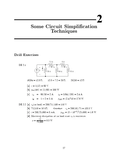
2Some Circuit Simpli¯cationTechniquesDrill ExercisesDE2.116k64=12:8−;12:8+7:2=20−;20k30=12−[a]v=5(12)=60V[b]p5A(del)=(5)(60)=300W[c]i A=60=30=2A i C=3(64)=(80)=2:4Ai B=5¡2=3A p10−=(2:4)210=57:6WDE2.2[a]v o(no load)=200(75)=100=150V[b]75k150=50k−,therefore v o=200(50)=75=133:3V[c]i=200=25;000=8mA,p25k=(8£10¡3)2(25;000)=1:6W[d]Maximum dissipation at no load since v o is maximump=v2o75;000=0:3W2728CHAPTER2.Some Circuit Simpli¯cation TechniquesDE2.3v30=6+4(0:825)=9:3V;i30=v3030=0:31Ai6=i30+0:825=1:135A;i10=0:825+0:31=1:135A¡v30¡6i b+v20¡10i10=0¢::v20=9:3+16(1:135)=27:46Vi20=27:4620=1:373A;i5=i6+i20=2:508Ai30=0:31A;i6=1:135A;i10=1:135A;i20=1:373A;and i5=2:508ADE2.4Problems29i =7212=6A [a]v =7212(8)=48V ;i 120V =120¡57:620=3:12A [b]v a =6(9:6)=57:6V ;p 120V (del)=120i a =374:40WDE 2.5[a]110V source actingalone:R e =10(14)24=356−i 0=1105+35=6=13213Av 0o=µ356¶µ13213¶=77013V 4A source actingalone:5−k 10−=50=15=10=3−10=3+2=16=3−30CHAPTER2.Some Circuit Simpli¯cation Techniques 16=3k12=48=13−Hence our circuit reduces to:It follows thatv00a=4(48=13)=(192=13)Vandv00o=¡v00a(16=3)(10=3)=¡58v00a=¡(120=13)V¢::v o=v0o+v00o=77013¡12013=50V[b]p=v2o10=250WDE2.670-V source acting alone:v0=70¡4i0bi0s=v0b2+v010=i0a+i0b70=20i0a+v0bi0a=70¡v0b 20Problems31¢::i 0b=v 0b 2+v 010¡70¡v 0b 20=1120v 0b +v 010¡3:5v 0=v 0b+2i 0b ¢::v 0b =v 0¡2i 0b¢::i 0b =1120(v 0¡2i 0b )+v 010¡3:5or i 0b =1342v 0¡7042¢::v 0=70¡4µ1342v 0¡7042¶orv 0=322094=161047V 50-V source actingalone:v 00=¡4i 00bv 00=v 00b +2i 00bv 00=¡50+10i 00d ¢::i 00d=v 00+5010i 00s =v 00b 2+v 00+5010i 00b=v 00b 20+i 00s =v 00b 20+v 00b 2+v 00+5010=1120v 00b +v 00+5010v 00b =v 00¡2i 00b¢::i 00b =1120(v 00¡2i 00b )+v 00+5010or i 00b =1342v 00+10042Thus,v 00=¡4µ1342v 00+10042¶orv 00=¡20047V Hence,v =v 0+v 00=161047¡20047=141047=30V32CHAPTER2.Some Circuit Simpli¯cation Techniques ProblemsP2.1[a]p4−=i2s4=(12)24=576W p18−=(4)218=288W p3−=(8)23=192W p6−=(8)26=384W[b]p120V(delivered)=120i s=120(12)=1440W[c]p diss=576+288+192+384=1440WP2.2[a]From Ex.3-1:i1=4A,i2=8A,i s=12Aat node x:¡12+4+8=0,at node y:12¡4¡8=0[b]v1=4i s=48V v3=3i2=24Vv2=18i1=72V v4=6i2=48Vloop abda:¡120+48+72=0;loop bcdb:¡72+24+48=0;loop abcda:¡120+48+24+48=0P2.31R eq=16+110+115=1030=13;R eq=3−v(2+8+5)−=(20)(3)=60V;i(2+8+5)−=60=15=4A P5−=(4)2(5)=80WP2.4[a]R eq=2+2+(1=4+1=5+1=20)¡1=6−i g=120=6=20Av4−=120¡(2+2)20=40Vi o=40=4=10AProblems33 i(15+5)−=40=(15+5)=2Av o=(5)(2)=10V[b]i15−=2A;P15−=(2)2(15)=60W[c]P120V=(120)(20)=2:4kWP2.5[a]R eq=R k R=R22R=R2[b]R eq=R k R k R k¢¢¢k R(n R's)=R kR n¡1=R2=(n¡1)R+R=(n¡1)=R2nR=Rn[c]One solution:700−=200−+500−=1000=5+1000=2=1k−k1k−k1k−k1k−k1k−+1k−k1k−[d]One solution:5:5k−=5k−+0:5k−=2k−+2k−+1k−+0:5k−=2k−+2k−+2k−2+2k−4=2k−+2k−+2k−k2k−+2k−k2k−k2k−k2k−34CHAPTER2.Some Circuit Simpli¯cation TechniquesP2.6[a]12−k24−=8−Therefore,R ab=8+2+6=16−[b]1R eq=124k−+130k−+120k−=15120k−=18k−R eq=8k−;R eq+7=15k−1R ab=115k−+130k−+115k−=530k−=16k−R ab=6k−P2.7[a]For circuit(a)R ab=15k(18+48k16)=10−For circuit(b)1 R e =120+115+120+14+112=3060=12R e=2−R e+16=18−18k18=9−R ab=10+8+9=27−For circuit(c)48k16=12−12+8=20−20k30=12−12+18=30−30k15=10−10+10+20=40−R ab=40k60=24−[b]P a=20210=40WP b=144227=768WP c=62(24)=864WProblems35P2.8[a]5k20=100=25=4−5k20+9k18+10=20−9k18=162=27=6−20k30=600=50=12−R ab=5+12+3=20−[b]5+15=20−30k20=600=50=12−20k60=1200=80=15−3k6=18=9=2−15+10=25−3k6+30k20=2+12=14−25k75=1875=100=18:75−26k14=364=40=9:1−18:75+11:25=30−R ab=2:5+9:1+3:4=15−[c]3+5=8−60k40=2400=100=24−8k12=96=20=4:8−24+6=30−4:8+5:2=10−30k10=300=40=7:5−45+15=60−R ab=1:5+7:5+1:0=10−P2.9[a]R cond=845(0:0397)=33:5465−R total=2(1=2)R cond=33:5465−P loss=(2000)2(33:5465)=134:186MWP calif=800(2)¡134:186=1465:814MWE±ciency=(1465:814=1600)£100=91:61%[b]P calif=2000¡134:86=1865:814MWE±ciency=93:29%[c]P loss=(3000)2¢2¢(1=3)¢845¢(0:0397)=201:279MWP oregon=3000MW;P calif=3000¡201:279=2798:7MWE±ciency=(2798:70=3000)£100=93:29%P2.10i10k=(18)(15)40=6:75mAv15k=¡(6:75)(15)=¡101:25V i3k=18¡6:75=11:25mAv12k=¡(12)(11:25)=¡135Vv o=¡101:25¡(¡135)=33:75V36CHAPTER 2.Some Circuit Simpli¯cation TechniquesP 2.11[a]v 1k =11+5(30)=5V v 15k =1515+60(30)=6Vv x =v 15k ¡v 1k =6¡5=1V [b]v 1k =v s6(1)=v s =6v 15k=v s75(15)=v s =5v x =(v s =5)¡(v s =6)=v s =30P 2.1260k 30=20−i 30−=(25)(75)125=15A v o =(15)(20)=300V v o +30i 30=750V v g ¡12(25)=750v g =1050VP 2.135−k 20−=4−;4−+6−=10−;10k 40=8−;Therefore,i g =1258+2=12:5A i 6−=(40)(12:5)50=10A;i o =(5)(10)25=2A P 2.14[a]40k 10=8−i 75V =7510=7:5A 8+7=15−i 4+3−=7:5µ3045¶=5A15k 30=10−i o =¡5µ1050¶=¡1A[b]i 10−=i 4+3−+i o =5¡1=4AP 10−=(4)2(10)=160WP2.15[a]v9−=(1)(9)=9Vi2−=9=(2+1)=3Ai4−=1+3=4A;v25−=(4)(4)+9=25Vi25−=25=25=1A;i3−=i25−+i9−+i2−=1+1+3=5A;v40−=v25−¡v3−=25¡(¡5)(3)=40Vi40−=40=40=1Ai5k20−=i40−+i25−+i4−=1+1+4=6Av5k20−=(4)(6)=24Vv32−=v40−+v5k20−=40+24=64Vi32−=64=32=2A;i10−=i32−+i5k20−=2+6=8Av g=10(8)+v32−=80+64=144V:[b]P20−=(v5k20−)220=24220=28:8WP2.16[a]Let i s be the current oriented down through the resistors.Then,i s=V sR1+R2+¢¢¢+R k+¢¢¢+R nandv k=R k i s=R kR1+R2+¢¢¢+R k+¢¢¢+R nV s[b]i s=2005+15+30+10+40=2Av1=2(5)=10V v2=2(15)=30V v3=2(30)=60V v4=2(10)=20V v5=2(40)=80VP2.17[a]v o=2525(20)=20V[b]v o=255+R eR eR e=(20)(12)32=7:5k−v o=2512:5(7:5)=15V[c]v o25=2025=0:80[d]v o25=1525=0:60P2.18[a]No load:v o=R2R1+R2V s=¾V s¢::¾=R2R1+R2 Load:v o=R eR1+R eV s=¯V s¢::¯=R eR e+R1R e=R2R LR2+R L¢::¯=R2R LR1R2+R L(R1+R2)But R1+R2=R2¾¢::R1=R2¾¡R2¢::¯=R2R LR2³R2¾¡R2´+R L R2¾¯=R LR 2³1¾¡1´+R L ¾or ¯R 2µ1¾¡1¶+¯R L ¾=R L ¯R 2µ1¾¡1¶=R L Ã1¡¯¾!¢::R 2=(¾¡¯)¯(1¡¾)R LR 1=(1¡¾)¾R 2=þ¡¯¾¯!R L[b]R 1=(0:9¡0:7)0:63(126)k −=40k −R 2=(0:9¡0:7)(0:7)(0:1)(126)k −=360k −P 2.19[a]Let v o be the voltage across the parallel branches,positive at the upperterminal,theni g =v o G 1+v o G 2+¢¢¢+v o G N =v o (G 1+G 2+¢¢¢+G N )It follows thatv o =i g(G 1+G 2+¢¢¢+G N )The current in the k th branch is i k =v o G k ;Thus,i k =i g G k[G 1+G 2+¢+G N ][b]i 6:25=1142(0:16)[4+0:4+1+0:16+0:1+0:05]=32mAP 2.20R e =48£103=500−¢::XG =1500=2mS i 1=2i 2=2(10i 3)=20i 4i 2=10i 3=10i 4i 3=i 48=20i4+10i4+i4+i4=32i4¢::i4=832=0:25mAR4=v gi4=40:25£10¡3=16k−i3=i4=0:25mA ¢::R3=16k−i2=10i4=2:5mAR2=v gi2=42:5£10¡3=1:6k−i1=20i4=5mAR1=v gi1=45£10¡3=800−P2.21[a]i o=120=40k−=3mA[b]v a=(3)(20)=60Vi a=v a100=0:6mAi b=4¡3:6=0:4mAv b=60¡(0:4)(15)=54Vi g=0:4¡54=30=¡1:4mAp75V(developed)=(75)(1:4)=105mWCheck:p4mA(developed)=(60)(4)=240mWX P dev=105+240=345mWX P dis=(¡1:4)2(15)+(1:8)2(30)+(0:4)2(15)+(0:6)2(100)+(3)2(20)=345mWP2.22Apply source transformations to both current sources to geti o=¡66=¡1mAP2.23[a]¢::v o=1(240)=120V;i o=120=24=5A2[b]p300V=¡12:5(300)=¡3750WTherefore,the300V source is developing3.75kW.[c]¡10+i6−+7:5¡12:5=0;¢::i6−=15Av10A+4(10)+6(15)=0;¢::v10A=¡130Vp10A=10v10A=¡1300WTherefore the10A source is developing1300W.[d]X p dev=3750+1300=5050Wp4−=100(4)=400Wp40−=(7:5)2(40)=2250Wp6−=(15)2(6)=1350Wp42−=(5)2(42)=1050WX p diss=400+1350+2250+1050=5050W(CHECKS)P2.24Applying a source transformation to each current source yieldsNow combine the20V and10V sources into a single voltage source and the5−,4−and1−resistors into a single resistor to getNow use a source transformation on each voltage source,thuswhich can be reduced to¢::i o=(1:25)(8)=1A10P2.25First,¯nd the Th¶e venin equivalent with respect to R o.P2.26100−k25−=20−¢::i=400=5A60+20v0o=20i=100V100−k60−=37:5−i=50025+37:5=8Av00o=37:5i=300Vv o=v0o+v00o=100+300=400V P2.27i0o=10025=4A15−k30−=10−i00o=¡5025=¡2A¢::i o=i0o+i00o=4¡2=2A P2.2815=2i0¢+50i1+3i0¢Problems4715=2i 0¢+12i 02i 0¢=i 01+i 02;i 01=27=26A;i 0¢=51=26A¢::i 02=1213A;v 0o=9613V ¡2i 00¢=5i 001+3i 00¢¢::i 00¢=¡i 001i 002=i 00¢¡i 001=2i 00¢4i 002+(8+i 002)8=¡2i 00¢¢::i 002=¡6413A;i 001=3213A;i 00¢=¡3213A ¢::8+i 002=4013A ¢::v 00o=8µ4013¶=32013V ¢::v o =v 0o +v 00o =9613+32013=32V48CHAPTER2.Some Circuit Simpli¯cation TechniquesP2.29[a]The evolution of the circuit shown in Fig.P2.29is illustrated in the following steps:[b]Starting at the left end of the circuit and working toward the right end,aseries of source transformations yields:Problems49V R=4 4R (2R)=V R8P2.30[a]The evolution of the circuit in Fig.P2.30can be shown in two steps,thus:[b]Moving from left to right,a series of source transformations yields:50CHAPTER2.Some Circuit Simpli¯cation Techniquesv o=V R=84R(2R)=V R16Problems51 P2.31Eq.(2.34)v o=12V R(Switch1)Eq.(2.35)v o=14V R(Switch2)Eq.(2.36)v o=18V R(Switch3)Eq.(2.37)v o=116V R(Switch4)Given V R=16V:Switch Position v o12340000v o=0V000V R v o=116V R=1V00V R0v o=18V R=2V00V R V R v o=116V R+18V R=3V0V R00v o=14V R=4V0V R0V R v o=14V R+116V R=5V0V R V R0v o=14V R+18V R=6V0V R V R V R v o=14V R+18V R+116V R=7VV R000v o=12V R=8VV R00V R v o=12V R+116V R=9VV R0V R0v o=12V R+18V R=10VV R0V R V R v o=12V R+18V R+116V R=11VV R V R00v o=12V R+14V R=12VV R V R0V R v o=12V R+14V R+116V R=13VV R V R V R0v o=12V R+14V R+18V R=14VV R V R V R V R v o=12V R+14V R+18V R+116V R=15V52CHAPTER2.Some Circuit Simpli¯cation TechniquesThis page intentionally left blank。
电路分析师作文英语Title: The Role and Responsibilities of a Circuit Analyst。
Introduction:Circuit analysis is a crucial aspect of electrical engineering, playing a vital role in ensuring the functionality, efficiency, and safety of electronic systems. As a circuit analyst, one undertakes the responsibility of scrutinizing, designing, and optimizing circuits to meet specific requirements. In this essay, we delve into therole and responsibilities of a circuit analyst,highlighting the skills and knowledge required to excel in this field.Understanding Circuit Analysis:Circuit analysis involves the examination of electrical circuits to understand their behavior and performance. Itencompasses various techniques and methodologies to analyze voltage, current, power, and other electrical parameters within a circuit. A circuit analyst employs mathematical models, simulation software, and testing equipment to assess circuit performance accurately.Responsibilities of a Circuit Analyst:1. Circuit Design:One of the primary responsibilities of a circuit analyst is to design electrical circuits that meet predetermined specifications. This involves understanding the functional requirements of the circuit, selecting appropriate components, and arranging them to achieve the desired outcome. Circuit analysts must possess a deep understanding of circuit theory, semiconductor devices, and analog/digital electronics to create effective designs.2. Simulation and Analysis:Circuit analysts utilize simulation software such asSPICE (Simulation Program with Integrated Circuit Emphasis) to model and analyze circuit behavior. Through simulation, analysts can predict how a circuit will perform under different operating conditions, identify potential issues, and optimize circuit parameters for improved performance. Proficiency in simulation tools is essential for accurately assessing circuit behavior and making informed design decisions.3. Troubleshooting and Debugging:When confronted with malfunctioning circuits or unexpected behavior, circuit analysts must possess strong troubleshooting skills to identify and rectify faults. This involves systematic analysis of circuit components, signal waveforms, and electrical parameters to isolate the root cause of the problem. Effective troubleshooting requires a combination of theoretical knowledge, practical experience, and attention to detail.4. Performance Optimization:Circuit analysts are responsible for optimizing circuit performance in terms of efficiency, reliability, and cost-effectiveness. This may involve refining circuit parameters, selecting alternative components, or redesigning circuitry to achieve desired performance metrics. Optimization efforts aim to enhance circuit functionality while minimizing resource utilization and mitigating potential risks.5. Compliance and Standards:Ensuring compliance with industry standards, regulations, and safety protocols is a critical aspect of the circuit analyst's role. Analysts must stay abreast of relevant standards such as IEEE, IEC, and NEC to ensurethat their designs meet legal and safety requirements. Adherence to standards not only ensures the reliability and integrity of circuits but also fosters trust among stakeholders.Skills and Qualifications:To excel as a circuit analyst, individuals should possess a combination of technical expertise, problem-solving abilities, and communication skills. Some essential skills and qualifications include:Proficiency in circuit theory, semiconductor physics, and analog/digital electronics.Experience with simulation software and circuit analysis tools.Strong analytical and critical thinking skills.Effective communication and teamwork abilities.Attention to detail and a methodical approach to problem-solving.Knowledge of industry standards and regulatory requirements.Conclusion:In conclusion, the role of a circuit analyst is multifaceted, encompassing design, analysis, optimization, and troubleshooting of electrical circuits. By leveraging their technical expertise and problem-solving skills, circuit analysts play a pivotal role in the development of reliable and efficient electronic systems. With the continuous evolution of technology, the demand for skilled circuit analysts remains high, making it an exciting and rewarding career path for aspiring electrical engineers.。
电路基础英文版精编版第六版课程设计1. IntroductionElectricity is an essential component of modern life, powering homes, businesses, and industries around the globe. Understanding the basics of electric circuits is therefore a critical skill for anyone interested in pursuing a career in the electrical or electronics fields. The Circuits Fundamentals course is designed to provide students with an in-depth understanding of electric circuits.This document outlines a course design for the sixth edition of the Electric Circuits Fundamentals textbook, a well-known and widely-used resource for undergraduate students studying electrical and electronics engineering.2. Course ObjectivesThe primary objective of this course is to provide students with a comprehensive understanding of the fundamental principles of electric circuits. By the end of the course, learners will be able to:•Design, analyze, and interpret electric circuits using standard tools and techniques.•Understand the physical principles that underpin electric circuits, and how these principles relate toreal-world applications.•Effectively communicate their understanding of electric circuits to others, both in written and oralformats.3. Course OutlineThe Circuits Fundamentals course comprises 14 chapters, covering a wide range of topics related to electric circuits. The following table provides an overview of the course structure:Chapter Topic Learning Objectives1 Basic Concepts To introduce the fundamentalconcepts of electric circuits2 Resistance andOhm’s Law To understand the resistance and its relationship with Ohm’s Law3 Energy and Power inCircuits Get to know energy concepts and power dissipation in circuits4 Series Circuits Understand the properties andanalyze the behavior of seriescircuits5 Parallel Circuits Understand the properties andanalyze the behavior of parallelcircuits6 Series-ParallelCircuits Understand the properties and analyze the behavior of series-parallel circuits7 Circuits withCapacitors Get to know the properties and behavior of circuits with capacitors8 Circuits withInductors Get to know the properties and behavior of circuits with inductors9 Circuits withCapacitors andInductors Understand the behavior of circuits with capacitors and inductors10 Frequency Response Understand the frequency and itsresponse in circuit elements11 AC Power Understand the properties ofalternating current power12 Three-PhaseCircuits Understand the principles and usage of three-phase circuits13 Transformers Understand the behavior andprinciples of transformers14 Circuit Analysisusing SPICESoftware Understand the usage and implementation of SPICE software4. Course Materials4.1 Required TextbookThe required textbook for this course is the sixth edition of the Electric Circuits Fundamentals textbook. This resource provides a comprehensive overview of the topics covered in the course and includes a range of helpful examples, exercises, and review questions to support learning.4.2 Required HardwareStudents will also need access to the following hardware: • A computer or laptop with appropriate software for circuit simulation, such as the SPICE software.•Basic tools for building and testing circuits, including multimeters, signal generators, andoscilloscopes.5. Course AssessmentStudent learning in this course will be assessed through a combination of homework assignments, quizzes, and exams.Homework assignments will be given regularly to reinforce key concepts introduced in each chapter. Quizzes will be given throughout the course to assess student understanding of specific topics, while exams will be given at the end of the course to evaluate overall knowledge and understanding.6. ConclusionThe Circuits Fundamentals course provides students with a comprehensive understanding of electric circuits and their applications. By completing this course, learners will develop a deep understanding of the fundamental principles of electric circuits, as well as the ability to apply this knowledge to real-world situations.。

Chapter 9 Sinusoids and PhasorsSinusoidsA sinusoid is a signal that has the form of the sine or cosine function.anglephase um ent t frequencyangular am plitudeVm where t V v m ==+==+=φφϖϖφϖarg )cos()cos(φϖ+=t V v m φωtfTππω22==radians/second (rad/s)f is in hertz(Hz))cos()()cos()(222111φωφω+=+=t V t v t V t v m m Phase difference:φθφθθθφφφωφωθby v lags v by v leads v phase in are v and v phaseof out are v and v if t t 210210210210)()(2121<>=≠-=+-+=Complex Numberforml exponentia form sinusoidal formpolar form r rectangula φφφφj rez jrsin rcos z r z jy x z =+=∠=+=φPhasora phasor is a complex number representing the amplitude and phase angle of a sinusoidal voltage or current.Eq.(8-1)and Eq. (8-2) Eq.(8-3)When Eq.(8-2) is applied to the general sinusoid we obtainE q.(8-4)The phasor V is written asEq.(8-5)Fig. 8-1 shows a graphical representation commonly calleda phasor diagram.Fig. 8-1: Phasor diagram Two features of the phasor concept need emphasis:1.Phasors are written in boldfacetype like V or I1 to distinguishthem from signal waveformssuch as v(t)and i1(t).2. A phasor is determined byamplitude and phase angle anddoes not contain anyinformation about the frequencyof the sinusoid.In summary, given a sinusoidal signal , the corresponding phasor representation is . Conversely, given the phasor , the corresponding sinusoid is found by multiplying the phasor by and reversing the steps in Eq.(8-4) as follows:E q.(8-6))cos()(φϖ+=t V t v m φ∠=Vm V Time domainrepresentationPhase-domain representationProperties of Phasors•additive propertyEq.(8-7)Eq.(8-8)Eq.(8-9)•derivative propertyEq.(8-10)Vj dtdv ω⇔∴Time domain representationPhase-domain representation•Integral propertyTime domain representationPhase-domainrepresentation⎰⇔ωj Vvdt The differences between v(t) and V:V(t) is the instantaneous or time-domain representation, while V is the frequency or phasor-domain representation.2.V(t) is a real signal which is time dependent, while V is just a supposed value to simplify the analysisThe complex exponential is sometimes called a rotating phasor, and the phasor V is viewed as a snapshot of the situation at t=0.Fig. 8-2: Complex exponential+ j + real-real-j ωtV mθ= 0θ= 90 or π/2θ= -90 or -π/2θ= 180 or π151050510151513.51210.597.564.531.5010V r ms ac signal at 0.5 Hzvoltage in voltsa n g u l a r f r e q u e n c y t i m e s t i m e i n r a d i a n s12.566-ω-t n⋅14.14214.142-v rea l t ()n5101515129630369121510V rms ac signal at 0.5 Hzangular frequency times time in radiansV o l t a g e i n v o l t s14.14214.142-v im a g t n ()12.5660ωt ⋅()n)sin(is axis )(imaginary j on the phasor rotating the of projection The t V v m ima g ω⋅=)cos(is axis real on the phasor rotating the of projection The t V v m rea l ω⋅=()()caseparticular In this 5.02cos 102cos t t f V v m ⋅⋅=⋅⋅=ππEXAMPLE 8-1(a)Construct the phasors for the following signals:(b) Use the additive property of phasors and the phasorsfound in (a) to find v(t)=v1(t)+v2(t).SOLUTION(a) The phasor representations of v(t)=v1(t)+ v2(t) are(b) The two sinusoids have the same frequent so the additive property of phasors can be used to obtain their sum:The waveform corresponding to this phasor sum isV1V21jVEXAMPLE 8-2(a)Construct the phasors representing the following signals:(b) Use the additive property of phasors and the phasors foundin (a) to find the sum of these waveforms.SOLUTION:(a) The phasor representation of the three sinusoidal currents are(b) The currents have the same frequency, so the additive property of phasors applies. The phasor representing the sum of these current isFig. 8-4EXAMPLE 8-3Use the derivative property of phasors to find the time derivative of v(t)=15cos(200t-30°).The phasor for the sinusoid is V=15∠-30 °.According tothe derivative property, the phasor representing the dv/dt isfound by multiplying V by jω.SOLUTION:The sinusoid corresponding to the phasor jωV isDevice Constraints in Phasor FormV oltage-current relations for a resistor in the: (a) time domain, (b) frequency domain.Resistor:RejImI VIV m m RI Vφφ==Device Constraints in Phasor FormInductor:V oltage-current relations for an inductor in the: (a) time domain, (b) frequency domain.ω︒+==90I V mm LI V φφωDevice Constraints in Phasor Form Capacitor:ωV oltage-current relations for a capacitor in the: (a) time domain, (b) frequency domain.︒+==90VImmCVIφφωConnection Constraints in Phasor Form KVL in time domainKirchhoff's laws in phasor form (in frequency domain)KVL: The algebraic sum of phasor voltages around a loop iszero.KCL: The algebraic sum of phasor currents at a node is zero.The IV constraints are all of the formV=ZI or Z= V/IEq.(8-16)where Z is called the impedance of the elementThe impedance Z of a circuit is the ratio of the phasor voltage V to the phasor current I, measured in ohms(Ω)reactance. the is Z Im X and resistance the is Z Re R where ==+=jXR Z The impedance is inductive when X is positiveis capacitive when X is negativeθθθθsin,cos tan, where 122Z X Z R and RXX R Z Z Z ===+=∠=-EXAMPLE 8-5Fig. 8-5The circuit in Fig. 8-5 is operating in the sinusoidal steady state with and . Find the impedance of the elements in the rectangular box.SOLUTION:︒VI0.278/R=37.9-∠=3L2The Admittance ConceptThe admittance Y is the reciprocal of impedance, measured in siemens (S)VI Z Y ==1Y=G+jBWhere G=Re Y is called conductance and B=Im Y is called the susceptance 2222,1XR XB X R R G jX R jB G +-=+=+=+How get Y=G+jB from Z=R+jX ?Cj Y capacitor Lj Y inductor GR Y resistor C L R ωω====:1:1:Basic Circuit Analysis with PhasorsStep 1: The circuit is transformed intothe phasor domain by representing theinput and response sinusoids as phasorand the passive circuit elements bytheir impedances.Step 2: Standard algebraic circuittechniques are applied to solve thephasor domain circuit for the desiredunknown phasor responses.Step 3: The phasor responses areinverse transformed back into time-domain sinusoids to obtain theresponse waveforms.Series Equivalence And Voltage Divisionwhere R is the real part and X is the imaginary partEXAMPLE 8-6Fig. 8-8The circuit in Fig. 8 -8 is operating in the sinusoidal steady state with(a) Transform the circuit into the phasor domain.(b) Solve for the phasor current I.(c) Solve for the phasor voltage across each element.(d) Construct the waveforms corresponding to the phasors found in (b) and (c)SOLUTION:PARALLEL EQUIVALENCE AND CURRENT DIVISIONRest ofthecircuitY1Y1Y2Y NIVI1I2I3 phasor version of the current division principleEXAMPLE 8-9Fig. 8-13The circuit in Fig. 8-13 is operating in the sinusoidal steady state with i S(t)=50cos2000t mA.(a) Transform the circuit into the phasor domain.(b) Solve for the phasor voltage V.(c) Solve for the phasor current through each element.(d) Construct the waveforms corresponding to the phasors found in (b) and (c).SOLUTION:(a) The phasor representing the input source current isIs=0.05∠0°A. The impedances of the three passive elements areFig. 8-14And the voltage across the parallel circuit isThe sinusoidal steady-state waveforms corresponding to thephasors in (b) and (c) areThe current through each parallel branch isEXAMPLE 8-10Fig. 8-15Find the steady-state currents i(t), and i C(t)in the circuit of Fig. 8-15 (for Vs=100cos2000t V, L=250mH, C=0.5 μF, and R=3kΩ).SOLUTION:Vs=100∠0°Y←→△TRANSFORMATIONSThe equations for the △to Ytransformation areThe equations for a Y-to-△transformation arewhen Z1=Z2=Z3=Z Y or Z A=Z B=Z C=Z N.Z Y=Z N/3 and Z N=3Z Y balanced conditionsEXAMPLE 8-12Use a △to Y transformation to solve for the phasor current I X in Fig. 8-18.Fig. 8-18SOLUTION:ABC△to Y。

IntroductionCircuit analysis is the process of solving mathematical equations in order to determine how electric current flows in a circuit. It is an essential skill for anyone interested in electronic design, as it allows us to predict the performance of a circuit before it is built, saving time and resources. In this document, we will be discussing the foundational principles of circuit analysis and circuits in general, in the context of an English-language course.ObjectivesThe objectives of this course are to:•Learn the fundamental principles of circuits, including voltage, current, resistance, and power•Understand how to apply Ohm’s law and Kirchhoff’s laws to analyze simple circuits•Gn familiarity with circuit elements such as resistors, capacitors, and inductors, and how they affect circuit behavior •Explore more complex circuits, including those contning voltage and current sources and those with multiple loops andnodes•Learn how to use simulation software to predict circuit performance.TopicsUnit 1: Introduction to Circuits•Definition of a circuit: series and parallel circuits.•Basic circuit elements: voltage sources, resistors, capacitors, and inductors.•Voltage, current, resistance, and power: Ohm’s law and its application.Unit 2: Circuit Analysis Techniques•Kirchhoff’s voltage law and Kirchhoff’s current law.•Circuit analysis using nodal and mesh analysis.•Superposition principle and Thevenin’s theorem.Unit 3: Capacitors and Inductors•Capacitors: capacitance, charge, voltage, current, and energy storage.•Inductors: inductance, magnetic field, voltage, current, and energy storage.•Series and parallel combination of capacitors and inductors. Unit 4: AC Circuits•AC voltage and current: peak, root mean square, and average values.•Sinusoidal waveforms: equations, phasors, and frequency domn analysis.•AC circuits contning resistors, capacitors, and inductors: impedance, admittance, and phase angle.Unit 5: More Complex Circuits•Voltage and current sources: DC and AC sources, independent and dependent sources.•Circuit analysis with multiple loops and nodes: nodal and mesh analysis.•Maximum power transfer theorem and impedance matching.Unit 6: Circuit Simulation•Introduction to simulation software: Circuit Simulator, LTSpice, and MATLAB.•Simulation of basic and intermediate circuits.•Circuit simulation using MATLAB live scripts.AssessmentThe course will be assessed through a combination of in-class participation, homework assignments, and exams. Homework problems willbe assigned regularly and graded for accuracy and completeness. Examswill cover the material discussed in class and in the homework assignments. In-class participation will be assessed based on attendance, active participation in class discussions, and engagement with class material.ConclusionThis course provides a foundation in circuit analysis that is essential for anyone interested in electronic design. By emphasizing the fundamental principles of circuits and the methods used to analyze them,students will gn a deeper understanding of circuit behavior and be better equipped to design and troubleshoot electronic circuits.。

Circuit Analysis Basics Teaching Design (EN Version) BackgroundCircuit analysis is a fundamental topic in electrical engineering.It is important for students to understand the principles and techniques of circuit analysis in order to solve more complex problems inelectrical and electronic systems.English proficiency has become a crucial skill in many fields, including engineering. In order to provide high-quality education to international students and enhance their English language skills, it is necessary to design a curriculum that incorporates both circuit analysis basics and English language learning.mThe m of this teaching design is to provide a comprehensive introduction to circuit analysis basics in English. The course willcover the fundamenta l principles of circuit analysis, including Ohm’s Law, Kirchhoff’s Laws, and nodal and mesh analysis. Additionally, this course will m to improve students’ English language skills in technical communication, such as reading and writing circuit diagrams and conducting group discussions.Learning Outcomes•Understand the fundamental principles of circuit analysis and their applications.•Develop proficiency in technical communication using English.•Analyze simple circuits using Ohm’s law and Kirchhoff’s laws.•Apply nodal and mesh analysis to solve complex circuits.•Design and analyze basic circuits using a breadboard. SyllabusModule 1: Introduction to Circuit Analysis•Overview of electrical circuits•Current, voltage, and power•Passive and active components•Circuit diagrams and symbols•Introduction to circuit analysis basicsModule 2: Ohm’s Law and Kirchhoff’s Laws•Resistive circuits•Ohm’s Law and its applications•Kirchhoff’s Voltage Law (KVL) and Kirchhoff’s Current Law (KCL)•Series and parallel circuits•Voltage and current divisionModule 3: Nodal and Mesh Analysis•Nodal analysis and its applications•Mesh analysis and its applications•Superposition principle and its applications•Source transformationModule 4: Breadboarding and Circuit Design•Breadboarding basics•Designing circuits using a breadboard•Analyzing and testing breadboarded circuits•Introduction to circuit simulation softwareModule 5: Technical Communication in Circuit Analysis•Terminology and vocabulary in circuit analysis•Reading and writing circuit diagrams in English•Conducting successful group discussions•Preparing and presenting technical reports and presentations AssessmentThe course will be assessed using a variety of methods, including written assignments, quizzes, laboratory reports, and presentations. Students will also be required to complete a final project, in which they will design and analyze a basic circuit using a breadboard.ConclusionThis teaching design provides a comprehensive introduction tocircuit analysis basics in English. By incorporating technical communication skills and practical hands-on experience, students will gn a deeper understanding of circuit analysis principles and techniques, as well as improved English language skills.。

电路分析基础英文版教学设计IntroductionCircuit analysis is the foundation of electrical and electronics engineering. A basic understanding of circuit analysis is essential for any electrical or electronics engineer. This document outlines a syllabus for teaching circuit analysis to students who are fluent in English.Course ObjectivesBy the end of this course, students are expected to be able to:1.Understand the basic concepts of circuit analysis2.Analyze DC circuits3.Analyze AC circuits4.Analyze circuits with energy storage elements such ascapacitors and inductors5.Understand circuit theorems such as ohm’s law, Kirchoff’slaws, Norton’s theorem, and Thevenin’s theorem6.Analyze circuits with multiple energy sourcesCourse OutlineModule 1: Introduction and Basic Concepts•Introduction to circuit analysis•Electric circuits and their elements•Conductors and insulators•Current, voltage, and power•Passive and active elements•Sources and loadsModule 2: Ohm’s Law•Ohm’s Law•Resistors in series and parallel•Voltage and current division•Kirchoff’s voltage and current lawsModule 3: Circuit Analysis Techniques•Nodal analysis•Mesh analysis•Source transformation•Superposition theorem•Thevenin’s and Norton’s theoremsModule 4: Capacitors and Inductors•Capacitors and their behavior•Inductors and their behavior•Transient analysis of circuits with capacitors and inductors Module 5: AC Circuits•Sinusoidal functions•Phasor representation•Impedance and admittance•AC circuit analysis•Power in AC circuitsModule 6: Multiple Energy Sources•AC and DC sources in the same circuit•Independent and dependent sources•Thevenin and Norton equivalent circuits•Maximum power transfer theoremModule 7: Frequency Response•Resonance in series and parallel circuits•Filters•Bode plotsTeaching MethodologyThe course will be taught using the following methods:LecturesThe lectures will cover the theoretical concepts of circuit analysis. Students will be expected to take notes and ask questions.Problem Solving SessionsIn the problem-solving sessions, students will apply the concepts learned in the lectures to solve problems. Examples will be provided,and students will be expected to solve similar problems.Laboratory SessionsIn the laboratory sessions, students will learn how to useelectrical instruments and carry out experiments. The experiments will illustrate the concepts learned in the lectures.AssessmentThe course assessment will be based on the following:•Two written assignments• A mid-term examination• A final examination•Laboratory reportsConclusionCircuit analysis is essential for electrical and electronics engineering. This syllabus provides a comprehensive outline for teaching circuit analysis to students who are fluent in English. The course will be taught using lectures, problem-solving sessions, and laboratory sessions, with assessments based on written assignments, midterm and final exams, and laboratory reports.。
《电路分析基础》(英文版)((美)尼尔森(Nilsson,J.W.)等著)◆内容简介本书由浅入深、系统全面地讲解了电子电路及电子系统的基本元件、基本概念、基本分析理论和计算方法,主要内容包括电路基本元件、简单电阻电路分析、电路常见分析法、运算放大器基本应用电路、一阶和二阶电路的分析、正弦稳态分析及其功率计算、平衡三相电路、选频电路及滤波器等。
此外,本书结合多年教学经验和生活中的实际应用,给出了大量例题和习题、详尽的图表资料和丰富的实用电路范例。
本书适合作为电气、电子、计算机与自动化等本科专业电路分析或电路理论课程的双语教材,也可供相关学科的科技人员自学或参考。
◆目录Chapter 1 Circuit Variables and Circuit Elements1.1 Circuit Analysis: an Overview1.2 Voltage, Current, and the Basic Circuit Elements1.3 The Ideal Basic Circuit Element1.4 Power and Energy1.5 Voltage and Current Sources1.6 Electrical Resistance (OHM?s Law)1.7 Kirchhoff?s Laws1.8 Analysis of a Circuit Containing Dependent SourcesChapter 2 Some Circuit Simplification Techniques2.1 Source Transformations2.2 SuperpositionChapter 3 Techniques of Circuit Analysis3.1 Terminology3.2 Introduction to the Node-Voltage Method3.3 The Node-Voltage Method and Dependent Sources3.4 The Node-Voltage Method: Some Special Cases3.5 Introduction to the Mesh-Current Method3.6 The Mesh-Current Method and Dependent Sources3.7 The Mesh-Current Method: Some Special Cases3.8 The Node-Voltage Method Versus the Mesh-Current Method3.9 Th?venin and Norton Equivalents3.10 More on Deriving a Th?venin Equivalent3.11 Maximum Power TransferChapter 4 The Operational Amplifier4.1 Operational Amplifier Terminals4.2 Terminal Voltages and Currents4.3 The Inverting-Amplifier Circuit4.4 The Summing-Amplifier Circuit4.5 The Noninverting-Amplifier Circuit4.6 The Difference-Amplifier Circuit4.7 The ComparatorChapter 5 The Natural and Step Response of RL and RC Circuits5.1 The Inductor5.2 The Capacitor5.3 Series-Parallel Combinations of Inductance and Capacitance5.4 Natural Response of RL and RC Circuits5.5 Step Response of RL and RC Circuits5.6 The Integrating AmplifierChapter 6 Natural and Step Responses of RLC Circuits6.1 Introduction to the Natural Response of a Parallel RLC Circuit 6.2 The Forms of the Natural Response of a Parallel RLC Circuit 6.3 The Step Response of a Parallel RLC Circuit6.4 The Natural and Step Response of a Series RLC CircuitChapter 7 Sinusoidal Steady-State Analysis7.1 The Sinusoidal Source7.2 The Sinusoidal Response7.3 The Phasor7.4 The Passive Circuit Elements in the Frequency Domain7.5 Kirchhoff?s Laws in the Frequency Domain7.6 Circuit Simplifications7.7 The Node-Voltage Method7.8 The Mesh-Current Method7.9 Instantaneous, Average, and Reactive Power7.10 The rms Value and Power Calculations7.11 Complex Power and Power CalculationsChapter 8 Balanced Three-Phase Circuits8.1 Balanced Three-Phase Voltages8.2 Three-Phase Voltage Sources8.3 Analysis of the Wye-Wye Circuit8.4 Analysis of the Wye-Delta Circuit8.5 Power Calculations in Balanced Three-Phase Circuits8.6 Measuring Average Power in Three-Phase CircuitsChapter 9 Introduction to Frequency Selective Circuits9.1 Some Preliminaries9.2 Low-Pass Filters9.3 High-Pass Filters9.4 Bandpass Filters9.5 Bandreject Filters。
Linear Circuit Analysis Basics Second Edition CourseDesign (English Version)IntroductionLinear circuit analysis is an important part of electrical engineering, and it is critical for anyone who wishes to design and develop electrical systems. The purpose of this course is to provide students with a thorough understanding of linear circuit analysis andthe mathematics necessary to apply the concepts learned to practicalreal-world systems.In this second edition of the course, we will expand on the material from the first edition and provide more in-depth analysis of linear circuits. Additional topics covered in this course include operational amplifiers, frequency response, and advanced circuit analysis techniques.Course ObjectivesThe objectives of this course are as follows:1.To provide students with a strong understanding of linearcircuit analysis, including the mathematics necessary to apply the concepts learned.2.To teach students how to use operational amplifiers incircuit design and analysis.3.To introduce students to the concept of frequency responseand its importance in circuit analysis.4.To provide students with advanced circuit analysistechniques and problem-solving skills.Course OutlineUnit 1: Review of Linear Circuit AnalysisIn this unit, we will review the concepts from the first edition of the course, including:•Voltage, current, and power in resistance, capacitance, and inductance circuits•Kirchhoff’s laws•Mesh and nodal analysisUnit 2: Operational AmplifiersIn this unit, we will introduce the concept of operational amplifiers, including:•Ideal operational amplifier characteristics•Different configurations of operational amplifiers•Operational amplifier applications, such as voltage followers and amplifiersUnit 3: Frequency ResponseIn this unit, we will introduce the concept of frequency response and its importance in circuit analysis. Topics covered include: •AC steady-state analysis•Phasors and complex impedance•Frequency response of circuitsUnit 4: Advanced Circuit Analysis TechniquesIn this unit, we will cover advanced circuit analysis techniques, including:•Laplace transforms and their applications in circuit analysis•Two-port networks and their analysis•State-space analysisLearning OutcomesBy the end of the course, students will have achieved the following learning outcomes:•An understanding of linear circuit analysis and its applications in electrical engineering.•An understanding of operational amplifiers and their applications in circuit design.•An understanding of frequency response and its importance in circuit analysis.•The ability to use advanced circuit analysis techniques to solve complex circuit problems.Resources RequiredStudents will require the following resources:•Textbook: Linear Circuit Analysis Basics, Second Edition by John Doe (avlable for purchase online)•Scientific calculator•Computer with MATLAB or equivalent software for circuit analysisAssessmentAssessment for this course will consist of the following:1.Assignments (30%): Students will complete four assignmentsthroughout the semester to reinforce the concepts learned in class.2.Midterm exam (30%): A midterm exam will be held halfwaythrough the semester, covering material from the first half of the course.3.Final exam (40%): A final exam will be held at the end ofthe semester, covering all material from the entire course.ConclusionThis second edition of Linear Circuit Analysis Basics is designed to provide students with a thorough understanding of linear circuitanalysis and the mathematics necessary to apply the concepts learned to practical real-world systems. By the end of the course, students will have the skills and knowledge necessary to design and develop electrical systems and solve complex circuit problems.。
英文原文:Circuit analysis with MATLABThe electrical appliances is becoming more and more important in today’s world where computer technology, internet technology and communication technology are developing rapidly and people’s life has been greatly improved.Circuit analysis is a necessary course and basic knowledge for electronic special student. It is the foundation of circuit maintenance and circuit application. As one of the most important subjects for an under-graduated student who’s mayor in electronic information engineering, circuit analysis state for the professional capability. With the development of the circuit analysis field, circuits get more complicated and simulation technology using computer grown up. Dynamic circuit analysis is the most difficult, which takes time and a huge mount of manual work especially when circuit is complicated. So we uses the Matlab/Simulink simulation tools and the power system block model library to make analysis on several simple circuit such as the alternating urgent steady-state circuit、direct current steady-state circuit and first-order dynamic circuit. The circuits are programmed by Matlab language and simulate it by Simulink tools. Although simulation by computer software can not replace the traditional way, it helps people to understand circuit analysis directly and effectively. By these tools,people can demonstrate the circuit performances and reduce complicated calculation. It makes us save a lot of work. During this process,we know how Matlab/Simulink work and show the advantage of Matlab/Simulink tools on circuit analysis,it turns out to be simple,convenience,efficient and flexible.MATLAB is a high-performance language for technical computing. It integrates computation, visualization, and programming in an easy-to-use environment where problems and solutions are expressed in familiar mathematical notation. Typical uses include:1.Math and computation2.Algorithm development3.Modeling, simulation, and prototyping4.Data analysis, exploration, and visualization5.Scientific and engineering graphics6.Application development, including graphical user interface buildingMATLAB is an interactive system whose basic data element is an array that does not require dimensioning. That allows you to solve many technical computing problems, especially those with matrix and vector formations in a fraction of the time, which would take a lot of time to write a program in a scalar non-interactive language such as C or FORTRAN.The name MATLAB stands for matrix laboratory. MATLAB was originally written to provide easy access to matrix software developed by the LINPACK and EISPACK projects. Today, MATLAB engines incorporate the LAPACK and BLAS libraries, embedding the state of the art in software for matrix computation.MATLAB has evolved over a period of years with input many users. In university environments, it is the standard instructional tool for introductory and advancedcourses in mathematics, engineering, and science. In industry, MATLAB is the tool of choice for high-productivity research, development, and analysis.MATLAB features a family of add-on application-specific solutions called toolboxes. Very important to most users of MATLAB, toolboxes allow you to learn and apply specialized technology. Toolboxes are comprehensive collections of MATLAB functions (M-files) that extend the MATLAB environment to solve particular classes of problem. Areas in which toolboxes are available include signal processing, control systems, neural networks, fuzzy logic, wavelets, simulat ion, and many others.The MATLAB system consists of five main parts:Development environment. This is the set of tools and facilities that help you use MATLAB functions and files. Many of these tools are graphical user interfaces. It includes the MATLAB desktop and Command Windows, a command history, an editor and debugger, and browsers for viewing help, the workspaces, files, and the search path.The MATLAB Mathematical Function Library. This is a vast collection of computational algorithms ranging from elementary functions like sum, sine, cosine, and complex arithmetic, to more sophisticated functions like matrix eigenvalue, Bessel functions, and fast Fourier transforms.The MATLAB Language. This is a high-level matrix/array language with control flow statements, functions, data structures, input/output, and object-oriented programming features. It allows both “programming in the small” rapidly create quick and dirty throw-away programs, and “programming in the large” to create complete large and complex application programs.Graphics. MATLAB has extensive facilities for displaying vectors and matrices as graphs, as well as annotating and printing these graphs. It includes high-level functions for two-dimensional and three-dimensional data visualization, image processing, animation, and presentation graphics. It also includes low-level functions that allow you to fully customize the appearance of graphics as well as build complete graphical user interfaces on your MATLAB applications.The MATLAB Application Program Interface(API). This is a library that allows you to write C and FORTRAN programs that interact with MATLAB. It include facilities for calling routines from MATLAB(dynamic linking), calling MATLAB as a computational engine, and for reading and writing MAT-files.In the circuit analysis the RLC two steps electric circuits analysis process is quite complex, and must make the response curve analysis system the performance index extremely to be also difficult. Moreover to the second-order differential equation solution also is quite troublesome, therefore causes the majority the schoolmate which studies this class when studies two steps electric circuits understands quite difficultly. But MATLAB is visible face science and engineering calculation large-scale outstanding science and technology application software, its sentence succinct, the function formidable, simple is practical, in the circuit analysis, the computation has the widespread application. MATLAB provides massive and the rich built-in function, the highly effective succinct sentence, can meet each kind of needs which the electric circuit calculates, the MATLAB language permission plural number directparticipation operation, has satisfied the alternating-current circuit analysis, the computation demand. The MATLAB language may directly draw up the voltage, the electric current measures the chart, but measures the chart analyzes the alternating-current circuit essential important tool, is other computation language strength can not.MATLAB 与电路分析在当今世界,计算机技术,网络技术和通信技术正在迅猛的发展,人民的生活水平逐步提高,电子产品变得越来越重要。