光伏组件对地绝缘阻抗
- 格式:pdf
- 大小:474.80 KB
- 文档页数:5
光伏绝缘阻抗SO检测原理光伏(PV)系统作为可再生能源领域的重要组成部分,其安全性和稳定性对于确保持续供电至关重要。
绝缘阻抗是评估PV系统安全性的关键参数之一,而对其进行准确检测则是预防电气故障、保障人员安全和系统可靠运行的基础。
本文将深入探讨光伏绝缘阻抗的检测原理,特别是关于SO(状态监测)技术的应用。
一、光伏绝缘阻抗基础1.绝缘阻抗的定义绝缘阻抗是指在特定条件下,绝缘材料对电流流动的阻碍能力。
在光伏系统中,它通常指的是直流侧和交流侧之间的电气隔离效果。
良好的绝缘阻抗能够防止电流泄漏,从而减少电击风险、设备损坏以及系统停机时间。
2.绝缘阻抗的重要性PV系统的绝缘阻抗降低可能会导致电流泄漏到地或其他非预期路径,这不仅会影响系统的发电效率,还可能引发严重的安全问题。
因此,定期监测绝缘阻抗是维护PV 系统健康状态的关键环节。
二、光伏绝缘阻抗SO检测原理1.SO检测技术概述SO(状态监测)技术是一种实时或定期评估系统状态的方法,旨在提供关于系统健康状况的及时信息。
在光伏绝缘阻抗检测中,SO技术通常涉及对电气参数的连续测量和分析,以检测绝缘性能的任何变化。
2.检测原理(1)直流注入法直流注入法是一种常用的绝缘阻抗检测方法。
其原理是在PV系统的正负极之间注入一个已知的低电平直流电流,并测量由此产生的直流电压。
通过欧姆定律(V=IR),可以计算出绝缘阻抗。
这种方法的好处是对PV系统的正常运行影响较小,但需要注意的是,注入的电流必须足够小,以防止对系统造成干扰或损害。
(2)交流注入法交流注入法与直流注入法类似,不同之处在于它注入的是交流信号。
这种方法可以更准确地模拟实际工作条件下绝缘材料的行为,因为交流信号能够更好地揭示绝缘材料中的电容性和电导性成分。
然而,交流注入法可能需要更复杂的测量设备和更高的成本。
(3)绝缘监测装置(IMD)绝缘监测装置(IMD)是一种专门用于监测PV系统绝缘阻抗的设备。
它通常安装在PV系统的直流侧,能够连续监测正负极对地之间的绝缘阻抗。

光伏逆变器直流对地绝缘阻抗值
直流对地绝缘阻抗值的测定是光伏逆变器质量检测的重要环节之一。
在工厂出厂前和安装后,都需要对逆变器进行直流对地绝缘阻抗值的测试。
通常情况下,这个数值需要满足一定的标准要求,以确保逆变器在运行过程中不会因为绝缘问题而引发安全隐患。
光伏逆变器直流对地绝缘阻抗值的高低直接影响着逆变器的安全性和可靠性。
如果绝缘阻抗值过低,就会增加逆变器出现漏电、短路等故障的风险,甚至可能导致火灾等严重后果。
因此,光伏逆变器制造商和安装商在生产和安装过程中都需要严格控制直流对地绝缘阻抗值,确保其符合相关标准要求。
总之,光伏逆变器直流对地绝缘阻抗值是光伏系统中一个至关重要的参数,它直接关系到逆变器的安全性和稳定性。
在光伏系统的设计、生产和安装过程中,都需要严格控制和测试这个数值,以确保光伏逆变器的安全可靠运行。
![光伏电池板对地绝缘阻抗检测方法和检测电路[发明专利]](https://img.taocdn.com/s1/m/3a00a88f7e21af45b207a82a.png)
专利名称:光伏电池板对地绝缘阻抗检测方法和检测电路专利类型:发明专利
发明人:俞雁飞,倪华,杨宗军,薛丽英,程千
申请号:CN201610875097.X
申请日:20160930
公开号:CN106452358A
公开日:
20170222
专利内容由知识产权出版社提供
摘要:本申请公开了光伏电池板对地绝缘阻抗检测方法和检测电路,该检测电路的主电路包括电阻R~R和开关S~S,其中:PV经R、R和R接地;PV经R、R和R接地;S一端接R与R的联接点,一端接R与R的联接点;S一端接R与R的联接点,一端接R与R的联接点;相比两开关均断开时,S闭合后R 的等效并联电阻变小、R的等效并联电阻变大,S闭合后则正好相反。
该检测方法包括:若S和S均断开时光伏电池板正负极对地电压之比V/V不小于第一阈值,控制S闭合;若V/V小于第二阈值,控制S闭合;否则,控制S或S闭合。
本申请提高了光伏电池板对地绝缘阻抗检测精度。
申请人:阳光电源股份有限公司
地址:230088 安徽省合肥市高新区习友路1699号
国籍:CN
代理机构:北京集佳知识产权代理有限公司
代理人:王宝筠
更多信息请下载全文后查看。

光伏组串的对地阻抗英文回答:The grounding impedance of a photovoltaic (PV) string refers to the resistance that the string presents to the ground. It is an important parameter to consider in PV system design and installation as it affects the overall performance and safety of the system.The grounding impedance can be influenced by various factors, including the length and gauge of the grounding conductor, the type of soil or ground in which the systemis installed, and the presence of any nearby structures or electrical equipment that may introduce additional impedance.One common method to measure the grounding impedance is the fall-of-potential method, where a known current is passed through the grounding conductor and the voltage drop across the conductor is measured. The grounding impedanceis then calculated using Ohm's law.A low grounding impedance is desirable as it helps to ensure proper fault current dissipation and minimize therisk of electrical shock hazards. It also helps to maintain a stable reference potential for the PV system, reducingthe likelihood of electrical noise or interference.For example, let's say I have a PV system with a long grounding conductor running through a rocky soil. The high resistance of the soil can increase the grounding impedance, potentially leading to higher voltage differences and increased risk of electrical hazards. In this case, I would need to consider using additional grounding electrodes or conductors to reduce the grounding impedance and improvethe safety of the system.中文回答:光伏组串的对地阻抗是指组串对地的电阻。
![一种光伏发电系统对地绝缘阻抗的检测电路以及检测方法[发明专利]](https://img.taocdn.com/s1/m/2df6c95b001ca300a6c30c22590102020740f2a9.png)
(19)中华人民共和国国家知识产权局(12)发明专利申请(10)申请公布号 (43)申请公布日 (21)申请号 201810137513.5(22)申请日 2018.02.10(71)申请人 深圳硕日新能源科技有限公司地址 518000 广东省深圳市宝安区航城街道固戍开发区泰华梧桐工业园13A栋4-5F(72)发明人 吴朋 杨桂贤 郑开科 何述宏 (74)专利代理机构 深圳市道臻知识产权代理有限公司 44360代理人 陈琳(51)Int.Cl.G01R 27/02(2006.01)(54)发明名称一种光伏发电系统对地绝缘阻抗的检测电路以及检测方法(57)摘要本发明涉及检测电路领域,具体涉及一种光伏发电系统对地绝缘阻抗的检测电路,所述检测电路包括分压支路和电压检测单元,所述分压支路包括与电池板正极PV+和地端PE连接的第一支路,以及与电池板负极PV-和地端PE连接的第二支路,所述检测电路还包括与第二支路并联的恒流源支路,所述恒流源支路包括串联设置的恒流源Is和开关;其中,恒流源Is的输入端与第一支路和第二支路的连接端连接,其输出端与第二支路的另一端连接。
通过闭合或者断开开关,输出两组不同的PV对地电压,进而根据基尔霍夫电流定律可得出连接在正极PV+和接地端PE之间的第一电阻R+,以及连接在负极PV-和接地端PE之间的第二电阻R-。
权利要求书1页 说明书3页 附图2页CN 108490258 A 2018.09.04C N 108490258A1.一种电池板对地绝缘阻抗的检测电路,所述检测电路包括分压支路和电压检测单元,所述分压支路包括与电池板正极PV+和地端PE连接的第一支路,以及与电池板负极PV -和地端PE连接的第二支路,所述第一支路和第二支路串联,所述电压检测单元分别获取电池板正极PV+对地端PE的第一电压值V1和电池板负极PV -对地端PE的第二电压值V2,其特征在于:所述检测电路还包括与第二支路并联的恒流源支路,所述恒流源支路包括串联设置的恒流源Is和开关;其中,恒流源Is的输入端与第一支路和第二支路的连接端连接,其输出端与第二支路的另一端连接。
光伏系统发电量低之绝缘阻抗低光伏系统安装之后,用户最关心就是发电量,因为它直接关系到用户的投资回报。
影响发电量的因素很多,组件、逆变、电缆的质量、安装朝向方位角、倾斜角度、灰尘、阴影遮挡、组件和逆变器配比系统方案、线路设计、施工、电网电压等等各种因素都有可能。
本系列文章将根据实际案例一一探讨各种因素。
本文主要讨论绝缘阻抗低对系统的影响。
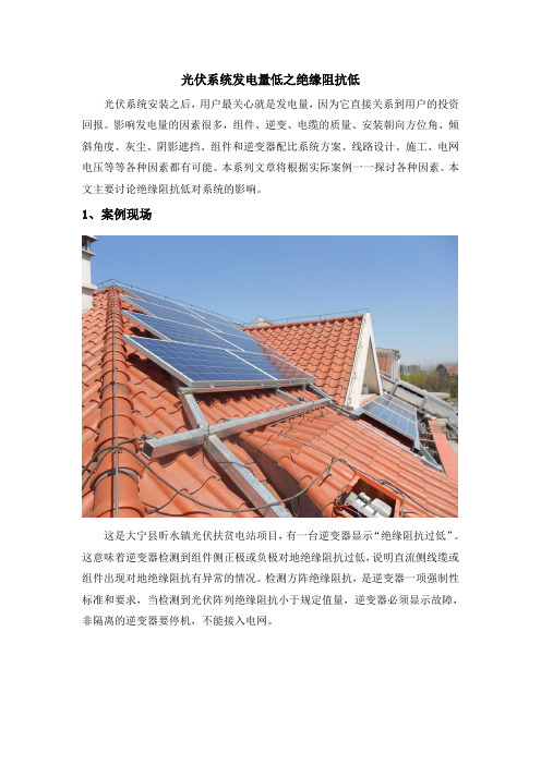
1、案例现场这是大宁县昕水镇光伏扶贫电站项目,有一台逆变器显示“绝缘阻抗过低”。
这意味着逆变器检测到组件侧正极或负极对地绝缘阻抗过低,说明直流侧线缆或组件出现对地绝缘阻抗有异常的情况。
检测方阵绝缘阻抗,是逆变器一项强制性标准和要求,当检测到光伏阵列绝缘阻抗小于规定值量,逆变器必须显示故障,非隔离的逆变器要停机,不能接入电网。
造成局部发热或者电火花,会带来火灾等安全隐患。
3、解决方法对“PV绝缘阻抗过低”,一般可以采用以下处理办法:1)现场检查组件的直流线缆和接地情况首先,出现绝缘阻抗异常的部分的原因是直流线缆破损导致,包括组件之间的线缆,组件至逆变器之间的线缆,特别是墙角的线缆和没有穿管露天铺设的线缆,均需要仔细检查线缆是否有破损情况。
其次,光伏系统没有良好接地,包括组件接地孔未接,组件压块与支架没有良好接触,以及部分支流线缆套管进水,均会导致绝缘阻抗偏低。
2)依靠逆变器逐串排查如果逆变器直流侧为多路接入,可以采用逐一排查的方法对组件进行检测,逆变器直流侧只保留一串组件,开机后查看逆变器是否继续报错,如不继续报错,则说明连接的组件绝缘性能良好,如继续报错,则说明很有可能是该串组件绝缘不符合要求。
或者,譬如,20KW逆变器接入4路,拔出某一路,如果故障报警消失,说明该串有故障。
3)使用摇表或其他专业设备逐串检测现场检查时,用摇表逐串测量组件侧PV+/PV-对地绝缘电阻,阻抗需要大于逆变器绝缘阻抗的阀值要求,在部分项目中,亦可以借用专用的绝缘测量设备。
总结:组件在接入逆变器之前,必须先检测组串对地的绝缘电阻,这是非常必要且不可省略的一个步骤。
光伏方阵绝缘阻抗测试方法1.测试原理:2.测试仪器和材料:-绝缘阻抗测试仪:主要包括测试电源、测试电流和测试电压的测量装置,一般选择数字式绝缘阻抗测试仪。
-测试线缆和接头:用于连接光伏方阵的正负电极和测试仪器。
3.测试步骤:-步骤1:关闭光伏发电系统,确保系统处于停机状态。
-步骤2:检查电路连接是否正确,包括测试仪器和光伏方阵的连接。
-步骤3:设置测试参数,包括测试电压和测试时间。
一般来说,测试电压可选择为1000V,测试时间为1分钟。
-步骤4:打开测试仪器电源,将测量夹具连接到光伏方阵的正负电极上。
-步骤5:设置测试仪器开始测试,并等待测试仪器完成测试时间。
-步骤6:测试完成后,读取测试仪器上显示的阻抗值。
-步骤7:重复以上步骤,对不同的太阳能电池模块进行测试。
4.阻抗值的分析:-阻抗值的单位是欧姆(Ω),数值越大,表示绝缘性能越好。
-一般来说,光伏方阵的阻抗值应大于1000兆欧姆(MΩ),才能被认为是具有良好的绝缘性能。
5.注意事项:-在测试过程中,确保测试仪器和光伏方阵之间的连接可靠,避免因连接不良导致测试结果不准确。
-在测试之前,必须确保光伏发电系统已经停止运行,并确保没有光照,以避免电流过大或其他不安全因素。
-在测试过程中,应注重人身安全,避免操作错误或不当操作导致电流和电压对人体产生危险。
综上所述,光伏方阵绝缘阻抗测试是非常重要的一项测试,可以帮助评估光伏方阵的绝缘性能,确保系统运行安全和高效。
采用合适的测试仪器和正确的测试方法,可以得到准确的测试结果,并根据结果进行必要的维护和修复。
光伏面板对地绝缘阻抗过低的原因光伏面板对地绝缘阻抗过低主要涉及以下方面的原因:1.绝缘材料质量问题;2.外界因素干扰;3.设计和安装问题;4.操作和维护不当。
首先,绝缘材料质量问题是光伏面板对地绝缘阻抗过低的主要原因之一。
光伏面板的绝缘材料通常包括背板、EVA胶、玻璃等。
如果这些绝缘材料质量不过关,会导致面板内部发生泄漏电流,从而降低绝缘阻抗。
例如,背板或EVA胶的老化、开裂、变形等问题都会导致绝缘阻抗下降。
此外,一些不合格的玻璃面板可能存在绝缘处理不完善的情况,也会影响绝缘阻抗。
其次,外界因素干扰也是造成光伏面板对地绝缘阻抗过低的原因之一。
在现实环境中,光伏面板经常受到各种外界因素的影响,如温度变化、湿度、盐雾等。
这些外界因素会导致绝缘材料老化、开裂等问题,从而影响光伏面板的绝缘性能。
此外,如果光伏面板所处的环境存在电磁干扰、雷击等因素,也可能导致绝缘阻抗下降。
第三,设计和安装问题也可能导致光伏面板对地绝缘阻抗过低。
设计不合理或者安装时没有考虑绝缘要求,都会造成绝缘阻抗下降。
例如,面板间的间隙设置不当、接地线路连接不稳固等问题都会影响光伏面板的绝缘性能。
另外,如果安装时没有对绝缘材料进行充分保护,导致绝缘材料受到损坏,也会影响绝缘阻抗。
最后,操作和维护不当也是造成光伏面板对地绝缘阻抗过低的原因之一。
光伏系统在使用过程中需要定期维护和检查,及时发现并解决可能存在的问题。
如果操作和维护不当,例如忽略绝缘材料的检查和更换、面板清洁不彻底等,都可能导致绝缘阻抗下降。
此外,如果人为因素造成光伏面板受到损坏,也会影响绝缘性能。
综上所述,光伏面板对地绝缘阻抗过低可能是由于绝缘材料质量问题、外界因素干扰、设计和安装问题以及操作和维护不当等原因所导致。
为了确保光伏系统的正常运行和安全使用,我们需要加强对光伏面板对地绝缘阻抗的监测和维护,及时发现并解决可能存在的问题,提高光伏系统的绝缘性能。
同时,相关部门和企业也应加强对绝缘材料质量的控制和管理,提高光伏面板的品质标准,以确保光伏系统的长期稳定性和安全性。
光伏组件耐压测试判定标准光伏组件耐压测试是评估光伏组件的电气绝缘性能的一项重要测试。
其目的是确保光伏组件在正常工作条件下能够安全可靠地运行,并能够承受设计工作电压范围内的电压冲击。
光伏组件耐压测试的判定标准包括以下几个方面:1.绝缘阻抗测量:在耐压测试中,需要对光伏组件的绝缘阻抗进行测量。
绝缘阻抗表示光伏组件对电流的绝缘能力,是评估光伏组件绝缘性能的重要指标之一。
通常情况下,绝缘阻抗应在一定的范围内,以保证光伏组件的可靠性。
一般来说,绝缘阻抗应大于100MΩ。
2.漏电电流测量:漏电电流是指光伏组件在正常工作电压下的电流泄漏情况。
漏电电流过大会影响光伏组件的工作效率,并有可能导致电火灾等安全事故。
因此,在耐压测试中,需要对光伏组件的漏电电流进行测量,并按照相关标准设定一个合理的限制值。
3.绝缘电阻测量:绝缘电阻是指光伏组件在正常工作电压下的阻抗。
绝缘电阻的大小可以反映光伏组件的绝缘性能。
合格的光伏组件应具有较高的绝缘电阻,以确保在正常工作条件下不会发生电气事故。
一般来说,绝缘电阻应大于1MΩ。
4.耐压强度测试:光伏组件需要经受一定电压的冲击,以确保其能够在设计工作电压范围内安全可靠地运行。
耐压强度测试是对光伏组件在充电状态下的电压抵抗能力的评估。
通常情况下,光伏组件的设计工作电压范围内的耐压强度应大于对应电压值。
除了以上几个方面的测试,请提供一种具体的判定标准对待光伏组件耐压试验的结果进行判定还需要考虑以下几个因素:1.产品标准:根据国家或行业相关的标准规定,光伏组件的耐压测试需要满足相应的要求。
这些标准规定了耐压测试的具体要求和测试方法,同时也给出了相应的测试结果判定标准。
2.设计工作电压:光伏组件的设计工作电压是指在正常工作条件下,光伏组件所承受的电压范围。
耐压测试的判定结果应该考虑光伏组件能否在设计工作电压范围内安全可靠地工作。
3.安全性:光伏组件作为一种太阳能发电设备,必须具备一定的安全性能,以防止电击、火灾等事故发生。
Technical InformationContentPV plants with transformer-less inverters are not galvanically isolated from the grid in feed-in operation. As per the standard DIN VDE 0126-1-1, they must not exceed a certain threshold before grid connection. Theprescribed threshold for such PV plants during the creation of this standard was based on establishedinstallation specifications (for example 1 k Ω/V). At the time of the creation of this standard the typical outputmagnitudes of the PV plants were significantly lower than today. With the increasing size of a PV plant, theinsulation resistance (R iso ) has become smaller and smaller as a result of the necessary larger generator areaand the parallel switching of many PV modules. This can lead to the inverter not connecting to the grid due tothe insulation resistance of the entire PV plant being too low, even though all components work withoutproblems.Together with the professional association, SMA Solar Technology AG developed a solution that takes intoaccount the reduced insulation resistance of larger PV plants. At the same time, this solution meets the protectiontarget of the standard, identifying insulation failures.Insulation resistance (R iso ) ofnon-galvanically isolated PV plantswith SUNNY MINI CENTRAL 9000TL/10000TL/11000TLTechnical Information What is meant by R iso?Technical Information Differentiating from other phenomena2 Differentiating from other phenomenaThe measurement of the R iso may not be confused with the problem of the capacitive discharge currents(see technical information "Capacitive Discharge Currents" at www.SMA.de/en). Prerequisite for the latter isthe reaction of the grid frequency on the PV plant. Hence, capacitive discharge currents only occur duringoperation.The R iso is measured, however, before connecting to the grid. In operation, the residual current monitoring runsvia the all-current sensitive residual current monitoring unit (RCMU). Hence, it is a question of two differentphenomena.3 Standard specifications for the R isoThe following regulations exist for the R iso:•For PV modules (DIN EN 61646; DIN IEC 61215):Per m² module surface area: R iso > 40 MΩ m²This means that a PV module with a module surface area of 1 m² must have a minimum insulation resistanceof 40 MΩ, a PV module with a surface area of 2 m², however, only a minimum of 20 MΩ.•For inverters without galvanic isolation (transformer-less) in accordance with DIN VDE 0126-1-1:As the heart of the PV plant, the inverter monitors the insulation resistance of the entire system(all PV modules, DC cabling, installation and inverter). As mentioned above, this is particularly importantin PV plants without galvanic isolation from the grid, since a single short circuit can lead to personal injuryor damage. Since the magnitude of the currents is decisive in the event of such damages, the prescribedR iso is dependent on the maximum input voltage of the inverter.As per DIN VDE 0126-1-1, the following applies: R iso > 1 kΩ/ V, but at least 500 kΩ.DIN VDE0126-1-1 does not include any specifications for the insulation resistance of PV plants withgalvanic isolation from the grid.Technical Information R iso of several PV modulesTechnical Information What was measured until now?6 What was measured until now?The PV plant is a system made up of many components, all of which make a contribution to the above definedR iso. A determination of this value is thus dependent on measurement algorithm and measurement circuit. Inaddition an integrated measurement technology must operate low-loss. Furthermore, there are furthermeasurement errors as a result of the tolerances of the installed electronic components.The inverter type Sunny Mini Central SMC 9000TL/10000TL/11000TL is equipped with a measurementtechnology that goes well beyond the test conditions demanded in the standard and is capable of identifyinginsulation errors that can be difficult to detect. In order to meet the limiting value of 700 kΩ required byDIN VDE 0126-1-1, the devices were delivered with a limiting value of 900 kΩ.SMA inverters with transformers can also measure the insulation resistance. As other regulations apply forgalvanic isolation, they do not refuse the grid connection, but only display a warning message.7 What has changed?As of December 1, 2010, SMA Solar Technology AG delivers the Sunny Mini Central 9000TL/10000TL/11000TL with a firmware where the limiting values for the insulation resistance were adapted to the newgeneral conditions. SMA Solar Technology offers this firmware as a free update on request for all previouslydelivered inverters. The new thresholds ensure that the PV plants run safely and only actual insulation failures(module break, marten bites) are reported as a disturbance.Ifrequired,pleasecontacttheSMAserviceline:******************.。
Technical InformationContentPV plants with transformer-less inverters are not galvanically isolated from the grid in feed-in operation. As per the standard DIN VDE 0126-1-1, they must not exceed a certain threshold before grid connection. Theprescribed threshold for such PV plants during the creation of this standard was based on establishedinstallation specifications (for example 1 k Ω/V). At the time of the creation of this standard the typical outputmagnitudes of the PV plants were significantly lower than today. With the increasing size of a PV plant, theinsulation resistance (R iso ) has become smaller and smaller as a result of the necessary larger generator areaand the parallel switching of many PV modules. This can lead to the inverter not connecting to the grid due tothe insulation resistance of the entire PV plant being too low, even though all components work withoutproblems.Together with the professional association, SMA Solar Technology AG developed a solution that takes intoaccount the reduced insulation resistance of larger PV plants. At the same time, this solution meets the protectiontarget of the standard, identifying insulation failures.Insulation resistance (R iso ) ofnon-galvanically isolated PV plantswith SUNNY MINI CENTRAL 9000TL/10000TL/11000TLTechnical Information What is meant by R iso?Technical Information Differentiating from other phenomena2 Differentiating from other phenomenaThe measurement of the R iso may not be confused with the problem of the capacitive discharge currents(see technical information "Capacitive Discharge Currents" at www.SMA.de/en). Prerequisite for the latter isthe reaction of the grid frequency on the PV plant. Hence, capacitive discharge currents only occur duringoperation.The R iso is measured, however, before connecting to the grid. In operation, the residual current monitoring runsvia the all-current sensitive residual current monitoring unit (RCMU). Hence, it is a question of two differentphenomena.3 Standard specifications for the R isoThe following regulations exist for the R iso:•For PV modules (DIN EN 61646; DIN IEC 61215):Per m² module surface area: R iso > 40 MΩ m²This means that a PV module with a module surface area of 1 m² must have a minimum insulation resistanceof 40 MΩ, a PV module with a surface area of 2 m², however, only a minimum of 20 MΩ.•For inverters without galvanic isolation (transformer-less) in accordance with DIN VDE 0126-1-1:As the heart of the PV plant, the inverter monitors the insulation resistance of the entire system(all PV modules, DC cabling, installation and inverter). As mentioned above, this is particularly importantin PV plants without galvanic isolation from the grid, since a single short circuit can lead to personal injuryor damage. Since the magnitude of the currents is decisive in the event of such damages, the prescribedR iso is dependent on the maximum input voltage of the inverter.As per DIN VDE 0126-1-1, the following applies: R iso > 1 kΩ/ V, but at least 500 kΩ.DIN VDE0126-1-1 does not include any specifications for the insulation resistance of PV plants withgalvanic isolation from the grid.Technical Information R iso of several PV modulesTechnical Information What was measured until now?6 What was measured until now?The PV plant is a system made up of many components, all of which make a contribution to the above definedR iso. A determination of this value is thus dependent on measurement algorithm and measurement circuit. Inaddition an integrated measurement technology must operate low-loss. Furthermore, there are furthermeasurement errors as a result of the tolerances of the installed electronic components.The inverter type Sunny Mini Central SMC 9000TL/10000TL/11000TL is equipped with a measurementtechnology that goes well beyond the test conditions demanded in the standard and is capable of identifyinginsulation errors that can be difficult to detect. In order to meet the limiting value of 700 kΩ required byDIN VDE 0126-1-1, the devices were delivered with a limiting value of 900 kΩ.SMA inverters with transformers can also measure the insulation resistance. As other regulations apply forgalvanic isolation, they do not refuse the grid connection, but only display a warning message.7 What has changed?As of December 1, 2010, SMA Solar Technology AG delivers the Sunny Mini Central 9000TL/10000TL/11000TL with a firmware where the limiting values for the insulation resistance were adapted to the newgeneral conditions. SMA Solar Technology offers this firmware as a free update on request for all previouslydelivered inverters. The new thresholds ensure that the PV plants run safely and only actual insulation failures(module break, marten bites) are reported as a disturbance.Ifrequired,pleasecontacttheSMAserviceline:******************.。