TM201 ver.201001
- 格式:doc
- 大小:1.36 MB
- 文档页数:2
Copyright 2001安装手册M4511v5 SuperOX TM高温氧探头Ver. 3.0美国专利号: 5,635,044SSi super systems目录 介绍. . . . . . . .说明. . . . . .特性. . . . . .运行理论. . .安装. . . . . . . . .发现修理故障 . . .质保. . . . . . . . . .11233, 456 备注 . . . . . . . . . . . . .7 回顾 . . . 8SuperOX SENSOR 手册介绍感谢您选择SuperOX TM使用在您的燃烧控制系统中。
SuperOX TM 代表着氧探测技术的最先进水平,它专门针对玻璃工业,发电,钢铁行业加热炉、化工行业和焚烧炉燃烧控制系统而设计。
SuperOX TM的电子测量结构受专利的保护,是由每个成员都拥有超过20年气氛化制经验的程序设计和应用工程师团队的合作的结晶。
SSi 的工程团队长期以来一直认为探测器是气氛控制系统的最重要的关键部件,通常也是最薄弱的环节。
现在,高温 SuperOX TM因其可靠性,可重复性和准确性能够完美的满足您的控制系统的要求。
说明O2的有效范围 - 10-20 to 100%温度- 1200o F to 2900o F稳定性- +/- 1 mvdc以内阻抗- 小于 5 kohms @ 1700F 有效输出- -50 to 1250 mvdc 总长- 18, 26.6, 30 and 36”重量-3.0 lbs.插入- to 18, 26.6, 30 and 36” 安装- 内孔1" NPT外壳直径 - 0.75"SuperOX SENSOR 手册特性典型的氧化锆氧传感器由一个一端封闭的带有传感器件的管组成。
探头为钇稳定氧化锆。
图1表示了SuperOXTM Sensor 的设计,为了使之更直观清晰,省略了细节。
BX-301M ID R ANGE M EMBRANEI NSTRUCTIONSMet One Instruments, Inc.1600 NW Washington Blvd.Grants Pass, Oregon 97526Telephone 541-471-7111Facsimile 541-471-71161 About the BX-301 Mid-Range MembraneThe BX-301 is a special purpose mid-range membrane foil assembly which may be used to verify the linearity of the BAM-1020 mass calculation system. The mass calculation of the BAM-1020 is inherently linear in nature, and therefore it is unnecessary to audit a mid range point in the vast majority of applications. The BX-301 is provided only as a convenience to certain customers who may be required to perform the check by local regulations.The BAM-1020 unit performs a span membrane check automatically every hour using it’s built-in membrane with a mass of approximately 0.800 mg/cm2. The BX-301 allows the user to periodically perform an additional span check at about 0.500 mg/cm2.The BX-301 membrane is a fragile assembly, and must be handled very carefully. Any puncture or damage to the foil surface will render the part useless. Any dirt or contamination on the foil surface will be measured as mass, and will also invalidate the measurement. This assembly must be protected and stored in a safe location away from heat and direct sunlight.2 Mid Range Span Check ProcedureNote: The BAM-1020 unit must be powered on and warmed up for at least one hour before performing the test. The pump does not need to be running during warm-up.1. Remove the ten case cover screws and washers from the BAM-1020. You will needto access the inside of the unit later to complete the test.2. Verify the factory determined ABS value of the BAM-1020 unit. This can be found inthe SETUP > CALIBRATE menu or on the calibration certificate for the unit. This is the expected mass of the span membrane foil in the unit, and will be about 0.800mg/cm2.3. Enter the TEST > CALIBRATE menu on the user interface. This is the screen thatwill be used for the membrane tests. See Section 7.13 of the BAM-1020 manual.The CALIBRATE Test Screen4. Press the START soft key to start a membrane measurement with the existing foil.The test will take about eight minutes to complete. The unit will then display themeasured value of the span membrane foil as the CAL MASS M value. Comparethis value with the ABS (expected) value and record the results. These shouldtypically match within a few micrograms. Note: If these values disagree by 5% ormore, then there is something wrong with the unit such as a dirty membrane or an incorrect ABS value. Do not proceed with the test if the BAM-1020 is not reading its own membrane correctly.5. Remove the BAM case cover. Locate the membrane assembly on the inside of theunit, and the brass raceway in which the membrane assembly slides forwards and backwards. Remove the small dust cover (two small screws and washers). Set the parts aside.MembraneMotorDust CoverMembraneAssemblyMembraneControl ArmThe Membrane Assembly Inside the BAM-10206. Carefully remove the existing membrane from the unit: Pull back the control armagainst it’s spring pressure until you can slide the membrane from the back of the assembly. There should be an expected mass value printed on the back of the mid-range membrane. Record this value. Insert the mid-range membrane foil exactly as the other membrane was installed. Note: Make sure the pin of the membrane is in the slot of the control arm, or the test will not work. Swapping membranes is a very simple matter once you know what you are doing.7. Press the START soft-key to start the test with the mid-range membrane in place.When the unit has calculated and displayed the new CAL MASS M value, record it and start the test over. Perform the test two more times and take an average of the three measured values. This average must be within 5% of the expected valueprinted on the membrane, and will typically be within a few micrograms. Record the results.8. Remove the mid-range membrane and replace the original part. Reinstall the smalldust cover and the main case cover of the BAM-1020.BAM-1020 Membrane Foil Mid-Range Linearity CheckTest Results Record:Test Performed By:Test Date:BAM-1020 Serial Number:Expected ABS Value:mg/cm2Measured Mass of Existing Foil:mg/cm2Difference:mg/cm2Difference %:%Expected Mass of Mid-Range Foil:mg/cm2Measured Mid-Range Mass, Test 1:mg/cm2Measured Mid-Range Mass, Test 2:mg/cm2Measured Mid-Range Mass, Test 3:mg/cm2Average Mid-Range Mass:mg/cm2Difference from Expected Value:mg/cm2Difference %:%。
MODULE FOR STEPPER MOTORSTRINAMIC Motion Control GmbH & Co. KGHamburg, GermanyHardware Version V1.2HARDWARE MANUAL+ +TMCM-1021++U NIQUE F EATURES :Table of Contents1Features (3)2Order Codes (5)3Mechanical and Electrical Interfacing (6)3.1Size of Board (6)3.2Connectors (7)3.2.1Power, Communication and I/O Connector (8)3.2.2Motor Connector (8)3.3Power Supply (9)3.4Communication (10)3.4.1RS485 (10)3.5Inputs and Outputs (11)3.5.1Digital Inputs IN_0, IN_1, IN_2, IN_3 (11)3.5.2Outputs OUT_0, OUT_1 (12)4Reset to Factory Defaults (13)5On-board LED (13)6Operational Ratings (14)7Functional Description (15)8Life Support Policy (16)9Revision History (17)9.1Document Revision (17)9.2Hardware Revision (17)10References (17)1FeaturesThe TMCM-1021 is a single axis controller/driver module for 2-phase bipolar stepper motors with state of the art feature set. It is highly integrated, offers a convenient handling and can be used in many decentralized applications. The module can be mounted on the back of NEMA11 (28mm flange size) and has been designed for coil currents up to 0.7A RMS and 24V DC supply voltage. With its high energy efficiency from TRINAMIC’s coolStep™ technology cost for power consumption is kept down. The TMCL™ firmware allows for both, standalone operation and direct mode.M AIN C HARACTERISTICSHighlights-Motion profile calculation in real-time-On the fly alteration of motor parameters (e.g. position, velocity, acceleration)-High performance microcontroller for overall system control and serial communication protocol handling-For position movement applications, where larger motors do not fit and higher torques are not requiredBipolar stepper motor driver-Up to 256 microsteps per full step-High-efficient operation, low power dissipation-Dynamic current control-Integrated protection-stallGuard2 feature for stall detection-coolStep feature for reduced power consumption and heat dissipationEncoder-sensOstep magnetic encoder (max. 1024 increments per rotation) e.g. for step-loss detection under all operating conditions and positioning supervisionInterfaces-Up to 4 multi-purpose inputs (2 shared with outputs)- 2 general purpose outputs-RS485 2-wire communication interfaceSoftware-TMCL: s tandalone operation or remote controlled operation,program memory (non volatile) for up to 876 TMCL commands, andPC-based application development software TMCL-IDE available for free.Electrical and mechanical data-Supply voltage: +24V DC nominal (9… 28V DC)-Motor current: up to 0.7A RMS (programmable)Refer to separate TMCL Firmware Manual, too.TRINAMIC S U NIQUE F EATURES – E ASY TO U SE WITH TMCLstallGuard2™ stallGuard2 is a high-precision sensorless load measurement using the back EMF on thecoils. It can be used for stall detection as well as other uses at loads below those which stall the motor. The stallGuard2 measurement value changes linearly over a wide range of load, velocity, and current settings. At maximum motor load, the value goes to zero or near to zero. This is the most energy-efficient point of operation for the motor.Load [Nm]stallGuard2Initial stallGuard2 (SG) value: 100%Max. loadstallGuard2 (SG) value: 0Maximum load reached. Motor close to stall. Motor stallsFigure 1.1 stallGuard2 load measurement SG as a function of loadcoolStep ™coolStep is a load-adaptive automatic current scaling based on the load measurement via stallGuard2 adapting the required current to the load. Energy consumption can be reduced by as much as 75%. coolStep allows substantial energy savings, especially for motors which see varying loads or operate at a high duty cycle. Because a stepper motor application needs to work with a torque reserve of 30% to 50%, even a constant-load application allows significant energy savings because coolStep automatically enables torque reserve when required. Reducing power consumption keeps the system cooler, increases motor life, and allows reducing cost.00,10,20,30,40,50,60,70,80,9050100150200250300350EfficiencyVelocity [RPM]Efficiency with coolStepEfficiency with 50% torque reserveFigure 1.2 Energy efficiency example with coolStep2Order CodesTable 2.2 Order codesA cable loom set is available for this module:Table 2.5 Cable loom order code3Mechanical and Electrical Interfacing3.1Size of BoardThe board with the controller/driver electronics has an overall size of 28mm x 28mm in order to fit on the back side of a NEMA11 (28mm flange size) stepper motor. The printed circuit board outline is marked green in the following figure:PCB outlineR 2.5mmFigure 3.1 Board dimensions and position of mounting holes3.2ConnectorsThe TMCM-1021 has two connectors, an 8-pin power and input/output connector and a 4-pin motor connector (used to connect the attached motor).Power / Communication / IOs11MotorFigure 3.2 TMCM-1021 connectorsOverview of connector and mating connector types:Table 3.2 Connectors and mating connectors, contacts and applicable wire3.2.1Power, Communication and I/O ConnectorAn 8-pin CVIlux CI0108P1VK0-LF 2mm pitch single row connector is used for power supply, RS485 serial communication and additional multi-purpose inputs and outputs.Table 3.3 Power, communication and I/O connector3.2.2Motor ConnectorAn 4-pin CVIlux CI0104P1VK0-LF 2mm pitch single row connector is used for connecting the four motor wires to the electronics.Table 3.4 Motor connector3.3 Power SupplyFor proper operation care has to be taken with regard to power supply concept and design. Due to space restrictions the TMCM-1021 includes just about 20µF/35V of supply filter capacitors. These are ceramic capacitors which have been selected for high reliability and long life time. The module includes a 28V suppressor diode for over-voltage protection.C AUTION !Add external power supply capacitors!It is recommended to connect an electrolytic capacitor of significant size (e.g. 470µF/35V) to the power supply lines next to the TMCM-1021!Rule of thumb for size of electrolytic capacitor: In addition to power stabilization (buffer) and filtering this added capacitor will also reduce any power supply wires and the ceramic capacitors. In addition it will limit slew-rate of power supply stability problems with some switching power supplies.Do not connect or disconnect motor during operation!Motor disconnected / connected while energized. These voltage spikes might exceed voltage limits of power supply before connecting / disconnecting the motor.Keep the power supply voltage below the upper limit of 28V!Otherwise operating voltage is near the upper limit a regulated power supply is highly recommended. Please see also chapter 6, operating values.There is no reverse polarity protection!The transistors.TMCM-1021 V1.2 Hardware Manual (Rev. 1.02 / 2013-JUL-23)10 3.4Communication3.4.1RS485For remote control and communication with a host system the TMCM-1021 provides a two wire RS485 bus interface. For proper operation the following items should be taken into account when setting up an RS485 network:1.BUS STRUCTURE:The network topology should follow a bus structure as closely as possible. That is, the connection between each node and the bus itself should be as short as possible. Basically, it should be short compared to the length of the bus.termination resistor (120 Ohm)termination resistor (120 Ohm)Figure 3.5: Bus structure2.BUS TERMINATION:Especially for longer busses and/or multiple nodes connected to the bus and/or high communication speeds, the bus should be properly terminated at both ends. The TMCM-1021 does not integrate any termination resistor. Therefore, 120 Ohm termination resistors at both ends of the bus have to be added externally.3.NUMBER OF NODES:The RS485 electrical interface standard (EIA-485) allows up to 32 nodes to be connected to a single bus. The bus transceiver used on the TMCM-1021 units (SN65HVD3082ED) has just 1/8th of the standard bus load and allows a maximum of 256 units to be connected to a single RS485 bus.4.NO FLOATING BUS LINES:Avoid floating bus lines while neither the host/master nor one of the slaves along the bus line is transmitting data (all bus nodes switched to receive mode). Floating bus lines may lead to communication errors. In order to ensure valid signals on the bus it is recommended to use a resistor network connecting both bus lines to well defined logic levels. In contrast to the termination resistors this network is normally required just once per bus. Certain RS485 interface converters available for PCs already include these additional resistors (e.g. USB-2-485).terminationresistor(120 Ohm)RS485- / RS485BRS485+ / RS485AFigure 3.6 Bus lines with resistor network3.5 Inputs and Outputs3.5.1 Digital Inputs IN_0, IN_1, IN_2, IN_3The eight pin connector of the TMCM-1021 provides four general purpose inputs IN_0, IN_1, IN_2 and IN_3. The first two inputs have dedicated connector pins while the other two share pins with two general purpose outputs.All four inputs are protected using voltage resistor dividers together with limiting diodes against voltages below 0V (GND) and above +3.3V DC (see figure below).IN_0IN_1IN_2IN_3microcontroller and TMC262Figure 3.7 General purpose inputsThe four inputs have alternate functionality depending on configuration in software. The following functions are available:Table 3.5 Multipurpose inputs / alternate functionsAll four inputs are connected to the on-board processor and can be used as general purpose digital inputs.Using the alternate functionality of IN_0 and IN_1 it is possible to control the on-board stepper motor driver with the help of an external stepper motor controller using step and direction signals. For the step and direction signals the signal levels are the same as for the general purpose digital inputs.IN_3 can be used as analog input, also. A 12bit analog to digital converter integrated in the microcontroller will convert any analog input voltage between 0 and +6.6V to a digital value between 0 and 4095 then.3.5.2Outputs OUT_0, OUT_1The eight pin connector of the TMCM-1021 provides two general purpose outputs. These two outputs are open-drain outputs and can sink up to 100mA each. The outputs of the N-channel MOSFET transistors are connected to freewheeling diodes each for protection against voltage spikes especially from inductive loads (relais etc.).Both outputs OUT_0 and OUT_1 share pins with two of the four inputs (IN_2 resp. IN_3).Please take into account the 20k (2x 10k in series) resistance to ground (transistor not active) of the input voltage divider (figure 4.8) when designing the external “load” circuit.OUT_0 / IN_2OUT_1 / IN_3microcontrollerFigure 3.8 General purpose outputs4Reset to Factory DefaultsIt is possible to reset the TMCM-1021 to factory default settings without establishing a communication link. This might be helpful in case communication parameters of the preferred interface have been set to unknown values or got accidentally lost.For this procedure two pads on the bottom side of the board have to be shortened (see Figure 4.1).Please perform the following steps:1.Power supply off and USB cable disconnected2.Short two pads as marked in Figure 4.13.Power up board (power via USB is sufficient for this purpose)4.Wait until the on-board red and green LEDs start flashing fast (this might take a while)5.Power-off board (disconnect USB cable)6.Remove short between pads7.After switching on power-supply / connecting USB cable all permanent settings have been restoredto factory defaultsShort these two padsFigure 4.1 Reset to factory default settings5On-board LEDThe board offers one LED in order to indicate board status. The function of the LED is dependent on the firmware version. With standard TMCL firmware the green LED flashes slowly during operation.When there is no valid firmware programmed into the board or during firmware update the green LED is permanently on.Green LEDFigure 5.1 On-board LED6Operational RatingsThe operational ratings show the intended or the characteristic ranges and should be used as design values. In no case shall the maximum values be exceeded!Table 6.1 General operational ratings of module*) maximum setting for prototype and first versions of TMCL firmware. Will be adapted in firmware for series version.Table 6.2 Operational ratings of multi-purpose I/OsTable 6.3 Operational ratings of RS485 interface7Functional DescriptionThe TMCM-1021 is a highly integrated controller/driver module which can be controlled via RS485 interface. Communication traffic is kept low since all time critical operations (e.g. ramp calculations) are performed on board. The nominal supply voltage of the unit is 24V DC. The module is designed for both, standalone operation and direct mode. Full remote control of device with feedback is possible. The firmware of the module can be updated via the serial interface.In Figure 7.1 the main parts of the module are shown:-the microprocessor, which runs the TMCL operating system (connected to TMCL memory),-the power driver with its energy efficient coolStep feature,-the MOSFET driver stage, and-the sensOstep encoder with resolutions of 10bit (1024 steps) per revolution.9…Figure 7.1 Main parts of TMCM-1021The TMCM-1021 comes with the PC based software development environment TMCL-IDE for the Trinamic Motion Control Language (TMCL). Using predefined TMCL high level commands like move to position a rapid and fast development of motion control applications is guaranteed. Please refer to the TMCM-1021 Firmware Manual for more information about TMCL commands.8Life Support PolicyTRINAMIC Motion Control GmbH & Co. KG does not authorize or warrant any of its products for use in life support systems, without the specific written consent of TRINAMIC Motion Control GmbH & Co. KG.Life support systems are equipment intended to support or sustain life, and whose failure to perform, when properly used in accordance with instructions provided, can be reasonably expected to result in personal injury or death. © TRINAMIC Motion Control GmbH & Co. KG 2013Information given in this data sheet is believed to be accurate and reliable. However neither responsibility is assumed for the consequences of its use nor for any infringement of patents or other rights of third parties, which may result from its use.Specifications are subject to change without notice.All trademarks used are property of their respective owners.9Revision History9.1Document RevisionFigure 9.1 Document revision9.2Hardware RevisionFigure 9.2 Hardware revision10References[TMCM-1021] TMCM-1021 TMCL Firmware Manual [QSH2818-32-07-006] NEMA11 / 28mm bipolar stepper motor [QSH2818-51-07-012] NEMA11 / 28mm bipolar stepper motor [USB-2-485] USB-2-485 interface converter TRINAMIC manuals are available on .。
TM_U_201 . 3G无线上网卡
[基本信息]
内部型号:TM_U_201
产品属性:TD-HSDPA无线上网卡,DL up to 2.2Mbps,最高可达2.8Mbps 支持网络:TD-SCDMA/EDGE/GPRS,自动切换
芯片方案/平台:
ADI Laguna +TD-SCDMA/EDGE套片联合芯片模组
A2000+H平台
网路模式:
TD-SCDMA 支持
EDGE 支持
GPRS 支持
HSDPA 支持
网络频段:
GPRS/EDGE 支持900/1800Mhz
TD-SCDMA 支持2010-2025Mhz
数据速率:
TD-SCDMA 支持上行128Kbps 下行384Kbps
TD-HSDPA 支持上行384Kbps 下行2.8Mbps
结构外观:
外形USB直插
尺寸支持84X39X12.5 MM(公差:+/- 0.2mm)
重量56克
天线内置
RF测试内置
功能特性:
多网络自动切换支持
复合SIM卡槽有
内置存储支持
U盘免驱支持
自动安装驱动支持
SMS 支持
PC操作系统支持(Windows XP, Windows,Vista)
通讯录管理支持
联系人1000条(存于PC侧)
联系人复制支持(在PC和USIM间复制)
选择存储位置支持(可选存于PC或USIM卡)
短信管理支持
短信存储1000条(存于PC侧)
短信复制支持(从USIM复制到PC)
选择存储位置支持(可选存于PC或USIM卡) 长短信发送支持。
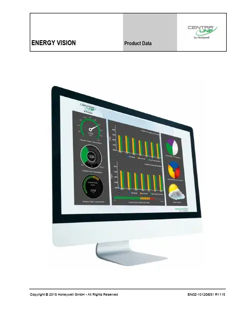
ENERGY VISION Product DataCopyright © 2015 Honeywell GmbH ▪ All Rights Reserved EN0Z-1012GE51 R1115ENERGY VISION – PRODUCT DATAEN0Z-1012GE51 R1115 2GENERALENERGY VISION is a professional tool for energy benchmarking and analysis, built on Niagara web graphics technology, andproviding a large range of techniques for managing all aspects of energy related data.EnergyVision is the ideal system to:▪ help manage energy, analyze, and optimize theoperation of facilities and▪ measure performance across multiple levels within yourbuilding or estateIt is fully web-enabled and able to integrate data from a wide range of existing systems. HAWK and ARENA AX can provide data from most of the metering devices used in the market. It enables an integrated solution, allowing the user to collate and manage all aspects of their energy data at a central location.FEATURES - BENEFITSFeatureBenefitsCompletely integrated into Niagara AXSave costs. NO additional equipment needed.Get metering data from most of the metering communication protocols in the market.Automatically collect and aggregate metering dataNo need for expensive data collection devices.Reliable and continuous data collection. No need to send thehousekeeper to note metering data. Monitor energy con-sumption with daily, weekly , monthly or annual profilesEasily recognize waste of energyAnalyse energy profiles Detect waste of energy. Optimize energy efficiency. Translate raw energy values into monetary unitsAlways have an overview of the energy costs.Compare actual costs with budget. Energy Benchmarking graphs, with weekly, monthly, yearly viewsProve the efficiency of your energy saving actions.Easily understand how your energy consumption is against targetprofiles or historical consumptions. Visualization andranking of consumptionbetween meters, zones, systems, buildings, sitesGet an overview of your highest consumers. Start optimizing your energy efficiency, where you can achieve the biggest savings. Instant and automatic reports for users,energy managers and auditorsSave costs for generating energy reports.Have the relevant data for energy managers and auditors with highest accuracy and just in timeKiosk Mode - a rotating sequence of easyunderstandable energy efficiency dataUse in a building foyer or reception area to raise occupants awareness.Honeywell offers the complete meter portfolioHoneywell offers all the needed metering devices starting from one and three phase electrical meters, heating , cooling energy meters, hot and cold water meters and all kinds of flow meters.FeatureBenefitsCost-efficient solutionLogos & layout can be customized free of chargeAll components are part of an AX palette – low effort for technical supportexisting BACnet Schedules can be usedLow training effort for engineers and usersLow training efforts for customers and partners/ engineersTraining video available on the partner webVery easy installation and start-up∙ UNIQUE SELLING POINTS 100% Web-Enabled Architecture The ENERGY MANAGEMENT is a 100% web-enabled software. This means that:- Needs to be installed at only a single location; - Can be accessed via the internet or intranet;- Requires only one browsers (Internet Explorer, Firefox, or Opera) to access it from the client PC;- Can be managed from a single central location, thus making installation and ongoing maintenance simple and cost-effective.∙ Ability to Integrate Data from a Variety of Sources ENERGY VISION is able to integrate data from a wide range of existing systems. HAWK and ARENA AX can provide data from most commercially available metering devices. ARENA supports the data exchange between the L ON W ORKS network, M-Bus, and all existing Honeywell installed base to the energy management suite. This makes it unnecessary to completely replace the system. ENERGY VISION enables an integrated solution, allowing the user to collate and manage all aspects of their energy data at a central location. ∙ Energy AnalysisThe software detects energy waste using a number of predefined analysis templates of metering data, including heating/ cooling energy, electricity, water, and other meters. ENERGY VISION proactively monitors facilities and identifies opportunities for cost savings.The software supports intelligent metering components with normalization of data, handling meter roll-over, and periods of missing data.ENERGY VISION – PRODUCT DATA3 EN0Z-1012GE51 R1115∙ Analyze Energy ProfilesBuilding management systems, utility smart meters, data loggers, and utility online databases are rich with data, yet many customers find the data difficult to acquire, aggregate, analyze, and leverage. ENERGY VISION delivers this information in real-time, providing the intelligence needed for proactive business and energy management decisions. ∙ OptimizeENERGY VISION uncovers opportunities for efficiency gains and provides data to continuously optimize the performance of each of these building systems - without affecting the comfort of occupants. Once building systems are optimized, ENERGY VISION helps keep the systems operating at highly efficient levels so that you can realize long-term energy reductions and extended equipment life. ∙ Financial AnalysisThe financial tools within the Energy Management software enable users to convert energy usage into monetary values. Users input single-tariff utility contracts to convert kWh to financial data. In addition, users are able to create and analyze consumption or financial targets. ∙ ReportsCombining historical usage information and energy analytics with real-time data feeds provides usable information and justification for both operational and capital business decisions. With ENERGY VISION, you can proactively monitor your facility and identify opportunities for cost savings. ∙ Different UsersENERGY VISION can be engineered to support different users, energy managers with access to the complete functionality, and users with limited access rights.ENGINEERINGThe ENERGY VISION engineering can be done using COACH AX or ARENA AX .KEY ENERGY ANALYSIS FEATURESDaily ConsumptionDetect inefficient energy usage by comparing multiple days across their 24-hr periods.Energy RankingVisualize and compare the performance of your sites,buildings and plants. Start energy efficiency actions optimizing your biggest consumers.Energy PerformanceCompare your actual energy consumption with your planned target consumption. Display energies in range, below, and above estimated ranges.Energy BenchmarkingDetect low energy-efficiency areas by comparing con-sumptions against similar periods, e.g., days, weeks , months, years....ENERGY VISION – PRODUCT DATAEN0Z-1012GE51 R1115 4Energy ContributionGet an overview of the energy or monetary energycontribution for different zones, buildings, or time periods.Energy Efficiency ReportsSave management effort, generating booklets of reports, e.g., for the energy manager, departments, or energy audits.ENERGY VISION – PRODUCT DATA5 EN0Z-1012GE51 R1115Energy Signature ET AnalysisDiscover anomalies in energy consumption by visualizing the effect of the outside temperature on the energy consumption.Regression AnalysisCompare your consumption with the line-of-best-fit against outdoor temperature, degree days, or any other value of interest.Kiosk ModeGet an overview of the most important energy consumers - show a rotating sequence ofenergy dashboard pages ideal for use in a building foyer or reception area.PLATFORM REQUIREMENTSCentraLine ENERGY VISION is designed to run on Niagara 3.8 on the following platforms:CLEMC12 runs on HAWK 600 with Niagara 3.8 or any other ARENA AX Supervisor.All the other products – e.g., CLEMDEMO, CLEMS75,CLEMSPRO and CLEMADVCHARTS - will run on ARENA AX Niagara 3.8 only and the following Windows platforms:▪ Microsoft® Windows Server 2012 Standard/ Enterprise SP2 (64 bit)▪Microsoft® Windows Server 2012 R2 Standard/ Enterprise SP2 (64 bit)▪ Microsoft® Windows 7 Professional/ Enterprise/ Ultimate (32/64 bit).▪ Microsoft® Windows 8 Professional/ Enterprise/ Ultimate (32/64 bit).▪ Microsoft® Windows 8.1 Professional/ Enterprise/ Ultimate (64 bit)▪ Microsoft® Windows 10 64 Bit ▪VMware – ESXi 5.1.0▪Microsoft Virtual Se rver 2008We do not currently provide support for CentraLine ENERGY VISION on any other platforms.ENERGY VISION – PRODUCT DATAEN0Z-1012GE51 R1115 6ENERGY VISION PCThis chapter defines the minimum and recommended hard-ware requirements for the installation of ENERGY VISION. The hardware specification should be used as a guide only, as the number of concurrent users, metering channels, and read frequency will affect the specific hardware required.Specification Minimum Recommended Processor type Intel® Core™ i3 Intel® Core™ i5, i7 Processor speed 3.2 GHz 4.0 GHz RAM16 GB 24 GB Hard disk space 240 GB500 GBOS requirements Windows 7 proWindows 7/10 proOS Type 32 Bit 64 BitDisplayVideo card and monitor capable of displaying 1024 x 768 pixel resolution or greaterNetwork Support Ethernet adapter (10/100 Mb with RJ-45 connector)ConnectivityFull-time high-speed ISP connection recommended for remote site access (i.e. T1, ADSL, cable modem)ENERGY VISION PRODUCTSCentraLine ENERGY VISION provides the following functionality:Product DescriptionCLEMC12License for HAWK orARENA AX with max. 12 metersCLEMDEMO Three-month demo version for customer trial job sites CLEMS75Basic supervisor license for ARENA AX with maximum 75 metersCLEMSPROProfessional supervisorlicense for ARENA AX for max.1400 meters and 5 sitesCLEUPGR75PRO Upgrade from SupervisorBasic to Supervisor professional CLEMADVCHARTS Advanced Charts andReports Tenant Billing Future module Will be available in Q4 2016SOFTWARE DOWNLOADSYou can find the following files on the DONWLOADS sectionof the PARTNER web https:// : ∙ Software files ∙ Release bulletin ∙ Training Video∙ Link to the Demo Station (which can be accessed only outside the Honeywell network)You need an account for the CentraLine PARTNER web.InstallationTo install the software, copy the java files into the COACH AX modules directory:…\CentraLine\COACHAX-3.8.38\modulesCopy the demo station in the COACH AX station directory: …\CentraLine\COACHAX-3.8.38\stationsCheck the software version using the Software Manager of the platform.LicensingFor licensing your software, you need an account for the Niagara Central.Honeywell will provide unbundled licenses for the software you have ordered.To create your bundled licenses, you must log-in to theNiagara Central and host create the software licenses, adding your host IDs and serial numbers for HAWK controllers toENERGY VISION – PRODUCT DATA7 EN0Z-1012GE51 R1115Products and Features of the Basic ProductsFeature/ LicenseCLEMC12CLEMDEMO; CLEMS75; CLEMSPR Web-based system, accessible from anywherelimited Energy benchmarking graphs, with weekly, monthly, or yearly views to compare this week, against last week, against this week last yearMonitoring & Targeting against historic, pre-set, or degree day data.High number of users with user segregation limited Automated email of energy reportsAggregation of meter data to compare energy profiles or peak demands for different zones, buildings, or sites.Ranking of consumption between meters, zones, systems, buildings, sites etc…Support for a wide variety of meter communications including Modbus & MBUS protocolsImport or export meter data using .csv files, SQL, web services, etc…limited Kiosk mode – displays a selection of pages in a rotating sequence for display in a building reception areaInstant reports – generated from each graph or chart as csv or pdf.automatically generated reports to PDF file and saved locally, or sent to email accounts.Support of multiple languages. Language is a user property Energy Temperature Analysis available December 2015Components of Advanced ChartsFeature/ License∙ Stacked bar charts (Energy Contribution) ∙ Enhanced Regression Analysis graph ∙ Base load analysis∙ Inside / Outside schedule comparison ∙ Multiple Y Axis chartENERGY VISION – PRODUCT DATAManufactured for and on behalf of the Environmental and Combustion Controls Division of Honeywell Technologies Sàrl, Rolle, Z.A. La Pièce 16, Switzerland by its Authorized Representative:CentraLineHoneywell GmbHBöblinger Strasse 1771101 Schönaich, Germany Phone +49 (0) 7031 637 845 Fax +49 (0) 7031 637 740 *******************Subject to change without notice EN0Z-1012GE51 R1115SYSTEM DIAGRAMThe picture below outlines a typical system architecture:You should connect maximum 1400 meters and five sites to a professional license CLEMSPRO. When your project size is bigger, you can install several licenses distributed in the network. You can access the data of the remote stations via remote access. The remote station licenses can be:∙ CLEMC12 ∙ CLEMS75∙ CLEMSPROFor the scalable solution, you simply create a cluster of ENERGY VISIONSupervisors which collect and aggregate the meter data, and a single ENERGY VISION Supervisor which is the user interface. It works very much in the same way as a BMS system. One Niagara instance is used to host the graphics, and multiple HAWKs collect the data.For ENERGY VISION, one instance is used for graphics, and multiple HAWKs or supervisors are used to host the meter aggregators.The software contains a driver which is built into every copy of ENERGY VISION to handle the communication between the user interface and the aggregators. This creates proxy copies of the aggregators in the user interface station, but the aggregators are processed in a remote supervisor or HAWK controllers.。

Immersion CoolerNeoCool DipModel BE201/201F/301Instruction ManualFirst Edition●Thank you for choosing BE series immersion NeoCool Dip coolers from Yamato Scientific Co., Ltd.●For proper equipment operation, please read thisinstruction manual thoroughly before use. Alwayskeep equipment documentation safe and close athand for convenient future reference.Warning: Read instruction manual warnings andcautions carefully and completely beforeproceeding.Yamato Scientific America Inc.Santa Clara,CAPrinted on recycled paper1. SAFETY PRECAUTIONS (1)Explanation of Safety Symbols (1)Symbol Glossary (2)Warnings & Cautions (3)2. PRE-OPERATION PROCEDURES (4)Placement Precautions & Procedures (4)3. COMPONENT NAMES & FUNCTIONS (10)Main Unit Overview (10)4. OPERATION PROCEDURE (12)Main Operation (12)Cooling Capacity Curves (Reference Data) (13)Choosing Coolant for Low-T emp Applications (Reference Data) (15)5. HANDLING PRECAUTIONS (16)6. INSPECTION & MAINTENANCE (17)7. STORAGE & DISPOSAL (18)Extended Storage / Unit Disposal (18)Disposal Considerations (18)8. TROUBLESHOOTING (19)Troubleshooting Guide (19)9. SERVICE & REPAIR (20)10. SPECIFICATIONS (21)11. WIRING DIAGRAM (22)12. LIST OF HAZARDOUS SUBSTANCES (23)1.Explanation of Safety SymbolsSymbol GlossaryGeneral WarningDanger!: HighVoltageDanger!:Extremely HotDanger!: MovingPartsDanger!: BlastHazardGeneral CautionCaution:Shock Hazard!Caution: BurnHazard!Caution: Do NotHeat WithoutWater!Caution: MayLeak Water!Caution: WaterOnlyCaution: T oxicChemicalsGeneralRestrictionNo Open FlameDo NotDisassembleDo Not T ouchGeneral ActionRequiredConnect GroundWireLevel InstallationRequiredDisconnect PowerInspectRegularly1.Warnings & CautionsWarning Do not install or operate CF301 unit near flammable or explosive gases/fumes. Unit is NOT fire orSubstances” (PAlways ground this unit properly to avoid electric shock.Damagingshock to the operator.NeverHazardous Substances” (PBe sure there is adequate ventilation when working with certain flammable substances (such as ethanol, etc.), which evaporate quickly at or below room temperature, and emit flammable fumes. Insufficient ventilation may cause a fire or explosion.Caution2. Placement Precautions & ProceduresWarningOutlet with ground receptacleOutlet with no ground receptacle Ground adapterGround wireW 3-pronged ground w G3-pronged plug withground 115V AC onlyPlacement Precautions & ProceduresWarning4. DO NOT disassemble or modify.Attempting to disassemble or modifiy this unit in any way may result in malfunction, electric shock.Placement Precautions & ProceduresWarningCaution 6. Place on level surfaces.Place unit on a level and even surface. Failure to do so may result in abnormal vibrations ornoise and damage to the refrigeration system.Placement Precautions & ProceduresCautionPlacement Precautions & ProceduresCautionPlacement Precautions & Procedures3. Main Unit OverviewBE201 front viewBE201 rear viewPower Switch (10A)Operation LampCooling CoilPower Cable(with plug)Cooling Coil SheathHandleHeat VentMain Unit OverviewBE201F/301 front viewBE201F/301 rear viewPower Switch (10A)Operation LampHandle Flexible Cooling Tube BE201F :500mm BE301 :1000mmMain OperationImmerse cooling coil in fluid as shown in diagram below. Turn power switch (ELB) “ON” to start operation.Wait at least five minutes to resume after halting an operation (e.g. turning power off). DONOT turn power switch “ON” and “OFF” repeatedly within a short timeframe. Damage tothe refrigeration system may result.Avoid operating unit continuously at fluid temperatures abive 35°C.Cooling Capacity Curves (Reference Data)Analysis provisions・External temperature:23°C・Power:115V AC・CPM:50Hz・Antifreeze fluid:60% Naiburain solution (covered, stirred and heat insulated)・Fluid quantity:BE201/201F: 5 ℓ BE301: 5 ℓ /10ℓ・T emp sensor placement:container centerBE201(5L)BE301(10L)BE201F(5L)BE301(5L)Cooling Capacity Curves (Reference Data) Analysis provisions・Room temperature:20°C・Power supply:115V AC・CPM:50Hz・Antifreeze fluid:60% Naiburain solution (covered, stirred and heat insulated)・Fluid quantity:BE201/201F: 5 ℓ BE301:10ℓ・Temp sensor placement:container centerChoosing Coolant for Low-T emp Applications (Reference Data)An anti-freeze coolant solution is required for applications below 10°C. Select a Naiburain® product with freezing point of 10°C or more below objective temperature. See “select coolant based on operating temperature ” on P .10.0-10-20-30-40-500102030405060708090100-10-20-30-40-50Concentration (wt%) Naiburain ® Freezing PointsT e m p e r a t u r e (°C )Warning2. DO NOT operate equipment when abnormalities are detected.Caution2. DO NOT place objects on equipment.3. DO NOT operate equipment during thunderstorms.4. DO NOT operate dry.5. Operate equipment as directed.6. Keep upright.6.Daily general maintenance and inspection is recommended to ensure optimal performance.WarningCaution◆ Contact local dealer or Yamato sales office for further assistance.7.Extended Storage / Unit DisposalCaution WarningDisposal Considerations Dispose of or recycle this unit in a responsible and environmentally friendly manner.Yamato Scientific Co., Ltd. strongly recommends disassembling unit, as far as is possible, in order to separate parts and recycle them in contribution to preserving the global environment.Troubleshooting Guide◆If problem persists, turn off power immediately, disconnect power cable and call for service.9.When a problem occurs, terminate operation immediately, turn off main power switch (ELB) and disconnect power cable.Contact a local dealer or Yamato sales office for assistance.The following information is required for all repairs. ● Model name ● Serial Number● Date (year/month/day) of purchase● Description of problem in as much detail as possibleGuaranteed maximum supply period for repair parts is 7 (seven) years from date of discontinuation for BE series NeoCool Dip immersion coolers .“Repair parts” is defined as components which, when installed, allow for continued unit operation.See production/rating label on unit. Refer to P .11 & 12 for location.⌘1 Performance based on AC115V power supply; 20°C±5°C external temperature; 65%RH±20% humidity; no load. Performance will vary depending on operation conditions..⌘2 Protrusions excluded.11. BE201/201F/30112.Never process explosive substances, flammable substances or substances that containexplosives or flammables.Excerpt from T able 1, Hazardous Substances, of Cabinet Order of the Occupational Safety and Health Law (substances related to Articles 1, 6, and 9)Limited liabilityAlways operate equipment in strict compliance to the handling and operation procedures set forth by this instruction manual.Yamato Scientific Co., Ltd. assumes no responsibility for malfunction, damage, injury or death resulting from negligent equipment use.Never attempt to disassemble, repair or perform any procedure on BE series unit which is not expressly mandated by this manual. Doing so may result in equipment malfunction, serious personal injury or death.Notice●Instruction manual descriptions and specifications are subject to change withoutnotice.●Yamato Scientific Co., Ltd. will replace flawed instruction manuals (pages missing,pages out of order, etc.) upon request.Instruction ManualImmersion Cooler NeoCool DipBE201/201F/301First Edition:June 6, 2017Yamato Scientific America Inc.925 Walsh Avenue, Santa Clara, CA 95050Phone: 800.292.6286 / 408.235.7725。
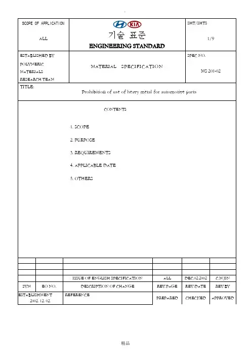
SCOPE OF APPLICATION기술표준ENGINEERING STANDARD SHT/SHTSALL1/9ESTABLISHED BYMATERIAL SPECIFICATION SPEC NO.POLYMERICMATERIALSRESEARCH TEAMMS 201-02TITLE:Prohibition of use of heavy metal for automotive partsCONTENTS1. SCOPE2. PURPOSE3. REQUIREMENTS4. APPLICABLE DATE5. OTHERSISSUE OF ENGLISH SPECIFICATION ALL DEC.02.2002 C.M.JIN SYM EO NO.DESCRIPTION OF CHANGE REV.PAGE REV.DATE REV.BYESTABLISHMENT2002. 12. 02.REFERENCEPREPARED CHECKED APPROVEDThis specification is applied to M1and N1 categories defined by EU Directive and the materials used forreplacement parts of these types of vehicles. In addition, this specification defines analysis method, method of management, and the identification of the certain heavy metals that should not be contained in. (Thisspecification does not apply to materials such as cutting oil, cleaner, masking tape and so on, which areconsumed during manufacturing process but not remained for final product).2.PURPOSE1) This specification is to prevent contamination from heavy metals used for materials and components onrunning vehicles and end-of life vehicles and to meet the international environmental regulation positively.2) The purpose of this specification is to satisfy the condition (Article 4 (2) and Annex II) that states regulationof the use of heavy metal in the process of manufacture of vehicle as laid down in EUDirective/2000/53/EC of the European Parliament and of the Council, which is effective from 10/21/2000, and to improve the environmental performance of HMC and KMC vehicles.3) This specification will be amended in order to satisfy the revised regulation of heavy metals in Directive2000/53/EC of the European Parliament and of the Council.3.REQUIREMENTS3.1The following 4 types of heavy metals shall not be used for the purpose of the automotive components and materials: Lead (Pb), Mercury (Hg), Cadmium (Cd), Hexavalent Chromium (Cr6+)3.2Exceptionally, few of heavy metal is tolerated as laid down ANNEX II of Directive 2000/53/EC. (Refer to ANNEX II)3.3The limit of impurities: Even though heavy metals are not used intentionally but they are founded as mixture of impurities, these heavy metal are tolerated within the following limitation. However the official document with signature of a representative director should be submitted as provided that these substances are not intentionally introduced.3.4 Method of Report: The document should be submitted as provided that lead, mercury, cadmium, and hexavalentchromium are not contained in each material of components. This document shall include the analysis report in accordance with lists in this reference. (If heavy metals are exceptionally tolerated as substances for materials and components, the official document should be submitted in the same way; in this case, the official document should explain explicitly that the use of heavy metals as substance for materials, components are exceptionally approved).4.APPLICABLE DATEThis specification is applied from the date of registration and it should be applied to production 6 monthsprior to the date determined by EU Directive.5.OTHERSIf there is any question with regarding to this specification, contact shall be made with Polymeric MaterialsResearch Team of Namyang Research & Development Division of HMC/KIA.< Reference I > ANAYLSIS STANDARD / REQUIREMENT OF ANALYSIS REPORT√If the analysis method is not described precisely, the analysis method with using theequivalent materials is conducted upon the agreement by professional analyticallaboratory.√Unless the method of analysis on mercury and hexavalent chromium is indicated above,the compositions of materials should be analyzed by suppliers companies and thedocument should approve that mercury and hexavalent chromium are not used.√If the analysis method is not decided, any question regarding this matter is asked toa person in charge of analysis in Polymeric Materials Research Team.√If the analysis method is performed by the suppliers companies of raw materialsthemselves, the detail explanation must be attached.√If the analysis is performed other than in Korea, the analysis should be conducted bythe certified analytical laboratory in corresponding country.2. CONTENTS OF ANALYSIS RESULTS√Date of analysis√Name of analytical laboratory and/or analyst√Correct identification of samples: The identification of material, supplier companiesof raw material, material grade and so forth should be indicated explicitly. (Ifnecessary, include identification of color used) The identification of sample shouldbe correct to be understood, and it should not be confused with that of other sample.√Standard codes of analysis method for each element√Maximum Value of tolerance√Analysis results and units√The official signature of the analytical laboratory3. ACKNOWLEDGEMENT OF ANALYSIS REPORT√The original copy of analysis report is only recognized.√However, duplicate or transcript with official signature of analytical laboratory isequally recognized as the original one.√The analysis report, which is officially issued by supplier companies of rawmaterial, is acknowledged. (However, this document should be qualified as the officialdocument by having signature of a representative director and a chief of R&D.)< Reference II > PROVISION OF EU DIRECTIVE1. DIRECTIVE1.2 Annex II (2002/524/EC) - Materials and components exempt from Article 4(2)(a)1 By 1.1.2005 the Commission shall assess whether the phase-out time scheduled for this entry has to be reviewed in relationto the availability of substitutes for lead, taking into account the objectives of Article 4(2)(a).2 See footnote n.13. By 1.1.2005, the Commission shall assess this exemption in relation to road-safety aspects.4 See footnote n.1.< Notes>- A maximum concentration value up to 0,1% by weight and per homogeneous material, for lead, hexavalent chromium and mercury and up to 0,01% by weight per homogeneous material for cadmium shall be tolerated, provided these substances are not intentionally introduced7- A maximum concentration value up to 0,4% by weight of lead in aluminium shall also be tolerated provided it is not intentionally introduced 8.- A maximum concentration value up to 0,4% by weight of lead in copper intended for friction materials in brake linings shall be tolerated until 1.7.2007 provided it is not intentionally introduced 9.- The re-use of parts of vehicles which were already on the market at the date of expiry of an exemption is allowed without limitation since it is not covered by Article 4(2)a.- Until 1.7.2007, new replacement parts intended for repair 10of parts of vehicles exempted from the provisions of Article 4(2)(a) shall also benefit from the same exemptions5 Dismantling if, in correlation with entry 14, an average threshold of 60 grams per vehicle is exceeded. For the application of this clause, electronic devices not installed by the manufacturer on the production line shall not be taken into account.6 Dismantling if, in correlation with entry 11, an average threshold of 60 grams per vehicle is exceeded. For the application of this clause, electronic devices not installed by the manufacturer on the production line shall not be taken into account.7 "Intentionally introduced" shall mean "deliberately utilised in the formulation of a material or component where its continued presence is desired in the final product to provide a specific characteristic, appearance or quality". The use of recycled materials as feedstock for the manufacture of new products, where some portion of the recycled materials may contain amounts of regulated metals, is not to be considered as intentionally introduced8 See footnote n.79See footnote n.710 This clause applies to replacement parts and not to components intended for normal servicing of vehicles. It does not apply to wheel balance weights, carbon brushes for electric motors and brake linings as these components are covered in specific entries in Annex II.如有侵权请联系告知删除,感谢你们的配合!。

Thank you for purchasing our product.MODEL RTA-TS201ASSEMBLY INSTRUCTIONSREV.052021-1•Please read carefully the assembly instructions before the installation.•Do not discard this manual or any of the packaging material until the unit has been completelyassembled.•Might require two people.ALL DONE!Give yourself a nice pat on the back. You did a great job!P.12RTA-P.12TECHNI SPORT WARRANTYGaming Chair: 2-YEAR WARRANTYGaming Desk: 5-YEAR WARRANTYGaming Chair Metal Frame: LIFETIME WARRANTYRTA Products,LLC has warranted the Techni Sport products to the original purchaser who acquired a new product from RTA Products or its authorized re-sellers of the product against defects in material or workmanship.This warranty is expressly limited to the repair or replacement(at its option)of defective product components or materials as a result of a defect in materials or workmanship.This warranty is limited to merchandise purchased in the Continental United States.No assembly labor is included.The word"defects"as used in this warranty,is defined as imperfections that impair the utility of the product.This warranty applies under conditions of normal use,but does not apply to defects that result from intentional damage,wear&tear,negligence,unreasonable use or exposure.Liability for consequential damages is excluded to the extent exclusion is permitted by law.This warranty gives you specific legal rights,and you may have other rights that vary from State to State.RTA Products does not warrant:a)natural variations in character marks b)changes in surface finishes due to aging or exposure to light c)marks,scars,or wrinkles occurring naturally in leather d)failure resulting from normal wear and tear e)the matching of colors,grains,or textures of natural materials f)the colorfastness or the matching of textiles,including an exact match to cuttings or to swatch cards g)damage,marking,or staining of veneer surfaces due to contact with rubber or similar compounds,damage from sharp objects or imprinting from writing instruments,or prolonged exposure to direct sunlight h)we do not warrant products that are exposed to extreme environmental conditions or that have been subject to improper storage.RTA Products shall not be liable for loss of time,inconvenience,commercial loss,or incidental or consequential damages.Any modification to the original product voids the warranty.We do not warrant the performance of the product when used in combination with other than original products.This product has been designed for and is intended for office,home-office and gaming use only.This warranty is Original Purchaser’s sole remedy for product defects,and this warranty does not extend to any product,or damage to any product,caused by or attributed to abuse or misuse,products used for commercial or rental purposes,use modifications of,or attachments to the product,and products or parts not used, maintained,or extended here under is in lieu of any and all other warranties,express or implied,including without limitations any implied warranty or merchant ability or of fitness for a particular purpose.Report any defects to RTA Products,LLC together with your sales receipt or other proof of purchase.If the chair is defective within the terms of the warranty,RTA Products,LLC will furnish a replacement chair(at its option)at no cost of equal or similar value and design.RTA Products will advise you of the procedure to follow in making warranty claims.The following are the procedures for warranty claims:a)Call us Monday–Friday,from9am-5pm(Eastern Time)at(866)782-5520to explain the defect and give your name,address and phone number.Please have ready the model number of our product,date and place of purchase.You can also write to us by e-mail to************************and include the same information.b)If we determine that replacement will remedy the situation,and in order to determine the extent or the cause of the defect,purchaser will need to send the part in question at purchaser’s expense.Once we receive the part,we will examine it and determine whether the claim is valid(or not),and then proceed to send the replacement.We will ship the replacement at our expense.FOR SEVERAL HELP OPTIONS INCLUDING REPLACEMENT PARTS ORDERS _________________________________________________________________VISIT:CLICK ON SUPPORT TABScan QR Code to order replacement partsOR EMAIL US:**************************P .13RTA-TS201P .13。
TS-201 Turbo Station 使用手冊 (版本:1.0.0)版權所有2006© 威聯通®科技股份有限公司序言首先,感謝您購買威聯通®公司產品。
此使用手冊將會介紹您如何使用本產品,請您依循手冊指示開始享用TS-201的強大功能。
注意•產品規格若有變動,恕不另行通知。
•所有在本站提及的商標、註冊商標,商品名稱均為其相關持有人所有。
有限保證責任威聯通®保證所有出廠的網路伺服器皆通過嚴格而完整的測試,在一般的使用情況下,都可以正常地運作。
在保固期限內及正常使用的狀況下,如果發生系統故障,威聯通®將負責修護。
除此之外,威聯通®不保證負責所有因為本產品而造成的資料遺失、毀損、或營業上及執行業務的損失。
在任何情況下,威聯通®所負擔的賠償責任,不超過本產品的售價。
注意事項1.請務必定期備份硬碟中的資料,以避免任何意外、人為操作疏失或硬碟故障所造成的資料毀損。
威聯通®不負責任何資料遺失或復原。
2.如要把TS-201 Turbo Station或任何包裝內零件退回或維修,請確定貨品妥善包裝以確保運送無誤。
若貨品運送期間因不妥善包裝造成任何損壞,威聯通®一概不予負責。
安全須知1.本產品的工作溫度介於0℃~35℃,相對濕度為0%~85%。
請確保其放置場所通風良好。
2.與本產品所連接的線路和裝置必須能提供本產品正常的電量(60W,90~264V),以確保其運作正常。
3.切勿將產品放置在直接受陽光曝曬或靠近化學藥劑的場所。
請確保其所在環境恆定溫度與溼度的維持。
4.清潔時,先將電源插頭及所有線路拔下,再以濕布擦拭即可。
切勿使用任何化學藥劑或噴霧式清潔劑。
5.為確保機器正常運作,以及避免機器過熱,切勿將任何物品或重物放置於機器上。
6.安裝硬碟時,請務必使用平頭螺絲將硬碟固定在硬碟抽取盒上,以確保其運作正常。
7.切勿使產品靠近水源。
目录1 TM2101N_JN试验机测控系统简介 (2)1.1主要功能特性 (2)1. 硬件 (2)2. 软件 (2)1.2主要规格及技术参数 (3)1.3正常工作条件 (3)2 TM2101N_JN软件安装和升级指南 (4)2.1本软件对计算机硬件系统的最低配置要求: (4)2.2 本软件对计算机软件系统的要求: (4)2.3 软件安装光盘内容介绍 (4)2.4 软件安装指南: (4)2.5 软件升级指南: (7)3 TM2101N_JN软件操作指南 (11)3.1 快速入门 (11)3.2 主界面介绍 (12)3.3 菜单介绍 (17)3.4 各功能详解 (19)1. 登陆 (19)2. 权限管理 (19)3. 修改登陆密码 (18)4. 单位系统 (19)5. 校准 (19)6. 联机 (27)7. 系统设置 (27)8. 语言切换 (27)9. 选项 (28)10. 注册 (28)11. 激活 (29)12. 测试标准编辑 (29)13. 报表编辑 (41)14. 手动取点 (42)15. 图形操作 (43)3.5 快捷键一览 (42)3.6 配置文件: (42)4 常见问题与解决方法 (44)1 TM2101N_JN试验机测控系统简介本测控系统专为拉力机、压力机、电子万能材料试验机而研制。
适用于测定各种材料在拉伸、压缩、弯曲、剪切、撕裂、剥离、穿刺等状态下的力学性能及有关物理参数。
可做拉伸、压缩、三点抗弯、四点抗弯、剪切、撕裂、剥离、成品鞋穿刺、纸箱持压、泡棉循环压缩、弹簧拉压及各种动静态循环测试。
1.1主要功能特性1. 硬件主控制器采用21世纪最先进的32位ARM处理器, 处理速度达到奔腾级通用计算机的水平,相比传统的8位单片机测控系统整体性能大大提高,运算速度更快,控制精度更高.数据采集核心器件采用美国最新型超高精度24位AD,采样速率可达2000次/秒,可捕捉到力量的瞬间变化过程,全程不分档分辨力最高达500000分度。
Ambient Light Sensor in 0805 PackageDESCRIPTIONTEMT6200FX01 ambient light sensor is a silicon NPN epitaxial planar phototransistor in a miniature transparent 0805 package for surface mounting. It is sensitive to visible light much like the human eye and has peak sensitivity at 550 nm.FEATURES•Package type: surface mount •Package form: 0805•Dimensions (L x W x H in mm): 2 x 1.25 x 0.85•AEC-Q101 qualified •High photo sensitivity•Adapted to human eye responsivity •Supression filter for near infrared radiation •Angle of half sensitivity: ϕ = ± 60°•Floor life: 168 h, MSL 3, acc. J-STD-020•Lead (Pb)-free reflow soldering•Material categorization: for definitions of compliance please see /doc?99912APPLICATIONS•Automotive sensors•Ambient light sensor for display backlight dimming in:-Mobile phones-Notebook computers -PDAs -Cameras -DashboardsNote•Test condition see table “Basic Characteristics”Note•MOQ: minimum order quantityPRODUCT SUMMARYCOMPONENT I PCE (μA)ϕ (deg)λ0.5 (nm)TEMT6200FX0123± 60450 to 610ORDERING INFORMATIONORDERING CODE PACKAGING REMARKSPACKAGE FORMTEMT6200FX01Tape and reelMOQ: 3000 pcs, 3000 pcs/reel. Label with I PCE group on each reel. Specifications of group A/B/C see table “Type Dedicated Characteristics”0805ABSOLUTE MAXIMUM RATINGS (T amb = 25 °C, unless otherwise specified)PARAMETERTEST CONDITIONSYMBOL VALUE UNIT Collector emitter voltage V CEO 6V Emitter collector voltage V ECO 1.5V Collector current I C 20mA Power dissipation P V 100mW Junction temperature T j 100°C Operating temperature range T amb -40 to +100°C Storage temperature range T stg -40 to +100°C Soldering temperatureAcc. reflow profile fig. 9T sd 260°C Thermal resistance junction/ambient Soldered on PCB with pad dimensions: 4 mm x 4 mmR thJA450K/WFig. 1 - Power Dissipation Limit vs. Ambient TemperatureNote•Each 3000 piece packing unit will contain a single group. The label on the bag will indicate which binned group is in the bag. A specific group cannot be ordered. Production shipments containing multiple bags will likely include multiple groups. Please design accordingly.BASIC CHARACTERISTICS (T amb = 25 °C, unless otherwise specified)PARAMETERTEST CONDITIONSYMBOL MIN.TYP.MAX.UNIT Collector emitter breakdown voltage I C = 0.1 mA V CEO 6V Collector dark current V CE = 5 V, E = 0 lx I CEO 350nA Collector emitter capacitance V CE = 0 V, f = 1 MHz, E = 0 lx C CEO 16pF Photo currentE V = 20 lx, CIE illuminant A, V CE = 5 V I PCE 4.6μA E V = 100 lx, CIE illuminant A, V CE = 5 VI PCE 7.52339μA Temperature coefficient of I PCE CIE illuminant A TK IPCE 1.18%/K LED, whiteTK IPCE0.9%/K Angle of half sensitivity ϕ± 60deg Wavelength of peak sensitivity λp 550nm Range of spectral bandwidth λ0.5450 to 610nm Collector emitter saturation voltageE V = 20 lx, 0.45 μA V CEsat0.1VTYPE DEDICATED CHARACTERISTICS (T amb = 25 °C, unless otherwise specified)PARAMETERTEST CONDITION BINNED GROUPSYMBOL MIN.MAX.UNIT Photo currentE V = 100 lx,CIE illuminant A,V CE tz51 = 5 VA I PCE 7.515μAB I PCE 1224μA CI PCE19.539μABASIC CHARACTERISTICS (T amb = 25 °C, unless otherwise specified)Fig. 2 - Collector Dark Current vs. Ambient Temperature Fig. 3 - Relative Photo Current vs. Ambient Temperature Fig. 4 - Photo Current vs. IlluminanceFig. 5 - Photo Current vs. Collector Emitter VoltageFig. 6 - Collector Emitter Capacitance vs. Collector Emitter Voltage Fig. 7 - Relative Spectral Sensitivity vs. WavelengthFig. 8 - Relative Radiant Sensitivity vs. Angular DisplacementREFLOW SOLDER PROFILEFig. 9 - Lead (Pb)-free Reflow Solder Profile acc. J-STD-020DRYPACKDevices are packed in moisture barrier bags (MBB) to prevent the products from moisture absorption during transportation and storage. Each bag contains a desiccant. FLOOR LIFETime between soldering and removing from MBB must not exceed the time indicated in J-STD-020:Moisture sensitivity: level 3Floor life: 168 hConditions: T amb < 30 °C, RH < 60 %DRYINGIn case of moisture absorption devices should be baked before soldering. Conditions see J-STD-020 or label. Devices taped on reel dry using recommended conditions 192 h at 40 °C (+ 5 °C), RH < 5 %.PACKAGE DIMENSIONS in millimetersBLISTER TAPE DIMENSIONS in millimetersREEL DIMENSIONS in millimetersLegal Disclaimer Notice VishayDisclaimerALL PRODU CT, PRODU CT SPECIFICATIONS AND DATA ARE SU BJECT TO CHANGE WITHOU T NOTICE TO IMPROVE RELIABILITY, FUNCTION OR DESIGN OR OTHERWISE.Vishay Intertechnology, Inc., its affiliates, agents, and employees, and all persons acting on its or their behalf (collectively,“Vishay”), disclaim any and all liability for any errors, inaccuracies or incompleteness contained in any datasheet or in any other disclosure relating to any product.Vishay makes no warranty, representation or guarantee regarding the suitability of the products for any particular purpose or the continuing production of any product. To the maximum extent permitted by applicable law, Vishay disclaims (i) any and all liability arising out of the application or use of any product, (ii) any and all liability, including without limitation special, consequential or incidental damages, and (iii) any and all implied warranties, including warranties of fitness for particular purpose, non-infringement and merchantability.Statements regarding the suitability of products for certain types of applications are based on Vishay’s knowledge of typical requirements that are often placed on Vishay products in generic applications. Such statements are not binding statements about the suitability of products for a particular application. It is the customer’s responsibility to validate that a particular product with the properties described in the product specification is suitable for use in a particular application. Parameters provided in datasheets and / or specifications may vary in different applications and performance may vary over time. All operating parameters, including typical parameters, must be validated for each customer application by the customer’s technical experts. Product specifications do not expand or otherwise modify Vishay’s terms and conditions of purchase, including but not limited to the warranty expressed therein.Except as expressly indicated in writing, Vishay products are not designed for use in medical, life-saving, or life-sustaining applications or for any other application in which the failure of the Vishay product could result in personal injury or death. Customers using or selling Vishay products not expressly indicated for use in such applications do so at their own risk. Please contact authorized Vishay personnel to obtain written terms and conditions regarding products designed for such applications.No license, express or implied, by estoppel or otherwise, to any intellectual property rights is granted by this document or by any conduct of Vishay. Product names and markings noted herein may be trademarks of their respective owners.© 2019 VISHAY INTERTECHNOLOGY, INC. ALL RIGHTS RESERVED。
This Digital Multimeter is intended for INDOOR USE ONL Y.1.Plug the BLACK test lead into "COM" jack of the multimeter;plug the REDtest lead into the "V" jack.2.Set the meter’s Function/Range Selector Switch to the appropriate ACV orDCV position as desired.3.Place the RED test lead onto the positive (+) side of the item being testedand the BLACK test lead onto the negative (-) (across the source/load) side of the item.BE CAREFUL not to touch any energized conductors with any part of your body.4.Read the results on the display.B.RESISTANCE MEASUREMENT Ω(OHMS)1.Plug the RED test lead into the "Ω" jack of the multimeter;plug the BLACKtest lead into the "COM" jack.2.Set the meter’s Function/Range Selector Switch to the OHM "Ω" rangefunction.3.Place the RED test lead onto one side of the item being tested and theBLACK test lead onto the other side of the item.(Polarity does not matter when checking resistance).4.Read the results on the display.C.DIODE TEST1.Plug the RED test lead into the jack of the multimeter;plug the BLACKtest lead into the "COM" jack.2.Set the meter’s Function/Range Selector Switch to the position.3.Place the RED test lead onto one side of the diode being tested and theBLACK test lead onto the other side.4.Read the results on the display.5.Reverse the test leads and again read the results on the parethe two readings.One reading should indicate a voltage drop value;the other reading should indicate an overrange (1) condition.D.DC CURRENT MEASUREMENT (AMPS)1.Plug the RED test lead into the "mA" or the "DC10A" jack of the multime-ter, as applicable;plug the BLACK test lead to the "COM" jack.2.Set the meter's Function/Range Selector Switch to the appropriate Ampsrange position as desired.•T o measure from 0 to 200mA, set the Selector Switch to the desired "DCmA" position.•T o measure from 200mA to 10 Amps DC, set the Selector Switch to the "DC10A" position.3.Disconnect the battery, or shut off the power to the circuit being tested.4.Disconnect one end of the wire or device, from the circuit where current willbe measured.5.Place the RED test lead on the disconnected wire and place the BLACKtest lead at the location from which the wire was disconnected (series con-nection).6.Reconnect the battery, or apply power to the circuit being tested.7.Read the results on the display.CAUTION:After the test is completed,shut the power off to the circuit before removing the test leads and before reconnecting any disconnected wires or devices.E.BATTERY TEST1.Plug the RED test lead into the "BAT." jack of the multimeter;plug theBLACK test lead into the "COM" jack.2.Determine the voltage rating of the battery to be tested.3.Set the meter’s Function/Range Selector Switch to the desired "BatteryTest" range.4.Place the RED test lead on the positive post of the battery under test;placethe BLACK lead on the negative post.5.Read the results on the display.MAINTENANCE1.No periodic maintenance is required other than the replacement of the battery,the fuse, and visual inspection of the meter.2.Keep the meter clean and dry.DO NOT use solvent to clean, use a damp(not wet) cloth and fully dry after cleaning.BATTERY AND FUSE REPLACEMENT1.T urn the Digital Multimeter “OFF”and remove the test leads.2.Remove the two screws on the back of the meter and separate the case.3.Replace the fuse or battery as necessary:•For battery replacement:Remove the battery from the battery com-partment and replace only with one 9-volt alkaline battery.•For fuse replacement:Remove the fuse from the fuse holder and replace with a 0.315A/250V - UL Listed Bussmann,GMA Type(Radio Shack GMA/270 series;#270-1046 ) fuse.NOTE:Use a 0.315A/250V,5x20mm type fuse ONL Y - Bussmann, GMA Type (Radio Shack #270-1046 or similar).Using an incorrect fuse may result in seri-ous injury and/or damage to the unit.4.Reassemble the case and secure with the two screws.LIMITED ONE YEAR WARRANTYThe Manufacturer warrants to the original purchaser that this unit is free of defects in materials and workmanship under normal use and maintenance fora period of one (1) year from the date of original purchase.If the unit fails with-in the one (1) year period, it will be repaired or replaced, at the Manufacturer’s option, at no charge, when returned prepaid to the Service Center with Proof of Purchase.The sales receipt may be used for this purpose.Installation labor is not covered under this warranty.All replacement parts, whether new or remanufactured, assume as their warranty period only the remaining time of this warranty.This warranty does not apply to damage caused by improper use, accident, abuse, improper voltage, service, fire, flood, lightning, or other acts of God, or if the product was altered or repaired by anyone other than the Manufacturer’s Service Center.The Manufacturer, under no circumstances shall be liable for any consequential damages for breach of any written war-ranty of this unit.This warranty gives you specific legal rights, and you may also have rights, which vary from state to state.This manual is copyrighted with all rights reserved.No portion of this document may be copied or reproduced by any means without the express written permission of the Manufacturer.THIS WARRANTY IS NOT TRANSFERABLE.For service, send via U.P.S.(if possible) prepaid to Manufacturer.Allow 3-4 weeks for service/repair.Copyright © 2013 IEC.All Rights Reserved.WARNINGResistance measurements must be made on "de-energized" (dead) cir-cuits ONL Y.Impressing a voltage across the multimeter's terminals while set to any resistance range may result in electric shock,instrument dam-age and/or damage to equipment under test.MAKE SURE equipment is completely de-energized before taking any resistance measurements.WARNINGTo avoid electrical shock and/or damage to the multimeter,ensure the power is removed from the circuit before any DIODE testing procedure is conducted.Test diodes on de-energized (dead) circuits only,never on live circuits.WARNINGTo prevent electrical shock when performing current measurements, follow all steps as indicated below DO NOT skip any steps or take any short cuts.The DC10A range is not fused.To avoid current hazard and/or damage to the tester,DO NOT try to take measurements on circuits that have more than 10 amps.DO NOT take more than 15 seconds to take the reading.A waiting period of AT LEAST 15 MINUTES is necessary between every 15 second testing period.WARNINGWhen replacing the battery or the fuse,remove only the rear panel.Do not remove or disassemble the circuit board or the front panel,these items are not serviceable and if disassembled there is the possibility of loose metal parts shorting the circuit board and causing an electrocu-tion danger to the user.。
TM201轴振动变送保护表 故障监测
★监测旋转机械转子的径向振动,
可测量轴振动,摆度,偏心等。
测量参量
★径向振动(位移)的峰峰值。
机组类型
★各种滑动轴承的旋转机械。
如汽
轮机、风机、压缩机、电机、泵等。
★适合于老机组改造。
安装要求
★对于已有涡流探头系统的机组,
只需将连线接上,设置报警点即可。
★新项目,要求与主机厂、设计院
协作,或与派利斯公司联系。
输出接口
★具有4-20mA有源输出端子
(“4-20mA”的“+”和“-”)。
★现场发光管显示机器运行状态
(仪表工作状态OK、报警Alert、
联锁Danger)。
★隔离的两级报警的继电器输出
端子SPDT(“ALERT”与
“DANGER”的6个输出端子)。
★现场报警复位键、遥控报警复位
端子(“RESET”)/报警旁路端子
(“RESET”与“COM”)。
★可现场显示(需要TM0200)以
及通过PLC、DCS显示轴位置值。
★适用各种防爆场合(需要防爆隔
离栅TM0412)。
★原始信号的缓冲输出,直接对接
状态监测仪表(“BUF OUT”同轴
电缆接口)。
★24VDC、220VAC或110VAC供
电,其中220VAC或110VAC选项
为隔离电源。
技术指标
电气指标:
外接电源:
22-30VDC,100mA,上位机供电或使用TM900。
90~220VAC供电,40~60Hz,50mA。
频响:(±3dB):
标准选项:2.0-5.0KHz;
低频选项:0.5-100Hz。
外接涡流传感器(Sensor):
接口端子:
“A/P”:-24V电源(-VT或POWER);
“B/S”:信号(SIG或OUT);
“COM”:公共端(COM或GND)。
灵敏度:同所接涡流传感器。
缓冲输出(Buf Out):
原始信号的输出。
输出灵敏度:同所接涡流传感器;
电压输出范围:2-18V(非校验);
输出阻抗:小于500Ω。
最大传输距离:300米。
线性范围(以8mm探头为例):
量程:2.00mm;
范围:0.25mm-2.25mm处。
总振动输出(4-20mA):
4-20mA,有源,可以驱动高达750
Ω的负载;
1-5V,有源,输出阻抗250Ω。
误差:
线性误差:< 1% FS(最小二乘法,
25o C);
温度系数:< 0.1% FS / o C;
报警点设置(Normal/Set):
范围:0-100%满量程;
精确度:±0.1%。
报警增益:>60dB
继电器(Alert/Danger):
密封:环氧树脂;
节点容量:2A/220VAC或2A/24VDC;
电阻性负载;
节点类型:单刀双掷,SPDT;
输出隔离:1000VDC。
报警延迟:3秒
运行状态光电管LED指示:
绿灯:系统自检通过,仪表工作正
常;
黄灯:报警指示;
红灯:联锁指示。
报警复位/报警旁路(RESET):
监测表内置报警复位键;
遥控报警复位/报警旁路端子
(“RESET”)。
物理指标
尺寸:高:75mm,其它尺寸见TM表尺
寸图。
重量:500克。
环境指标:
工作温度:-250C到+650C;
贮存温度:-400C到+1000C;
湿度:90%非凝固。
订货指南:
标准配置:
轴振动变送保护表:
TM201-A00-B00-C00-D00-E00-G00
8mm涡流探头:
TM0180-07-00-05-10-02
延长电缆:
TM0181-040-00
前置器:
TM0182-A50-B00-C00
TM201订货选项:
TM201-AXX-BXX-CXX-DXX-EX
X-GXX
AXX:满量程
A00*:0 -200 µm pk-pk
A01:0 -1000 µm pk-pk
A02:0 -100 µm pk-pk
A03:0 -10 mil pk-pk
A04:0 -50 mil pk-pk
A05:0 -5 mil pk-pk
A06:0 -200 µm pk-pk (0.5-100Hz)
A07:0 -1000 µm pk-pk (0.5-100Hz)
A08:0 -100 µm pk-pk (0.5-100Hz)
BXX:外部电源
B00*: +24VDC
B01: 220VAC
B02: 110VAC
B03: 90~250VAC
CXX:报警输出
C00*:环氧树脂密封继电器
C01:无报警
TM900:电源。
TM0412:防爆隔离栅。
TM201现场接线图
TM201系列变送保护表的安装尺寸
外形尺寸:高:75mm ,其它尺寸见图
使用TM0412防爆隔离栅,必须外接+24VDC电源。
TM表要求选用24VDC选项的。
TM表底板螺丝安装尺寸图。