好利来保险丝1A 250V规格书
- 格式:pdf
- 大小:340.43 KB
- 文档页数:7

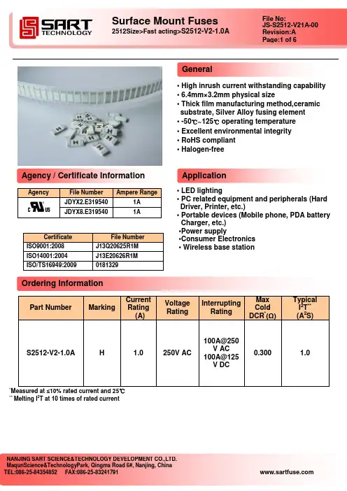
• High inrush current withstanding capability • 6.4mm×3.2mm physical size• Thick film manufacturing method,ceramic substrate, Silver Alloy fusing element• -50℃~125℃ operating temperature• Excellent environmental integrity• RoHS compliant• Halogen-free• LED lighting• PC related equipment and peripherals (HardDriver, Printer, etc.)• Portable devices (Mobile phone, PDA batteryCharger, etc.)•Power supply•Consumer Electronics• Wireless base station*Measured at ≤10% rated current and 25℃** Melting I2T at 10 times of rated currentAgency File Number Ampere RangeJDYX2.E319540 1AJDYX8.E319540 1ACertificate File NumberISO9001:2008 J13Q20625R1MISO14001:2004 J13E20626R1MISO/TS16949:2009 0181329Part Number MarkingCurrentRating(A)VoltageRatingInterruptingRatingMaxColdDCR*(Ω)TypicalI2T**(A2S) S2512-V2-1.0A H 1.0 250V AC100A@250V AC100A@125V DC0.300 1.0GeneralApplicationAgency / Certificate InformationOrdering InformationCataloS 2512- V2-1.0AShape & Dimensions: (mm)L(mm) W(mm) T(mm) B(mm) A(mm)6.40±0.20 3.25±0.20 0.55±0.20 0.85±0.20 0.30±0.20Components MaterialSubstrateCeramicTerminations Silver over-plated with nickel and tin (100%) ElementSilver AlloyDimensions A(mm) B(mm) C(mm) D(mm)Spec4.50±0.50 8.50±0.50 3.50±0.50 2.00±0.50Catalog SymbolDimensionsRecommended Land PatternsMaterialsBADC“1.0A” Ampere Rating: 1A“V2” V = fast acting, 2=250V ac“2512” Size Number: 2512=6.4mm×3.2mm physical size “S” Symbol of SARTTime Current Curve:• The current carrying capacity will be affected by ambient temperature which was showed in the figure.•This current derating curve is for fusing characteristics.Example,Work Temp:80℃,Temp derating factor = 91% I actual = I normal / 0.91Time Current CurveTemperature Derating CurveAmpere Rating % of CurrentRatingOpening Time 1A 100% >4 hours 1A 350%≤10secI 2T vs Time CurveElectrical Characteristics Temperature in degrees ℃T e m p d e r a t i n g f a c t o r %0.00010.0010.010.11101000.11101001000T i m e (s e c o n d s )Current (Amperes)Time Current Curves0.010.111010010000.00010.011100I 2T (A 2S )Time (Seconds)I 2T vs.Time CurveReliability Test:***Fuse mounted on board with 1-oz Cu traceItemTest condition/ Methods Performance Standard Voltage Drop100% In; Temperature in fuse wasstabilizedIndividual values deviate from mean value:<15% IEC 60127-1Time/Current100% InNo Fusing;4hours Min.Refer to SARTSpec 350% In*** Within 10sec1000% In***>10msEndurance Test 100% In, 1h on,15min off, 100 cycles;followed by 1h at 125%In│△R │<10% Legible appearanceIEC 60127-1 Temperature Rise 100%In │△T │<75℃UL248-14 Interrupting Ability100A@250V AC 100A@125V DCWithout permanent arcing, ignition and bursting offuse linkUL248-14 Solderability 240℃±5℃,3sec±0.5sec95% coverage Min. IEC60127-4 IEC60068-2-20 MIL-STD-202 Resistance to Soldering 260℃±5℃,10sec±0.5sec│△R│<10% Legible appearanceMIL-STD-202 IEC60127-4 Bending Test Distance between holding points :90mm; Bending :1mm ; time:10sec│△R │<10%No mechanical damages IEC 60127-4 High Temperature Operating Life 70℃±2℃, 96hours, at 60% In│△R │<10%; no fusingMIL-STD-202 M1243.ethod108 Low Temperature Storage-55℃±2℃, 96hours │△R │<10%IEC60068-2-1High Temperature Storage 125℃±2℃, 96hours │△R │<10% IEC60068-2-2 Humidity(steady state) 40℃±2℃, 90%~95%RH, 1000 hours │△R │<10% MIL-STD-202Method 103 Salt Spray 5% salt solution ,48hoursexposure │△R│<10% Legible appearance MIL-STD-202 Method 101 Thermal Shock5 cycles between -55℃/+125℃, 60 minutes ;each extreme│△R│<10%No mechanical damagesIEC 60068-2-14Reliability Test1. Infrared Reflow: Temperature :260℃ Time :5secMax.Recommend Reflow profile2.Wave soldering3.Hand Soldering Reservoir Temperature :260℃ Temperature :350℃ Time in Reservoir :10secMax. Time :5secMax.1.Embossed Tape DimensionsProfile Feature Pb-Free Assembly AverageRamp-Up Rate(Ts max to Tp) 3℃/s Max. PreheatTemperature Min(Ts min ) Temperature Max(Ts max ) Time(Ts min toTs max )150℃ 200℃60sec~120sec Peak Temperature(Tp) 260℃ Time within 5℃ of actual Peak Temperature(Tp) 5sec Melting tin time(T L ) 20sec~30sec Ramp-Down Rate6℃/s Max. Time 25℃ to Peak Temperature8 minutes Max.TypeA(mm)B(mm)E(mm)F(mm)W(mm)P0(mm)P1(mm)P2(mm)D0(mm)T(mm)2512 3.40±0.10 6.73±0.10 1.75±0.10 5.50±0.10 12.00±0.10 4.00±0.10 4.00±0.10 2.00±0.05 1.50+0.10/-0 0.81±0.10Recommended Solder CurvePackagingTop TapeResistorEmbossed Tape2.Reel DimensionsTypeA(mm) N(mm) C(mm) D(mm) B(mm) G(mm) T(mm)2512178.00±2.00 57.00±0.20 13.00±0.50 21.00±0.50 2.00±0.50 13.00±0.50 15.50±1.50● The ambient temperature shall between 5℃~30℃.● The relative humidity recommended for storage is between 25%~60%.● Sealed plastic bags with desiccant shall be used to reduce the oxidation of thetermination and shall only be opened prior to use. The products shall not be stored in areas where harmful gases containing sulfur or chlorine are present.Packaging styleTape and ReelType 2512 Quantity(PCS )4000StorageNumber of Package。
DATA SHEETPOSITIVE TEMPERATURE COEFFICIENTAC/DC POWER SUPPLYBK250 seriesRoHS compliant & Halogen freet s p e c i f i c a t i o n – O c t o b e r 06, 2020 V .1Positive Temperature Coefficient (PTC) Data SheetDescriptionThe 250V series provides radial resettable overcurrent protection with holding current from 0.03A to 2.0A. Thisseries is suitable for applications with higher working voltage up to 250V.Features■ Radial leaded devices. ■ Over-current protection■ High voltage surge capabilities■ Flame retardant epoxy polymer insulating material meets UL94 V-0 requirement. ■ Available in lead-free version.■ Meets MSL level 1, per J-STD-020 ■ Operating Temperature: -40℃~+85℃Applications■ IT equipment■ Access network equipment ■ Central office equipment■ ISDN and xDSL equipments ■ Phone set and fax machine ■ LAN/WAN and VOIP cardsPart Number Code and MakingBK 250Lead Shape Z =Straight I =Inner O=OuterY=Front and Rear Curved Holding Current Rating Voltage Rating Brand BK--Body Shape S =Square D =CircularVoltage RatingHolding Current Rating Dimensions (Unit: mm)SZEDYDZ SY SIElectrical Characteristics·I H = Hold current: maximum current device will pass without tripping in 25℃still air.·I T = Trip current: minimum current at which the device will trip in 25℃still air.·V MAX = Maximum voltage device can withstand without damage at rated current.·I MAX = Maximum fault current device can withstand without damage at rated voltage. ·R MAX = Maximum resistance of device in initial (un-soldered) state.·R MIN = Minimum resistance of device in initial (un-soldered) state.·Pd typ. = Typical power dissipation from device when in the tripped state at 25℃still air.Polymeric PTC Selecting Guide■Determine the following operating parameters for the circuits:·Normal operating current (I hold) ·Maximum interrupt current (I max)·Maximum circuit voltage (V max) ·Normal operating temperature surrounding device (min℃/max℃)■Select the device from factor and dimension suitable for the application■Compare the maximum rating for V max and I max of the PPTC device with the circuit in application and make sure the circuit’s requirement does not exceed the device rating.■Check that PPTC device’s trip time (time-to-trip) will protect the circuit.■Verify that the circuit operating temperature is within the PPTC devi ce’s normal operating temperature range.■Verify that performance and suitability of the chosen PPTC device in the application.■Mechanical Stress·PPTC devices will undergo a thermal expansion during fault condition. If PPTC devices are installed or placed in an application where the space between PPTC devices and the surrounding materials (e.g., covering materials, packaging materials, encapsulate materials and the like) is insufficient, it will cause an inhibiting effect upon the thermal expansion. Pressing, twisting, bending and other kinds of mechanical stress will also adversely affect the performance of the PPTC devices, and shall not be used or applied. ■Chemical Pollutants·Silicone-based oils, oils, solvents, gels, electrolytes, fuels, acids, and the like will adversely affect the properties of PPTC devices, and shall not be used or applied.■Electronic and Thermal Effect·PPTC devices are secondary protection devices and are used solely for sporadic, accidental over-current or over-temperature error condition, and shall NOT be used if or when constant or repeated fault conditions (such fault conditions may be caused by, among others, incorrect pin-connection of a connector) or over-extensive trip events may occur.·PPTC devices are different from fuses and, when a fault condition occurs, will go into high-resistance state and do not open circuit, in which case the voltage at such PPTC devices may reach a hazardous level.·Operation over the maximum rating or other forms of improper use may cause failure, arcing, flame and/or other damage to the PPTC devices.·Conductive material contamination, such as metal particle, may induce shortage, flame or arcing.·Due to the inductance, the operation circuits may generate a circuit voltage (Ldi/dt) above the rated voltage of PPTC devices, which shall not be used under such circumstances.■General·Customers shall evaluate and test the properties of PPTC devices independently to verify and ensure that their ind ividual applications will be met.·The performance of PPTC devices will be adversely affected if they are improperly used under electronic, thermal and/or mechanical procedures and/or conditions non-conformant to those recommended by manufacturer.·Customers shall be responsible for determining whether it is necessary to have back-up, failsafe and/or fool-proof protection To avoid or minimize damage that may result from extra-ordinary, irregular function or failure of PPTC devices.·Any and all responsibilities and liabilities are disclaimed if any item under this notice of warning is not complied with.Thermal Derating Curve-40.000.0040.0080.000.0050.00100.00150.00200.00Device Ambient Temperature (℃)P e r c e n t a g e o f R a t e d C u r r e n tThermal Derating Chart – I H (A)Test Procedures and RequirementTypical Time-to-Trip Charts @25℃00.010.11101000Fault Current (A)T i m e t o T r i p (s )AB C D E F A=BK250-030B=BK250-040C=BK250-060D=BK250-080E=BK250-090F=BK250-110G=BK250-120H=BK250-145I=BK250-180J=BK250-200K=BK250-250L=BK250-400N=BK250-600M=BK250-6001000.20.40.60.81.01.21.41.61.82.02.22.42.62.83.0G H I J L MK N0.1101000.11101001000Fault Current (A)T i m e t o T r i p (s )A B CA-BK250-1000B-BK250-1500C-BK250-20001Storage Recommendations■ Storage Temperature: -10℃~+40℃ ■ Relative Humidity: ≤80%RH■ Keep away from corrosive atmosphere and sunlight. ■ Period of Storage: 1 year.Wave Soldering Recommendation Parameters5050150Time (s)T e m p e r a t u r e (℃)100150200100200300250。
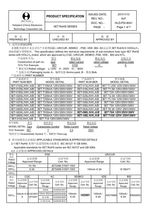
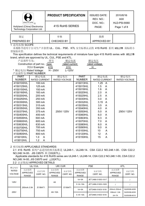
Hollyland (China) Electronics本规格书适用于本公司生产并获得CQC 、UR/CUR 、SEMKO 、PSE 、VDE 、BSI 、KC 认证的5ET RoHS 系列HOLLY 商标的超小型保险丝。
This specification defines the technical requirements of sub-miniature fuse type 5ET RoHS series with HOLLY ® 产品部件号为: brand, which are approved by CQC, UR/CUR, SEMKO, PSE, VDE 、BSI and KTL.型号 额定电流 额定电压 Construction of part no: type rated current rated voltage 5ET 0100 H A型号规格: 型号 特性符号 额定电流 MODEL DETAIL: 额定电压 Type Characteristic Symbol Rated Current 例如/ Example: Rated Voltage 5ET T 2 A *特性符号/ Characteristic Symbol: T – 慢断型/ Time-Lag.250V2. 相关标准及认证情况/ APPLICABLE STANDARDS & APPROVED DETAILS 2.1 5ET RoHS 系列产品适用的相关标准是 IEC 60127和GB 9364。
Applicable standards for 5ET RoHS series are IEC 60127 and GB 9364.Hollyland (China) Electronics3. 公司地址/ ADDRESS中国福建省厦门市湖里区枋湖路9-19号NO. 9-19, FANGHU ROAD, HULI, XIAMEN, FUJIAN, CHINA.4. 构造图/ CONSTRUCTION FIG . & DIMENSION4.2 方形塑料帽/ Square THERMOPLASTIC CAP 方形塑料帽无破裂、缺损或污染等现象。
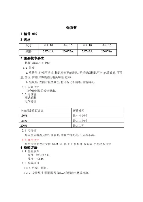
保险管1 编号0072 规格尺寸Ф4×10Ф4×10Ф4×10Ф4×10规格250V/1A 250V/2A 250V/3A 250V/4A3 主要技术要求执行 GB9364.1-19973.1 外观a重缺陷:外观不清洁,标记模糊不能辨认,无标记或标记不全;包装破碎,不防震,防压,防潮,有腐蚀性;端头锈蚀,松动。
b 轻缺陷:表面有轻微划伤,打印标记不清晰,但能辨认。
3.2 安装尺寸符合印制板的设计要求。
3.3 电性能测试通断电气特性电流额定值百分比断路时间110% 最小4小时135% 最大1小时200% 最大1秒3.4 可焊性焊锡层应覆盖元件引线表面,并且平滑光亮,不应有小滴。
3.5 外形尺寸外形尺寸见设计文件 BSZM-ZX-JS-016-外购件-保险管-外形结构尺寸4 检验方法4.1 检验条件温度:25℃±5℃;湿度:≤65%4.2 检验项目4.2.1 外观:目测。
4.2.2 安装尺寸:用钢板尺(15cm)和标准电路板检验。
4.2.3 电性能:用万用表检测通断,电气特性免检由厂家保证.4.2.4 可焊性:把元件引线放入浸焊炉,观察表面。
4.2.5 外形尺寸:使用游标卡尺测量。
5 检验规则按GB2828-2003 《逐批检查计数抽样程序及抽样表》中规定的一般检查水平Ⅱ正常检查一次抽样方案进行.安装尺寸按 GB2828-2003 特殊检查水平 S-4可焊性每批抽取 10 只,Ac=0 Re=16 质量判定项目外观重缺陷外观轻缺陷电性能外形尺寸AQL 1.0 4 0.4 4.0。
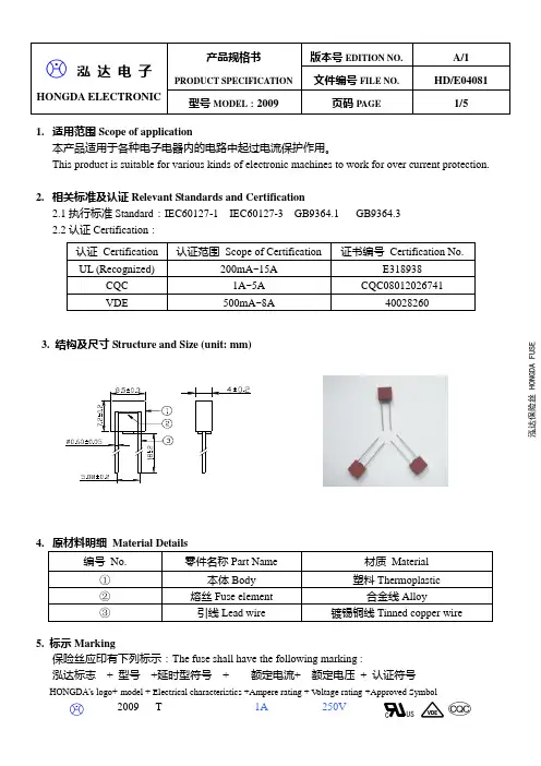
HONGDA ELECTRONIC1. 适用范围Scope of application本产品适用于各种电子电器内的电路中起过电流保护作用。
This product is suitable for various kinds of electronic machines to work for over current protection.2. 相关标准及认证Relevant Standards and Certification2.1执行标准Standard :IEC60127-1 IEC60127-3 GB9364.1 GB9364.3 2.2认证Certification :3. 结构及尺寸Structure and Size (unit: mm)4.5. 标示Marking保险丝应印有下列标示:The fuse shall have the following marking :泓达标志 + 型号 +延时型符号 + 额定电流+ 额定电压 + 认证符号 HONGDA’s logo+ model + Electrical characteristics +Ampere rating + V oltage rating +Approved Symbol2009 T 1A 250V泓达保险丝 H O N G D A F U SECUSHONGDA ELECTRONIC6. 外观Appearance6.1外观不应有显著的污点、裂纹。
There shall not be any remarkable stain ,rust or crack on the appearances. 6.2标示应该很容易辨识。
Marking shall be easily legible.7. 机械特性Mechanical characteristics 7.1 拉力强度试验Tensile test将保险丝固定好后,对保险丝两端引线施加5N 的轴向拉力,持续1分钟。
南京科邦電子有限公司NANJING CO-TECH ELE. CO., L TD.ISO9001:2008RF ®250V SERIES产品标识Product Identification产品系列Products Series 注:后缀A表示引线式;B代表插件式;C代表特种产品;D代表带式;M S代表M in i S MD贴片式工作电流值Current value额定电压值Rated voltage产品电气参数Product Electrical CharacteristicsModelI hold( A )I trip( A )V max( V )I max( A)Time-to-trip P(d) R. min R. maxI trip(A)T. max ( W ) (Ω)(Ω) RF250-060B 0.06 0.12 250 3 1.00 0.50 1.0 22.00 32.0RF250-080B 0.08 0.16 250 3 0.35 3.00 1.0 14.00 22.0RF250-090B 0.09 0.18 250 3 0.35 3.00 1.0 10.00 20.0RF250-110B 0.11 0.22 250 3 1.00 0.75 1.0 7.00 11.0RF250-120B 0.12 0.24 250 3 1.00 0.75 1.0 8.00 12.0RF250-145B 0.145 0.29 250 3 1.00 2.50 1.0 3.50 6.5RF250-180B 0.18 0.36 250 10 1.00 15.00 1.0 0.80 2.0RF250-200B 0.20 0.40 250 10 1.00 15.0 1.5 1.50 3.0RF250-400B 0.40 0.80 250 10 2.00 10.0 2.5 0.75 0.95RF250-600B 0.60 1.20 250 10 3.0 10.0 3.00 0.50 0.70RF250-700B 0.70 1.40 250 10 3.0 10.0 3.5 0.6 0.70RF250-800B 0.80 1.60 250 10 4.0 8.0 3.5 0.45 0.65RF250-1000B 1.0 2.0 250 10 5.0 10.0 4.0 0.28 0.45RF250-1200B 1.20 2.40 250 10 6.0 10.0 5.0 0.25 0.30RF250-1400B 1.40 2.80 250 10 7.0 12.0 5.0 0.18 0.25RF400-040B 0.04 0.08 400 3 0.20 3.12 / 70 110RF400-050B 0.05 0.10 400 3 0.25 3.08 / 55 90RF600-075B 0.075 0.15 600 3 0.375 10.0 / 15 30RF600-110B 0.11 0.22 600 3 0.55 10.0 / 10 24RF600-150B 0.15 0.30 600 3 1.0 5.0 / 612RF600-200B 0.20 0.40 600 3 1.0 5.0 / 5 9 注解Comment:IH:Hold current-maximum current at which the device will not trip at 25℃Pdmax: Power dissipated from device when in the tripped state in 25℃ still air It: Trip current-minimum current at which the device will always trip at 25℃R max: Maximum device resistance at 25℃ prior to tripping Vmax: Maximum voltage device can withstand without damage at rated R min: Minimum device resistance at 25℃ prior to tripping Imax: Maximum fault current device can withstand without damage at rated Time-to-trip: Over loading current & time工作电流值与环境温度折减表Product Rate Temperature & I t r i pModel -40℃-20℃0℃25℃40℃50℃60℃70℃85℃RF250-060B 0.110 0.095 0.080 0.060 0.056 0.051 0.047 0.040 0.032 RF250-080B 0.124 0.110 0.095 0.080 0.066 0.059 0.051 0.044 0.036 RF250-090B 0.130 0.124 0.100 0.090 0.085 0.079 0.063 0.058 0.040 RF250-110B 0.171 0.151 0.131 0.110 0.091 0.081 0.071 0.061 0.046 RF250-120B 0.191 0.170 0.148 0.120 0.104 0.093 0.082 0.071 0.055 RF250-145B 0.225 0.199 0.172 0.145 0.119 0.106 0.093 0.080 0.060 RF250-180B 0.269 0.240 0.211 0.180 0.153 0.138 0.123 0.109 0.087 RF250-200B 0.310 0.270 0.240 0.200 0.173 0.153 0.134 0.120 0.095 RF250-400B 0.56 0.51 0.47 0.40 0.35 0.30 0.24 0.192 0.172 RF250-600B 0.98 0.81 0.66 0.60 0.57 0.49 0.43 0.33 0.23 RF250-800B 1.10 0.96 0.89 0.80 0.73 0.67 0.54 0.44 0.31 RF250-1000B 1.49 1.34 1.20 1.00 0.91 0.86 0.79 0.67 0.58 RF250-1200B 1.51 1.37 1.25 1.20 1.10 0.81 0.74 0.62 0.55 RF250-1400B 1.47 1.56 1.49 1.40 1.35 1.19 1.00 0.88 0.67 RF600-150B 0.238 0.211 0.183 0.150 0.128 0.115 0.101 0.088 0.067 RF600-160B 0.250 0.220 0.195 0.160 0.137 0.123 0.110 0.095 0.074。
af250导线标准
AF250导线标准是一种特殊的导线,其标准为Q/IRMV1-2008。
这种导线由实芯或绞合镀银或镀镍铜线制成,具有以下特性:
1. 额定电压:600V。
2. 工作温度范围:-80℃至+250℃,短时间可耐受300℃的高温。
3. PFA铁氟龙用途:这种导线材料具有优良的耐腐蚀性能,抗油、强酸、抗强碱、强氧化剂等。
同时,它还具有良好的电绝缘性能、耐高电压、高频损耗小、不吸潮、绝缘电阻大等特性。
此外,PFA铁氟龙还具有优良的耐燃、耐老化性能,使用寿命长。
4. 防震、防水、防紫外线和抗化学腐蚀等特性,能够保证设备的稳定性和安全性。
5. 使用范围:AF250导线标准适用于连接30A到120A的电气设备,常见应用包括制冷设备、加热设备、风扇、照明设备和电动工具等。
同时,由于其质量可靠、结构紧凑,也被广泛应用于船舶、轨道交通、军工等领域。
以上信息仅供参考,如需了解更多信息,建议查阅AF250导线标准的相关资料或者咨询专业人士。
250sr保险盒说明摘要:1.250sr 保险盒概述2.250sr 保险盒的功能特点3.250sr 保险盒的使用方法4.250sr 保险盒的注意事项5.250sr 保险盒的优点与不足正文:一、250sr 保险盒概述250sr 保险盒是一款具有多功能、高性能的保险盒,适用于各种工程和实验场合。
其主要功能是为电路提供过载保护、短路保护以及过温保护等,有效防止电路故障,确保设备正常运行。
二、250sr 保险盒的功能特点1.多重保护:250sr 保险盒具备过载保护、短路保护和过温保护功能,可以全面保护电路免受损坏。
2.响应速度快:250sr 保险盒具有快速响应的特性,当电路出现异常时,能迅速切断电源,防止设备受到过大的损害。
3.稳定性高:250sr 保险盒采用高品质材料制造,具有良好的抗干扰性能和稳定性,可以长时间稳定工作。
4.适用范围广:250sr 保险盒适用于各种电压、电流的电路,可以满足不同场合的使用需求。
三、250sr 保险盒的使用方法1.在使用前,请先检查保险盒是否符合电路的电压、电流等参数要求。
2.将保险盒正确接入电路,确保接线牢固。
3.在使用过程中,应注意观察保险盒的工作状态,如有异常应及时处理。
4.在更换保险丝时,应选择与保险盒参数相匹配的保险丝,不可随意使用不同规格的保险丝。
四、250sr 保险盒的注意事项1.在使用过程中,应避免保险盒受到剧烈震动或撞击,防止损坏。
2.不要在潮湿、高温的环境中长时间使用保险盒,以防影响其性能。
3.在使用过程中,如发现保险盒有异常现象,应立即切断电源,并联系专业人员进行检修。
五、250sr 保险盒的优点与不足1.优点:250sr 保险盒具有多功能、高性能、稳定性高等优点,可以全面保护电路免受损坏,适用于各种工程和实验场合。
Hollyland (China) Electronics本规格书适用于本公司生产并获得CQC 、UR/CUR 、SEMKO 、PSE 、VDE 、BSI 、KC 认证的5ET RoHS 系列HOLLY 商标的超小型保险丝。
This specification defines the technical requirements of sub-miniature fuse type 5ET RoHS series with HOLLY ® 产品部件号为: brand, which are approved by CQC, UR/CUR, SEMKO, PSE, VDE 、BSI and KTL.型号 额定电流 额定电压 Construction of part no: type rated current rated voltage 5ET 0100 H A型号规格: 型号 特性符号 额定电流 MODEL DETAIL: 额定电压 Type Characteristic Symbol Rated Current 例如/ Example: Rated Voltage 5ET T 2 A *特性符号/ Characteristic Symbol: T – 慢断型/ Time-Lag.250V2. 相关标准及认证情况/ APPLICABLE STANDARDS & APPROVED DETAILS 2.1 5ET RoHS 系列产品适用的相关标准是 IEC 60127和GB 9364。
Applicable standards for 5ET RoHS series are IEC 60127 and GB 9364.Hollyland (China) Electronics3. 公司地址/ ADDRESS中国福建省厦门市湖里区枋湖路9-19号NO. 9-19, FANGHU ROAD, HULI, XIAMEN, FUJIAN, CHINA.4. 构造图/ CONSTRUCTION FIG . & DIMENSION4.2 方形塑料帽/ Square THERMOPLASTIC CAP 方形塑料帽无破裂、缺损或污染等现象。
Square Thermoplastic Cap shall have no defects such as crack, injury and contamination. 4.3 塑料件阻燃性能/ FLAMMABILITY CIASSIFICATION: UL 94V-0. 5. 机械特性/ MECHANICAL PERFORMANCES保险丝应能承受下列二项试验。
Fuse shall withstand the following two tests. 5.1 拉力试验/ TENSILE TEST将保险丝保持在一个固定的位置,沿引线方向施加10N 的拉力,引线、方形塑料帽不能松动并且方形塑料帽不应破裂。
When fuse is fixed and the tensile force 10N is applied in a direction to lead, no looseness of leads and square thermoplastic cap or damage of square thermoplastic cap shall occur. 5.2 推力试验/ THRUST TEST将保险丝保持在一个固定的位置,沿引线方向旋加2N 的推力,引线、方形塑料不能松动并且方形塑料不应破裂。
When fuse is fixed and the thrust 2N is applied in a direction to lead, no looseness of leads and square thermoplastic cap or damage of square thermoplastic cap shall occur.6. 电气特性/ ELECTRICAL PERFORMANCES 6.1 测试条件/ TEST CONDITIONSA 全部测试条件都应在环境温度24℃±3℃条件下进行,在此期间温度变化不允许达到+5℃和到极限范围。
All electrical tests are conducted at a ambient temperature of 24±3℃. The ambient temperature is not allowedRemark: ① S quare Thermoplastic Cap ②S quare Base Long Lead Short Lead 7.2备注:①方型塑料帽 ②方型底座长引线 短引线Hollyland (China) Electronicsto vary more than 5℃ during the test, and must be within these limits.B 每个保险丝支架,水平安装在不导电的胶木测试板上,以便被测的保险丝在测试板上能保持水平。
Each fuse-holder is to be mounted horizontally on a test board of non-conducting bakelite, so that each fuse under test is held in a horizontal position above the board .6.2 电压降、平均I 2T 值(供参考)、最大持续功耗/ VOLTAGE DROP , AVERAGE I 2T VALUE (FOR REFERENCE ONLY)6.3 负载能力测试/ CURRENT-CARRYING CAPACITY TEST当保险丝通以150%倍额定电流的条件下进行测试时,在1小时内电路不应断开,保险丝不被电流熔断,方形塑料帽不破裂、脱落。
A fuse shall carry 150% of rated current for 1 hour or more, and the circuit shall not be opened. While the fuse is carrying this current, no open circuit, melt fusible element, and square thermoplastic cap shall not be charred or ruptured in any manner.6.4 预飞弧时间-电流特性/ PRE-ARCING TIME-CURRENT CHARACTERISTICS当保险丝通以下表规定的电流时,其熔断时间必须符合下表的要求,且方形塑料帽不能飞脱、损坏。
When the current in the following table is passing the fuse, its opening time must be in accordance with the requirements in the following table, that is, the pre-arcing time. Moreover, there shall be not damaged or shattered of the square thermoplastic cap.6.5 分断能力/ BREAKING CAPACITY保险丝的分断能力应能达到下表规定的相应的各种安全认证的分断能力要求。
保险丝分断电路后,方形塑料帽不应飞脱、损坏。
The breaking capacity should reach the rated breaking current given in the following table. And after this test, there shall be not damaged or shattered of the square thermoplastic cap.Hollyland (China) ElectronicsHollyland (China) Electronics6.7 平均I2T-T特性曲线图(供参考)/ THE A VERAGE I2T-T CHARACTERISTICS CURVE(FOR REFERENCE ONLY)Hollyland (China) Electronics6.8 焊接参数/ SOLDERING PARAMETERS1) 波峰焊接/ Wave soldering: 260℃, 10sec. Max..2) 手工焊接/ Manual soldering: 300℃, 3sec. Max..3) 耐热焊接/ Resistance to soldering heat: 260℃, 10sec. Max..6.9 工作温度/ OPERATING TEMPERATURE-55℃ to +125℃.6.10 储存温度/ STORAGE TEMPERATURE: -55℃~85℃.6.11 电阻测试/ COLD RESISTANCE TEST环境温度为25±2℃,测试电流不大于保险丝额定电流的10%。
Input less than or equal to 10% of fuse rated current to fuse for cold resistance test at surrounding temperature of 25±2℃.6.12 相比漏电起痕指数(CTI)/ ComparativeTrackingIndex(CTI)CTI 475 V, 根据IEC60112《固体绝缘材料耐电痕化指数和相比电痕化指数的测定方法》。
CTI 475 V, According IEC 60112<Method for the determination of the proof and the comparative tracking indices of solid insulating materials>.7. 产品标志/ MARKING7.1 保险丝上的标志应易于看清。
The relevant markings shall be marked on round thermoplastic cap and shall be easily visible.7.2 每个保险丝应标有下列标记1) 安全认证标志/ Safety Approval Logo:2) 商标/ Trademark:3) 特性符号/ Characteristics Symbol: T4) 额定电流/ Rated Current5) 额定电压/ Rated Voltage7.3 标签应包括:型号、额定电流、额定电压、安全标志、批量号码、绿色的“QA”和“G”签章。