LMSTestLab模态分析
- 格式:pdf
- 大小:19.72 MB
- 文档页数:60
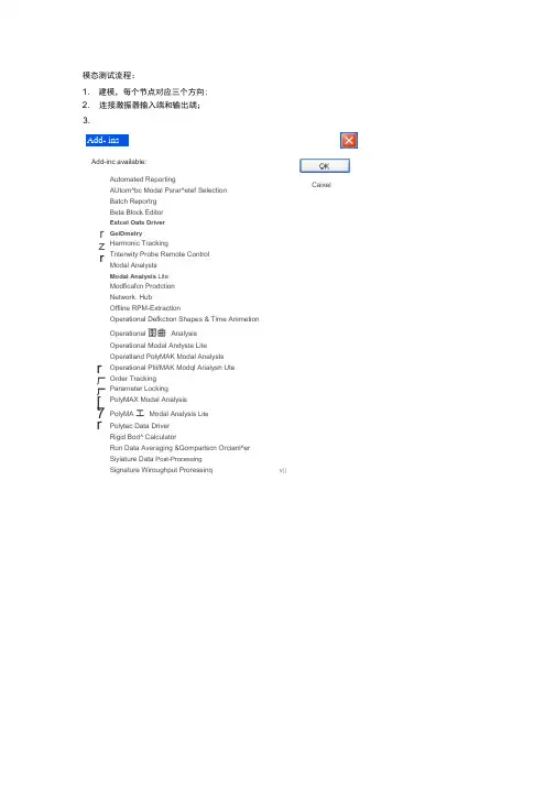
v||模态测试流程: 1. 建模,每个节点对应三个方向;2. 连接激振器输入端和输出端;3. Add- ins Add-inc available: Caixelr z r r 厂 厂 [7 r Automated Reporting AUtom^bc Modal Psrar^etef Selection Batch Reportrg Beta Block EditorEstcel Oats DriverGeiDmetryHarmonic TrackingTnterwity Probe Remote ControlModal AnalystsModal Analysis LiteModficafcn Prodction Network. HubOffline RPM-ExtractlonOperational Defkction Shapes & Time Animetion Operational 函曲 Analysis Operational Modal Andyste Lite Operatland PolyMAK Modal AnalystsOperational Ptil/MAK Modql Arialysh UteOrder Tracking Parameter LockingPolyMAX Modal AnalysisPolyMA 工 Modal Analysis Lite Polytec Data DriverRigid Bod^ CalculatorRun Data Averaging &Gomparlscn Orcianl^er Siyiature Data Post-Processing Signature Wiroughput ProressinqAdd-insAdd-ins available:厂Operational PolyMAX Modal Analysts 厂AOperational PolyMAX Modal Analysis Lite 厂OrderTracking 厂Parameter Locking 疋PolyMAX Modal Analysis 厂Poly MAX Modal Analysis Lite 厂Poly tec Data Driver 厂Rigid Body Calculator 厂Run Data Averaging & Comparison Organizer 厂Si gnatur e D ata Po st-Proce ssing [7 Signature Throughput Processing 厂Sound Diagnosis 厂Sound Intensity Analysis 匝Source Control 厂Structural Remote Control 厂Tec.Manager Hub 厂Time Data ExtractionTime Recording During Spectral Testing 厂Time Signal Calculator 厂Time-Variant Frequency Analysis 厂TPA Component Editing 厂TPA Single Reference 厂User 1 r User 2 厂User 3 I- User 4 厂User 5V建模界面,注意运用局部坐标系。

制动盘模态试验分析作者:上海汇众汽车制造有限公司陈晓鹏模态分析技术是用于对零部件或工程结构系统进行动力学分析的现代化方法和手段,借此可以解决很多工程实际问题。
对零部件进行模态分析有利于优化运动机械的整体性能。
以汽车制动盘为例,制动盘的模态决定着车辆在制动过程中的部分振动、噪声性能,并对制动盘的寿命、异常磨损等产生影响,测量并确定制动盘的模态频率与振型是研究并解决车辆制动引起振动与噪声的重要手段。
本文利用LMS公司有关模态测试软件对我公司某车型前制动盘进行比较完整的模态测量后,得出了制动盘的各种模态特性;并利用测试软件对测试方法进行了简短的分析,给出了在仅仅想得到零部件固有频率的试验要求下可以简化几何模型、减少测量次数,从而达到最快得到试件固有频率的目的。
制动盘模态特性及要求作为高速旋转部件,制动盘具有中心对称特性。
对于制动盘制动摩擦面,其振型主要是沿圆周均匀分布的变形(对于矩坐标系,相同θ角的各点位相相同,沿圆周呈波浪分布)及相同r(在矩坐标系中)具有相同形变(幅值与位相均相同)的变形。
当与制动系统中其他部件组合后,如果某种激励正好位于某一固有频率下,模态被激发,处于共振情形中的这种自身变形会产生强烈的振动与噪音。
前一种模态发生共振的可能性更大。
通常,制动盘处于本文后面所提到的0/4模态占优势,在产品设计与开发阶段要特别注意此类模态的特性。
测量与分析利用LMS TestLab 中的MODAL IMPACT模块可对制动盘进行模态测量。
用弹性绳把制动盘悬挂起来,将由试件与软绳所组成的系统振动的固有频率控制在5Hz以下,就能完全满足测试要求。
制动盘具有中心对称轴,以中心轴为Z轴,建立柱坐标系。
显然,制动盘除Z轴外的其他两方向的刚度比Z轴方向的刚度要大得多,在常规频段振动主要是沿着Z轴方向发生,因此只测定Z轴方向的加速度值即可。
制动盘结构相对较小,质量不大,因此在粘贴传感器时应尽量减小附加质量的影响,为此采用分别在多点激励、测取某一点处的响应的方法进行。
b模态及ODS测试分析在某车轰鸣问题的应用作者:张爱东常辉邓晓龙摘要:本文基于LMS b中的模态测试及ODS分析模块,对某3缸柴油机微车加速过程中的Booming噪声源进行了排查。
通过整改,室内该问题噪声约降低了10分贝,达到可接受的水平。
微车兼有生产工具、生活工具双重功能,在农村、乡镇和城市物流中发挥很好的作用,也决定了其市场的广阔性。
然而人们生活水平不断提高,购买力也随之提升,汽车的价格反而在不断下降,消费者也逐渐脱离了一味对车辆经济性的要求,对安全性、舒适性的要求已经大大提高。
微车绝大多数为中置后驱车辆,很多微车在加速时都存在后桥引起的室内轰鸣声。
尤其对于3缸柴油机微车,由于发动机激励远大于4缸发动机,该问题更为突出,严重影响了其乘座舒适性,引起微车用户的抱怨。
本文通过LMS b中的模态测试分析模块及ODS分析模块,对某3缸柴油机微车加速Booming噪声源进行了排查,通过整改,使该微车乘座舒适性有了较大程度的提高。
1 试验模态及ODS分析方法1.1 试验模态分析试验模态分析根据试验方法可分为两种:(1)正则振型试验法(NMT):用多个激振器对结构同时进行正弦激励,在激励力矢量被调到正比于某一振型时,就可激励出某一个纯模态振型,并直接测试出相应的模态参数(模态频率、模态阻尼、振型)。
该方法结果精度高;但是需要高精度的测试仪器和熟练的测试技能,费时长、成本高。
(2)频响函数法(FRF):此法可只在结构的某一选定点上进行激励,同时在多个选定点上依次测量其响应。
将激励和响应的时域信号,经FFT分析转换成频域信号。
因频响函数是响应与激励谱的复数比,对已建立的频响函数数学模型进行曲线拟合,就可从频响函数求出系统的模态参数,该方法可同时激励出大部分模态,测试时间短,所用仪器设备较简单,测试方便。
1.2 ODS分析ODS(Operational Deflection Shapes,也称为工作变形),是被测试试件在某特定频率、特定转速或特定时间的实际工作变形,描述的是被测试试件在实际工作激励下的受迫振动变形。
LMS 模态分析: 完整解决方案LMS Modal Analysis Techniques内容提要2模态试验分析工具1模态试验目的3模态仿真分析工具2.1分析手段2.2试验手段2.3数采前端3.1结构修改及预测3.2相关性分析3.3预试验4综述X=SourceReceiver•Engine •Rotor •Road•Gearbox & transmission •Turbo machinery •Wheel & tire •Accessories•Environmental sources •...Transfer through the structure•Noise at driver’s & Passenger ears •Steering wheel shake•Rear view mirror vibration•Cabin comfort •Structural integrity •Seat vibration •Cockpit NVH •...System TransferSystem Transfer M o d a l An a l y s i s模态分析9结构固有属性分析9表现为9共振频率9阻尼比9振型目的:9验证产品振动与噪声问题9提高产品耐久性9提高数字模型准确性内容提要2模态试验分析工具1模态试验目的3模态仿真分析工具2.1分析手段2.2试验手段2.3数采前端3.1结构修改及预测3.2相关性分析3.3预试验4综述模态试验工具:数采前端Mobile:移动305306 slave unitAC / DC / BatteryStandard LANSCSI optionalLab / Test Benches:台架310311 slave unitAC or AC / DC /BatteryStandard SCSIOptional LAN316317 slave unitACSCSI or Wide SCSIM01 & M05Autonomy -lowpower consumption:Up to 4 hours oninternal batteriesBroad operatingconditions:-10 C > +55 CVibration / shock:MIL-STD 810F…Potable:便携Modular and scalable for any NVH applicationLMS SCADAS MobileCompact -high channel count low power –wide operating conditionsLMS SCADAS III Extended throughput performance & signal conditioningAny signal condition you would want...Tacho VoltageICP MicrophoneChargeTEDSBridgeDigitalAES/EBUTorsionalAnalog OUTDACModular and scalable for any NVH application4 4 4 4 419212060408Number of channels per frameSC316SC310SC305SCM05SCM01内容提要2模态试验分析工具1模态试验目的3模态仿真分析工具2.1分析手段2.2试验手段2.3数采前端3.1结构修改及预测3.2相关性分析3.3预试验4综述模态试验方法:锤激法Modal impact guides the operator through the test setupand sets up the test for him System suggested parametersTrigger settingsWindow parametersAcquisition bandwidthProductive impact testingAudio feedbackAuto-reject overloadsAuto-reject double impactsAuto-accept good averagesAuto-increment hammer ID模态试验方法: MIMO 激振器法Random; MIMO Sine Multichannel FRF testingMultiple parallel measurement functions Fixed or user-defined display layouts Clear measurement status indication Detailed overload information Level indicatorsThe online shaker decorrelatio n check makes sure meaningful FRF resultsare measuredFor those cases were random fails…Trimmed body modal testing (Vibro-)acoustic modal testing(Reciprocal) noise transfer functions Dynamic mount stiffness identification Non-linearity analysisThe benefits of sine excitation in the measurement time of burst模态试验方法: 纯模态法Productive and flexible online monitoringgives confidencein the measureddata Pre-test function inspectionTimeDriving point FRFs, coherencesForce autopowersPCA (shaker decorrelation check)…Multichannel FRF testingMultiple parallel measurement functionsFixed or user-defined display layoutsClear measurement status indicationDetailed overload informationLevel indicators模态试验方法: 工作模态法Animating data directly after the measurement is a powerfuldata validationtool Dedicated processing of time dataExponential window for correct dampingestimates (<> hanning cannot be corrected)Batch processing of multiple measurementsCrosspower/ correlation function previewOperational modal analysisDetermine dynamic properties in operationResonant frequenciesDamping valuesMode shapesMulti-run modal for increased mode shapequality and reliability内容提要2模态试验分析工具1模态试验目的3模态仿真分析工具2.1分析手段2.2试验手段2.3数采前端3.1结构修改及预测3.2相关性分析3.3预试验4综述模态分析工具: LSCE 法Automatic scrolling FRF synthesis reduces the time to validate the modal modelOperator guidance makes modal analysis faster and easier then ever beforeFast and easy modal parameter estimationOnly 3 steps to get to mode shapes Improved ‘industry-standard’LSCE Built for large datasetsFull traceability –back to used transducerExtensive modal validation toolsGeometry based FRF synthesis Automatic scrolling FRF synthesis Mode Correlation & ComplexityAutomatic visual comparison of 2 modesAnimation & Color displaysRule-based methodNot affected by ability of human mind to treat informationHigh accuracy on pole selection Reduce uncertaintyLMS PolyMAX results in crystal-clearstabilizationdiagrams, leading to user-independent, high quality modes On complex data, traditional techniques often result in difficult to interpret stabilization diagramsExtremely clear stabilizationFast & Easy pole selection User-independent results More & higher quality modes “General purpose”methodSingle broadband analysis High & low damping Noisy dataBuilt for large & complex structures Trimmed body, powertrain assembly, … Aircraft, spacecraft, …. Turbomachinery, civil structures, …PolyMAX& AMPS generate automatically user-independent resultsExtremely clear stabilizationFast & Easy pole selection User-independent results More & higher quality modes “General purpose”methodSingle broadband analysis High & low damping Noisy dataBuilt for large & complex structuresTrimmed body, powertrain assembly, … Aircraft, spacecraft, ….Turbomachinery, civil structures, …Operational deflection shapes provides insights in vibration and acoustic problemsBatch processing of multiple measurement is fast and easy一步到位的参数提取工具Automatic data retrievalAnalysis data sets build and expand whilethe measurements proceed –no manual index tableClear overview of all FRFs in one tableMulti-run modal analysisCompensation of frequency shifts betweenruns due to mass loading or temperature effectsAutomatic merging of modes from differentrunsConsistent, less complex mode shapesMulti-run modalresults in higher quality mode shapes, making inconsistent data consistentAll measured functions at a glance in a single table ready to analyzeAMPS -rule-based methodNot affected by ability of human mind to treat informationHigh accuracy on pole selection Reduce uncertaintyAll physical poles selected at a glance in stabilization diagramLMS b modification prediction Efficient troubleshootinglet the tool do the repetitive work faster and more consistenttuned absorbers provide a shortcut solution to solve a probem in a late product design stageEvaluate structural design changes without repeated testingQuickly find a vibration patch Evaluate design alternative Move resonant frequenciesMass, spring, damper, tuned absorberModal modification predictionGraphical definition of modificationsVisualization of modifications on geometry Automatic tuning of tuned absorber Automatic synthesis of base and modifiedFRFsTraceability of modificationsA complete solution for structural testingTest Preparation GeometryTest ExecutionModal impactSpectral acquisitionMIMO sine testingAnalysisModal analysisoperational modal analysisReportingDesktopOperational deflection shapestime animationDocumentationOperational testingMaximal data consistency in minimal timeMultiple parallel measurement functions reduces the amount of measurement runs and increases data consistencySCM05: productive testing, on the road and in thelabMobile measurement supportMobile frontend: SCM05,embedded dual tachoembedded dual DAC for lab testing Direct throughput to TDF Remote controlOnline/offline data validation includingreplayMultiple parallel measurement functionsOnline analysis: spectra, autopowers,crosspowers, octaves, …Throughput dataMaximal data consistency in minimal time7A NEWLMS –TPA: 结构传递路径分析LMS 传递路径分析是一非常高效的工具,可以让我们有效且直接地进行结构及声学能量分析来找到激励源与研究目标之间的关系对振动噪声传递路径进行评价并量化目标是确认需要修改的路径成分,并选择更好的元件参数和设计,以优化NVH性能目标响应频谱第i 条传递路径上,激励与目标之间的传递函数第i 条传递路径上的输入力谱传递路径分析是基于频响函数及作用于传递路径点上的作用力。

LMS b锤击法模态测试流程 比利时LMS国际公司北京代表处LMS Test. Lab锤击法模态测试及分析的流程在软件窗口底部以工作表形式表示,按照每一个工作表依次进行即可,如下图示。
1Documentation――可以进行备忘录,测试图片等需要记录的文字或图片的输入,作为测试工作的辅助记录,如下图示。
2Geometry――创建几何(参见创建几何步骤说明)3Channel setup――通道设置,在该选项卡中可进行数采前端对应通道的设置,如定义传感器名称,传感器灵敏度等操作。
4Calibration――对传感器进行标定5Impact scope――锤击示波,用来确定各通道量程6Impact setup――锤击设置,设置触发级、带宽、窗以及激励点选择7Measure――设置完成后进行测试以下为进行模态测试的流程。
步骤一:通道设置(Channel setup)假设已创建好了模型,传感器已布置完成,数采前端已连接完成。
通道设置窗口如下图示,在锤击法试验中,首先将力锤输入的通道定义为参考通道,其他为传感器对应的通道1——选取测试通道2——定义参考通道,通常为力锤输入的通道3——依次在ChannelGroupld中定义传感器测量类型(对加速度计和力锤则选vibration),在point中定义测点名称(也可对应为几何模型上的节点名,见后),在Direction中设置测点所测振动的方向,InputMode中设置传感器类型(通常为ICP,若为应变则选Bridge,若为位移则选Vlltage DC),在Measured Quantity中定义测量量(加速度、力、位移等),在Electrical Unit中定义输入量的单位,通常均为mv.另外若已经确定传感器的灵敏度则可在Actual Sensitivity中直接输入灵敏度值,否则可在Calibration工作表中进行标定。
注:通道设置中测点名称使用几何模型名称的方法步骤二:锤击示波(Impact scope)在该工作表中可设置测试的量程范围,以保证得到更精确的测试结果。
LMS b中文操作指南比利时LMS国际公司北京代表处2009年 6月内容¾ Desktop桌面操作¾ Geometry几何建模¾ Signature信号特征测试分析¾ Impact锤击法模态测试¾ Spectral Testing谱分析¾ Modal Analysis模态分析¾ Modification Prediction模态修改预测¾ ODS工作变形分析¾ OMA运行模态分析LMS b中文操作指南— Desktop桌面操作比利时LMS国际公司北京代表处2009年2月LMS b中文操作指南— Desktop桌面操作目录1.开始 (2)2.浏览数据 (3)3.显示数据 (4)3.1.测试的数据 (4)3.2.图形拷贝 (8)3.3.几何图形显示 (8)4.数据调理 (10)5.搜索功能 (11)6.Documentation 界面 (13)6.1.添加附件 (13)6.2.添加模板 (14)6.3.添加用户属性 (15)7.导入外部数据 (17)1. 开始¾ 启动 LMS b Desktop 从 开始菜单 Æ 所有程序 Æ LMS b 9AÆ Desktop 或者通过 桌面的快捷图标软件打开后,通过底部的导航条,可以看到两个界面:Documentation 和 Navigator 。
默认会打开一个空白的Project ,软件激活“Navigator”页面中的“Data Viewing”子页面。
可以浏览数据,图形显示数据。
页面在LMS b 资源管理器中可以看到Project ,另外还有:My Computer: 资源管理器最后一个项目。
可以浏览您电脑中的数据。
My Links: 此处可以链接常用Project 的快捷方式,首先从“My Computer”找到Project ,右键单击Copy ,然后到 “My Links”右键单击Paste as link 。


LMS b中文操作指南— OMA运行模态分析比利时LMS国际公司北京代表处2009年2月LMS b中文操作指南— OMA运行模态分析目录第一步,几何模型的建立 (3)1.更改软件界面设置及项目文件名: (3)2.建立几何模型 (3)第二步,工作模态分析 (4)1.进行互功率谱计算 (4)2.选择参与工作模态分析的互谱数据 (5)3.进行工作模态参数识别 (6)第三步,工作模态分析结果的验证 (7)第一步,几何模型的建立1.更改软件界面设置及项目文件名:¾打开 b Desktop软件界面:¾进入主菜单 Tools‐>Add‐ins界面,分别勾选 Geometry, Operational Modal Analysis, Operational PolyMax Modal Analysis三个 Add‐in。
¾进入主菜单 Tool‐>Workbook Configuration…,为使用方便,将导航栏顺序调整为如下形式:¾新建一个 Project,另存更改项目名,如 ”XXX OMA”。
主菜单 File‐>Save as,定义项目名,保存。
¾更改 Section的名称,在快捷键中选择 a|e,更改 Section的名称为某工况名称,如”run1”2.建立几何模型¾点击导航栏中的 Geometry界面:¾在 Components界面中建立一个子结构,如”Comp”;点击 Accept Table。
¾进入 Nodes界面,在 Name栏填入各测试点的序号或名称,如1,2,3,…,在 X(m),Y(m),Z(m)中分别填入各测试点所对应的几何坐标,点击 Accept Table;¾注意:”Component:Node”所组成的点标识必须与在Spectral或Signature测试中通道设置中所设定的 PointId 中的通道标识名相同,否则需要更改测试数据的PointId。

LMS b 在超重训练设备模态分析试验中的运用章 剑 王 翔 王吉成中国直升机设计研究所 九室 33001摘要:本文介绍了运用Lms b 软件的模态分析为试验手段来诊断航天员超重训练设备所存在的故障,通过模态分析试验研究表明系统刚度变化对系统自振频率的影响,动力系统轴承齿轮间摩损的间隙以及环境因数如地基沉降对系统频率的影响等。
关键词: Lms b 、超重训练设备、模态分析、刚度 1 前言航天员超重训练设备是一台以大型载人离心机为主体,能够模拟飞船上升段和返回段超重过载环境以及其他超重过载环境的综合训练设备。
为保障超重训练设备各系统均处于良好协调运转状态,开展了设备全面诊断维修、系统升级和保养等工作。
通过研究超重训练设备在不同条件下受到激励作用后的共振情况,对航天员超重训练设备在维修前进行了模态试验,通过试验结果分析找出所存在的故障,为超重训练设备结构系统的振动特性分析、振动故障诊断和预报以及结构动力特性的优化设计维修提供了依据。
经过维修后再次对航天员超重训练设备进行模态分析与关键旋转部件进行振动检测分析,将维修前后的动力学特性数据进行分析比较,评价维修后超重训练设备的动力特性。
2 试验模态分析的基本原理模态分析的理论基础是在机械阻抗与导纳的概念上发展起来的,近十多年来,模态分析理论吸取了振动理论、信号分析、数据处理、数理统计及自动控制理论中的有关内容,结合自身内容的发展,形成了一套独特的理论,为模态分析即参数识别技术的发展奠定了理论基础。
自动控制理论中的传递函数(或频率响应函数)概念的引入,对模态分析理论的发展起了很大的推进作用。
通过传递函数,我们可以得到机械结构振动的固有频率以及机械结构各部分的响应变形,而固有频率和振型一起构成机械的振动模态。
人们把通过测量求取振动模态并由此进一步分析机械动态特性的方法称为模态分析。
一般结构系统可以离散为一种具有N 个自由度的线弹系统,其运动微分方程为:[]{}[]{}[]{}{()}M xC x K x f t ++=′′′′′′ٛٛٛٛٛٛ (1) 式中质量、阻尼、刚度矩阵[M]、[C]、[K]为实对称矩阵,[M]正定、[C]、[K]正定或半正定。
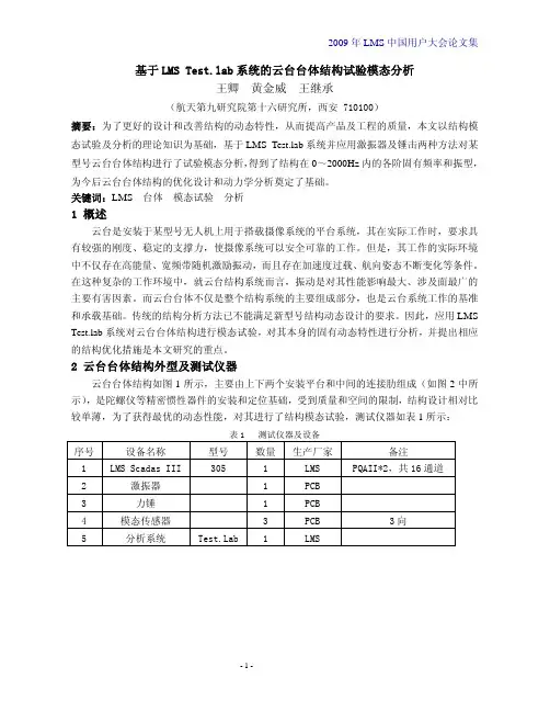
基于LMS b系统的云台台体结构试验模态分析王卿 黄金威 王继承(航天第九研究院第十六研究所,西安 710100)摘要:为了更好的设计和改善结构的动态特性,从而提高产品及工程的质量,本文以结构模态试验及分析的理论知识为基础,基于LMS b系统并应用激振器及锤击两种方法对某型号云台台体结构进行了试验模态分析,得到了结构在0~2000Hz内的各阶固有频率和振型,为今后云台台体结构的优化设计和动力学分析奠定了基础。
关键词:LMS 台体模态试验分析1 概述云台是安装于某型号无人机上用于搭载摄像系统的平台系统,其在实际工作时,要求具有较强的刚度、稳定的支撑力,使摄像系统可以安全可靠的工作。
但是,其工作的实际环境中不仅存在高能量、宽频带随机激励振动,而且存在加速度过载、航向姿态不断变化等条件。
在这种复杂的工作环境中,就云台结构系统而言,振动是对其性能影响最大、涉及面最广的主要有害因素。
而云台台体不仅是整个结构系统的主要组成部分,也是云台系统工作的基准和承载基础。
传统的结构分析方法已不能满足新型号结构动态设计的要求。
因此,应用LMS b系统对云台台体结构进行模态试验,对其本身的固有动态特性进行分析,并提出相应的结构优化措施是本文研究的重点。
2 云台台体结构外型及测试仪器云台台体结构如图1所示,主要由上下两个安装平台和中间的连接肋组成(如图2中所示),是陀螺仪等精密惯性器件的安装和定位基础,受到质量和空间的限制,结构设计相对比较单薄,为了获得最优的动态性能,对其进行了结构模态试验,测试仪器如表1所示:表1 测试仪器及设备序号 设备名称 型号 数量生产厂家备注1 LMS Scadas III 305 1 LMS PQAII*2,共16通道2 激振器 1 PCB3 力锤 1 PCB4 模态传感器 3 PCB 3向5 分析系统 b 1 LMS图1 云台台体结构三维示意图3 试验模态分析原理概述试验模态分析又称模态分析的试验过程,是理论模态分析的逆过程。
LMS b中文操作指南比利时LMS国际公司北京代表处2009年7月内容¾ Desktop桌面操作¾ Signature信号特征测试分析¾ Spectral Testing谱分析¾ Geometry几何建模¾ ODS工作变形分析LMS b中文操作指南— Desktop桌面操作比利时LMS国际公司北京代表处2009年2月LMS b中文操作指南— Desktop桌面操作目录1.开始 (2)2.浏览数据 (3)3.显示数据 (4)3.1.测试的数据 (4)3.2.图形拷贝 (8)3.3.几何图形显示 (8)4.数据调理 (10)5.搜索功能 (11)6.Documentation 界面 (13)6.1.添加附件 (13)6.2.添加模板 (14)6.3.添加用户属性 (15)7.导入外部数据 (17)1. 开始¾ 启动 LMS b Desktop 从 开始菜单 Æ 所有程序 Æ LMS b 9AÆ Desktop 或者通过 桌面的快捷图标软件打开后,通过底部的导航条,可以看到两个界面:Documentation 和 Navigator 。
默认会打开一个空白的Project ,软件激活“Navigator”页面中的“Data Viewing”子页面。
可以浏览数据,图形显示数据。
页面在LMS b 资源管理器中可以看到Project ,另外还有:My Computer: 资源管理器最后一个项目。
可以浏览您电脑中的数据。
My Links: 此处可以链接常用Project 的快捷方式,首先从“My Computer”找到Project ,右键单击Copy ,然后到 “My Links”右键单击Paste as link 。
Search Results: LMS b 软件可以进行搜索,搜索的结果放在此处。
Input Basket: 暂时存放准备作处理的数据。
LMS b中文操作指南比利时LMS国际公司北京代表处2009年 6月内容¾ Desktop桌面操作¾ Geometry几何建模¾ Signature信号特征测试分析¾ Impact锤击法模态测试¾ Spectral Testing谱分析¾ Modal Analysis模态分析¾ Modification Prediction模态修改预测¾ ODS工作变形分析¾ OMA运行模态分析LMS b中文操作指南— Desktop桌面操作比利时LMS国际公司北京代表处2009年2月LMS b中文操作指南— Desktop桌面操作目录1.开始 (2)2.浏览数据 (3)3.显示数据 (4)3.1.测试的数据 (4)3.2.图形拷贝 (8)3.3.几何图形显示 (8)4.数据调理 (10)5.搜索功能 (11)6.Documentation 界面 (13)6.1.添加附件 (13)6.2.添加模板 (14)6.3.添加用户属性 (15)7.导入外部数据 (17)1. 开始¾ 启动 LMS b Desktop 从 开始菜单 Æ 所有程序 Æ LMS b 9AÆ Desktop 或者通过 桌面的快捷图标软件打开后,通过底部的导航条,可以看到两个界面:Documentation 和 Navigator 。
默认会打开一个空白的Project ,软件激活“Navigator”页面中的“Data Viewing”子页面。
可以浏览数据,图形显示数据。
页面在LMS b 资源管理器中可以看到Project ,另外还有:My Computer: 资源管理器最后一个项目。
可以浏览您电脑中的数据。
My Links: 此处可以链接常用Project 的快捷方式,首先从“My Computer”找到Project ,右键单击Copy ,然后到 “My Links”右键单击Paste as link 。
LMS公司推出LMS TestLab第七版LMS b第七版的推出是一个新的里程碑,提高了振动噪声试验效率。
LMS b 第七版集成了600多项新功能和改进,适用于各种试验任务。
此外,LMS b第七版还新增了移动测试功能,为用户提供适用于车内或现场试验的最佳便携性,以及直观的系统交互性。
LMS b第七版,与紧凑可靠的LMS SCADAS Mobile前端完美结合,可支持单人数据采集,同时提供灵活的快捷键和友好的操作界面。
新版本另一项特点是提供世界上首个自动化模态分析解决方案,具有最佳的模态一致性和最短的分析时间。
自动化模态参数选择(AMPS)可以在10分钟内建立非常复杂或高阻尼结构的高质量模态模型,而且不受操作者人为影响。
LMS b第七版利用创新性技术和工作流程驱动的方法,提高了从标定试验到系统级问题诊断整个开发流程中每个阶段的工作效率。
LMS b第七版新功能:∙新的移动测试用户界面,为车载试验提供最理想的便携性∙完全支持LMS SCADAS Mobile,适用于谱和实时特征信号采集,锤击模态试验和实时倍频程试验∙可以灵活选择在线、嵌入和离线三种处理方式∙离线RPM提取,如果没有测量转速信号也能够精确捕捉RPM信号,用于振动或声学阶次分析∙自动化模态参数选择(AMPS)——精确、可靠、快速,且不受操作者影响∙稳态和瞬态阵列——用于声源定位——形成了以特有的声聚焦为核心的一整套声源定位方法∙冲击响应合成和试验序列自动化——支持无人监控的长时间的且具有多种振动控制的鉴定试验LMS b Rotating Machinery旋转机械分析第七版——专为移动测试设计的用户界面在驾驶员位置进行试验为了有效地进行道路试验,试验操作者需要能够单手操作的解决方案,同时能够简单地实时监测试验进度和状态信息。
为了满足这种特定的车内测试需求,LMS b第七版新推出了特定的用户界面,并与专为现场测试而开发的LMS SCADAS Mobile数采前端结合进行试验。
基于b的车身模态有限元分析及试验验证王永利赵永宏周文超一汽技术中心摘要:车身模态分析就是研究车身振动特性的主要方法,其具体研究方式可分为试验模态分析和有限元模态分析两种方法。
基于有限元方法的模态分析,由于在建模过程中引进了一系列人为假设,因而导致了计算结果存在误差。
而试验模态分析是建立在试验基础上,所得到的动态特征参数则比较真实地反映了物理模型的的动力学特性。
本文分别用两种方法对乘用车白车身的模态进行分析计算,并对两种方法计算的结果进行对比验证。
进而为模态灵敏度分析、模态修正以及FEM校正等工作奠定了基础。
关键词:白车身模态分析试验模态有限元模态模态验证1.前言车辆在行驶过程中,车身结构在各种振动源的激励下会产生振动,如发动机运转、路面不平以及高速行驶时风力引起的振动等。
如果这些振源的激励接近车身整体或局部的固有频率,便会发生共振现象,产生剧烈振动和噪声,甚至造成结构破坏,为提高汽车的安全性、舒适性和可靠性,就必须对车身的振动特性进行分析,通过结构设计避免开各种振源的激励频率。
车身的模态分析技术就是解决车身振动问题最有效、最经济的方法。
车身的模态分析技术分为有限元模态分析和试验模态分析。
这两个方面的运用和发展相辅相成,能有效车身结构的振动问题。
特别是计算机技术的高速发展,有限元分析技术成熟的应用,在车身概念设计间段就可以对车身的振动特性进行详细的分析预测,对结构的设计更改提供可靠的数据,这样大大缩短了汽车的开发周期,降低开发成本。
有限元模型的建立,在边界条件的处理及力学模型的简化上,往往与实际结构相差较大,这样便会导致有限元模型的计算结果不可靠,失去实用价值。
用试验模态分析的模态参数对有限元模态分析的结果进行验证并修正有限元模型,使其更能符合实际从而提高有限元分析的精度。
本文对乘用车白车身的模态首先进行有限元分析,然后对对白车身样车进行试验模态分析,用试验模态参数对有限元模型计算结果进行对比分析验证。
LMS b中文操作指南— Modal Analysis 模态分析比利时LMS国际公司北京代表处2009年2月LMS b中文操作指南— Modal Analysis 模态分析目录第一步,打开modal analysis 软件模块 (3)第二步,Modal Data Selection 模态数据选择 (4)第三步,模态分析(Time MDOF or PolyMAX) (7)1.Band 选择分析带宽 (7)2.Stabilization 选择极点 (9)3.Shapes 计算模态振型 (12)第四步,模态综合Modal Synthesis (14)第五步,模态验证 Modal Validation (16)附录关于阻尼比的说明 (21)第一步,打开modal analysis 软件模块打开modal analysis 主要有两种方法,如果客户是Desktop Advanced ,你可以直接通过软件上面的Tools,点击Add-ins,勾选modal analysis,点击ok就可以在Impact Testing或者 Spectral Testing中直接打开该模块;如果客户是 Desktop Standard,那么你可以直接在程序中打开modal analysis 模块。
第二步,Modal Data Selection 模态数据选择这个界面的功能就是进行FRF数据的选择,该界面里所有的按钮和菜单都是为了方便操作者进行数据选择,可以按照操作者的意愿方便地选择需要的数据,剔除不需要的数据。
软件提供了两种数据选择:1、 Active Section这种方法就是从你目前活动的section中选择数据。
LMS软件为了方便客户灵活选择,这里又有三种方法。
(1) Measurement run软件默认的就是第一种方法,并且默认选择All,会默认选择该section中所有的FRF函数。
当然客户可以感觉自己的需求选择其中的某一个Run。