studer_OnAir_V3_2_sw[1]
- 格式:pdf
- 大小:132.27 KB
- 文档页数:1
V3.0.8点播系统的PFACE.CONF文件的配置说明:以下为具体的效果器配置参数:KTV800II代配置:effe_dev_baud 38400effe_dev_type k8002KTV600配置:effe_dev_baud 19200effe_dev_type k6000HK168配置:effe_dev_type hk168 (HK168无速率问题)KTV600 + HK168配置:effe_dev_baud 19200effe_dev_type hk168以下为具体的指针设备配置:键盘设备的指定方法:keyb_dev_name key_boardkeyb_dev_type dev_event鼠标设备的指定方法:mice_dev_name rel_mousemice_dev_type dev_event触摸设备的指定方法:mice_dev_name abs_touchmice_dev_type abs_touch摇杆设备的指定方法:jstk_dev_name joy_stickjstk_dev_type dev_event普通鼠标的配置:mice_dev_type ps2_mousemice_dev_name /dev/mouse三鹰USB红外屏的配置:mice_dev_type hid_mtusbmice_dev_name /dev/input/touch0三鹰PS2红外屏的配置:mice_dev_type ps2_mtps2mice_dev_name /dev/mouse凌云PS2红外屏的配置:mice_dev_type ps2_l2ps2mice_dev_name /dev/mouse吉瑞USB声波屏的配置:mice_dev_type hid_grusbmice_dev_name /dev/input/touch0吉瑞串口声波屏的配置:mice_dev_type cau_gr232mice_dev_name /dev/ttyS1USB触摸屏自动识别参数:(无法自动识别鼠标口触摸屏)mice_dev_name dev_eventmice_dev_type dev_event鼠标口先歌红外屏配置:mice_dev_name /dev/psauxmice_dev_type ps2_xgps2主要配置参数:firstpageindex :第一页页码号,可选值0/1facelock_songs_max :锁房后,保留歌曲数,可选值[0-50],默认0,全部清除,如果锁房时不清歌,或者,锁房后是否清歌由管理系统定的话,此值设置为50,即不清歌bsamesong :同一首歌曲是否可以重复点选0不允许,1允许,默认0songtrack_mode :歌曲间音轨跟随模式,0伴唱,1原唱,2跟前一首相同,默认1reboot_songclean :重启后,已选列表是否清除,0不清除,1清除默认0screensave_delay :多少没有动作秒后进入屏保默认60screensave_space :图片更替时间间隔默认10screensave_style :屏保方式,0不进入屏保(screensave_delay将无效),默认01强制进入屏保,2自动识别物理设备rocksong_hide :是否隐藏劲歌0不隐藏,1隐藏默认1CfmNext :切歌是否需要确认0不需要确认,1需要确认默认0winemode :酒水模式haimei/cando 默认haimeiVOLSCALE :调节音乐音量时,调节的刻度默认10sw_DevPath :三相屏的设备名默认/dev/usb/tts/0rpmode :随机播放模式,0根据pick.txt文件顺序播放,1从pick.txt文件随机选去文件播放默认1cardvolume :解压卡的初始化音量,默认0>0,将解压卡音量设置为此值,界面上调节音量时,调效果器的音量=0, 解压卡音量由系统设定,界面上调节音量时,调解压卡的音量effectvolume :效果器初始化音量[0-36] 默认24bSCMood 是否使用声卡气氛,0:不开启/1:开启.cpboard_logpwd 进入墙板学习的密码默认68473cpeffer_logpwd 进入调音台的密码默认68473cprockd_logpwd 劲歌的密码默认68473cprname_logpwd 进入包厢名设置的密码默认68473lightmod_style 灯光控制方式: 0,效果控制,直接控制灯,默认值0=0的时候,trad_lamp_state、pop_lamp_state、rock_lamp_state、bar_lamp_state值无效,使用灯光效果=1 的时候,trad_lamp_state、pop_lamp_state、rock_lamp_state、bar_lamp_state值有效lighteffe_val1 第1个灯光效果的初始值,当lightmod_style = 0 时生效,默认值1lighteffe_val2 第2个灯光效果的初始值,当lightmod_style = 0 时生效,默认值4lighteffe_val3 第3个灯光效果的初始值,当lightmod_style = 0 时生效,默认值8lighteffe_val4 第4个灯光效果的初始值,当lightmod_style = 0 时生效,默认值48bWine 是否开放酒水小吃功能,0:不开放,1:开放,默认值为1bMiss 是否开放小姐管理功能,0:不开放,1:开放,默认值为1bBC 是否开放多节目源功能,0:不开放,1:开放,默认值为1bLight 是否开放灯光功能,0:不开放,1:开放,默认值为1bTone 语调是否可以调节,0:不可调节,1:可调节,默认值为1effect_argument{hk168_default_musV ol HK168默认的音量默认65effect_autosel 效果是否自动跟随歌曲默认0 不跟随enable_trad_lamp 传统是否有灯光效果默认不可用trad_lamp_state 传统的灯光效果默认1enable_pop_lamp 流行是否有灯光效果默认不可用pop_lamp_state 流行的灯光效果默认4enable_rock_lamp 劲歌是否有灯光效果默认不可用rock_lamp_state 劲歌的灯光效果默认8enable_bar_lamp 酒吧是否有灯光效果默认不可用bar_lamp_state 酒吧的灯光效果默认48enable_rand_lamp 是否开启随机播放灯光0不开启/1开启rand_lamp_state 随机播放时,开启哪些灯}主界面按钮位置,当mm_visible_item = 0 时,下面3个参数无效mainmenu_aspect{mm_visible_item0 歌曲点播按钮是否可见,1,可见,0不可见mm_enable_item0 歌曲点播按钮是否起作用,1,按下有作用,0按下无作用mm_x_item0 歌曲点播按钮的X轴坐标默认:190mm_y_item0 歌曲点播按钮的Y轴坐标默认:170mm_visible_item1 酒水小吃按钮是否可见,1,可见,0不可见mm_enable_item1 酒水小吃按钮是否起作用,1,按下有作用,0按下无作用mm_x_item1 酒水小吃按钮的X轴坐标默认值368mm_y_item1 酒水小吃按钮的Y轴坐标默认:170mm_visible_item2 结帐查询按钮是否可见,1,可见,0不可见mm_enable_item2 结帐查询按钮是否起作用,1,按下有作用,0按下无作用mm_x_item2 结帐查询按钮的X轴坐标默认:544mm_y_item2 结帐查询按钮的Y轴坐标默认:170mm_visible_item3 多节目源按钮是否可见,1,可见,0不可见mm_enable_item3 多节目源按钮是否起作用,1,按下有作用,0按下无作用mm_x_item3 多节目源按钮的X轴坐标默认:722mm_y_item3 多节目源按钮的Y轴坐标默认:170mm_visible_item4 公主刷卡按钮是否可见,1,可见,0不可见mm_enable_item4 公主刷卡按钮是否起作用,1,按下有作用,0按下无作用mm_x_item4 公主刷卡按钮的X轴坐标默认:255mm_y_item4 公主刷卡按钮的Y轴坐标默认:400mm_visible_item5 影视欣赏按钮是否可见,1,可见,0不可见mm_enable_item5 影视欣赏按钮是否起作用,1,按下有作用,0按下无作用mm_x_item5 影视欣赏按钮的X轴坐标默认:462mm_y_item5 影视欣赏按钮的Y轴坐标默认:400mm_visible_item6 模特花蓝按钮是否可见,1,可见,0不可见mm_enable_item6 模特花蓝按钮是否起作用,1,按下有作用,0按下无作用mm_x_item6 模特花蓝按钮的X轴坐标默认:640mm_y_item6 模特花蓝按钮的Y轴坐标默认:400}bcch{ch1 大厅转播第1路名称无默认值,必须指定,不指定时,此路无效ch2 大厅转播第2路名称无默认值,必须指定,不指定时,此路无效ch3 大厅转播第3路名称无默认值,必须指定,不指定时,此路无效ch4 大厅转播第4路名称无默认值,必须指定,不指定时,此路无效ch5 大厅转播第5路名称无默认值,必须指定,不指定时,此路无效ch6 大厅转播第6路名称无默认值,必须指定,不指定时,此路无效ch7 大厅转播第7路名称无默认值,必须指定,不指定时,此路无效ch8 大厅转播第8路名称无默认值,必须指定,不指定时,此路无效ch9 大厅转播第9路名称无默认值,必须指定,不指定时,此路无效ch10 大厅转播第10路名称无默认值,必须指定,不指定时,此路无效ch11 大厅转播第11路名称无默认值,必须指定,不指定时,此路无效ch12 大厅转播第12路名称无默认值,必须指定,不指定时,此路无效ch13 大厅转播第13路名称无默认值,必须指定,不指定时,此路无效ch14 大厅转播第14路名称无默认值,必须指定,不指定时,此路无效ch15 大厅转播第15路名称无默认值,必须指定,不指定时,此路无效(设置数值范围tv01-tv06)volbase1 大厅转播第1路音量默认值50volbase2 大厅转播第2路音量默认值50volbase3 大厅转播第3路音量默认值50volbase4 大厅转播第4路音量默认值50volbase5 大厅转播第5路音量默认值50volbase6 大厅转播第6路音量默认值50volbase7 大厅转播第7路音量默认值50volbase8 大厅转播第8路音量默认值50volbase9 大厅转播第9路音量默认值50volbase10 大厅转播第10路音量默认值50volbase11 大厅转播第11路音量默认值50volbase12 大厅转播第12路音量默认值50volbase13 大厅转播第13路音量默认值50volbase14 大厅转播第14路音量默认值50volbase15 大厅转播第15路音量默认值50}双点配置:(范例)MAC //附机MAC{play_eth_addr 00.00.00.00.00.00 //主机MAC,相同部分的配置不要写}特别说明:pface.conf配置文件里面不能写相关注释。

第17章STemWin外语支持本期教程的主要内容来自官方的用户手册,我这里专门的把这里的内容整理出一章主要是通过一些实例来帮助大家理解。
阿拉伯语、泰语或汉语等外语文本一般含有emWin标准字体以外的字符。
本章将介绍一些基本知识,比如定义全球所有可用字符的Unicode标准,以及UTF-8编码方案,emWin 使用该方案来解码以Unicode字符编写的文本。
同时还将说明如何启用阿拉伯语支持,以及如何采用Shift-JIS(日本工业标准)编码方案来显示文本。
17. 1 Unicode17. 2 阿拉伯语支持17. 3 泰语支持17. 4 Shift JIS支持17. 5 总结17.1Unicode关于unicode的编码方面的知识在百度百科或者wiki百科上面有详尽的介绍,初学的一定要认真的看一下,了解这方面的知识对于以后学习大有裨益。
这里我们主要的介绍一下UTF-8。
17.1.1UTF-8 编码方案Unicode是国际组织制定的可以容纳世界上所有文字和符号的字符编码方案。
Unicode用数字0-0x10FFFF来映射这些字符,最多可以容纳1114112个字符,或者说有1114112个码位。
码位就是可以分配给字符的数字。
UTF-8,UTF-16,UTF-32都是将数字转换到程序数据的编码方案。
ISO/IEC 10646-1定义了一种称为通用字符集(UCS)的多八位字符集,收入了全球大多数文字系统。
然而,多八位字符并不兼容许多现有的应用程序和协议,因此就扩展出了一些各有特色的UCS转换格式(UTF)。
举个例子帮助大家理解,在Unicode中,汉字“字”对应的数字是23383(十进制),十六进制表示为0x5B57。
在Unicode中,我们有很多方式将数字23383表示成程序中的数据,包括:UTF-8,UTF-16,UTF-32。
UTF是“UCS Transformation Format”的缩写,可以翻译成Unicode字符集转换格式,即怎样将Unicode定义的数字转换成程序数据。
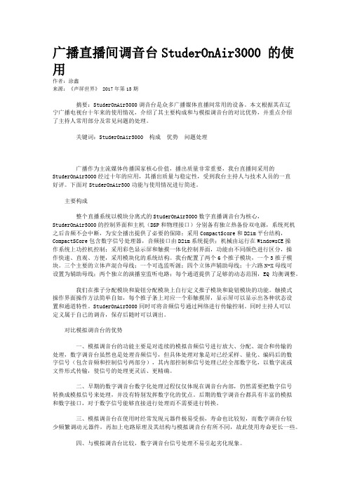
广播直播间调音台StuderOnAir3000 的使用作者:涂鑫来源:《声屏世界》 2017年第13期摘要:StuderOnAir3000调音台是众多广播媒体直播间常用的设备。
本文根据其在辽宁广播电视台十年来的使用情况,介绍了其主要构成和与模拟调音台的对比优势,并重点介绍了主持人常用部分及常见问题的处理。
关键词:StuderOnAir3000 构成优势问题处理广播作为主流媒体传播国家核心价值,播出质量非常重要,我台直播间采用的StuderOnAir3000经过十年的应用,其播出质量与稳定性,受到我台主持人与技术人员的一直好评。
下面对StuderOnAir300功能与使用情况进行简述。
主要构成整个直播系统以模块分离式的StuderOnAir3000数字直播调音台为核心,StuderOnAir3000的控制界面和主机(DSP和物理接口)分别备有独立热备份双电源,系统死机之后音频不会中断,为安全播出提供了必要的保障;采用CompactScore和D21m平台结构,CompactSCore包含数字信号处理器,音频接口由D21m系统提供;机械由运行在WindowsCE操作系统上功控机控制;采用彩色显示屏和触摸一体化控制界面,功能由不同颜色进行区分,操作快速、直观、方便,采用模块化的系统结构。
我台配置了两个6个推子模块,一个3推子模块。
三个主要的立体声混合母线;一个可选监听源;四个立体声辅助母线;十六路N-X母线可设置为辅助母线;两个独立的演播室监听电路;每个通道提供了足够的动态范围,EQ均衡调整。
我们在推子分配模块和旋钮分配模块上自行定义推子模块和旋钮模块的功能。
触摸式操作界面操作方法简单自如,每个推子条上对应一个彩触摸屏,显示屏可以显示出各种状态设置和通道特性。
StuderOnAir3000同时可将音频信号通过网络进行传输控制。
同时主持人可以定义属于自己的调音,保存后随时可以调出。
对比模拟调音台的优势一、模拟调音台的功能主要是对连续的模拟音频信号进行放大、分配、混合和传输的处理,数字调音台虽然也是处理音频信号,但具体处理对象是对已经采样、量化、编码后的数字信号(包含音频和控制信号两部分),其内部控制和信号处理已经全部数字化,以数字流或文件形式传输,使信号的处理更灵活、更精确。

NuMicro®FamilyArm® ARM926EJ-S BasedNuMaker-HMI-N9H30User ManualEvaluation Board for NuMicro® N9H30 SeriesNUMAKER-HMI-N9H30 USER MANUALThe information described in this document is the exclusive intellectual property ofNuvoton Technology Corporation and shall not be reproduced without permission from Nuvoton.Nuvoton is providing this document only for reference purposes of NuMicro microcontroller andmicroprocessor based system design. Nuvoton assumes no responsibility for errors or omissions.All data and specifications are subject to change without notice.For additional information or questions, please contact: Nuvoton Technology Corporation.Table of Contents1OVERVIEW (5)1.1Features (7)1.1.1NuMaker-N9H30 Main Board Features (7)1.1.2NuDesign-TFT-LCD7 Extension Board Features (7)1.2Supporting Resources (8)2NUMAKER-HMI-N9H30 HARDWARE CONFIGURATION (9)2.1NuMaker-N9H30 Board - Front View (9)2.2NuMaker-N9H30 Board - Rear View (14)2.3NuDesign-TFT-LCD7 - Front View (20)2.4NuDesign-TFT-LCD7 - Rear View (21)2.5NuMaker-N9H30 and NuDesign-TFT-LCD7 PCB Placement (22)3NUMAKER-N9H30 AND NUDESIGN-TFT-LCD7 SCHEMATICS (24)3.1NuMaker-N9H30 - GPIO List Circuit (24)3.2NuMaker-N9H30 - System Block Circuit (25)3.3NuMaker-N9H30 - Power Circuit (26)3.4NuMaker-N9H30 - N9H30F61IEC Circuit (27)3.5NuMaker-N9H30 - Setting, ICE, RS-232_0, Key Circuit (28)NUMAKER-HMI-N9H30 USER MANUAL3.6NuMaker-N9H30 - Memory Circuit (29)3.7NuMaker-N9H30 - I2S, I2C_0, RS-485_6 Circuit (30)3.8NuMaker-N9H30 - RS-232_2 Circuit (31)3.9NuMaker-N9H30 - LCD Circuit (32)3.10NuMaker-N9H30 - CMOS Sensor, I2C_1, CAN_0 Circuit (33)3.11NuMaker-N9H30 - RMII_0_PF Circuit (34)3.12NuMaker-N9H30 - RMII_1_PE Circuit (35)3.13NuMaker-N9H30 - USB Circuit (36)3.14NuDesign-TFT-LCD7 - TFT-LCD7 Circuit (37)4REVISION HISTORY (38)List of FiguresFigure 1-1 Front View of NuMaker-HMI-N9H30 Evaluation Board (5)Figure 1-2 Rear View of NuMaker-HMI-N9H30 Evaluation Board (6)Figure 2-1 Front View of NuMaker-N9H30 Board (9)Figure 2-2 Rear View of NuMaker-N9H30 Board (14)Figure 2-3 Front View of NuDesign-TFT-LCD7 Board (20)Figure 2-4 Rear View of NuDesign-TFT-LCD7 Board (21)Figure 2-5 Front View of NuMaker-N9H30 PCB Placement (22)Figure 2-6 Rear View of NuMaker-N9H30 PCB Placement (22)Figure 2-7 Front View of NuDesign-TFT-LCD7 PCB Placement (23)Figure 2-8 Rear View of NuDesign-TFT-LCD7 PCB Placement (23)Figure 3-1 GPIO List Circuit (24)Figure 3-2 System Block Circuit (25)Figure 3-3 Power Circuit (26)Figure 3-4 N9H30F61IEC Circuit (27)Figure 3-5 Setting, ICE, RS-232_0, Key Circuit (28)Figure 3-6 Memory Circuit (29)Figure 3-7 I2S, I2C_0, RS-486_6 Circuit (30)Figure 3-8 RS-232_2 Circuit (31)Figure 3-9 LCD Circuit (32)NUMAKER-HMI-N9H30 USER MANUAL Figure 3-10 CMOS Sensor, I2C_1, CAN_0 Circuit (33)Figure 3-11 RMII_0_PF Circuit (34)Figure 3-12 RMII_1_PE Circuit (35)Figure 3-13 USB Circuit (36)Figure 3-14 TFT-LCD7 Circuit (37)List of TablesTable 2-1 LCD Panel Combination Connector (CON8) Pin Function (11)Table 2-2 Three Sets of Indication LED Functions (12)Table 2-3 Six Sets of User SW, Key Matrix Functions (12)Table 2-4 CMOS Sensor Connector (CON10) Function (13)Table 2-5 JTAG ICE Interface (J2) Function (14)Table 2-6 Expand Port (CON7) Function (16)Table 2-7 UART0 (J3) Function (16)Table 2-8 UART2 (J6) Function (16)Table 2-9 RS-485_6 (SW6~8) Function (17)Table 2-10 Power on Setting (SW4) Function (17)Table 2-11 Power on Setting (S2) Function (17)Table 2-12 Power on Setting (S3) Function (17)Table 2-13 Power on Setting (S4) Function (17)Table 2-14 Power on Setting (S5) Function (17)Table 2-15 Power on Setting (S7/S6) Function (18)Table 2-16 Power on Setting (S9/S8) Function (18)Table 2-17 CMOS Sensor Connector (CON9) Function (19)Table 2-18 CAN_0 (SW9~10) Function (19)NUMAKER-HMI-N9H30 USER MANUAL1 OVERVIEWThe NuMaker-HMI-N9H30 is an evaluation board for GUI application development. The NuMaker-HMI-N9H30 consists of two parts: a NuMaker-N9H30 main board and a NuDesign-TFT-LCD7 extensionboard. The NuMaker-HMI-N9H30 is designed for project evaluation, prototype development andvalidation with HMI (Human Machine Interface) function.The NuMaker-HMI-N9H30 integrates touchscreen display, voice input/output, rich serial port serviceand I/O interface, providing multiple external storage methods.The NuDesign-TFT-LCD7 can be plugged into the main board via the DIN_32x2 extension connector.The NuDesign-TFT-LCD7 includes one 7” LCD which the resolution is 800x480 with RGB-24bits andembedded the 4-wires resistive type touch panel.Figure 1-1 Front View of NuMaker-HMI-N9H30 Evaluation BoardNUMAKER-HMI-N9H30 USER MANUAL Figure 1-2 Rear View of NuMaker-HMI-N9H30 Evaluation Board1.1 Features1.1.1 NuMaker-N9H30 Main Board Features●N9H30F61IEC chip: LQFP216 pin MCP package with DDR (64 MB)●SPI Flash using W25Q256JVEQ (32 MB) booting with quad mode or storage memory●NAND Flash using W29N01HVSINA (128 MB) booting or storage memory●One Micro-SD/TF card slot served either as a SD memory card for data storage or SDIO(Wi-Fi) device●Two sets of COM ports:–One DB9 RS-232 port with UART_0 used 75C3232E transceiver chip can be servedfor function debug and system development.–One DB9 RS-232 port with UART_2 used 75C3232E transceiver chip for userapplication●22 GPIO expansion ports, including seven sets of UART functions●JTAG interface provided for software development●Microphone input and Earphone/Speaker output with 24-bit stereo audio codec(NAU88C22) for I2S interfaces●Six sets of user-configurable push button keys●Three sets of LEDs for status indication●Provides SN65HVD230 transceiver chip for CAN bus communication●Provides MAX3485 transceiver chip for RS-485 device connection●One buzzer device for program applicationNUMAKER-HMI-N9H30 USER MANUAL●Two sets of RJ45 ports with Ethernet 10/100 Mbps MAC used IP101GR PHY chip●USB_0 that can be used as Device/HOST and USB_1 that can be used as HOSTsupports pen drives, keyboards, mouse and printers●Provides over-voltage and over current protection used APL3211A chip●Retain RTC battery socket for CR2032 type and ADC0 detect battery voltage●System power could be supplied by DC-5V adaptor or USB VBUS1.1.2 NuDesign-TFT-LCD7 Extension Board Features●7” resolution 800x480 4-wire resistive touch panel for 24-bits RGB888 interface●DIN_32x2 extension connector1.2 Supporting ResourcesFor sample codes and introduction about NuMaker-N9H30, please refer to N9H30 BSP:https:///products/gui-solution/gui-platform/numaker-hmi-n9h30/?group=Software&tab=2Visit NuForum for further discussion about the NuMaker-HMI-N9H30:/viewforum.php?f=31 NUMAKER-HMI-N9H30 USER MANUALNUMAKER-HMI-N9H30 USER MANUAL2 NUMAKER-HMI-N9H30 HARDWARE CONFIGURATION2.1 NuMaker-N9H30 Board - Front View Combination Connector (CON8)6 set User SWs (K1~6)3set Indication LEDs (LED1~3)Power Supply Switch (SW_POWER1)Audio Codec(U10)Microphone(M1)NAND Flash(U9)RS-232 Transceiver(U6, U12)RS-485 Transceiver(U11)CAN Transceiver (U13)Figure 2-1 Front View of NuMaker-N9H30 BoardFigure 2-1 shows the main components and connectors from the front side of NuMaker-N9H30 board. The following lists components and connectors from the front view:NuMaker-N9H30 board and NuDesign-TFT-LCD7 board combination connector (CON8). This panel connector supports 4-/5-wire resistive touch or capacitance touch panel for 24-bits RGB888 interface.Connector GPIO pin of N9H30 FunctionCON8.1 - Power 3.3VCON8.2 - Power 3.3VCON8.3 GPD7 LCD_CSCON8.4 GPH3 LCD_BLENCON8.5 GPG9 LCD_DENCON8.7 GPG7 LCD_HSYNCCON8.8 GPG6 LCD_CLKCON8.9 GPD15 LCD_D23(R7)CON8.10 GPD14 LCD_D22(R6)CON8.11 GPD13 LCD_D21(R5)CON8.12 GPD12 LCD_D20(R4)CON8.13 GPD11 LCD_D19(R3)CON8.14 GPD10 LCD_D18(R2)CON8.15 GPD9 LCD_D17(R1)CON8.16 GPD8 LCD_D16(R0)CON8.17 GPA15 LCD_D15(G7)CON8.18 GPA14 LCD_D14(G6)CON8.19 GPA13 LCD_D13(G5)CON8.20 GPA12 LCD_D12(G4)CON8.21 GPA11 LCD_D11(G3)CON8.22 GPA10 LCD_D10(G2)CON8.23 GPA9 LCD_D9(G1) NUMAKER-HMI-N9H30 USER MANUALCON8.24 GPA8 LCD_D8(G0)CON8.25 GPA7 LCD_D7(B7)CON8.26 GPA6 LCD_D6(B6)CON8.27 GPA5 LCD_D5(B5)CON8.28 GPA4 LCD_D4(B4)CON8.29 GPA3 LCD_D3(B3)CON8.30 GPA2 LCD_D2(B2)CON8.31 GPA1 LCD_D1(B1)CON8.32 GPA0 LCD_D0(B0)CON8.33 - -CON8.34 - -CON8.35 - -CON8.36 - -CON8.37 GPB2 LCD_PWMCON8.39 - VSSCON8.40 - VSSCON8.41 ADC7 XPCON8.42 ADC3 VsenCON8.43 ADC6 XMCON8.44 ADC4 YMCON8.45 - -CON8.46 ADC5 YPCON8.47 - VSSCON8.48 - VSSCON8.49 GPG0 I2C0_CCON8.50 GPG1 I2C0_DCON8.51 GPG5 TOUCH_INTCON8.52 - -CON8.53 - -CON8.54 - -CON8.55 - -NUMAKER-HMI-N9H30 USER MANUAL CON8.56 - -CON8.57 - -CON8.58 - -CON8.59 - VSSCON8.60 - VSSCON8.61 - -CON8.62 - -CON8.63 - Power 5VCON8.64 - Power 5VTable 2-1 LCD Panel Combination Connector (CON8) Pin Function●Power supply switch (SW_POWER1): System will be powered on if the SW_POWER1button is pressed●Three sets of indication LEDs:LED Color DescriptionsLED1 Red The system power will beterminated and LED1 lightingwhen the input voltage exceeds5.7V or the current exceeds 2A.LED2 Green Power normal state.LED3 Green Controlled by GPH2 pin Table 2-2 Three Sets of Indication LED Functions●Six sets of user SW, Key Matrix for user definitionKey GPIO pin of N9H30 FunctionK1 GPF10 Row0 GPB4 Col0K2 GPF10 Row0 GPB5 Col1K3 GPE15 Row1 GPB4 Col0K4 GPE15 Row1 GPB5 Col1K5 GPE14 Row2 GPB4 Col0K6GPE14 Row2GPB5 Col1 Table 2-3 Six Sets of User SW, Key Matrix Functions●NAND Flash (128 MB) with Winbond W29N01HVS1NA (U9)●Microphone (M1): Through Nuvoton NAU88C22 chip sound input●Audio CODEC chip (U10): Nuvoton NAU88C22 chip connected to N9H30 using I2Sinterface–SW6/SW7/SW8: 1-2 short for RS-485_6 function and connected to 2P terminal (CON5and J5)–SW6/SW7/SW8: 2-3 short for I2S function and connected to NAU88C22 (U10).●CMOS Sensor connector (CON10, SW9~10)–SW9~10: 1-2 short for CAN_0 function and connected to 2P terminal (CON11)–SW9~10: 2-3 short for CMOS sensor function and connected to CMOS sensorconnector (CON10)Connector GPIO pin of N9H30 FunctionCON10.1 - VSSCON10.2 - VSSNUMAKER-HMI-N9H30 USER MANUALCON10.3 - Power 3.3VCON10.4 - Power 3.3VCON10.5 - -CON10.6 - -CON10.7 GPI4 S_PCLKCON10.8 GPI3 S_CLKCON10.9 GPI8 S_D0CON10.10 GPI9 S_D1CON10.11 GPI10 S_D2CON10.12 GPI11 S_D3CON10.13 GPI12 S_D4CON10.14 GPI13 S_D5CON10.15 GPI14 S_D6CON10.16 GPI15 S_D7CON10.17 GPI6 S_VSYNCCON10.18 GPI5 S_HSYNCCON10.19 GPI0 S_PWDNNUMAKER-HMI-N9H30 USER MANUAL CON10.20 GPI7 S_nRSTCON10.21 GPG2 I2C1_CCON10.22 GPG3 I2C1_DCON10.23 - VSSCON10.24 - VSSTable 2-4 CMOS Sensor Connector (CON10) FunctionNUMAKER-HMI-N9H30 USER MANUAL2.2NuMaker-N9H30 Board - Rear View5V In (CON1)RS-232 DB9 (CON2,CON6)Expand Port (CON7)Speaker Output (J4)Earphone Output (CON4)Buzzer (BZ1)System ResetSW (SW5)SPI Flash (U7,U8)JTAG ICE (J2)Power ProtectionIC (U1)N9H30F61IEC (U5)Micro SD Slot (CON3)RJ45 (CON12, CON13)USB1 HOST (CON15)USB0 Device/Host (CON14)CAN_0 Terminal (CON11)CMOS Sensor Connector (CON9)Power On Setting(SW4, S2~S9)RS-485_6 Terminal (CON5)RTC Battery(BT1)RMII PHY (U14,U16)Figure 2-2 Rear View of NuMaker-N9H30 BoardFigure 2-2 shows the main components and connectors from the rear side of NuMaker-N9H30 board. The following lists components and connectors from the rear view:● +5V In (CON1): Power adaptor 5V input ●JTAG ICE interface (J2) ConnectorGPIO pin of N9H30Function J2.1 - Power 3.3V J2.2 GPJ4 nTRST J2.3 GPJ2 TDI J2.4 GPJ1 TMS J2.5 GPJ0 TCK J2.6 - VSS J2.7 GPJ3 TD0 J2.8-RESETTable 2-5 JTAG ICE Interface (J2) Function●SPI Flash (32 MB) with Winbond W25Q256JVEQ (U7); only one (U7 or U8) SPI Flashcan be used●System Reset (SW5): System will be reset if the SW5 button is pressed●Buzzer (BZ1): Control by GPB3 pin of N9H30●Speaker output (J4): Through the NAU88C22 chip sound output●Earphone output (CON4): Through the NAU88C22 chip sound output●Expand port for user use (CON7):Connector GPIO pin of N9H30 FunctionCON7.1 - Power 3.3VCON7.2 - Power 3.3VCON7.3 GPE12 UART3_TXDCON7.4 GPH4 UART1_TXDCON7.5 GPE13 UART3_RXDCON7.6 GPH5 UART1_RXDCON7.7 GPB0 UART5_TXDCON7.8 GPH6 UART1_RTSCON7.9 GPB1 UART5_RXDCON7.10 GPH7 UART1_CTSCON7.11 GPI1 UART7_TXDNUMAKER-HMI-N9H30 USER MANUAL CON7.12 GPH8 UART4_TXDCON7.13 GPI2 UART7_RXDCON7.14 GPH9 UART4_RXDCON7.15 - -CON7.16 GPH10 UART4_RTSCON7.17 - -CON7.18 GPH11 UART4_CTSCON7.19 - VSSCON7.20 - VSSCON7.21 GPB12 UART10_TXDCON7.22 GPH12 UART8_TXDCON7.23 GPB13 UART10_RXDCON7.24 GPH13 UART8_RXDCON7.25 GPB14 UART10_RTSCON7.26 GPH14 UART8_RTSCON7.27 GPB15 UART10_CTSCON7.28 GPH15 UART8_CTSCON7.29 - Power 5VCON7.30 - Power 5VTable 2-6 Expand Port (CON7) Function●UART0 selection (CON2, J3):–RS-232_0 function and connected to DB9 female (CON2) for debug message output.–GPE0/GPE1 connected to 2P terminal (J3).Connector GPIO pin of N9H30 Function J3.1 GPE1 UART0_RXDJ3.2 GPE0 UART0_TXDTable 2-7 UART0 (J3) Function●UART2 selection (CON6, J6):–RS-232_2 function and connected to DB9 female (CON6) for debug message output –GPF11~14 connected to 4P terminal (J6)Connector GPIO pin of N9H30 Function J6.1 GPF11 UART2_TXDJ6.2 GPF12 UART2_RXDJ6.3 GPF13 UART2_RTSJ6.4 GPF14 UART2_CTSTable 2-8 UART2 (J6) Function●RS-485_6 selection (CON5, J5, SW6~8):–SW6~8: 1-2 short for RS-485_6 function and connected to 2P terminal (CON5 and J5) –SW6~8: 2-3 short for I2S function and connected to NAU88C22 (U10)Connector GPIO pin of N9H30 FunctionSW6:1-2 shortGPG11 RS-485_6_DISW6:2-3 short I2S_DOSW7:1-2 shortGPG12 RS-485_6_ROSW7:2-3 short I2S_DISW8:1-2 shortGPG13 RS-485_6_ENBSW8:2-3 short I2S_BCLKNUMAKER-HMI-N9H30 USER MANUALTable 2-9 RS-485_6 (SW6~8) FunctionPower on setting (SW4, S2~9).SW State FunctionSW4.2/SW4.1 ON/ON Boot from USB SW4.2/SW4.1 ON/OFF Boot from eMMC SW4.2/SW4.1 OFF/ON Boot from NAND Flash SW4.2/SW4.1 OFF/OFF Boot from SPI Flash Table 2-10 Power on Setting (SW4) FunctionSW State FunctionS2 Short System clock from 12MHzcrystalS2 Open System clock from UPLL output Table 2-11 Power on Setting (S2) FunctionSW State FunctionS3 Short Watchdog Timer OFFS3 Open Watchdog Timer ON Table 2-12 Power on Setting (S3) FunctionSW State FunctionS4 Short GPJ[4:0] used as GPIO pinS4Open GPJ[4:0] used as JTAG ICEinterfaceTable 2-13 Power on Setting (S4) FunctionSW State FunctionS5 Short UART0 debug message ONS5 Open UART0 debug message OFFTable 2-14 Power on Setting (S5) FunctionSW State FunctionS7/S6 Short/Short NAND Flash page size 2KBS7/S6 Short/Open NAND Flash page size 4KBS7/S6 Open/Short NAND Flash page size 8KBNUMAKER-HMI-N9H30 USER MANUALS7/S6 Open/Open IgnoreTable 2-15 Power on Setting (S7/S6) FunctionSW State FunctionS9/S8 Short/Short NAND Flash ECC type BCH T12S9/S8 Short/Open NAND Flash ECC type BCH T15S9/S8 Open/Short NAND Flash ECC type BCH T24S9/S8 Open/Open IgnoreTable 2-16 Power on Setting (S9/S8) FunctionCMOS Sensor connector (CON9, SW9~10)–SW9~10: 1-2 short for CAN_0 function and connected to 2P terminal (CON11).–SW9~10: 2-3 short for CMOS sensor function and connected to CMOS sensorconnector (CON9).Connector GPIO pin of N9H30 FunctionCON9.1 - VSSCON9.2 - VSSCON9.3 - Power 3.3VCON9.4 - Power 3.3V NUMAKER-HMI-N9H30 USER MANUALCON9.5 - -CON9.6 - -CON9.7 GPI4 S_PCLKCON9.8 GPI3 S_CLKCON9.9 GPI8 S_D0CON9.10 GPI9 S_D1CON9.11 GPI10 S_D2CON9.12 GPI11 S_D3CON9.13 GPI12 S_D4CON9.14 GPI13 S_D5CON9.15 GPI14 S_D6CON9.16 GPI15 S_D7CON9.17 GPI6 S_VSYNCCON9.18 GPI5 S_HSYNCCON9.19 GPI0 S_PWDNCON9.20 GPI7 S_nRSTCON9.21 GPG2 I2C1_CCON9.22 GPG3 I2C1_DCON9.23 - VSSCON9.24 - VSSTable 2-17 CMOS Sensor Connector (CON9) Function●CAN_0 Selection (CON11, SW9~10):–SW9~10: 1-2 short for CAN_0 function and connected to 2P terminal (CON11) –SW9~10: 2-3 short for CMOS sensor function and connected to CMOS sensor connector (CON9, CON10)SW GPIO pin of N9H30 FunctionSW9:1-2 shortGPI3 CAN_0_RXDSW9:2-3 short S_CLKSW10:1-2 shortGPI4 CAN_0_TXDSW10:2-3 short S_PCLKTable 2-18 CAN_0 (SW9~10) Function●USB0 Device/HOST Micro-AB connector (CON14), where CON14 pin4 ID=1 is Device,ID=0 is HOST●USB1 for USB HOST with Type-A connector (CON15)●RJ45_0 connector with LED indicator (CON12), RMII PHY with IP101GR (U14)●RJ45_1 connector with LED indicator (CON13), RMII PHY with IP101GR (U16)●Micro-SD/TF card slot (CON3)●SOC CPU: Nuvoton N9H30F61IEC (U5)●Battery power for RTC 3.3V powered (BT1, J1), can detect voltage by ADC0●RTC power has 3 sources:–Share with 3.3V I/O power–Battery socket for CR2032 (BT1)–External connector (J1)●Board version 2.1NUMAKER-HMI-N9H30 USER MANUAL2.3 NuDesign-TFT-LCD7 -Front ViewFigure 2-3 Front View of NuDesign-TFT-LCD7 BoardFigure 2-3 shows the main components and connectors from the Front side of NuDesign-TFT-LCD7board.7” resolution 800x480 4-W resistive touch panel for 24-bits RGB888 interface2.4 NuDesign-TFT-LCD7 -Rear ViewFigure 2-4 Rear View of NuDesign-TFT-LCD7 BoardFigure 2-4 shows the main components and connectors from the rear side of NuDesign-TFT-LCD7board.NuMaker-N9H30 and NuDesign-TFT-LCD7 combination connector (CON1).NUMAKER-HMI-N9H30 USER MANUAL 2.5 NuMaker-N9H30 and NuDesign-TFT-LCD7 PCB PlacementFigure 2-5 Front View of NuMaker-N9H30 PCB PlacementFigure 2-6 Rear View of NuMaker-N9H30 PCB PlacementNUMAKER-HMI-N9H30 USER MANUALFigure 2-7 Front View of NuDesign-TFT-LCD7 PCB PlacementFigure 2-8 Rear View of NuDesign-TFT-LCD7 PCB Placement3 NUMAKER-N9H30 AND NUDESIGN-TFT-LCD7 SCHEMATICS3.1 NuMaker-N9H30 - GPIO List CircuitFigure 3-1 shows the N9H30F61IEC GPIO list circuit.Figure 3-1 GPIO List Circuit NUMAKER-HMI-N9H30 USER MANUAL3.2 NuMaker-N9H30 - System Block CircuitFigure 3-2 shows the System Block Circuit.NUMAKER-HMI-N9H30 USER MANUALFigure 3-2 System Block Circuit3.3 NuMaker-N9H30 - Power CircuitFigure 3-3 shows the Power Circuit.NUMAKER-HMI-N9H30 USER MANUALFigure 3-3 Power Circuit3.4 NuMaker-N9H30 - N9H30F61IEC CircuitFigure 3-4 shows the N9H30F61IEC Circuit.Figure 3-4 N9H30F61IEC CircuitNUMAKER-HMI-N9H30 USER MANUAL3.5 NuMaker-N9H30 - Setting, ICE, RS-232_0, Key CircuitFigure 3-5 shows the Setting, ICE, RS-232_0, Key Circuit.NUMAKER-HMI-N9H30 USER MANUALFigure 3-5 Setting, ICE, RS-232_0, Key Circuit3.6 NuMaker-N9H30 - Memory CircuitFigure 3-6 shows the Memory Circuit.NUMAKER-HMI-N9H30 USER MANUALFigure 3-6 Memory Circuit3.7 NuMaker-N9H30 - I2S, I2C_0, RS-485_6 CircuitFigure 3-7 shows the I2S, I2C_0, RS-486_6 Circuit.NUMAKER-HMI-N9H30 USER MANUALFigure 3-7 I2S, I2C_0, RS-486_6 Circuit3.8 NuMaker-N9H30 - RS-232_2 CircuitFigure 3-8 shows the RS-232_2 Circuit.NUMAKER-HMI-N9H30 USER MANUALFigure 3-8 RS-232_2 Circuit3.9 NuMaker-N9H30 - LCD CircuitFigure 3-9 shows the LCD Circuit.NUMAKER-HMI-N9H30 USER MANUALFigure 3-9 LCD Circuit3.10 NuMaker-N9H30 - CMOS Sensor, I2C_1, CAN_0 CircuitFigure 3-10 shows the CMOS Sensor,I2C_1, CAN_0 Circuit.NUMAKER-HMI-N9H30 USER MANUALFigure 3-10 CMOS Sensor, I2C_1, CAN_0 Circuit3.11 NuMaker-N9H30 - RMII_0_PF CircuitFigure 3-11 shows the RMII_0_RF Circuit.NUMAKER-HMI-N9H30 USER MANUALFigure 3-11 RMII_0_PF Circuit3.12 NuMaker-N9H30 - RMII_1_PE CircuitFigure 3-12 shows the RMII_1_PE Circuit.NUMAKER-HMI-N9H30 USER MANUALFigure 3-12 RMII_1_PE Circuit3.13 NuMaker-N9H30 - USB CircuitFigure 3-13 shows the USB Circuit.NUMAKER-HMI-N9H30 USER MANUALFigure 3-13 USB Circuit3.14 NuDesign-TFT-LCD7 - TFT-LCD7 CircuitFigure 3-14 shows the TFT-LCD7 Circuit.Figure 3-14 TFT-LCD7 CircuitNUMAKER-HMI-N9H30 USER MANUAL4 REVISION HISTORYDate Revision Description2022.03.24 1.00 Initial version NUMAKER-HMI-N9H30 USER MANUALNUMAKER-HMI-N9H30 USER MANUALImportant NoticeNuvoton Products are neither intended nor warranted for usage in systems or equipment, anymalfunction or failure of which may cause loss of human life, bodily injury or severe propertydamage. Such applications are deemed, “Insecure Usage”.Insecure usage includes, but is not limited to: equipment for surgical implementation, atomicenergy control instruments, airplane or spaceship instruments, the control or operation ofdynamic, brake or safety systems designed for vehicular use, traffic signal instruments, all typesof safety devices, and other applications intended to support or sustain life.All Insecure Usage shall be made at customer’s risk, and in the event that third parties lay claimsto Nuvoton as a result of customer’s Insecure Usage, custome r shall indemnify the damagesand liabilities thus incurred by Nuvoton.。
![studer_Vista_8_prodinfo_en[1]](https://img.taocdn.com/s1/m/1dc38685bceb19e8b8f6ba1c.png)
Studer Vista 8Digital Audio Console Information29th July 20041INTRODUCTION (3)2GENERAL SYSTEM OVERVIEW (3)2.1 S YSTEM B LOCK D IAGRAM (3)2.1.1Block Diagram showing system utlising D21m IO System (3)2.2 C ONTROL S URFACE (V ISTA 8) (4)•Momentary/Latching Activation of all Buttons (5)•Ganging (5)•Fast Copy/Paste and Half-Lit Keys (5)•Banking with Scrolling Navigation (5)C ORE (6)2.3 DSP2.4 I NPUT/O UTPUT S YSTEM (7)2.4.1Available D21m Audio IO Cards (7)2.4.2D21m Stagebox System (7)2.5 M ONITORING, T ALKBACK AND S IGNALLING (8)2.5.1Monitoring (8)2.5.2Talkback and Signalling (8)2.6 E XTERNAL S YNCHRONISATION (9)3TROUBLESHOOTING (9)3.1 S YSTEM S URVEYOR (9)3.2 S ERVICE I SSUES (10)4REDUNDANCY (11)4.1.1Power Supplies (11)4.1.2DSP Core (11)4.1.3MADI Links (12)4.1.4Control System (12)4.1.5Control Surface (12)4.1.6Mastersync Unit (13)D ESCRIPTION (13)4.2 N-15TECHNICAL SPECS (14)5.1 V ISTA 8 C ONTROL S URFACE D IMENSIONS (14)5.2 P OWER C ONSUMPTION (14)1 IntroductionThis document outlines some of the key features of the Studer Vista 8 Digital Audio Console.2 General System OverviewThe system structure of the Vista 8 Digital Console can be separated into 5 main areas:1. Control Surface2. DSP Core3. IO4. Monitoring & Signalling5. External Synchronisation2.1 System Block Diagram2.1.1 Block Diagram showing system utlising D21m IO SystemGlobal Wiring Overview Vista 8 (with D21m I/O)Vista 8 Desk (with built-in Control System)TB Int D21m StageboxStagebox IO(Option: Mastersync Unit)PLEASE NOTE: This is a general System Block Diagram. Actual number of D21 IO frames will depend on customer requirements.2.2 Control Surface (Vista 8)The Control Surface of the Vista 8 is shown below (only 1 fader bay shown):The control surface features the industry acclaimed Vistonics User Interface which offers a “where you look is where you control” philosophy. The Studer developed Vistonics technology mounts rotary controls and switches on TFT Screens. This then offers the user the benefits of screen technology (Touchscreen, colour, icons and text) without the limitations of having to access physical controls away from the where the control is displayed. A touch and access philosophy combined with Channel strip orientated operation offers a friendly and intuitive operating concept.This extremely intuitive and fast to learn operational concept is further enhanced by 4 other key operational features that frees the users mind from working on the console and allows more thought to be placed on the work at hand. These key features are:• Momentary/Latching Activation of all ButtonsThe console recognizes and senses the button-push duration and responds accordingly. The buttons therefore act momentarily or latchingly depending on how they were pressed (pressed-and-held or briefly tapped). In addition to Talkback, PFL, EQ on/off, etc., the functions affected include those accessed by the touch-screen - such as viewing of audio function - as well as the monitoring source selectors and the machine control.• GangingThe ganging function in the mixer allows the operator to quickly apply functions to multiple channel strips because channels within the gang act as one. This can be used, for example, for Mute, Automation mode changes, faders, Bus assign and much more to increase speed and comfort in operation. Creating a gang over the console makes the set-up quick and easy.• Fast Copy/Paste and Half-Lit KeysThe console incorporates dedicated copy/paste keys for each audio function including EQ, dynamics, panorama and delay. A simple button-press in the original channel and another in the target channel copies the settings across. Copy/Paste is guided up by the half-lit buttons: if one button has been pressed and the desk is awaiting a second button-press, all available target buttons illuminate at half brightness until one of them has been selected. Also, complete channels can be cloned to one or many target channels. Setting up the Studer Vista 7 for a production becomes a quick and easy task. Non-productive time is reduced considerably.• Banking with Scrolling NavigationDSP channels not visible on the physical desk are accessed by scrolling the channels available in the DSP core. The channel order is freely assignable: channels can be grouped or even shown repeatedly on the surface. This ensures physical orientation on the desk so that the operator is always clearly informed as to what is happening. Channel Bays with, for example, the master channels can also be locked in place.The Vista 8 also includes a completely redesigned Control Bay. While talkback and monitoring functionality, trackball and a motorized joystick have been maintained from the previous Vista consoles, dedicated control elements have been introduced for operation of outputs. 12 motorizedfaders and a Vistonics™ screen with 40 rotaries have been added. Multiple user definable assignments of these 12 faders and Vistonics™ controls are possible to be recalled by one button press, giving up to 52 directly accessible level controls for controlling all sorts of outputs such as master, groups or matrix outputs. Two of the faders will act as “grand masters” without alternate pages, allowing instant influence on all console outputs if needed. The other 10 fader strips as well as all 40 rotaries with their pushbuttons will allow also SOLO/PFL, MUTE as well as TALKING to each masters individually. Metering has also been extended: 40 meters are visible on the Vistonics and the corresponding level controls are immediately available on the rotary controls next to them. Looking at levels and correcting them therefore is just a fraction of a second away.Another major improvement is the “reverse operation” of masters and their busses. Vista 8 can show all channels contributing to a specific master bus on the Vistonics™ screen and allows level adjustment of all those channels instantly - without physically accessing the contributing channels themselves on the fader bay.Furthermore the control group functionality (VCA style) will be extended to form control groups with different levels of control (hierarchical control groups). Each channel strip allows the possibility to flip a single fader to a second layer without flipping the whole console. Dynamic Automation is also a feature of the desk. You can boot the desk in one of two modes; Snapshot automation for live on-air or dynamic automation for production use. New dual colour metering is provided on each channel to give better headroom indication which is definable.2.3 DSP CoreThe DSP core of the Studer Vista 8 builds on Studer‘s well-proven digital technology. It incorporates an excellent reliability record and inspires a high degree of confidence enjoyed by the numerous users operating systems in mission-critical applications. The DSP core uses parallel processing architecture with integrated floating point circuitry and an internal word length of 40 bits. No overloads will ever occur within the console, since floating point architecture is even used in the summing busses. The system can be used in 48 kHz or 96 kHz mode.The DSP Core is based on modular cards and the more DSP cards that have been fitted in the core, the more DSP power is available. DSP Boards can have 8 AES IO incorporated per board.An offline Configuration Editor tool is also available which allows the available DSP Power to be reconfigured by the customer. This includes changing the number of channels, audio processing and bussing structure of the console for a particular project. Extensive import functions allows the user to adapt existing configurations to meet changing needs. In addition, the combination of modular DSP cards and the configuration editor means that future console expansion is as simple as adding more DSP cards and making new larger configurations with the configuration editor.2.4 Input/Output SystemThe D21m high-density audio interface system is like a hub to the Vista 8 DSP Core. The 19” Frame can hold up to 12 interface cards where audio is collected from or distributed to all standard professional industry audio formats.Up to 384 inputs and outputs from 12 audio card slots are collected in the center of the 3U D21m Frame where one or two High Density Cards can be placed. These cards provide the link to the DSP Core of the console using standard CAT 5 cable connections. Each connection carries up to 96 channels into the Performa DSP Core and 48 channels out in 24 bit 96Khz quality. The system automatically detects newly inserted cards and assigns the appropriate number of Input/Output channels to it. A status display on the front panel informs the user if a card is present or if the card has failed or been removed. The Frame may also be ordered with redundant power supplies. In addition, all D21m audio cards are hot-pluggable.2.4.1 Available D21m Audio IO Cards• Microphone Card: 4 x microphone Preamp with 24 bit Converter (split output available as standard)• AES/EBU Card: 8 x AES/EBU in and 8 x AES/EBU Out• AES/EBU Card with Input and Output SFC: Same as above but with asynchronous sampling Frequency converters on both inputs and outputs.• Line In Card: 8 channel D/A Converter Board (Specs?)• Line Out Card: 8 channel A/D Converter Board (Specs?)• ADAT Card: 2 optical input and 2 optical output interfaces• TDIF Board: 2 TDIF Interfaces• MADI IO Board: 1 x 56 or 64 channel MADI Input and Output. A Second input and output is available and can be used as a redundant MADI or to provide a split MADI signal of Output 1.2.4.2 D21m Stagebox SystemThe D21m Stagebox system utilises a D21m Hub which sits local (10m) to the DSP Core and stageboxes which collect all the remote IO signals and convert them to a single 56 or 64 channel MADI signal. The Hub then receives the MADI signals from the stageboxes and sends them to the DSP core via a single CAT 5 cable. The hub can handle up to a maximum of 6 stageboxes. A D21m Hub can also handle any of the local IO. Any stageboxes with Microphone Preamp cards will require some control data from the Vista Control Surface. This control data is first sent to the D21m Hub where the control data is merged with the MADI stream. The system can automatically detect stageboxes with microphones and send the correct Control Data from the desk making operational handling incredibly simple. This auto detection mechanism means that sharing stageboxes between different Consoles is extremely easy requiring no user administration.2.5 Monitoring, Talkback and SignallingA single 3U rack unit is utilised for housing all of the Monitoring and Signaling cards of the system.2.5.1 MonitoringThe monitoring is controlled in the analogue domain. Some fixed AES/EBU outputs are utilized from the Vista 8 DSP Core and are fed to converters built into the monitoring frame. 5.1 monitoring is standard on the Vista 8 with Dolby EX Monitoring as an option. The Control Room monitoring section on the control surface provides control of up to three different speaker systems (Two multi-channel and one stereo) and 76 source selectors. All internal digital sources can be assigned to any of the source selector keys as mono, stereo or multichannel sources. The 2 Studio Monitors are configurable in the same way as the CR Monitor section, although as standard only stereo studio loudspeaker feeds are supported. Surround studio feeds are available with a custom monitoring frame.A headphone socket is also available on the control surface for use in the control room.2.5.2 Talkback and SignallingAn extensive talkback system is implemented within the Vista. The talkback source can either be the built in desk operator microphone or an external producer microphone. Several destinations, such as buses, direct outs, auxillaries, groups and master outputs are available on block. The block diagram below shows the talkback and signaling possibilities of the Vista 8.Talkback and signaling blockdiagram2.6 External SynchronisationExternal digital synchronization of the console is provided by a Studer Mastersync Unit. This single 19 inch 1U unit will allow the console to be synchronized to an external video black burst, wordclock or AES signal.A second mastersync unit may be used as a redundant unit with an automatic switchover should a problem occur with the first unit.3 Troubleshooting3.1 System SurveyorThe software graphical controller has a built in real/time system surveyor. This surveyor monitors the status of all of the communication between the various parts of the system and provides a visual indication to the user of the status. This is extremely re-assuring for the user who not only has a continuous visual performance indication, but if there is a problem, clicking on the icon will show the user where problems have occurred. See the screenshot of the surveyor window below. It also surveys all of the IO racks and displays the status of each individual IO Card and Power supply in the D21m Frames.This is also extremely useful for service issues. A log file is also kept which logs any system errors. In some instances, this can then be sent to the factory (via e-mail) for fault finding assistance.3.2 Service IssuesAs far as the control surface is concerned, each bay is a single module which opens up like a car bonnet to access inside the console (See picture). All cable connections to the control surface are on the front of the console for easy access.The DSP, IO and monitoring are all made up of have modular cards.4 RedundancyThere are 5 areas where redundancy is available:Power suppliesDSP CoreMADI LinksComplete Control SystemControl SurfaceMastersync Unit4.1.1 Power SuppliesWithout exception, throughout all parts of the system redundant power supplies that automatically switch in case of failure of the primary supply are provided. This includes: Control SurfaceDSP CoreMonitoringAll I/O FramesControl System (Installed as standard)4.1.2 DSP CoreThe DSP Core is the audio heart of any Digital Mixing Console and therefore if a problem is to occur in this part of the system, it will usually result in some audible problems. It is therefore essential that some redundancy is available to ensure continuous and seemless audio even in the event of failure of part of the DSP Core.The Studer Vista 8 DSP core is based on mature technology with over 250 broadcast consoles worldwide utilising the DSP core in round the clock use. The design of the Vista 8 DSP Core provides seemless audio flow with no disruption to the operator in the case of a DSP Card failure. Both the physical design and DSP architecture mean that, assuming a redundant card is available in the DSP Core, the redundant card will instantly take the role of a failed card with a worse case scenario of a small mute in audio. A failed card may then be physically replaced with a new card in a hot pluggable manner, again once installed assuming the role of a redundant card. The replaced DSP card is auto detected in the system with no need for reboot of any part of the system. If a DSP card is to fail, the worst case scenario in terms of audio is a small mute (less than 1 sec) and the operator is simply informed of the failure by a pop up window in the Graphic Controller. In terms of operation, the user is not affected and can continue undisturbed.The amount of redundancy is dependent on the number of ‘idle’ cards that are available in the DSP core and this in turn is dependent on the configuration1 that is currently loaded. If two DSP cards lay idle, then this gives the possibility for two cards to fail without interruption.It should be mentioned that if a DSP Card with AES inputs and outputs fails, the processing will automatically switch but the 8 AES IO for that card, however will still be hardwired to the failed card. This would mean the loss of the IO signals which were connected to the failed card although the DSP processing will still swap to the redundant card.It should also be noted, the DSP Core configuration is stored within the DSP Core itself. This means that in the rare event of a problem with the Control System, audio will pass through the DSP Core. In fact, the control system need not be running at all for audio to pass through the DSP Core. The other advantage of this is that audio passes through the DSP Core in a matter of seconds from DSP Core Power up.4.1.3 MADI LinksEvery IO frame with a MADI Link can have a second redundant MADI link which would switch automatically if an invalid MADI signal is received.4.1.4 Control SystemThe Control System is central to the communication and control of the different parts of the system. For this reason, redundant Power Supplies and Raid 0 removable hard drives are fitted as standard.A second, fully equipped Control System housed underneath the console is available as an option offering full 100 % redundancy and peace of mind. The user has the ability to switch to the redundant Control System for emergency reasons. The data is backed up with an adjustable time interval and automatically accessed by the redundant System when the emergency switch is activated. Both Systems can be accessed from the same keyboard. It is possible to switch GC screen and keyboard/trackball easily back and forth between both Control Systems. If the emergency switch is activated, the keyboard/trackball/GC is automatically switched to redundant Control Systems as well. The emergency switch is located in the meterbridge and must be pressed several seconds in order to activate the emergency switch. After switching, the user must boot the application from the redundant PC before he has control. This takes approx 20 seconds. Both Control Systems may be switched on and off separately, but are normally linked together by a jumper, located within the meterbridge.4.1.5 Control SurfaceThe Control Surface is made up of a number of modular Fader bays. Should one of these bays fail, all other bays will continue as normal. The concept of navigation allows totally free allocation of DSP Channels to physical channel strips. In this instance, the user can quickly and easily re-arrange the strip layout in the Graphical Controller of the control system to re-assign the channels that were represented on the failed bay. In addition, the navigation philosophy allows scrolling of the virtual desk in front of the user. This also provides very fast navigation in such events.4.1.6 Mastersync UnitThe Mastersync unit provides the clock reference for all parts of the system. The unit can either synchronise to an external clock or generate it’s own clock. The unit can have two separate and different clock sources connected to it and will automatically switch to the redundant input should there be a problem with the primary clock source.A complete standby mastersync unit is available as an option that will instantly take over should the main unit have a failure.4.2 N-1 DescriptionThe N-1 System for the Vista 8 is based on a bussing system. Any number of N-1 busses can be configured which means that each outside source or telephone hybrid can be assigned to be the owner of one bus. Any channel on the console can be routed to these n-1 busses (except the owner to the relevant bus) and assignment is typically pre setup. By using the quick bus assign functionality, a channel can be quickly de-assigned from a particular bus. All control of overall level, N-1 On/Off and talkback are provided on the channel itself. In addition it is possible to adjust the send level of a particular source to all of the n-1 busses. This is particularly useful for 2 track sources which the outside source wants to hear but at a lower level. In addition, a bus owner splits its’ input meter for the left hand side of the meter to show the return level and the right hand side of the meter the N-1 Send.One further feature of the N-1 system is the ability to send the outside source an off-air signal whilst waiting to go live. This is achieved by the simple activation of the ‘Alt N-1’ button on the relevant N-1 owner channel. When the operator opens the fader of the outside source, the appropriate N-1 bus output is then automatically sent to the outside source without the user having to manually de-select the off-air signal.An off-air conferencing (MPX) function is also available allowing any number of outside sources to talk together whilst off air. When one of the outside sources is put on-air, they are automatically removed from the conference and fed their correct N-1 bus without operator intervention.5 Technical Specs5.1 Vista 8 Control Surface Dimensions5.2 Power ConsumptionApproximate figuresControl Surface:150W for Control System and Control Bay. 60 Watts in addition per fader bay. Example: 40 faders (3 fader bays and 1 Control Bay) = 150 + (3x60) = 330W DSP Core:20 Processing cards = 800 WattsMonitoring Frame = 100 WattsD21m IO Frames = 150W per frame。
维宏®数控系统NCSTUDIO V5.4软件使用手册目录升级纪录............................................................................................................................ I I 目录.. (I)1概述 (1)1.1软件特性 (1)2系统安装与连接 (3)2.1N CSTUDIO™的系统基本配置 (3)计算机主机 (3)操作系统 (3)2.2N CSTUDIO™系统的安装 (4)安装Ncstudio™软件 (5)安装Ncstudio™运动控制卡 (8)重新启动计算机 (8)2.3其他安装问题 (8)2.4卸载N CSTUDIO™系统 (9)2.5N CSTUDIO™控制卡与驱动系统的连接 (10)3NCSTUDIO™基本概念 (11)3.1操作模式与状态 (11)操作模式 (11)操作状态 (12)3.2机床坐标系 (13)机械坐标系 (13)工件坐标系 (13)4NCSTUDIO™操作界面 (15)4.1标题栏 (16)4.2菜单栏 (17)4.3工具栏 (18)4.4数控信息栏 (19)4.5状态栏 (19)4.6数控状态窗口 (19)加工状态和时间信息 (20)当前位置 (20)进给速度 (21)机床控制 (22)4.7自动操作窗口 (23)4.8手动操作窗口 (25)4.9加工轨迹窗口 (28)三维视图模式 (28)上下文菜单 (31)设置个性化参数 (31)4.10系统日志窗口 (32)4.11程序管理窗口 (33)4.12系统参数窗口 (34)加工参数 (35)厂商参数 (38)4.13程序编辑窗口 (41)4.14输入输出状态(I/O状态)窗口 (42)5NCSTUDIO™菜单系统 (44)5.1“文件”菜单 (44)打开并装载 (44)卸载 (45)新建加工程序 (46)打开并编辑 (46)编辑当前加工程序 (46)保存 (46)另存为 (46)关闭 (47)最近装载的加工程序 (47)最近编辑的加工程序 (47)退出 (47)5.2“编辑”菜单 (48)5.3“查看”菜单 (49)工具栏 (50)状态栏 (50)全屏 (50)显示加工程序行号 (51)跟踪加工程序当前行 (51)加工程序信息 (52)5.4“操作”菜单 (52)单步执行 (53)设置当前点为工件原点 (53)设置当前点工件坐标 (54)回工件原点 (54)开始 (55)暂停 (56)停止 (56)进入仿真模式并开始仿真 (56)高级开始 (57)断点继续 (57)执行加工指令 (58)微调 (61)对刀 (62)回机械原点 (62)复位 (63)5.5“机床”菜单 (64)5.6“窗口”菜单 (64)5.7“帮助”菜单 (65)6操作步骤 (66)6.1开机 (66)6.2机械复位(可选) (66)6.3载入加工程序 (66)6.4手动操作 (67)6.5确定工件原点 (67)6.6执行自动加工 (68)6.7直接定位功能 (69)7操作时的注意事项 (70)7.1多任务执行注意事项 (70)7.2回机械原点注意事项 (70)8最终用户软件许可协议 .................................................... 错误!未定义书签。
Eaton 115395Eaton Moeller series NZM - Molded Case Circuit Breaker. Remote operator, 220-250VDC, standardGeneral specificationsEaton Moeller series NZM remote operator115395NZM2-XRD220-250DC4015081151271150 mm 105 mm 105 mm 1.25 kgUL/CSA IECRoHS conformUL listedUL (Category Control Number DIHS) IEC60947UL (File No. E140305) CSA-C22.2 No. 5-09 CSA (File No. 22086) CSA certifiedCSA (Class No. 1437-01) UL489 CE markingProduct NameCatalog Number Model CodeEANProduct Length/Depth Product Height Product Width Product Weight Compliances CertificationsIs the panel builder's responsibility. The specifications for the switchgear must be observed.1.1 x UsNZM2100 ms0 VMeets the product standard's requirements.Is the panel builder's responsibility. The specifications for the switchgear must be observed..85Does not apply, since the entire switchgear needs to be evaluated.Meets the product standard's requirements.220 V450 W (24 - 30 V DC)Meets the product standard's requirements.0 VMeets the product standard's requirements.Is the panel builder's responsibility.eaton-feerum-the-whole-grain-solution-success-story-en-us.pdf eaton-digital-nzm-brochure-br013003en-en-us.pdfeaton-digital-nzm-catalog-ca013003en-en-us.pdfDA-DC-03_NZM2eaton-circuit-breaker-padlock-nzm-rotary-handle-dimensions.eps eaton-circuit-breaker-remote-operator-nzm-remote-operator-dimensions.epsM2-XRD220-250DCIL01219025ZIntroduction of the new digital circuit breaker NZMThe new digital NZM RangeDA-CS-nzm2_xrDA-CD-nzm2_xreaton-nzm-technical-information-sheet10.11 Short-circuit ratingOperating voltage - maxFrameSignal duration of remote operator at switch off - minRated control supply voltage (Us) at AC, 50 Hz - min10.4 Clearances and creepage distances10.12 Electromagnetic compatibilityVoltage tolerance - min10.2.5 Lifting10.2.3.1 Verification of thermal stability of enclosuresRated control supply voltage (Us) at DC - minPower consumption10.2.3.2 Verification of resistance of insulating materials to normal heatRated control supply voltage (Us) at AC, 50 Hz - max10.2.3.3 Resist. of insul. mat. to abnormal heat/fire by internal elect. effects10.8 Connections for external conductors Brochures Catalogues Certification reports DrawingseCAD model Installation instructions Installation videos mCAD model Technical data sheetsLifespan, mechanical20000 operationsClosing delay110 ms - 170 msVoltage rating220 - 250 V DCSwitch drive typeMotor drive10.9.2 Power-frequency electric strengthIs the panel builder's responsibility.Special featuresSliding switch for "Auto" or "Manual" Max. number auxiliary contacts: 2 standard auxiliary contacts, 1 trip-indicating auxiliary switches Cannot be combined with switch-disconnector PN... Cannot be combined with mechanical interlock Do not installM22-CK11(20/02) dual auxiliary contacts in the center auxiliary contact slot in NZM2-XRDVoltage tolerance - max1.1Rated control supply voltage (Us) at AC, 60 Hz - min0 V10.7 Internal electrical circuits and connectionsIs the panel builder's responsibility.Terminal capacity (solid/flexible conductor)0.75 mm² - 2.5 mm² with ferrule18 - 14 AWG10.10 Temperature riseThe panel builder is responsible for the temperature rise calculation. Eaton will provide heat dissipation data for the devices.Rated control supply voltage (Us) at DC - max250 V10.9.3 Impulse withstand voltageIs the panel builder's responsibility.Number of polesThree-pole/Four-poleTypeAccessory Remote operator, standard10.2.2 Corrosion resistanceMeets the product standard's requirements.10.6 Incorporation of switching devices and componentsDoes not apply, since the entire switchgear needs to be evaluated.10.2.4 Resistance to ultra-violet (UV) radiationMeets the product standard's requirements.10.2.7 InscriptionsMeets the product standard's requirements.Breaking time110 ms - 170 ms10.5 Protection against electric shockDoes not apply, since the entire switchgear needs to be evaluated.Rated control supply voltage (Us) at AC, 60 Hz - max0 VSignal duration of remote operator at switch on - min100 msUsed withNZM2(-4)N(S)2(-4)Operating voltage - min0.85 x UsNumber of operations per hour - max12010.13 Mechanical functionThe device meets the requirements, provided the information in the instruction leaflet (IL) is observed.10.2.6 Mechanical impactDoes not apply, since the entire switchgear needs to be evaluated.10.9.4 Testing of enclosures made of insulating materialIs the panel builder's responsibility.10.3 Degree of protection of assembliesDoes not apply, since the entire switchgear needs to be evaluated.Voltage typeDCEaton Corporation plc Eaton House30 Pembroke Road Dublin 4, Ireland © 2023 Eaton. All rights reserved. Eaton is a registered trademark.All other trademarks areproperty of their respectiveowners./socialmedia。
OnAir 3000 – 推出全新软件版本 V2.2全新的V2.2版本软件适用于OnAir3000系列调音台,它将令人兴奋的新特性和新功能注入到这台成功的制作及直播调音台上,为您带来全新的使用感受。
随着如今的电视制作向高清过渡,用户将对5.1音频信号进行全新处理。
5.1环绕声(可选)全新的5.1环绕声选项可同时提供最多12路可用的5.1通道(依DSP配置而定),两个5.1 Master母线,每个核心配备两个独立的5.1监听部分(CR和STI)。
5.1 Master母线可被分配到控制室/录音棚,或分别分配到A/B桌面配置模式,同时该母线配备了限制器及所有典型的直播性能。
任意输入通道(单声道/立体声/5.1)可被分配到任意已有的立体声或 5.1 Master母线(包括子编组),OnAir3000可根据已分配母线的格式自动从5.1下混到立体声。
内部的下混参数根据ITU-R推荐进行设置,同时系统管理员也可在图形用户界面内进行参数调整。
5.1输入通道具有独立的输入路由设置界面,它可从图形用户界面进行访问,任何可分配的物理输入均可设定到任意5+1独立通道上。
每个通道具有独立的+/-18dB电平调整,它也可以被”Master”电平调整旋钮控制。
5.1通道具有与单声道和立体声通道一样的STUDER高品质处理特性(EQ/动态/高通/低通),并通过一个参数设置钮调整。
通道的输入推子可控制一个 5.1输入通道的所有6个独立电平。
通道的独立电平可通过屏幕上旋钮来调整。
全新的5.1环绕声声像图形用户界面,可让您方便直观的将环绕声场内的单声道和立体声声源定位,而单独的参数也可以通过屏幕下旋钮或桌面旋钮模块编辑。
目前共有4种不同环绕声声像模式可选,以及直接分配到中央和LFE通道。
所有单声道和立体声通道也仍有其专用声像/电平控制,用于混音到非环绕声混音母线上。
全新的环绕声控制模块是现存的监听和对讲模块的扩展。
用户可方便的在内部立体声下混和外部立体声编码器(如DOLBY)间切换,静音单独的扬声器,或切换到近场立体声扬声器对,并具有专用的音量控制旋钮。
S t u d e r O n -A i r 2000M 2Digital Continuity ConsoleA graphic display above each fader strip provides information on all parameter settings such as equalization, level, balance, etc. With a simple touch on the screen, the desired channel function is transferred to the central control unit. The parameters of the selected function are displayedon the touch screen of the central section. On theright-hand side of the touch-sensitive screen, thesystem time and stopwatch functions are displayed.Other functions such as telephone inserts, storageand retrieval of snapshots, etc. are also controlledfrom here.The Studer On-Air 2000M2 can be confi gured withup to four fader sections containing six channelfaders each. This results in a modular system with6, 12, 18 or 24 fader channels. A given confi gurationcan easily be upgraded later in the fi eld, with additionalfader sections up to the maximum of 24 faders.The central section offers generous work space forthe operator. It includes the central touch screen,confi gurable level meters, and the control fi eld formonitoring and talkback.The four rotary encoders used for parameter settingsfeature tactile feedback. The end stops and detentpoints are set individually in accordance with thecurrent function area. The ergonomic convenienceof an analog mixing console is now complementedby digital technology.The Studer On-Air 2000M2 reduces the operator controls of each channel strip to one fader and three buttons: ON, OFF and PFL. All other settings are made via the central control screen. The Touch’n’Action concept allows direct access to functions without navigation through complex menu trees.The Studer On-Air 2000M2 includes an input router. Any two (or six with a hex input module) of maximum 64 input signals can be assigned to any fader channel on the surface. By simply touching on the fader touch-screen, one of two (or six) signals can be selected directly. The user can also toggle between these pre-selected signals, A and B.The Studer On-Air 2000M2 in action: Main studio of a private radio station in Switzerland equipped with a 12 fader desk and Studer DigiMedia radio automation system.Refreshingly Simple to UseStuder makes highly sophisticated technology easily accessible.The Studer On-Air 2000M2 digital mixing console offers completefl exibility on a comprehensible and intuitively usable operatingsurface.Allowing the user to concentrate on his primary task, theStuder On-Air 2000M2 digital mixing console provides only thekey operating elements for routine use. This Touch’n’Actionapproach is both ergonomic in layout use and intuitive inoperation. If desired, the operator can access all levels ofconfi guration possibilities by means of touch screens, andadjust the setup to his specifi c needs.The Studer On-Air 2000M2 is ready for integration into ComputerAssisted Broadcasting (CAB) and radio automation systemssuch as the Studer DigiMedia system. Remote operation, forexample by mobile telephone serving as a modem from nearlyeverywhere, and unattended automatic operation is also possible.Due to the fully-digital signal processing and processor-controlledoperation of the console, specifi c setups can be stored (snapshots),either in the internal fl ash memory or on an external memorycard. Up to 20 user accounts can be installed including, for example,a specifi c equalizer fi ltering curve for the DJ’s microphone.Taking control of the console, the DJ has just to load his userprofi le and is ready to go on-air. A selection out of maximum 64input signals can be routed to any fader channel on the surfaceallowing for broadcast specifi c set-ups.Whenever possible, customer-specifi c require-ments and adaptations will be incorporated inthe console to tailor the Studer On-Air 2000M2digital mixing console to your needs. Pleasecontact your local Studer representative forfurther information.The Studer On-Air 2000M2 at a Glance• Ergonomic and easy-to-learn solution for mediumto large broadcast studios• Modular 6, 12, 18 or 24 faders• Fully-digital signal processing• Input router with up to 64 inputs for any numberof faders• Graphical user interface giving complete systemoverview• Programmable user authorization system• Comprehensive monitoring and talkback• Prepared for system integration• Ready interface to radio automation systemsTouch ’n ’ActionEvery channel strip has its own channel screen section just above the corresponding fader providing information on the key elements of each channel ’s signal path. To adjust a particular channel parameter, the operator simply touches the symbol area in the channel touch screen. The corresponding control fi eld is instantly expanded on the central section control touch screen. The parameters can then be set in detail using rotary encoders or by choice from a selection table.The channel screen shows the selected physical input (depending on the input module type, two or six input signals may be connected to one fader channel, whereas the assignment will be set according to the input router setting), selected phase and stereo mode (LR/RL/LL/RR), gain setting, phantompower on/off, equalizer fi lter setting curve, AUX bus settings, balance or pan, output bus routing (program and/or record bus) and the source label, for example, DJ mic or Disc 1, etc.Upon touching the input fi eld, the channel screen expands on the central screen. Here the user can conveniently select the output signal routing or adjust the balance or pan respectively. In the mid right section the user can chose one of the menu buttons to progress deeper into the machine controls.Here the equalizer fi lter curve setting has been chosen. The user can switch the equalizer on or off and set the frequency and slope of the fi lter curve. The date and time displayed on the right of the screen can be synchronized with an external time signal. Also available are two stop watches. One of the stop watches can be controlled by a fader start signal or externally.Studer has designed proprietary rotary encoders with purely virtual detents and end stops (pat. pending). A computer-actuated, electromagnetic brake with variable strength generates the feeling of real detents or stops . This overcomes the flaws of traditional encoders. Thanks to the tactile feedback, the operator no longer has to observe the screen to check a setting.The operation of the Studer On-Air 2000M2 is based on a touch-screen user interface. Only the mostimportant functions have hardware control elements. Therefore the operation of the console is very simple.A-B selector fi eldInput fi eld Filter fi eld AUX send fi eld Pan/Bal fi eld Source label fieldThe input router enables any input module to be assigned to any of the available fader channels on the surface. This con fi guration can also be stored and retrieved from the user pro fi le. Additionally, channel routing presets, which can be prepared fora speci fi c broadcast such as News etc., areeasily accessible.Snapshots and con fi gurations can be stored and retrieved via a memory card (PCMCIA). It allows the user to completely recon fi gure the console, or just recall a suitable EQ setting for the DJ ’s microphone channel. Radio stations often use the same console type for on-air and production applications. Via the memory card, it is easily possible to reload different settings and turn a production console into an on-air console within seconds. In addition, new software versions can be downloaded from the memory card to the console.A user authorization system allows control of access rights for many functions of the mixing console. Up to twenty users can be given a log-in name by the administrator to access their working domain. Each user can store and recall his own snapshots or mic settings.There are a number of system con fi guration submenus. To open a respective menu page, the operator touches the appropriate soft button on the screen. In the input con fi guration page of an analog line input, for example, nominal levels and headroom can be adjusted, and features such as fader start, externalAny of the faders can be con fi gured as master fader for one of the two main output busses (PGM or REC bus). This con fi guration is done in the Channel Routing page (see above) with the two rotary encoders located below the Channel and Fader fi elds.control, bus assignment, timer start, or the channel label can be customized. Other pages provide a detailed system diagnostics menu and a software dump function used to download global or speci fi c con fi guration data to a memory card.The corresponding fader screen section will change to the master display mode while the original channel remains still active in the background. Both the master fader and the channel fader in the background can be controlled by an automation system.The user can, access permission given, assign the input signals easily to a fader using this graphical representation of the input matrix. The selection is made by choosing a fader and an input channel via the two left rotaries, displayed also by two highlighted lines in the grid. Where these lines cross, theconnection is made by touching the set button. The channelrouting can be stored in the user pro fi le. In addition, fi ve preset con fi gurations, e.g. for news or sports broadcast, can be accessed globally by all users.Modular ConceptThanks to its modular concept, the Studer On-Air 2000M2 can be con fi gured to suit your needs. The console is built around a central section and may include up to four fader sections. The central section includes the Digital Signal Processing (DSP) electronics, the control electronics and the power supplies. It also houses the central touch screen, the level meters and the monitoring controls. Moreover, it offers a generous working space desk for the operators ’ notes.Each of the fader sections includes six channel faders and a channel touch screen, as well as the individual input modules for the physical connectionof the signal sources to the console. If there are more input modules required than faders, input module extension boxes are available.The console can be equipped with either 6, 12, 18, or 24 faders (one to four fader sections). Different input module types can be selected according to the speci fi c signal source to be connected. The analog input modules include the A/D conversion of the signal, a preampli fi er and the phantom powering in case of an analog microphone input module. The digital input modules support eitherAES/EBU or S/PDIF formats whereby the digital signal source needs not to be synchronized since the input modules are equipped with an asynchronous sampling frequency converter (SFC).The user, access permission given, or administrator can choose one of the input modules directly on the router page on the central screen and assign it to a fader. Each fader channel has two or six signals (depending on the input module type) selectable directly on the channel touch screen. Up to 64 signal sources can be connected to the console. The Studer On-Air 2000M2 is self-con fi guring.If any module is changed, the system recognizes the new set-up after powering up the console and automatically adapts to the new hardware.This fl exibility makes the Studer On-Air 2000M2 a future-proof investment when migrating a fully digital broadcast system.For complete system solutions and integration of speci fi c customer requirements, Studer offers a wide range of customer adaptations. Our Systems Group will be delighted to work with you on a turnkeyproject to help ful fi ll your wishes. Please contact your local Studer representative.The Studer On-Air 2000M2 offers a wide variety of different inputmodule types:Monitoring, Talkback, and MeteringThe monitoring and talkback controls are located on the right side of the central control screen. They provide access to the auxiliary outputs (AUX), the audition bus, the two mix busses (PGM, REC), the pre-fader listening bus (PFL), three external sources (EXT) and an external off-air monitor feed. A dedicated external PFL input is provided for use with radio automation systems. Separate level controls are available for the headphones, the loudspeakers and PFL/talkback signals.Control room monitoringTen keys are available to select one of the six internal and four external signal sources whereby the selected source key is illuminated. The function keys F1 to F5 act as additional source selectors for external analog and digital signals given that the optional Monitor Extension 1 is installed (see Accessories and Options).Studio monitoringThe built-in studio monitoring functions are based on a touch screen menu on the central control screen. The monitoring source selection can also be controlled directly from the studio via external push buttons. The monitor loudspeaker and headphone levels can be independently remote controlled by two potentiometers in the studio (see Accessories and Options).TalkbackIn the standard con fi guration, there is a choice of fi ve talkback destinations from the DJ ’s microphone. A key is assigned for each destination. The two clean-feeds (N-1) can be used as mono outputs to telephone hybrids or to line outputs. Optionally four additional clean-feeds can be installed. The clean-feeds as well as the general purpose audition bus have master level controls accessible via thecentral touch screen. Talkback to the AUX busses or the studio is directly accessible. In contrast, any of the fi ve function keys F1 to F5 can also be con fi gured as additional talkback target keys.Built-in loudspeakers on each side of the central section of the console are used for talkback and PFL listening in the control room.The Studer On-Air 2000M2 offers a comprehensible monitoring and talkback section. In addition to the internal signals, a variety of external sources can be monitored directly from the console. Talkback to several destinations is conveniently accessible tothe user.The meter section allows installation of four 190 x 40 mm metering modules. The level meters can be installed accord-ing to customer speci-fications, e.g. level meters for PGM and REC bus outputs with VU or PPM characteristics, phase correlator, meters for AUX sends or clean-feed outputs (N-1).Radio AutomationThe Studer On-Air 2000M2 is ideally suited for integration into a radio automation or Computer Assisted Broadcast (CAB) system. It can be integrated in a network of several computer workstations, CD jukeboxes or other data storage devices. The whole system can also be remote controlled from virtually anywhere by a combination of laptop computer and mobile phone.For this purpose, the Studer DigiMedia radio automation system Studer DigiMedia has been developed by Studer in cooperation with radio professionals bringing extensive hands-on experience. Studer DigiMedia is a worldwide proven, reliable and very easy-to-use system. The On-Air 2000M2 can be fully controlled by Studer DigiMedia and allows for either completely automated operation,semi-automatic operation or manual use.This Studer DigiMedia display shows the sequence control of the on-air program. In addition to the playback and prelistening of the selections from the play list, access to the entire database is possible. Jingles, format elements or reports can be played directly even if they are not planned in the play list. Access to supplementary functions such as RDS or matrix control is also possible.A professional two-channel or multitrack editor with or without mixing tools is built into the Studer DigiMedia software. Edited elements can be stored directly in the database. Elements stored as “Hotnews ” are displayed on the On-Air Station and are ready for immediate playback through the Studer On-Air 2000M2 console.For scheduling, a play list can be generated either automatically or manually on the Edit Station. Modi fi cations are possible any time on the Edit Station as well as on the On-Air Station. The play list may be assembled well in advance or shortly before broadcasting.The Studer DigiMedia allows for various RDS signals and messages to be sent out. In addition to the automated outputof RDS data, instant messages can be transmitted, even images in jpg/gif format can be added, which may be important inview of future digital radio working and remote control: Studer On-Air 2000M2 and Studer DigiMedia can be operated via the screen of a remote workstation. It makes no difference whether the workstation is connected via The option panel gives access to various tools such as a Chat Mode, control of an external Audio Matrix, switching of peripheral devices, Radiotext selection and others.a LAN or a modem, e.g. the high-speed transmission protocol from a GSM modem. (The Studer DigiMedia software is not part of theStuder On-Air 2000M2 digital mixing console.)EditingIntakeOn-AirRS 422100M Bi ts /sNT4ServerRemote On-AirCD JukeboxesOn-Air ConsoleRemote SourceNT4NT4NT4SchedulingSystem IntegrationStuder as a systems house not only offers high qualitymixing consoles but complete turnkey solutions. Over fi fty years of intensive customer contact and professional expertise have made Studer one of the leading manufacturers of audio equipment worldwide.Example of a radio studio with an 18-fader Studer On-Air 2000 console, a broadcasting workstation running Studer DigiMedia, two Studer A807 tape recorders and additional equipment for DJ operation, planned and installed by Studer.Example of a multi-purpose on-air complex incorporating aStuder On-Air 2000 and a multi-purpose studio area handling talk and music programming. This is one of two identical studios which can be networked for easy transition at program breaks while offering added redundancy. Studer has built many similar facilities with multiple identical rooms, often using over 20 Studer On-Air 2000M2 consoles in the same installation.The Systems Group at Studer can help you fi nd the optimum solution for your needs. Studer offers, plans and realizes complete studios for local radio stations or complex broadcast house installations with master control rooms and multiple control rooms and studios.Studer engineers provide a wide variety of special equipment to fi t customer requirements like this remote fader unit which allows the signals to be controlled directly from the studio.Accessories and OptionsInput and output modulesTo fi t customers’ needs, different versions of inputand output modules are available:•M ic/line mono input modules• Analog line stereo input modules•D igital input modules•A nalog hex line input modules•D igital hex input modules•A nalog output modules•D ual analog output modules•D igital output modulesTelephone hybrid moduleThe telephone hybrid module is used to controlthe usual functions Hold, Drop and On-Air for twoindependent telephone hybrids directly from theStuder On-Air 2000M2.Analog insert moduleThe analog insert module has two electronicallybalanced stereo insert sends and returns which canbe assigned to any of the input channels or to thePGM or REC buses.Serial interface module This module provides an RS 232 / RS 422 serial communication link. It can be used for communication with a Computer Assisted Broadcast (CAB) systemTime sync module Using the time sync module the console’s internal clock can be synchronized with an external time reference signal such as DCF 77, a GPS receiver or a Mobatime clock providing a serial output signal.Digital insert moduleThe digital insert module has two transformer-coupled AES/EBU insert sends and returns which canbe assigned to any of the input channels or to thePGM or REC buses.Clock sync moduleThis module allows the synchronization of theinternal clock frequency to an external master clock.Synchronization to the following external signals ispossible:AES/EBU: 32 kHz, 44.1 kHz, 48 kHzWordclock: 32 kHz, 44.1 kHz, 48 kHzVideo sync: 25 fps, 29.97 fps, 30 fpsMonitor module extensionThe monitor module can be extended in two steps.The basic function of the standard module will bemaintained.Extension 1 allows fi ve Additional external monitorsources, two of them being digital.Extension 2 additionally includes two VCA modules,two electronically balanced line outputs, a D/Aconverter and two relays. It allows the implementa-tion of customer specifi c circuits.Metal standFor applications where the Studer On-Air 2000M2will not be installed on or in an existing table, ametal stand is available.Studio talkback boxThe studio talkback box is equipped with threetalkback keys (TB to control room, TB to N-1A[TEL1], TB to N-1B [TEL2], a cough key (mutesthe studio microphone), a MIC ON signalling lamp,six selector keys for selection of the source, andseparate volume controls for studio loudspeakersand headphones.RedundancyFor redundancy purposes, external power suppliescan be connected to the console. Each moduleincludes a primary switched-mode power supply anda secondary DC-DC converter.The Studer On-Air 2000M2 is a time-tested andproven digital mixing console which is in use inhundreds of installations worldwide, 24 hours a day,seven days a week. Due to the modular setup ofthe On-Air 2000M2, individual function blockscan easily and quickly be exchanged at thecustomer’s site.We at Studer know that reliability isvital to our customers. Therefore Studeroffers worldwide service and support forits products. Studer also offers operatorService and Supporttraining and service courses on-site or in the factory.Please consult your local Studer representative.Input Module Extension BoxIf more input modules than faders are required,the Input Module Extension Box is used to houseand connect these modules. The Input ModuleExtension Box has to be placed close to the console.The maximum number of all input modules for theOn-Air 2000M2 is 24 resulting in a maximum of64 input signals.DJ MIC 1GUEST MIC.1STUDIO MIC.1GUEST MIC.2STUDIO MIC.2LINE INP . 1TEL.HYBR. 1TEL.HYBR. 2INPUTS CTRL I/OCTRL I/O CTRL I/O CTRL I/O CTRL I/O LINE INP . 2CD 2JINGLE-CD 1TAPE 1TAPE 2TT 1TT 2EXT .1EXT .2ANALOG INP EXT .2EXT .1TT 2-TT 1TAPE 1TAPE 2CTRL I/O CTRL I/OCTRL I/O CTRL I/O CTRL I/O CTRL I/O AUTO 1DAT1AUTO 2DAT2CTRL I/O *** IF "PFL CUT ON CHANNEL ACTIVE" ISYESBlock Diagram1982.61432881.4275.3285285257785A456.510071557.6On-Air 2000M2821866.7940.5ADimensions and FeaturesStuder On-Air 2000M2 features:• Fully digital on-air mixing console• Ergonomic, easy-to-learn Touch ’n ’Action user interface (pat. pend.)• Complete system overview• Rotary encoders with tactile feedback (pat. pend.)• Console snapshots • Microphone snapshots• Memory-card (PCMCIA) for con fi guration, snapshots and software updates• 6, 12, 18 or 24 channel faders, each with A/B input selector or hex input (optional)• Input router• Up to 64 audio inputs • User Authorization SystemInput modules:• Microphone inputs with transformer, high-pass fi lter, phantom powering and analog insert (mono)• Analog balanced stereo high level inputs with or without transformers • Analog balanced hex inputs (6 x stereo high level input)• Digital inputs (2 x stereo, AES/EBU and S/PDIF)• Digital hex inputs (6 x stereo AES/EBU and S/PDIF)(All digital inputs with SFC (Sampling Frequency Converter))Output modules:• Analog outputs (stereo or mono)• Digital outputs (AES/EBU, stereo or mono)7 output buses:• Program output (stereo)• Record output (stereo)• Audition output (stereo)• 2 clean-feed/(N-1) (optional 6) outputs (mono)• 2 Aux outputs (stereo)Assignable inserts (optional):• 4 insert sends (stereo)• 4 insert returns (stereo)Comprehensive monitoring:• 6 internal monitoring sources • 4 external monitoring inputs • Output for DJ headphones• Output for guest headphones with VCA control input • Output for CR monitoring loudspeaker• Output for studio headphones with VCA control input • Output for studio loudspeakers with VCA control input • Talkback to 5 destinations • Built-in PFL/TB loudspeakers• External PFL input for broadcast automation systems • Control signals for studio monitoring unitMiscellaneous:• 1 or 2 dual bargraph PPM or VU meter • Built-in clock/stop watch • Easy system con fi gurationChannel functions:• Calibration (Line Input) / Gain (Mic Input)• Stereo mode (LR / LL / RR / RL)• Phase (normal / reversed)• Equalizer (3 band)• AUX1 and AUX2 level (AF or PF)• AUX1 and AUX2 master level• Balance (stereo inputs) / Panning (mono inputs)• Bus assignment (Program and Record bus)• Fader start and signalingOptions:• Telephone hybrid control module• Sync module (console synchronization to Wordclock or AES/EBU)• Time code reader module (clock synchronization)• RS232 / RS422 interface for e.g. DCF-77, integration with radio automation etc.• Input Module Extension BoxDimensions in MillimetersGeneralLevel specs, digital, in dB FS : dB, referenced to full modulation (dB FS , dB Full Scale)Level specs, analog, in dBu: 0 dB Ø 0.775 Vrms Level specs, analog, in dBu FS : Level in dBu for full modulation (Ø 0 dB FS )Sampling rate: 48 kHz ±50 ppm (internally synchronized)Headroom adjustable: 0 to 20 dB Default setting: 9 dB Output Level 15 dBu @ 0 dB FSAll input faders set to their 0 dB position. External analog sources: source impedance < 200 Ω. Frequency range: 20 Hz to 20 kHz, if not stated otherwise.Microphone inputs Microphone input modules have A/B-switchover and are equipped with a balancing transformer and XLR connectors. The signal is routed to an electronically balanced, analog insert point before the A/D-converter. Input sensitivity: -60 to +20 dBu FS (with 9 dB headroom: -69 to +11 dBu)Gain setting: in steps of 1 dB Phantom power, switchable: 48 V Frequency response: ±0.5 dB High-pass fi lter (12 dB/Octave): -3 dB @ 75 Hz ±5 Hz, switchable Input impedance: > 1 k ΩInsert level: +15 dBu FS (with 9 dB headroom: +6 dBu)A/D converter: 24 bit (Delta-Sigma, 64 × oversampling)Dynamics: typ. 102 dB (unweighted) THD+N: < -85 dBFS, 20 Hz to 20 kHz, @ -1 dB FS THD+N: < -100 dBFS, 20 Hz to 20 kHz, @ -30 dB FS Noise fi gure: typ. < 4 dB @ max. gain, bandwidth 20 kHz, Rs=200ΩCommon mode rejection: > 50 dB @ 15 kHz, > 75 dB @ 50 Hz Line level inputs Analog line level input modules are available in three versions:• Stereo input with A/B switching, with balancing transformer, XLR connectors • Stereo input with A/B switching, with electronically balanced input, XLR connectors • Stereo input with 6-input selector, with balancing transformer. On this module the sources are connected via a 39-pin DIN connector. Input sensitivity for 0 dB FS : 0 to +24 dBu FS (with 9 dB headroom: -9 to +15 dBu)Gain setting: in steps of 1 dB Frequency response: ±0.1 dB Input impedance: > 10 k ΩA/D converter: 24 bit (Delta-Sigma, 64 × oversampling)Dynamics: typ. 102 dB (unweighted) THD+N: < -94 dBFS, 20 Hz to 20 kHz @ -1 dB FS THD+N: < -100 dBFS, 20 Hz to 20 kHz @ -30 dB FS Common mode rejection: > 50 dB @ 50 Hz to 15 kHz, with transformer ; > 47 dB @ 50 Hz to 15 kHz, electronically balancedDigital inputsDigital input modules are available either with A/B switching or with a 6-input selector. The module with A/B switching supports the AES/EBU (AES3-1992) and S/PDIF (IEC 958) formats. It is equipped with XLR, Cinch, and Toslink connectors.The 6-input selector supports the AES/EBU (AES3-1992) format and is equipped with a 39-pin DIN connector for source connection.All digital inputs are equipped with a sampling frequency converter (SFC).SFC resolution: 20 Bit Input sampling rate: 30 to 54 kHzTHD+N:< -105 dBFS @ 1 kHz, 0 dB FSFrequency response: ±0.1 dBInput impedance: 110Ω (AES/EBU inputs); 75Ω (S/PDIF inputs)Analog outputsAnalog output modules are available with balancing transformer or with electronically balanced output, XLR connectors.Output level @ 0 dB FS : (transformer-balanced) +4 to +24 dBu @ RL = 100 k Ω;+4 to +23 dBu @ RL = 300 ΩOutput level @ 0 dB FS : (electronically balanced) +4 to +23 dBu @ RL = 100 k Ω;+4 to +22 dBu @ RL = 300 ΩD/A converter: 24 bit (Delta-Sigma, 128 × oversampling)Dynamics: typ. 101 dB (unweighted) THD+N: < -90 dB FS @ 1 kHz, -1 dB FS Frequency response: ±0.2 dB Output impedance: < 40 ΩDigital outputs Digital output modules are equipped with two independent outputs according to the AES/EBU standard (AES3-1992). On each of these outputs, the same signal is fed to two XLR sockets with individual buffers. Output level 2 to 5 V Output impedance 110 ΩEqualizerTreble control (High) 5 kHz/10 kHz: ±15 dB (depending on Customer Code setting)Equalizer (Mid) 200 Hz to 10 kHz: ±15 dBBass control (Low) 200 Hz/400 Hz: ±15 dB Crosstalk attenuation Between channels > 90 dB Input fader attenuation > 100 dB Power supply Mains voltage 100 to 240 V, 50/60 Hz (auto-ranging)Power consumption 150 VA typ. (On-Air 2000M2/24/4)Redundant power supply available on request.Weight On-Air 2000M2 6/4 34 kg On-Air 2000M2 12/4 44 kg On-Air 2000M2 18/4 55 kg On-Air 2000M2 24/4 63 kgNote:Depending on the application, the on-air mixing consoles can have different con fi gurations. For this reason the values mentioned above are applicable only to a typical con fi guration; in an individual case, the values may differ. We reserve the right to make changes as technological progress may warrant.Data subject to change without notice.Technical Specifications。
Software Update for OnAir 2500 and OnAir 3000 Main New Features
OnAir Series Software V3.2
Studer Professional Audio GmbH, Riedthofstrasse 214, CH-8105 Regensdorf-Zurich Switzerland Phone +41 44 870 75 11, Fax +41 44 870 71 34 www.studer.ch Studer USA, 8500 Balboa Boulevard, Northridge, CA 91329, USA Phone +1-818-920-3212, Fax +1-818-920-3208
Studer reserves the right to improve or otherwise alter any information supplied in this document or any other documentation supplied hereafter. E&OE 05/10
B D 10.943300
48 N-X Summing Busses (SCore Live systems only)
The OnAir 3000 can now process and manage up to 48 N-X sums 1. With this feature enhancement, maximum size of the talkback matrix has grown to 48 external talkback sources and destinations. Additionally, when using an XL
Module (A943.049000), external lines can be monitored even if they are not located on a fader. A third channel screen layout has
been added to feed back a channel’s contribution to the N-X sums graphically. Metering
The metering function in the main screen has been enhanced with two new meter types (BBC and Digital), of which the digital full scale meter has a configurable headroom indication. The meter ballistics has been refined now according to IRT specifications. Finally, a source selector has been added to each of the two meter, which allows a very simple selection of a preferred
source to the meter.
Remote GPIO and Custom Logics With V3.2, a new feature allows triggering of logical events through the network. Remote GPIO simplifies the networked setup of consoles and makes GPIO wiring between consoles redundant. Instead, logic events of a console in a network are available automatically to any other console in the same network.
It is possible to combine events using Boolean functions. For example, talkback functionality between two consoles can be easily realised with this feature.
Backup and Restore of configurations
V3.2 includes a very comfortable backup and restore functionality for configuration related data. It is accessible via the ADMIN page in the main screen or remote using the PC based configuration GUI. It allows to store multiple configurations either on a mobile memory or on a PC harddrive. Remotely used, backups of multiple consoles within one network can be easily managed.
VCA Masters
The optional feature “Subgroups” has been enhanced with a mode selection. Now, any of the available 8 subgroups can be operated as VCA as well. VCA’s have a pure controlling functionality and do not affect the individual audio bus routing of a channel. VCA controls and contributions will be shown in blue.
SDI/3G Interface support The new D21m 16I/O interface (A949.0451) is supported.
1
Special hardware configuration required.。