高速数字混合锁相环频率合成器毕业论文中英文资料对照外文翻译文献综述
- 格式:doc
- 大小:223.93 KB
- 文档页数:11
说明1、将与课题有关的专业外文翻译成中文是毕业设计(论文)中的一个不可缺少的环节。
此环节是培养学生阅读专业外文和检验学生专业外文阅读能力的一个重要环节。
通过此环节进一步提高学生阅读专业外文的能力以及使用外文资料为毕业设计服务,并为今后科研工作打下扎实的基础。
2、要求学生查阅与课题相关的外文文献3篇以上作为课题参考文献,并将其中1篇(不少于3000字)的外文翻译成中文。
中文的排版按后面格式进行填写。
外文内容是否与课题有关由指导教师把关,外文原文附在后面。
3、指导教师应将此外文翻译格式文件电子版拷给所指导的学生,统一按照此排版格式进行填写,完成后打印出来。
4、请将封面、译文与外文原文装订成册。
5、此环节在开题后毕业设计完成前完成。
6、指导教师应从查阅的外文文献与课题紧密相关性、翻译的准确性、是否通顺以及格式是否规范等方面去进行评价。
关于直接数字频率合成器由伊娃墨菲[eva.murphy @ ]寇斯拉特里[colm.slattery @ ]什么是直接数字频率合成器?直接数字频率合成器(DDS)是一种通过产生一个以数字形式时变的信号,然后执行由数字至模拟转换的方法。
由于DDS设备的操作主要是数字的,它可以提供快速解决输出频率之间切换,优点是有精细的频率和运行频率范围广泛。
由于设计方面和工艺技术的进步,今天的DDS器件是非常紧凑的小功率。
为什么要使用直接数字频率合成器(DDS)?不同频率和配置文件是不是有其他的方法能够很容易地产生频率?能够准确地产生和控制波形已经成为一些行业的主要要求。
无论是提供低相位噪声的杂散性能良好的可变频率通信,还是只需在生成的频率上激活工业或生物医学检测设备的应用程序,成本低是重要的设计考虑。
设计师以相位锁定回路(PLL)为基础的需要非常高的频率的合成技术,以DAC 的动态规划的数字toanalog转换器(输出产生较低的频率任意波形)来产生许多可能产生的频率,但DDS技术迅速获得了解决频率(或波形)产生和工业应用要求的方法,因为单芯片集成电路器件可以产生简单的可编程的模拟输出高分辨率和准确图1 AD9833波形发生器性的波形。
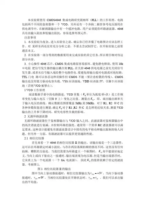
本实验要使用CMOS4046集成电路研究锁相环(PLL )的工作原理。
电路包括两个不同的鉴相器和一个VCO 。
另外还有一个齐纳二极管参考电压源用在供电调节中,在解调器输出中有一个缓冲电路。
用户必须提供环路滤波器。
4046具有高输入阻抗和低输出阻抗,容易选择外围元件。
注意事项1. 本实验较为复杂,进入实验室之前,确认你已经弄懂了电路预计应该怎样工作。
对 某样东西还没有充分分析之前,不要去尝试制作它。
在开始实验之前要通读本文。
2. 在实验第一部分得到的数据要用来完成实验的其它任务。
所以要仔细对待这部分内容。
3. 小心操作4046芯片,CMOS 集成电路很容易损坏。
避免静电释放,使用10k Ω电阻 把信号发生器的输出耦合到PLL 。
在关掉4046供电电源之前先关闭信号发生器,或者从信号输入端给整个电路供电。
要避免将输出端对电源或对地短路,TTL 门电 路可以容忍这种误操作但CMOS 不能(要注意松散的导线)。
CMOS 输出也没有能力驱动电容负载。
VSS 应该接地,VDD 应该接5V ,引脚5应该接地(否则VCO 被禁止)。
1 VCO 工作原理阅读数据手册中的电路描述。
VCO 常数(0K 单位为弧度/秒-伏)是工作频率变化与输入电压(引脚9上)变化之比值。
测量出0K ,即,画出输出频率关于输入电压的曲线。
确认数据范围要覆盖5kHz 到50kHz 。
对于R1, R2 和C 的各种参数取值进行测量,确定0K 对于R1 ,R2 和C 是怎样的近似关系。
测量VCO 输出的上升和下降时间,研究电容性负载的影响。
2 无源环路滤波器无源环路滤波器位于鉴相器输出与VCO 输入之间。
此滤波器对鉴相器输出中的高次谐波进行衰减,并控制环路的强度。
通常用一个简单RC 滤波器就可以满足要求,这种设计能避免有源滤波器设计中固有的电平移动和输出限制的恼人问题。
但另外一方面,有源滤波器可以提供更优越的性能。
2.1 相位比较器首先来看一下4046的相位比较器II 的输出。
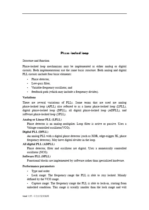
锁相环外文参考文献译文及原文目录外文参考文献译文1锁相环 (1)1.1锁相特性 (1)1.2历史与应用 (2)1.3其它应用 (4)2光通信元件 (5)2.1光纤 (5)2.2调制器和检测器 (6)外文参考文献原文1Phase Lock Loop (9)1.1Nature of Phaselock (9)1.2History and Application (10)1.3Other Applications (13)2Optical Communication Components (14)2.1The Optical Fiber (14)2.2Modulators and Detectors (17)1锁相环1.1锁相特性锁相环包含三个组成部分:1、相位检测器(PD)。
2、环路滤波器。
3、压控振荡器(VCO),其频率由外部电压控制。
相位检测器将一个周期输入信号的相位与压控振荡器的相位进行比较。
相位检测器的输出是它两个输入信号之间相位差的度量。
差值电压由环路滤波后,再加到压控振荡器上。
压控振荡器的控制电压使频率朝着减小输入信号与本振之间相位差的方向改变。
当锁相环处于锁定状态时,控制电压使压控振荡器的频率正好等于输入信号频率的平均值。
对于输入信号的每一周期,振荡器输出也变化一周,且仅仅变化一周。
锁相环的一个显而易见的应用是自动频率控制(AFC)。
用这种方法可以获得完美的频率控制,而传统的自动频率控制技术不可避免地存在某些频率误差。
为了保持锁定环路所需的控制电压,通常要求相位检测器有一个非零的输出,所以环路是在有一些相位误差条件下工作的。
不过实际上对于一个设计良好的环路这种误差很小。
一个稍微不同的解释可提供理解环路工作原理的更好说明。
让我们假定输入信号的相位或频率上携带了信息,并且此信号不可避免地受到加性噪声地干扰。
锁相接收机的作用是重建原信号而尽可能地去除噪声。
为了重建原始信号,接收机使用一个输出频率与预计信号频率非常接近的本机振荡器。
东海科学技术学院毕业设计(论文)文献综述题目:基于VHDL的全数字锁相环的设计系:机电工程系学生姓名:专业:班级:指导教师:起止日期:文献综述一、前言随着数字技术的不断发展和计算机的普及应用,全数字锁相环ADPLL ( All Digital Phase-Locked Loop)和电子设计自动化EDA(Electronic Design Automation)技术在通信、雷达、测量、医学、工业自动化、计算机应用、仪器仪表和自动化控制等领域得到了广泛的应用。
全数字锁相环(ADPLL),是指环路部件全部数字化,采用数字鉴相器、数字环路滤波器、数控振荡器构成锁相环路,并且系统中的信号全是数字信号。
具备可靠性高、工作稳定、调节方便等优点。
它的环路带宽和中心频率编程可调,易于构建高阶锁相环,并且应用在数字系统中时,不需A/ D 及D/ A 转换[ 1]。
电子设计自动化(EDA)是一种实现电子系统或电子产品自动化设计的技术,它与电子技术、微电子技术的发展密切相关,吸收了计算机科学领域的大多数最新研究成果,以高性能的计算机作为工作平台,是20世纪90年代初从CAD(计算机辅助设计)、CAM(计算机辅助制造)、CAT(计算机辅助测试)和CAE(计算机辅助工程)的概念发展而来的。
EDA技术就是以计算机为工具,在EDA软件平台上,根据硬件描述语言HDL完成的设计文件,自动地完成逻辑编译、化简、分割、综合及优化、布局线、仿真,直至对于特定目标芯片的适配编译、逻辑映射和编程下载等工作[ 11]。
设计者的工作仅限于利用软件的方式来完成对系统硬件功能的描述,在EDA工具的帮助下和应用相应的FPG刀CPLD器件,就可以得到最后的设计结果。
尽管目标系统是硬件,但整个设计和修改过程如同完成软件设计一样方便和高效。
当然,这里的所谓EDA主要是指数字系统的自动化设计,因为这一领域的软硬件方面的技术已比较成熟,应用的普及程度也已比较大。
附录2:外文原文,译文Modulating Direct Digital Synthesizer In the pursuit of more complex phase continuous modulation techniques, the control of the output waveform becomes increasingly more difficult with analog circuitry. In these designs, using a non-linear digital design eliminates the need for circuit board adjustments over yield and temperature. A digital design that meets these goals is a Direct Digital Synthesizer DDS. A DDS system simply takes a constant reference clock input and divides it down a to a specified output frequency digitally quantized or sampled at the reference clock frequency. This form of frequency control makes DDS systems ideal for systems that require precise frequency sweeps such as radar chirps or fast frequency hoppers. With control of the frequency output derived from the digital input word, DDS systems can be used as a PLL allowing precise frequency changes phase continuously. As will be shown, DDS systems can also be designed to control the phase of the output carrier using a digital phase word input. With digital control over the carrier phase, a high spectral density phase modulated carrier can easily be generated.This article is intended to give the reader a basic understanding of a DDS design, and an understanding of the spurious output response. This article will also present a sample design running at 45MHz in a high speed field programmable gate array from QuickLogic.A basic DDS system consists of a numerically controlled oscillator (NCO) used to generate the output carrier wave, and a digital to analog converter (DAC) used to take the digital sinusoidal word from the NCO and generate a sampled analog carrier. Since the DAC output is sampled at the reference clock frequency, a wave form smoothing low pass filter is typically used to eliminate alias components. Figure 1 is a basic block diagram of a typical DDS system generation of the output carrier from the reference sample clock input is performed by the NCO. The basic components of the NCO are a phase accumulator and a sinusoidal ROM lookup table. An optional phase modulator can also be include in the NCO design. This phase modulator will add phase offset to the output of the phase accumulator just before the ROM lookup table. This will enhance the DDS system design by adding the capabilities to phase modulate the carrier output of the NCO. Figure 2 is a detailed block diagram of a typical NCO design showing the optional phase modulator.FIGURE 1: Typical DDS System.FIGURE 2: Typical NCO Design.To better understand the functions of the NCO design, first consider the basic NCO design which includes only a phase accumulator and a sinusoidal ROM lookup table. The function of these two blocks of the NCO design are best understood when compared to the graphical representation of Euler’s formula ej wt = cos( wt) + jsin( wt). T hegraphical representation of Euler’s formula, as shown in Figure 3, is a unit vector rotating around the center axis of the real and imaginary plane at a velocity of wrad/s. Plotting the imaginary component versus time projects a sine wave while plotting the real component versus time projects a cosine wave. The phase accumulator of the NCO is analogous, or could be considered, the generator of the angular velocity component wrad/s. The phase accumulator is loaded, synchronous to the reference sample clock, with an N bit frequency word.This frequency word is continuously accumulated with the last sampled phase value by an N bit adder. The output of the adder is sampled at the reference sample clock by an N bit register. When the accumulator reaches the N bit maximum value, the accumulator rolls over and continues. Plotting the sampled accumulator values versus time produces a saw tooth wave form as shown below in Figure 3. FIGURE 3 Euler’s Equation Represented GraphicallyThe sampled output of the phase accumulator is then used to address a ROM lookup table of sinusoidal magnitude values. This conversion of the sampled phase to a sinusoidal magnitude is analogous to the projection of the real or imaginary component in time. Since the number of bits used by the phase accumulator determines the granularity of the frequency adjustment steps, a typical phase accumulator size is 24 to 32 bits. Since the size of the sinusoidal ROMtable is directly proportional to the addressing range, not all 24 or 32 bits of the phase accumulator are used to address the ROM sinusoidal table. Only the upper Y bits of the phase accumulator are used to address the sinusoidal ROM table, where Y < N bits and Y is typically but not necessarily equal to D, and D is the number of output magnitude bits from the sinusoidal ROM table.Since an NCO outputs a carrier based on a digital representation of the phase and magnitude of the sinusoidal wave form, designers have complete control over frequency, phase, and even amplitude of the output carrier. By adding a phase port and a phase adder to the basic NCO design, the output carrier of the NCO can be M array phase modulated where M equals the number of phase port bits and where M is less than or equal to the Y number of bits used to address the sinusoidal ROM table. For system designs that require amplitude modulation such as QAM, a magnitude port can be added to adjust the sinusoidal ROM table output. Note that this port is not shown in Figure 2 and that this feature is not demonstrated in the sample QuickLogic FPGA design. Finally, frequency modulation is a given with the basic NCO design. The frequency port can directly adjust the carrier output frequency. Since frequency words are loaded into the DDS synchronous to the sample clock, frequency changes are phase continuous.Although DDS systems give the designer complete control ofcomplex modulation synthesis, the representation of sinusoidal phase and magnitude in a non-linear digital format introduces new design complexities. In sampling any continuous-time signal, one must consider the sampling theory and quantization error.To understand the effects of the sampling theory on a DDS system, it is best to look at the DDS synthesis processes in both the time and frequency domain. As stated above, the NCO generates a sinusoidal wave form by accumulating the phase at a specified rate and then uses the phase value to address a ROM table of sinusoidal amplitude values. Thus, the NCO is essentially taking a sinusoidal wave form and sampling it with the rising or falling edge of the NCO input reference sampling clock. Figure 4 shows the time and frequency domain of the NCO processing. Note that this representation does not assume quantization.Based on the loaded frequency word, the NCO produces a set of amplitude output values at a set period. The frequency domain representation of this sinusoid is an impulse function at the specified frequency. The NCO, however, outputs discrete digital samples of this sinusoid at the NCO reference clock rate. In the time domain, the NCO output is a function of the sampling clock edge strobes multiplied by the sinusoid wave form producing a train of impulses at the sinusoid amplitude. In the frequency domain, the sampling strobes of the reference clock produce a train of impulses at frequencies of K times theNCO clock frequency where K = ... - 1, 0, 1, 2 .... Since the sampling clock was multiplied by the sinusoid in the time domain, the frequency domain components of the sinusoid and the sampling clock need to be convolved to produce the frequency domain representation of the NCO output.The frequency domain results are the impulse function at the fundamental frequency of the sinusoid and the alias impulse functions occurring at K times the NCO clock frequency plus or minus the fundamental frequency. The fundamental and alias component occur at: K*Fclk - FoutK*Fclk + FoutWhere K = ... -1, 0 , 1, 2 ..... and K = 0 is the NCO sinusoid fundamental frequencyFout is the specified NCO sinusoid output frequencyFclk is the NCO reference clock frequencyFIGURE 4 NCO Output Representation Time and Frequency Domain The DAC of the DDS system takes the NCO output values and translates these values into analog voltages. Figure 4 shows the time and frequency domain representations of the DAC processing starting with the NCO output. The DAC output is a sample and hold circuit that takes the NCO digital amplitude words and converts the value into an analog voltage and holds the value for one sample clock period. The timedomain plot of the DAC processing is the convolution of the NCO sampled output values with a pulse of one sample clock period. The frequency domain plot of the sampling pulse is a sin(x)/x function with the first null at the sample clock frequency. Since the time domain was convolved, the frequency domain is multiplied. This multiplication dampens the NCO output with the sin(x)/x envelope. This attenuation at the DAC output can be calculated as follows and a sample output spectrum is shown in Figure 5:Atten(F) = 20log[(sin(pF/Fclk)/pF/Fclk)] Where F is the output frequency Fclk is the sample clock frequencyFIGURE 5: DAC Output Representation in Time and Frequency Domain Aside from the sampling theory, the quantization of the real values into digital form must also be considered in the performance analysis of a DDS system. The spurious response of a DDS system is primarily dictated by two quantization parameters. These parameters are the phase quantization by the phase accumulator and the magnitude quantization by the ROM sinusoidal table and the DAC.As mentioned above, only the upper Y bits of the phase accumulator are used to address the ROM lookup table. It should be noted, however, that using only the upper Y bits of the phase accumulator introduces a phase truncation. When a frequency word containing a non-zero value in the lower (N-Y-1:0) bits is loaded into the DDS system, the lowernon-zero bits will accumulate to the upper Y bits and cause a phase truncation. The frequency at which the phase truncation occurs can be calculated by the following:Ftrunc = FW(N-Y- 1:0)/2N-Y* Fclk.A phase truncation will periodically (at the Ftrunc rate) phase modulate the output carrier forward 2p/28 to compensate for frequency word granularity greater than 2Y. The phase jump caused by the accumulation of phase truncated bits produces spurs around the fundamental.These spurs are located plus and minus the truncation frequency from the fundamental frequency and the magnitude of the spurs will be - 20log(2Y)dBc. A sample output of a phase truncation spur is shown in Figure 5.In a typical NCO design, the ROM sinusoidal table will hold a ¼ sine wave (0 , p/2) of magnitude values. The ROM table is generated by taking all possible phase value addresses and map to a real magnitude sine value rounded to the nearest D bits. Thus, the maximum error output is ±- ½ LSB giving a worst case spur of -20log(2D)dBc.Like the NCO ROM table, a DAC quantizes the digital magnitude values. A DAC, however, outputs an analog voltage corresponding to the digital input value. When designing the NCO sinusoidal ROM table, one should take some empirical data on the DAC linearity to betterunderstand the interaction between the ROM table and the DAC. The quantization for a DAC is specified against an ideal linear plot of digital input versus analog output. Two linearity parameters, differential and integral linearity, are used to specify a DAC’s p erformance.Differential linearity is the output step size from bit to bit. A DAC must guarantee a differential linearity of a maximum 1 LSB. When an input code is increased, the DAC output must increase. If the DAC voltage does not increase versus an increase digital input value, the DAC is said to be missing codes. Thus, a 10 bit DAC that has a differential linearity of greater that 1 LSB is only accurate to 9 or less bits. The number of accurate output bits will specify the DDS spurious performance as -20log(2dl) where dl is the number differential linear bits..Integral linearity is a measure of the DAC’s overall linear performance versus an ideal linear straight line. The straight line plot can be either a “best straight line” where DC offsets are pos sible at both the min and max outputs of the DAC, or the straight line can cross the end points of the min and max output values. A DAC will tend to have a characteristic curve that is traversed over the output range. Depending on the shape and symmetry (symmetry about the half way point of the DAC output) of this curve, output harmonics of the DDS fundamental output frequency will be produced. As these harmonics approach andcross the Nyquist frequency of Fclk/2, the harmonics become under sampled and reflect back into the band of interest, 0 to Fclk/2. This problem is best illustrated by setting the NCO output to Fclk/4 plus a slight offset. The third harmonic will fall minus 3 folds the small offset from the fundamental and the second harmonic will cross the Nyquist frequency by 2 folds the small offset leaving a reflected image back in the band of interest A sample plot of this frequency setup is shown in Figure 5.Other DAC characteristic that will produce harmonic distortion is any disruption of the symmetry of the output wave form such as a different rise and fall time. These characteristics can typically be corrected by board components external to the DAC such as an RF transformer, board layout issues, attenuation pads etc.Given the complexities of the DDS system, engineers should consider implementing the design using separate devices for the numerically controlled oscillator, the digital to analog converter, and the low pass filter. This approach allows for signal observation at many points in the system, yet is compact enough to be practical as an end-solution. Alternatively, the discrete implementation can serve as a prototyping vehicle for a single-chip mixed signal ASIC.The author developed a version of the design using a Harris HI5721 evaluation board for the DAC. The NCO at the heart of the DDS design,and a random generator to test signal modulation, was implemented into about 65% of a QuickLogic field programmable gate array (FPGA). This FPGA, a QL16x24B 4000-gate device, was chosen for its high performance, ease-of-use, and powerful development tools.The NCO design included following:Developed in Verilog with the 8 bit CLA adder schematiccaptured and net listed to Verilog32 bit frequency word input32 phase accumulator pipelined over 8 bits8 bit phase moudulation word input8 bit sine ROM look-up tableThe design was described mostly in Verilog, with an 8 bit carry look ahead adder modified from QuickLogic’s macro library netlisted to Verilog. The whole design cycle was less than four days (two days to describe the design and a day and a half to prototype the hardware). Everything worked perfectly the first time, with the design running at an impressive 45MHz as predicted by the software simulation tools.Plots used in the article to illustrate DDS performance parameters were provided from the test configuration.Figure 6 below shows the external IO interface to the NCO design .The function of each signal is described in the following table.Signal Function TableFigure 6: The External IO InterfaceTop LevelThe top level of the NCO design instantiates the functional blocks of the NCO design and the PN generator block.PN GeneratorThis module is not part of the NCO design but is used to produce a sample random data pattern to modulate the carrier output. This module uses the PNCLK input to clock two Gold code 5 bit PN generators. The outputs of the PN generators are IDATA and QDATA outputs.The lower level block of this NCO design consist of a synchronous frequency word input register, a synchronous phase word input register, a 32 bit pipe lined phase accumulator, an 8 bit phase adder, and a sin lockup table. A detailed description of each of the NCO blocks and thePN generator are provided in the following sections.Load Frequency WordThe load frequency word block is a synchronizing loading circuit. The FREQWORD[31:0] input drives a the data input to the 32 bit fwreg register that is sampled on the rising edge of the FWWRN write strobe. The FWWRN strobe also drives the data input to a metastable flip flop fwwrnm that is used in conjunction with a synchronous register fwwrns to produce a FWWRN rising edge strobe. This rising edge strobe loadp1 is then piped for an additional 3 clock cycles producing the load strobes loadp2, loadp3, and loadp4. The load strobes are used to signal when to update the synchronous pipe line 8 bit registers pipefw1, pipefw2, pipefw3, and pipefw4 to the sampled frequency word content. The pipe line registers are concatenated to produce the 32 bit synchronous frequency word output SYNCFREQ[31:0] that is staggered to compensate for the 32 bit pipe lined phase adder.Phase Word AccumulatorThe phase accumulator block is a 32 bit accumulator that is pipe lined in 8 bit sections. This module instanciates a schematic captured carry lock ahead CLA adder that has a carry in and carry out port. The synchronous frequency word, staggered to match the pipe lined accumulator, is loaded into the B input of the CLA adders. The sum output of the CLA adders are registered in the pipe registered with theoutput tied back to the A input of the CLA adders. The carry output of the CLA adders is registered in the pipec registers with the output tied to the next most significant CLA adder carry input. The most significant sum output register pipe4 is assigned to the PHASE output port giving a phase value quantized to 8 bits. A digital sine and cosine value is also calculated from the pipe4 register and brought out of the chip as SIN and COS.Load Phase WordThe load phase word block is a synchronizing loading circuit. The PHASEWORD[7:0] input drives the data input to the 32 bit pwreg register that is sampled on the rising edge of the PWWRN write strobe. The PWWRN strobe also drives the data input to a metastable flip flop pwwrnm that is used in conjunction with a synchronous register pwwrns to produce a FWWRN rising edge strobe. This rising edge strobe load is used to signal when to update the synchronous phase word register phswd. The phswd register is assigned to the synchronous phase word output SYNCPHSWD[7:0].Phase ModulatorThe phase modulator block is used to phase offset the phase accumulator 8 bit quantized output with the synchronous phase word from the load phase word block. This module instantiates a CLA adder with the A input tied to the synchronous phase output and the B inputtied to the phase accumulator output. The sum output of the adder is registered in the mphsreg register and assigned to the MODPHASE output port. A modulated version of the sine and cosine values are calculated and brought out of the chip as MSIN and MCOS.Sine LockupThis module takes the modulated phase value form the phase modulator block and translated the quantized 8 bit value into a sine wave form amplitude value quantized to 8 bits. The translation from phase to amplitude is performed by a sine ROM table that in instantiated in this module. The ROM table is reduced to a ¼ of the symmetrical sine wave form and the MSB of the sine wave form is equivalent to the modulated phase module performs the calculations to reconstruct a complete period of the sine wave form f rom the ¼ representation of the ROM table and the MSB of the modulated phase input. To better understand the processing of this module, consider the following. The modulated phase value is a 0 to 2p value quantized to 8 bits 2p/28. The quantized value for p/2, p, 3p/2, and 2p are 0x3F, 0x7F, 0xBF, and 0xFF. The amplitude values for 0 to p/2 is stored in the ROM table. The amplitude values for p/2 to p are the ROM table output in the reverse order. The amplitude values for p to 3p/2 are the same output as the amplitude value from 0 to p/2 with the output from the ROM table inverted. Finally the amplitude value for 3p/2 to 2p are the same as for pto 3p/2 with the ROM table accessed in reverse.This module manages the address values to the ROM table and the amplitude outputs to form the complete period of the sine wave form. The first process of generating the sine wave function is the addressing of the ROM table such that phase angles p/2 to p and 3p/2 to 2p are addressed in the reverse order. Reverse addressing is accomplished by simply inverting the ROM table address input vector. The phase modulated address input is inverted when the MODPHASE[6] is one and is then registered in the phaseadd register. The phase address is used to address the ROM sine table with the output registered in the qwavesin_ff register. To construct the negative amplitude values of the sine wave form, the MSB of the modulate phase word input is registered twice in modphase_msb1_ff and modphase_msb2_ff, compensating for the two cycle latency of the phaseadd and qwavesin_ff registers. The delayed MSB bit is used to invert the ROM table output when one. The altered ROM table output and the invert of the delayed modulated phase word MSB are finally registered in by the dac_ff register and then assigned to the DACOUT output port.Sine ROM TableThis module is the sine wave form ROM table. This table converts the phase word input to a sine amplitude output. To conserve area, only ¼ of the symmetrical sine wave form is stored in the ROM. The sine valuesstored in this table are the 0 to p/2 unsigned values quantized to 8 bits. Thus, the ROM table requires a 6 bit phase address input and outputs a 7 bit amplitude output. The sinlup module processes the phase and amplitude values to produce a complete sine period.Dan Morelli has over 9 years of design and management experience. His areas of expertise include spread spectrum communications (involving GPS, TDRSS, and , PC chip set and system architecture, cell library development (for ECL devices) and ASIC development. He has been published and has multiple patents awarded and pending. Dan currently works for Accelent Systems Inc., an electronic design consulting company, where he is a founder and the VP of Engineering.数字频率合成器在探讨许多复杂的相位持续的调制技术中,对模拟电路中输出波形的操纵已经愈来愈困难。
中英文对照外文翻译(文档含英文原文和中文翻译)数字信号处理一、导论数字信号处理(DSP)是由一系列的数字或符号来表示这些信号的处理的过程的。
数字信号处理与模拟信号处理属于信号处理领域。
DSP包括子域的音频和语音信号处理,雷达和声纳信号处理,传感器阵列处理,谱估计,统计信号处理,数字图像处理,通信信号处理,生物医学信号处理,地震数据处理等。
由于DSP的目标通常是对连续的真实世界的模拟信号进行测量或滤波,第一步通常是通过使用一个模拟到数字的转换器将信号从模拟信号转化到数字信号。
通常,所需的输出信号却是一个模拟输出信号,因此这就需要一个数字到模拟的转换器。
即使这个过程比模拟处理更复杂的和而且具有离散值,由于数字信号处理的错误检测和校正不易受噪声影响,它的稳定性使得它优于许多模拟信号处理的应用(虽然不是全部)。
DSP算法一直是运行在标准的计算机,被称为数字信号处理器(DSP)的专用处理器或在专用硬件如特殊应用集成电路(ASIC)。
目前有用于数字信号处理的附加技术包括更强大的通用微处理器,现场可编程门阵列(FPGA),数字信号控制器(大多为工业应用,如电机控制)和流处理器和其他相关技术。
在数字信号处理过程中,工程师通常研究数字信号的以下领域:时间域(一维信号),空间域(多维信号),频率域,域和小波域的自相关。
他们选择在哪个领域过程中的一个信号,做一个明智的猜测(或通过尝试不同的可能性)作为该域的最佳代表的信号的本质特征。
从测量装置对样品序列产生一个时间或空间域表示,而离散傅立叶变换产生的频谱的频率域信息。
自相关的定义是互相关的信号本身在不同时间间隔的时间或空间的相关情况。
二、信号采样随着计算机的应用越来越多地使用,数字信号处理的需要也增加了。
为了在计算机上使用一个模拟信号的计算机,它上面必须使用模拟到数字的转换器(ADC)使其数字化。
采样通常分两阶段进行,离散化和量化。
在离散化阶段,信号的空间被划分成等价类和量化是通过一组有限的具有代表性的信号值来代替信号近似值。
Phase-locked loopStructure and functionPhase-locked loop mechanisms may be implemented as either analog or digital circuits. Both implementations use the same basic structure. Both analog and digital PLL circuits include four basic elements:▪Phase detector,▪Low-pass filter,▪Variable-frequency oscillator, and▪feedback path (which may include a frequency divider).VariationsThere are several variations of PLLs. Some terms that are used are analog phase-locked loop (APLL) also referred to as a linear phase-locked loop (LPLL), digital phase-locked loop (DPLL), all digital phase-locked loop (ADPLL), and software phase-locked loop (SPLL).Analog or Linear PLL (LPLL)Phase detector is an analog multiplier. Loop filter is active or passive. Uses a V oltage-controlled oscillator(VCO).Digital PLL (DPLL)An analog PLL with a digital phase detector (such as XOR, edge-trigger JK, phase frequency detector). May have digital divider in the loop.All digital PLL (ADPLL)Phase detector, filter and oscillator are digital. Uses a numerically controlled oscillator (NCO).Software PLL (SPLL)Functional blocks are implemented by software rather than specialized hardware. Performance parameters▪Type and order▪Lock range: The frequency range the PLL is able to stay locked. Mainly defined by the VCO range.▪Capture range: The frequency range the PLL is able to lock-in, starting from unlocked condition. This range is usually smaller than the lock range and willdepend e.g. on phase detector.▪Loop bandwidth: Defining the speed of the control loop.▪Transient response: Like overshoot and settling time to a certain accuracy (like 50ppm).▪Steady-state errors: Like remaining phase or timing error▪Output spectrum purity: Like sidebands generated from a certain VCO tuning voltage ripple.▪Phase-noise: Defined by noise energy in a certain frequency band (like 10kHz offset from carrier). Highly dependent on VCO phase-noise, PLL bandwidth, etc.▪General parameters: Such as power consumption, supply voltage range, output amplitude, etc.ApplicationsPhase-locked loops are widely used for synchronization purposes; in space communications for coherent demodulation and threshold.extension, bit synchronization, and symbol synchronization. Phase-locked loops can also be used to demodulate frequency-modulated signals. In radio transmitters, a PLL is used to synthesize new frequencies which are a multiple of a reference frequency, with the same stability as the reference frequency.Other applications include:▪Demodulation of both FM and AM signals▪Recovery of small signals that otherwise would be lost in noise (lock-in amplifier)▪Recovery of clock timing information from a data stream such as from a disk drive▪Clock multipliers in microprocessors that allow internal processor elements to run faster than external connections, while maintaining precise timing relationships▪DTMF decoders, modems, and other tone decoders, for remote control and telecommunicationsClock recoverySome data streams, especially high-speed serial data streams (such as the raw stream of data from the magnetic head of a disk drive), are sent without an accompanying clock. The receiver generates a clock from an approximate frequency reference, and then phase-aligns to the transitions in the data stream with a PLL. This process is referred to as clock recovery. In order for this scheme to work, the data stream must have a transition frequently enough to correct any drift in the PLL's oscillator. Typically, some sort of redundant encoding is used, such as8b/10b encoding. DeskewingIf a clock is sent in parallel with data, that clock can be used to sample the data. Because the clock must be received and amplified before it can drive the flip-flopswhich sample the data, there will be a finite, and process-, temperature-, and voltage-dependent delay between the detected clock edge and the received data window. This delay limits the frequency at which data can be sent. One way of eliminating this delay is to include a deskew PLL on the receive side, so that the clock at each data flip-flop is phase-matched to the received clock. In that type of application, a special form of a PLL called a delay-locked loop (DLL) is frequently used.Clock generationMany electronic systems include processors of various sorts that operate at hundreds of megahertz. Typically, the clocks supplied to these processors come from clock generator PLLs, which multiply a lower-frequency reference clock (usually 50 or 100 MHz) up to the operating frequency of the processor. The multiplication factor can be quite large in cases where the operating frequency is multiple gigahertz and the reference crystal is just tens or hundreds of megahertz.Spread spectrumAll electronic systems emit some unwanted radio frequency energy. Various regulatory agencies (such as the FCC in the United States) put limits on the emitted energy and any interference caused by it. The emitted noise generally appears at sharp spectral peaks (usually at the operating frequency of the device, and a few harmonics).A system designer can use a spread-spectrum PLL to reduce interference with high-Q receivers by spreading the energy over a larger portion of the spectrum. For example, by changing the operating frequency up and down by a small amount (about 1%), a device running at hundreds of megahertz can spread its interference evenly over a few megahertz of spectrum, which drastically reduces the amount of noise seen on broadcast FM radio channels, which have a bandwidth of several tens of kilohertz. Clock distributionTypically, the reference clock enters the chip and drives a phase locked loop (PLL), which then drives the system's clock distribution. The clock distribution is usually balanced so that the clock arrives at every endpoint simultaneously. One of those endpoints is the PLL's feedback input. The function of the PLL is to compare the distributed clock to the incoming reference clock, and vary the phase and frequency ofits output until the reference and feedback clocks are phase and frequency matched. PLLs are ubiquitous—they tune clocks in systems several feet across, as well as clocks in small portions of individual chips. Sometimes the reference clock may not actually be a pure clock at all, but rather a data stream with enough transitions that the PLL is able to recover a regular clock from that stream. Sometimes the reference clock is the same frequency as the clock driven through the clock distribution, other times the distributed clock may be some rational multiple of the reference.Jitter and noise reductionOne desirable property of all PLLs is that the reference and feedback clock edges be brought into very close alignment. The average difference in time between the phases of the two signals when the PLL has achieved lock is called the static phase offset (also called the steady-state phase error). The variance between these phases is called tracking jitter. Ideally, the static phase offset should be zero, and the tracking jitter should be as low as possible.Phase noise is another type of jitter observed in PLLs, and is caused by the oscillator itself and by elements used in the oscillator's frequency control circuit. Some technologies are known to perform better than others in this regard. The best digital PLLs are constructed with emitter-coupled logic (ECL) elements, at the expense of high power consumption. To keep phase noise low in PLL circuits, it is best to avoid saturating logic families such as transistor-transistor logic (TTL) or CMOS.[citation needed]Another desirable property of all PLLs is that the phase and frequency of the generated clock be unaffected by rapid changes in the voltages of the power and ground supply lines, as well as the voltage of the substrate on which the PLL circuits are fabricated. This is called substrate and supply noise rejection. The higher the noise rejection, the better.To further improve the phase noise of the output, an injection locked oscillator can be employed following the VCO in the PLL.Frequency SynthesisIn digital wireless communication systems (GSM, CDMA etc.), PLLs are used to provide the local oscillator for up-conversion during transmission and down-conversion during reception. In most cellular handsets this function has been largely integrated into a single integrated circuit to reduce the cost and size of the handset. However, due to the high performance required of base station terminals, the transmission and reception circuits are built with discrete components to achieve the levels of performance required. GSM local oscillator modules are typically built with a frequency synthesizer integrated circuit and discrete resonator VCOs.Frequency synthesizer manufacturers include Analog Devices, National Semiconductor and Texas Instruments. VCO manufacturers include Sirenza, Z-Communications, Inc.Phase-locked loop block diagramDigital phase-locked loop block diagramA phase detector compares two input signals and produces an error signal which is proportional to their phase difference. The error signal is then low-pass filtered and used to drive a VCO which creates an output phase. The output is fed through an optional divider back to the input of the system, producing a negative feedback loop. If the output phase drifts, the error signal will increase, driving the VCO phase in the opposite direction so as to reduce the error. Thus the output phase is locked to the phase at the other input. This input is called the reference.Analog phase locked loops are generally built with an analog phase detector, low pass filter and VCO placed in a negative feedback configuration. A digital phase locked loop uses a digital phase detector; it may also have a divider in the feedback path or in the reference path, or both, in order to make the PLL's output signal frequency a rational multiple of the reference frequency. A non-integer multiple of the reference frequency can also be created by replacing the simple divide-by-N counter in the feedback path with a programmable pulse swallowing counter. This technique is usually referred to as a fractional-N synthesizer or fractional-N PLL.The oscillator generates a periodic output signal. Assume that initially the oscillator is at nearly the same frequency as the reference signal. If the phase from the oscillator falls behind that of the reference, the phase detector changes the control voltage of the oscillator so that it speeds up. Likewise, if the phase creeps ahead of the reference, the phase detector changes the control voltage to slow down the oscillator. Since initially the oscillator may be far from the reference frequency, practical phase detectors may also respond to frequency differences, so as to increase the lock-in range of allowable inputs.Depending on the application, either the output of the controlled oscillator, or the control signal to the oscillator, provides the useful output of the PLL system.Phase detectorThe two inputs of the phase detector are the reference input and the feedback from the VCO. The PD output controls the VCO such that the phase difference between the two inputs is held constant, making it a negative feedback system. There are severaltypes of phase detectors in the two main categories of analog and digital.Different types of phase detectors have different performance characteristics.For instance, the frequency mixer produces harmonics that adds complexity in applications where spectral purity of the VCO signal is important. The resulting unwanted sidebands, also called "reference spurs" can dominate the filter requirements and reduce the capture range and lock time well below the requirements. In these applications the more complex digital phase detectors are used which do not have as severe a reference spur component on their output. Also, when in lock, the steady-state phase difference at the inputs using this type of phase detector is near 90 degrees. The actual difference is determined by the DC loop gain.A bang-bang charge pump phase detector must always have a dead band where the phases of inputs are close enough that the detector detects no phase error. For this reason, bang-bang phase detectors are associated with significant minimum peak-to-peak jitter, because of drift within the dead band.However these types, having outputs consisting of very narrow pulses at lock, are very useful for applications requiring very low VCO spurious outputs. The narrow pulses contain very little energy and are easy to filter out of the VCO control voltage. This results in low VCO control line ripple and therefore low FM sidebands on the VCO.In PLL applications it is frequently required to know when the loop is out of lock. The more complex digital phase-frequency detectors usually have an output that allows a reliable indication of an out of lock condition.ModelingTime domain modelThe equations governing a phase-locked loop with an analog multiplier as the phase detector and linear filter may be derived as follows. Let the input to the phase detector be xr(θr(t))and the output of the VCO is xc(θc(t))with phases θr(t)and θc(t).Functions xc(θ) and xr(θ) describe waveforms of signals. Then the output of the phasedetector xm(t) is given byxm(t) = xr(θr(t))xc(θc(t))the VCO frequency is usually taken as a function of the VCO input g(t) aswhere gv is the sensitivity of the VCO and is expressed in Hz / V; ωc is a free-running frequency of VCO.The Loop Filter can be described by system of linear differential equationswhere xm(t) is an input of the filter, xf(t) is an output of the filter, A is n-by-n matrix,. represents an initial state of the filter. The star symbol is a conjugate transpose.Hence the following system describes PLLwhere φ0 is an initial phase shift.Phase domain modelConsider the input of pll xr(θr(t))and VCO output xc(θc(t))are high frequency signals. Then for any piecewise differentiable 2π-periodic functions xr(θ) and xc(θ) there is a function φ(θ) such that the output G(t) of Filterin phase domain is asymptotically equal ( the difference G(t) −xf(t)is small with respect to the frequencies) to the output of the Filter in time domain model.Here function φ(θ) is a phase detector characteristic.Denote by θe(t) the phase differenceθe = θr(t) −θc(t).Then the following dynamical system describes PLL behaviorHere ωe = ωr−ωc; ωr is a frequency of reference oscillator( we assume that ωr is constant).ExampleConsider sinusoidal signalsand simple one-pole RC circuit as a filter. Time domain model takes formPD characteristics for this signals is equal[14] toHence the phase domain model takes formThis system of equations is equivalent to the equation of mathematical pendulumLinearized phase domain modelPhase locked loops can also be analyzed as control systems by applying the Laplace transform. The loop response can be written as:Where▪θo is the output phase in radians▪θi is the input phase in radians▪Kp is the phase detector gain in volts per radian▪Kv is the VCO gain in radians per volt-second▪F(s) is the loop filter transfer function (dimensionless)The loop characteristics can be controlled by inserting different types of loop filters. The simplest filter is a one-pole RC circuit. The loop transfer function in this case is:The loop response becomes:This is the form of a classic harmonic oscillator. The denominator can be related to that of a second order system:Where▪ζ is the damping factor▪ωn is the natural frequency of the loopFor the one-pole RC filter,The loop natural frequency is a measure of the response time of the loop, and the damping factor is a measure of the overshoot and ringing. Ideally, the natural frequency should be high and the damping factor should be near 0.707 (critical damping). With a single pole filter, it is not possible to control the loop frequency and damping factor independently. For the case of critical damping,A slightly more effective filter, the lag-lead filter includes one pole and one zero. This can be realized with two resistors and one capacitor. The transfer function for this filter isThis filter has two time constantsτ1 = C(R1 + R2)τ2 = CR2Substituting above yields the following natural frequency and damping factorThe loop filter components can be calculated independently for a given natural frequency and damping factorReal world loop filter design can be much more complex e.g. using higher order filters to reduce various types or source of phase noise.锁相环结构和功能锁相环机制,可以实现模拟或数字电路。
外文资料Phase-locked loop Technology :A phase-locked loop or phase lock loop (PLL) is a control system that generates a signal that has a fixed relation to the phase of a "reference" signal. A phase-locked loop circuit responds to both the frequency and the phase of the input signals, automatically raising or lowering the frequency of a controlled oscillator until it is matched to the reference in both frequency and phase. A phase-locked loop is an example of a control system using negative feedback. In the order of the PLL is the way of made the frequency stability in the send up wireless,include VCO and PLL integrated circuits,VCO send up a signal,some of the signal is output,and the other through the frequency division with PLL integrated circuits generate the local signal making compared.In the order to remain the same,it’s must be remain the phase displacement same.If the phase displacement have some changes,the output of the PLL integrated circuits have some changes too,to controlle VCO until phase diffe rence to restore,make both cotrolled oscillator’s frequency and phase with input signal which is close-loop electronic circuit keep firm relationship.Phase-locked loops are widely used in radio, telecommunications, computers and other electronic applications. They may generate stable frequencies, recover a signal from a noisy communication channel, or distribute clock timing pulses in digital logic designs such as microprocessors. Since a single integrated circuit can provide a complete phase-locked-loop building block, the technique is widely used in modern electronic devices, with output frequencies from a fraction of a cycle per second up to many gigahertz.Earliest research towards what became known as the phase-locked loop goes back to 1932, when British researchers developed an alternative to Edwin Armstrong's superheterodyne receiver, the Homodyne. In the homodyne or synchrodyne system, a local oscillator was tuned to the desired input frequency and multiplied with the input signal. The resulting output signal included the original audio modulation information.The intent was to develop an alternative receiver circuit that required fewer tuned circuits than the superheterodyne receiver. Since the local oscillator would rapidly drift in frequency, an automatic correction signal was applied to the oscillator, maintaining it in the same phase and frequency as the desired signal. The technique was described in 1932, in a paper by H.de Bellescise, in the French journal Onde Electrique.In analog television receivers since at least the late 1930s, phase-locked-loop horizontal and vertical sweep circuits are locked to synchronization pulses in the broadcast signal. When Signetics introduced a line of monolithic integrated circuits that were complete phase-locked loop systems on a chip in 1969, applications for the technique multiplied. A few years later RCA introduced the "CD4046" CMOS Micropower Phase-Locked Loop, which became a popular integrated circuit. Applications:Phase-locked loops are widely used for synchronization purposes; in space communications for coherent carrier tracking and threshold extension, bit synchronization, and symbol synchronization. Phase-locked loops can also be used to demodulate frequency-modulated signals. In radio transmitters, a PLL is used to synthesize new frequencies which are a multiple of a reference frequency, with the same stability as the reference frequency.Clock recovery :Some data streams, especially high-speed serial data streams (such as the raw stream of data from the magnetic head of a disk drive), are sent without an accompanying clock. The receiver generates a clock from an approximate frequency reference, and then phase-aligns to the transitions in the data stream with a PLL. This process is referred to as clock recovery. In order for this scheme to work, the data stream must have a transition frequently enough to correct any drift in the PLL's oscillator. Typically, some sort of redundant encoding is used; 8B10B is very common.Deskewing :If a clock is sent in parallel with data, that clock can be used to sample the data.Because the clock must be received and amplified before it can drive the flip-flops which sample the data, there will be a finite, and process-, temperature-, and voltage-dependent delay between the detected clock edge and the received data window. This delay limits the frequency at which data can be sent. One way of eliminating this delay is to include a deskew PLL on the receive side, so that the clock at each data flip-flop is phase-matched to the received clock. In that type of application, a special form of a PLL called a Delay-Locked Loop (DLL) is frequently used.Clock generation:Many electronic systems include processors of various sorts that operate at hundreds of megahertz. Typically, the clocks supplied to these processors come from clock generator PLLs, which multiply a lower-frequency reference clock (usually 50 or 100 MHz) up to the operating frequency of the processor. The multiplication factor can be quite large in cases where the operating frequency is multiple gigahertz and the reference crystal is just tens or hundreds of megahertz.Spread spectrum:All electronic systems emit some unwanted radio frequency energy. Various regulatory agencies (such as the FCC in the United States) put limits on the emitted energy and any interference caused by it. The emitted noise generally appears at sharp spectral peaks (usually at the operating frequency of the device, and a few harmonics).A system designer can use a spread-spectrum PLL to reduce interference with high-Q receivers by spreading the energy over a larger portion of the spectrum. For example, by changing the operating frequency up and down by a small amount (about 1%), a device running at hundreds of megahertz can spread its interference evenly over a few megahertz of spectrum, which drastically reduces the amount of noise seen by FM receivers which have a bandwidth of tens of kilohertz.中文翻译锁相环技术:锁相环或锁相回路(PLL)是一个信号控制系统,即用来锁定一系列的“参考”信号。
摘要频率合成器是以一个或少量的高准确度和高稳定度的标准频率作为参考频率,由此导出多个或大量的输出频率,这些输出的准确度与稳定度与参考频率是一致的。
在通信、雷达、测控、仪器表等电子系统中有广泛的应用。
频率合成器有直接式频率合成器、直接数字式频率合成器及锁相频率合成器三种基本模式,前两种属于开环系统,因此是有频率转换时间短,分辨率较高等优点,而锁相频率合成器是一种闭环系统,其频率转换时间和分辨率均不如前两种好,但其结构简单,成本低。
并且输出频率的准确度不逊色与前两种,因此锁相环频率合成已获得广泛的应用。
而VCO作为其中一个必不可少的重要部件,其质量可以左右整个环路的性能。
负阻集成LCVCO由于具有工作频率高、波形好、频稳度高、相位噪声低、性能可靠等优点,适于作为甚高频和特高频VCO。
关键词:MC1648;锁相环;频率合成器AbstractThe frequency synthesizer with high accuracy and high stability of the standard frequency of one or a few as the reference frequency, which leads to multiple or large amount of output frequency, accuracy and stability of the output and the reference frequency is consistent. There are widely applied in communication, radar, measurement and control, instruments and other electronic systems. Frequency synthesizer has the direct frequency synthesizer, DDS and PLL frequency synthesizer in three basic models, the former two belongs to the open loop system, so there is short frequency conversion time, resolution is higher, and the PLL frequency synthesizer is a closed loop system, the frequency conversion time and resolution is not as good as the first two good, but it has the advantages of simple structure, low cost. And the output frequency accuracy inferior to the former two, thus PLL frequency synthesis has been widely applied. VCO is one of the essential components, the performance of quality around the whole loop. Negative resistance integrated LCVCO because of the high operating frequency, a good waveform, frequency stability, low phase noise, high performance and reliable, suitable for VHF and UHF VCO. Therefore the PLL frequency synthesis based on MC1648.Key words:MC1648;PLL Frequency ;Synthesizer毕业论文(设计)原创性声明本人所呈交的毕业论文(设计)是我在导师的指导下进行的研究工作及取得的研究成果。
本科毕业设计(论文)外文翻译译文学生姓名:王惠院(系):电子工程学院仪器系专业班级:测控0701指导教师:刘选朝完成日期: 20 11 年 3 月 7 日咨询应用工程师- 33关于直接数字频率合成器的问题作者Eva Murphy [eva.murphy@]Colm Slattery [colm.slattery@]什么是直接数字频率合成器?直接数字频率合成器(DDS)是一种产生模拟波形(通常是正弦波)的仪器,这种仪器是生成一个数字形式的时变信号,然后执行数字到模拟的转换。
因为用一个DDS设备操作主要是数字形式,所以它可以提供输出频率之间的快速转换,较高的频率分辨率并且可以在一个宽频带上进行操作。
随着设计和工艺技术的进步,现在的DDS器件都非常小巧,在低功率下也可以工作。
为什么我们要使用直接数字频率合成器(DDS)?难道就没有其他产生频率的简单方法吗?能够准确地产生和控制各种频率和轮廓的波形的能力已成为一个通用于多个行业重要要求。
在通信系统中能否利用良好的杂散性提供低相位噪声可变频率的活跃来源,或仅产生用于工业或生物医学测试设备的应用的频率刺激,便利、简洁和低成本是重要的设计考虑因素。
频率产生的多种可能性对设计师来说是开放的,从锁相回路(PLL)——极高频率合成的基础技术,到以数模转换器(DAC)的动态编制程序输出来产生低频任意波形。
但是DDS技术迅速在解决频率(或波形)产生的通信和工业应用要求上得到接受,因为单芯片集成电路器件可以简单的产生可编程模拟输出波形,具有较高的分辨率和精度。
此外,在这两种工艺技术和设计的不断改进也使得成本和功耗较从前降低了许多。
例如,AD9833——基于DDS的可编程波形发生器(图1)在5.5 V的电压下工作工作具有25 MHz的时钟,消耗的最大功率为30毫瓦。
图1 单片波形发生器使用直接数字频率合成器(DDS)的主要优点有哪些?像AD9833 之类的DDS器件都可通过一个高速串行外设接口(SPI)进行编程,并且只需要一个外部时钟来生成简单的正弦波。
数字示波器外文翻译文献(文档含中英文对照即英文原文和中文翻译)原文:Design and FPGA implementation of a wireless hyperchaotic communication system for secure real-time image transmission AbstractIn this paper, we propose and demonstrate experimentally a new wireless digital encryption hyperchaotic communication system based on radio frequency (RF) communication protocols for secure real-time data or image transmission. A reconfigurable hardware architecture is developed to ensure the interconnection between two field programmable gate array developmentplatforms through XBee RF modules. To ensure the synchronization and encryption of data between the transmitter and the receiver, a feedback masking hyperchaotic synchronization technique based on a dynamic feedback modulation has been implemented to digitally synchronize the encrypter hyperchaotic systems. The obtained experimental results show the relevance of the idea of combining XBee (Zigbee or Wireless Fidelity) protocol, known for its high noise immunity, to secure hyperchaotic communications. In fact, we have recovered the information data or image correctly after real-time encrypted data or image transmission tests at a maximum distance (indoor range) of more than 30 m and with maximum digital modulation rate of 625,000 baud allowing a wireless encrypted video transmission rate of 25 images per second with a spatial resolution of 128 ×128 pixels. The obtained performance of the communication system is suitable for secure data or image transmissions in wireless sensor networks.IntroductionOver the past decades, the confidentiality of multimedia communications such as audio, images, and video has become increasingly important since communications of digital products over the network (wired/wireless) occur more frequently. Therefore, the need for secure data and transmission is increasing dramatically and defined by the required levels of security depending on the purpose of communication. To meet these requirements, a wide variety of cryptographic algorithms have been proposed. In this context, the main challenge of stream cipher cryptography relates to the generation of long unpredictable key sequences. More precisely, the sequence has to be random, its period must be large, and the various patterns of a given length must be uniformly distributed over the sequence. Traditional ciphers like DES, 3DES, IDEA, RSA, or AES are less efficient for real-time secure multimedia data encryption systems and exhibit some drawbacks and weakness in the high streamdata encryption. Indeed, the increase and availability of a high-power computation machine allow a force brute attack against these ciphers. Moreover, for some applications which require a high-levelcomputation and where a large computational time and high computing power are needed (for example, encryption of large digital images), these cryptosystems suffer from low-level efficiency. Consequently, these encryption schemes are not suitable for many high-speed applications due to their slow speed in real-time processing and some other issues such as in the handling of various data formatting. Over the recent years, considerable researches have been taken to develop new chaotic or hyperchaotic systems and for their promising applications in real-time encryption and communication. In fact, it has been shown that chaotic systems are good candidates for designing cryptosystems with desired properties. The most prominent is sensitivity dependence on initial conditions and system parameters, and unpredictable trajectories.Furthermore, chaos-based and other dynamical systembased algorithms have many important properties such as the pseudorandom properties, ergodicity and nonperiodicity. These properties meet some requirements such as sensitivity to keys, diffusion, and mixing in the cryptographic context. Therefore, chaotic dynamics is expected to provide a fast and easy way for building superior performance cryptosystems, and the properties of chaotic maps such as sensitivity to initial conditions and random-like behavior have attracted the attention to develop data encryption algorithms suitable for secure multimedia communications. Until recently, chaotic communication has been a subject of major interest in the field of wireless communications. Many techniques based on chaos have been proposed such as additive chaos masking (ACM), where the analog message signal is added to the output of the chaos generator within the transmitter. In, chaos shift keying is used where the binary message signal selects the carrier signal from two or more different chaotic attractors. Authors use chaotic modulation where the message information modulates a parameter of the chaotic generator. Chaos control methods rely on the fact that small perturbations cause the symbolic dynamics of a chaotic system to track a prescribed symbol sequence. In, the receiver system is designed in an inverse manner to ensure the recovery of theencryption signal. An impulsive synchronization scheme is employed to synchronize chaotic transmitters and receivers. However, all of these techniques do not provide a real and practical solution to the challenging issue of chaotic communication which is based on extreme sensitivity of chaotic synchronization to both the additive channel noise and parameter mismatches. Precisely, since chaos is sensitive to small variations of its initial conditions and parameters, it is very difficult to synchronize two chaotic systems in a communication scheme. Some proposed synchronization techniques have improved the robustness to parameter mismatches as reported in, where impulsive chaotic synchronization and an open-loop-closed-loopbased coupling scheme are proposed, respectively. Other authors proposed to improve the robustness of chaotic synchronization to channel noise, where a coupled lattice instead of coupled single maps is used to decrease the master-slave synchronization error. In, symbolic dynamics-based noise reduction and coding are proposed. Some research into equalization algorithms for chaotic communication systems are also proposed. For other related results in the literature, see. However, none of them were tested through a real channel under real transmission conditions. Digital synchronization can overcome the failed attempts to realize experimentally a performed chaotic communication system. In particular, when techniques exhibit any difference between the master/transmitter and slave/receiver systems, it is due to additive information or noise channel (disturbed chaotic dynamics) which breaks the symmetry between the two systems, leading to an accurate non-recovery of the transmitted information signal at the receiver. In, an original solution to the hard problem of chaotic synchronization high sensibility to channel noise has been proposed. This solution, based on a controlled digital regenerated chaotic signal at the receiver, has been tested and validated experimentally in a real channel noise environment through a realized wireless digital chaotic communication system based on zonal intercommunication global-standard, where battery life was long, which was economical to deploy and which exhibited efficient use of resources, knownas the ZigBee protocol. However, this synchronization technique becomes sensible to high channel noise from a higher transmission rate of 115 kbps, limiting the use of the ZigBee and Wireless Fidelity (Wi-Fi) protocols which permit wireless transmissions up to 250 kbps and 65 Mbps, respectively.Consequently, no reliable commercial chaos-based communication system is used to date to the best of our knowledge. Therefore, there are still plentiful issues to be resolved before chaos-based systems can be put into practical use. To overcome these drawbacks, we propose in this paper a digital feedback hyperchaotic synchronization and suggest the use of advanced wireless communication technologies, characterized by high noise immunity, to exploit digital hyperchaotic modulation advantages for robust secure data transmissions. In this context, as results of the rapid growth of communication technologies, in terms of reliability and resistance to channel noise, an interesting communication protocol for wireless personal area networks (WPANs, i.e., ZigBee or ZigBee Pro Low-Rate-WPAN protocols) and wireless local area network (WLAN, i.e., Wi-Fi protocol WLAN) is developed. These protocols are identified by the IEEE 802.15.4 and IEEE 802.11 standards and known under the name ZigBee and Wi-Fi communication protocols, respectively. These protocols are designed to communicate data through hostile Radio Frequency (RF) environments and to provide an easy-to-use wireless data solution characterized by secure, low-power, and reliable wireless network architectures. These properties are very attractive for resolving the problems of chaotic communications especially the high noise immunity property. Hence, our idea is to associate chaotic communication with theWLAN or WPAN communication protocols. However, this association needs a numerical generation of the chaotic behavior since the XBee protocol is based on digital communications.In the hardware area, advanced modern digital signal processing devices, such as field programmable gate array (FPGA), have been widely used to generate numerically the chaotic dynamics or the encryption keys. The advantage of these techniques is that the parameter mismatch problem does not existcontrary to the analog techniques. In addition, they offer a large possible integration of chaotic systems in the most recent digital communication technologies such as the ZigBee communication protocol. In this paper, a wireless hyperchaotic communication system based on dynamic feedback modulation and RF XBee protocols is investigated and realized experimentally. The transmitter and the receiver are implemented separately on two Xilinx Virtex-II Pro circuits and connected with the XBee RF module based on the Wi-Fi or ZigBee protocols. To ensure and maintain this connection, we have developed a VHSIC (very high speed integrated circuit) hardware description language (VHDL)-based hardware architecture to adapt the implemented hyperchaotic generators, at the transmitter and receiver, to the XBee communication protocol. Note that the XBee modules interface to a host device through a logic-level asynchronous serial port. Through its serial port, the module can communicate with any logic and voltage-compatible Universal Asynchronous Receiver/Transmitter (UART). The used hyperchaotic generator is the well-known and the most investigated hyperchaotic Lorenz system. This hyperchaotic key generator is implemented on FPGA technology using an extension of the technique developed in for three-dimensional (3D) chaotic systems. This technique is optimal since it uses directly VHDL description of a numerical resolution method of continuous chaotic system models. A number of transmission tests are carried out for different distances between the transmitter and receiver. The real-time results obtained validate the proposed hardware architecture. Furthermore, it demonstrates the efficiency of the proposed solution consisting on the association of wireless protocols to hyperchaotic modulation in order to build a reliable digital encrypted data or image hyperchaotic communication system.Hyperchaotic synchronization and encryption techniqueContrary to a trigger-based slave/receiver chaotic synchronization by the transmitted chaotic masking signal, which limits the performance of the rate synchronization transmission, we propose a digital feedback hyperchaoticsynchronization (FHS). More precisely, we investigate a new scheme for the secured transmission of information based on master-slave synchronization of hyperchaotic systems, using unknown input observers. The proposed digital communication system is based on the FHS through a dynamic feedback modulation (DFM) technique between two Lorenz hyperchaotic generators. This technique is an extension and improvement of the one developed in for synchronizing two 3D continuous chaotic systems in the case of a wired connection.The proposed digital feedback communication scheme synchronizes the master/transmitter and the slave/receiver by the injection of the transmitted masking signal in the hyperchaotic dynamics of the slave/receiver. The basic idea of the FHS is to transmit a hyperchaotic drive signal S(t) after additive masking with a hyperchaotic signal x(t) of the master (transmitter) system (x , y , z ,w ). Hyperchaotic drive signal is then injected both in the three subsystems (y , z ,w ) and (r r r w z y ,,). The subscript r represents the slave or receiver system (r r r r w z y x ,,,). At the receiver, the slave system regenerates the chaotic signal )(t x r and a synchronization is obtained between two trajectories x(t) and )(t x r if()()0||lim =-∞→t X t X r t (1) This technique can be applied to chaotic modulation. In our case, it is used for generating hyperchaotic keys for stream cipher communications, where the synchronization between the encrypter and the decrypter is very important. Therefore, at the transmitter, the transmitted signal after the additive hyperchaos masking (digital modulation) isS(t) = x(t) + d(t). (2)where d(t) is the information signal and x(t) is the hyperchaotic carrier. At the receiver, after synchronization of the regenerated hyperchaotic signal )(t x rwith the received signal )(t S r and the demodulation operation, we can recover the information signal d(t) correctly as follows:)()()(t x t S t d r r -=. (3)Therefore, the slave/receiver will generate a hyperchaotic behavior identical to that of the master/transmitter allowing to recover correctly the information signal after the demodulation operation. The advantageof this technique is that the information signal d(t) doesnot perturb the hyperchaotic generator dynamics, contraryto the ACM-based techniques of and, because d(t) is injected at both the master/transmitter and slave/receiver after the additive hyperchaotic masking. Thus, for small values of information magnitude, the information will be recovered correctly. It should be noted that we have already confirmed this advantage by testing experimentally the HS-DFM technique performances for synchronizing hyperchaotic systems (four-dimensional (4D) continuous chaotic systems) in the case of wired connection between two Virtex-II Pro development platforms. After many experimental tests and from the obtained real-time results, we concluded that the HS-DFM is very suitable for wired digital chaotic communication systems. However, in the present work, one of the objectives is to test and study the performances of the HS-DFM technique in the presence of channel noise through real-time wireless communication tests. To performthe proposed approach, a digital implementation of the master and slave hyperchaotic systems is required. Therefore, we investigate the hardware implementation of the proposed FHS-DFM technique between two Lorenz hyperchaotic generators using FPGA. To achieve this objective, we propose the following details of the proposed architecture.译文:无线超混沌通信系统安全的实时图像传输的设计和FPGA实现摘要在本文中,我们提出并论证了一种基于无线电频率通信协议对数据或图像安全实时传输的新的无线数字超混沌加密通信系统。
直接数字频率合成器外文翻译文献(文档含中英文对照即英文原文和中文翻译)- 1 -All About Direct Digital Synthesi sWhat is Direct Digital Synthesis?Direct digital synthesis (DDS) is a method of producing an analog waveform —usually a sine wave —by generating a time-varying signal in digital form and then performing a digital-to-analog conversion. Because operations within a DDS device are primarily digital, it can offer fast switching between output frequencies, fine frequency resolution, and operation over a broad spectrum of frequencies. With advances in design and process technology, today’s DDS devices are very compact and draw little power. Why would one use a direct digital synthesizer (DDS)? Aren’t there other methods for easily generating frequencies?The ability to accurately produce and control waveforms of various frequencies and profiles has become a key requirement common to a number of industries. Whether providing agile sources of low-phase-noise variable-frequencies with good spurious performance for communications, or simply generating a frequency stimulus in industrial or biomedical test equipment applications, convenience, compactness, and low cost are important design considerations.Many possibilities for frequency generation are open to a designer, ranging from phase-locked-loop (PLL)-based techniques for very high-frequency synthesis, to dynamic programming of digital-to-analog converter (DAC) outputs to generate arbitrary waveforms at lower frequencies. But the DDS technique is rapidly gaining acceptance for solving frequency- (or waveform) generation requirements in both communications and industrial applications because single-chip IC devices can generate programmable analog output waveforms simply and with high resolution and accuracy.Furthermore, the continualimprovements in both processtechnolog y and design have resultedin cost and power consumptionlevels that were previouslyunthinkably low. For example, the AD9833, a DDS-based programmable waveform generator (Figure 1), operating at 5.5 V with a25-MHz clock, consumes a maximum power of 30 milliwatts.What are the main benefits of using a DDS?Figure 1. The AD9833-a one-chip waveform generator.- 2 -DDS devices like the AD9833 are programmed through a high speed serial peripheral-interface (SPI), and need only an external clock to generate simple sine waves. DDS devices are now available that can generate frequencies from less than 1 Hz up to 400 MHz (based on a 1-GHz clock). The benefits of their low power, low cost, and single small package, combined with their inherent excellent performance and the ability to digitally program (and re-program) the output waveform, make DDS devices an extremely attractive solution —preferable to less-flexible solutions comprising aggregations of discrete elements.What kind of outputs can I generate with a typical DDS device?DDS devices are not limited to purelysinusoidal outputs. Figure 2 shows thesquare-, triangular-, and sinusoidal outputsavailable from an AD9833.How does a DDS device create a sinewave?Here’s a breakdown of the internalcircuitry of a DDS device: its maincomponents are a phase accumulator, ameans of phase-to-amplitude conversion(often a sine look-up table), and a DAC.These blocks are represented in Figure 3.A DDS produces a sine wave at a given frequency. The frequency depends on two variables, the reference-clock frequency and the binar y number programmed into the frequency register (tuning word).The binary number in thefrequency register providesthe main input to the phaseaccumulator. If a sine look-uptable is used, the phaseaccumulator computes a phase (angle) address for the look-up table, which outputs the digital value of amplitude —corresponding to the sine of that phase angle —to the DAC. The DAC, in turn, converts that number to a corresponding value of analog voltage or current. To generate aFigure 2. Square-, triangular-, and sinusoidal outputs from a DDS.Figure 3. Components of a direct digital synthesizer.fixed-frequency sine wave, a constant value (the phase increment—which is determined bythe binary number) is added to the phase accumulator with each clock cycle. If the phaseincrement is large, the phase accumulator will step quickly through the sine look-up tableand thus generate a high frequency sine wave. If the phase increment is small, the phaseaccumulator will take many more steps, accordingly generating a slower waveform.What do you mean by a complete DDS?The integration of a D/A converter and a DDS onto a single chip is commonly knownas a complete DDS solution, a property common to all DDS devices from ADI.Let’s talk some more about the phase accumulator. How does it work?Continuous-time sinusoidal signals have a repetitive angular phase range of 0 to2 .The digital implementation is no different. The counter’s carry function allows thephase accumulator to act as a phase wheel in the DDS implementation.To understand this basic function, visualize the sine-wave oscillation as a vector rotatingaround a phase circle (see Figure 4). Each designated point on the phase wheel correspondsto the equivalent point on a cycle of a sinewave. As the vector rotates around the wheel,visualize that the sine of the angle generates acorresponding output sine wave. Onerevolution of the vector around the phasewheel, at a constant speed, results in onecomplete cycle of the output sine wave. Thephase accumulator provides the equallyspaced angular values accompanying theFigure 4. Digital phase wheel. vector’s linear rotation around the phasewheel. The contents of the phase accumulator correspond to the points on the cycle of theoutput sine wave.The phase accumulator is actually a modulo- M counter that increments its storednumber each time it receives a clock pulse. The magnitude of the increment is determinedby the binary-coded input word (M). This word forms the phase step size betweenreference-clock updates; it effectively sets how many points to skip around the phase wheel.The larger the jump size, the faster the phase accumulator overflows and completes its- 3 -- 4 -equivalent of a sine-wave cycle. The number of discrete phase points contained in the wheel is determined by the resolution of the phase accumulator (n), which determines the tuning resolution of the DDS. For an n = 28-bit phase accumulator, an M value of 0000...0001 would result in the phase accumulator overflowing after 28 reference-clock cycles (increments). If the M value is changed to 0111...1111, the phase accumulator will overflow after only 2 reference-clock cycles (the minimum required by Nyquist). This relationship is found in the basic tuning equation for DDS architecture:nC out f M f 2⨯= where:fOUT = output frequency of the DDSM = binary tuning wordfC = internal reference clock frequency (system clock)n = length of the phase accumulator, in bitsChanges to the value of M result in immediate and phase-continuous changes in the output frequency. No loop settling time is incurred as in the case of a phase-locked loop.As the output frequency is increased, the number of samples per cycle decreases. Since sampling theory dictates that at least two samples per cycle are required to reconstruct the output waveform, the maximum fundamental output frequency of a DDS is fC/2. However, for practical applications, the output frequency is limited to somewhat less than that, improving the quality of the reconstructed waveform and permitting filtering on the output.When generating a constant frequency, the output of the phase accumulator increases linearly, so the analog waveform it generates is inherently a ramp.Then how is that linear output translated into a sine wave?A phase -to - amplitude lookup table is used to convert the phase-accumulator’sinstantaneous output value (28 bits for AD9833)—with unneeded less-significant bitseliminated by truncation —into the sine-wave amplitude information that is presented to the (10 -bit) D/A converter. TheDDS architecture exploits the symmetrical nature of a sineFigure 5. Signal flow through the DDS architecture.wave and utilizes mapping logic to synthesize a complete sine wave fromone-quarter-cycle of data from the phase accumulator. The phase-to- amplitude lookup table generates the remaining data by reading forward then back through the lookup table. This is shown pictorially in Figure 5.What are popular uses for DDS?Applications currently using DDS-based waveform generation fall into two principal categories: Designers of communications systems requiring agile (i.e., immediately responding) frequency sources with excellent phase noise and low spurious performance often choose DDS for its combination of spectral performance and frequency-tuning resolution. Such applications include using a DDS for modulation, as a reference for a PLL to enhance overall frequency tunability, as a local oscillator (LO), or even for direct RF transmission.Alternatively, many industrial and biomedical applications use a DDS as a programmable waveform generator. Because a DDS is digitally programmable, the phase and frequency of a waveform can be easily adjusted without the need to change the external components that would normally need to be changed when using traditional analog-programmed waveform generators. DDS permits simple adjustments of frequency in real time to locate resonant frequencies or compensate for temperature drift. Suchapplications include using a DDS in adjustable frequency sources to measure impedance (for example in an impedance-based sensor), to generate pulse-wave modulated signals for micro-actuation, or to examine attenuation in LANs or telephone cables.What do you consider to be the key advantages of DDS to designers of real-world equipment and systems?Today’s cost- competitive, high - performance, functionally integrated DDS ICs are becoming common in both communication systems and sensor applications. The advantages that make them attractive to design engineers include:• digitally controlled micro-hertz frequency-tuning and sub-degree phase-tuning capability,• extremely fast hopping speed in tuning output frequency (or phase); phase - continuous frequency hops with no overshoot/undershoot or analog-related loop settling-time anomalies,- 5 -- 6 - • the digital architecture of DDS eliminates the need for the manual tuning and tweaking related to component aging and temperature drift in analog synthesizer solutions, and • the digital control interface of the DDS architecture facilitates an environment where systems can be remotely controlled and optimized with high resolution under processor control.How would I use a DDS device for FSK encoding?Binary frequency-shift keying (usually referred to simply as FSK) is one of thesimplest forms of data encoding. The data is transmitted by shifting the frequency of a continuous carrier to one of two discrete frequencies (hence binary). One frequency, f1, (perhaps the higher) is designated as the mark frequency (binary one) and the other, f0, as the space frequency (binary zero). Figure 6 shows an example of the relationship between the mark-space data and the transmitted signal.This encoding scheme is easilyimplemented using a DDS. The DDSfrequency tuning word, representing theoutput frequencies, is set to theappropriate values to generate f0 and f1as they occur in the pattern of 0s and 1sto be transmitted. The user programs thetwo required tuning words into the device before transmission. In the case of the AD9834, two frequency registers areavailable to facilitate convenient FSK encoding. A dedicated pin on the device (FSELECT) accepts the modulating signal and selects the appropriate tuning word (or frequency register). The block diagram in Figure 7 demonstrates a simple implementation of FSK encoding.And how about PSK coding?Phase-shift keying (PSK) is anothersimple form of data encoding. In PSK, thefrequency of the carrier remains constantand the phase of the transmitted signal is variedtoconvey the information.Figure 6. FSK modulation. Figure 7. A DDS-based FSK encoder.Of the schemes to accomplish PSK, the simplest-known as binary PSK (BPSK)—uses just two signal phases, 0 degrees and 180 degrees. BPSK encodes 0 phase shift for a logic 1 input and 180 phase shift for a logic 0 input. The state of each bit is determined according to the state of the preceding bit. If the phase of the wave does not change, the signal state stays the same (low or high). If the phase of the wave reverses (changes by 180 degrees), then the signal state changes (from low to high, or from high to low).PSK encoding is easily implemented with DDS ICs. Most of the devices have a separate input register (a phase register) that can be loaded with a phase value. This value is directly added to the phase of the carrier without changing its frequency. Changing the contents of this register modulates the phase of the carrier, thus generating a PSK output signal. For applications that require high speed modulation, the AD9834 allows the preloaded phase registers to be selected using a dedicated toggling input pin (PSELECT), which alternates between the registers and modulates the carrier as required.More sophisticated forms of PSK employ four- or eight- wave phases. This allows binary data to be transmitted at a faster rate per phase change than is possible with BPSK modulation. In four-phase modulation (quadrature PSK or QPSK), the possible phase angles are 0, +90, –90, and 180 degrees; each phase shift can represent two signal elements. The AD9830, AD9831, AD9832, and AD9835 provide four phase registers to allow complex phase modulation schemes to be implemented by continuously updating different phase offsets to the registers.Can multiple DDS devices be synchronized for, say, I-Q capability?It is possible to use two single DDS devices that operate on the same master clock to output two signals whose phase relationship can then be directly controlled. In Figure 8, two AD9834s are programmed using one reference clock, with the same reset pin being used to update both parts. Using this setup, it is possible to do I-Q modulation.A reset must be asserted after power-upand prior to transferring any data to the DDS.This sets the DDS output to a known phase,which serves as the common reference pointthat allows synchronization of multiple DDS devices. When new data is sent simultaneously Figure 8. Multiple DDS ICs insynchronous mode.- 7 -- 8 -to multiple DDS units, a coherent phase relationship can be maintained, and their relative phase offset can be predictably shifted by means of the phase-offset register. The AD9833 and AD9834 have 12 bits of phase resolution, with an effective resolution of 0.1 degree.[For further details on synchronizing multiple DDS units please see Application Note AN-605.]What are the key performance specs of a DDS based system?Phase noise, jitter, and spurious-free dynamic range (SFDR).Phase noise is a measure (dBc/Hz) of the short-term frequency instability of the oscillator. It is measured as the single-sideband noise resulting from changes in frequency (in decibels below the amplitude at the operating frequency of the oscillator using a 1-Hz bandwidth) at two or more frequency displacements from the operating frequency of the oscillator. This measurement has particular application to performance in the analog communications industry.Do DDS devices have good phase noise?Noise in a sampled system depends on many factors. Reference-clock jitter can be seen as phase noise on the fundamental signal in a DDS system; and phase truncation may introduce an error level into the system, depending on the code word chosen. For a ratio that can be exactly expressed by a truncated binary-coded word, there is no truncation error. For ratios requiring more bits than are available, the resulting phase noise truncation error results in spurs in a spectral plot. Their magnitudes and distribution depends on the code word chosen. The DAC also contributes to noise in the system. DAC quantization orlinearity errors will result in both noise and harmonics. Figure 9 shows a phase noise plot for a typical DDS device —in thiscase an AD9834.What about jitter?Jitteris the dynamic displacement of digital signal edges from their long-termaverage positions, measured in degrees rms. Aperfect oscillator would have risingand falling edges occurring atFigure 9. Typical output phase noise plot for the AD9834. Output frequency is 2MHz and M clock is 50 MHz.precisely regular moments in time and would never vary. This, of course, is impossible, as even the best oscillators are constructed from real components with sources of noise and other imperfections. A high-quality, low-phase-noise crystal oscillator will have jitter of less than 35 picoseconds (ps) of period jitter, accumulated over many millions of clock edgesJitter in oscillators is caused by thermal noise, instabilities in the oscillator electronics, external interference through the power rails, ground, and even the output connections. Other influences include external magnetic or electric fields, such as RF interference from nearby transmitters, which can contribute jitter affe cting the oscillator’s output. Even a simple amplifier, inverter, or buffer will contribute jitter to a signal.Thus the output of a DDS device will add a certain amount of jitter. Since every clock will already have an intrinsic level of jitter, choosing an oscillator with low jitter is critical to begin with. Dividing down the frequency of a high-frequency clock is one way to reduce jitter. With frequency division, the same amount of jitter occurs within a longer period, reducing its percentage of system time.In general, to reduce essential sources of jitter and avoid introducing additional sources, one should use a stable reference clock, avoid using signals and circuits that slew slowly, and use the highest feasible reference frequency to allow increased oversampling.Spurious-Free Dynamic Range (SFDR)refers to the ratio (measured in decibels) between the highest level of the fundamental signal and the highest level of any spurious, signal—including aliases and harmonically related frequency components—in the spectrum. For the very best SFDR, it is essential to begin with a high-quality oscillator.SFDR is an important specification in an application where the frequency spectrum is being shared with other communication channels and applications. If a transmitter’s output sends spurious signals into other frequency bands, they can corrupt, or interrupt neighboring signals.Typical output plots taken from an AD9834 (10-bit DDS) with a 50MHz master clock are shown in Figure10. In (a), the output frequency is exactly 1/3 of the master clock frequency (MCLK). Because of the judicious choice of frequencies, there are no harmonic frequencies in the 25-MHz window, aliases are minimized, and the spurious behavior appears excellent, with all spurs at least 80 dB below the signal (SFDR = 80 dB). The- 9 -- 10 -lower frequency setting in (b) has more points to shape the waveform (but not enough for a really clean waveform), and gives a more realistic picture; the largest spur, at thesecond-harmonic frequency, is about 50 dB below the signal (SFDR = 50 dB).(a) f OUT = 16.667MHz (b) f OUT = 4.8MHz.Figure 10. Output of an AD9834 with a 50MHz master clockDo you have tools that make iteasier to program and predict theperformance of the DDS?The on-line interactive designtool is an assistant for selectingtuning words, given a referenceclock and desired outputfrequencies and/or phases. Therequired frequency is chosen, andidealized output harmonics areshown after an external reconstruction filter has been applied. An example is shown in Figure 11. Tabular data is also provided for the major images and harmonics.How will these tools help me program the DDS?All that’s needed is therequired frequency output andthe system’s reference clockfrequency. The design tool willFigure 11. Screen presentation provided by an interactive design tool. A sinx/x presentation of a typical device output.output the full programming sequence required to program the part. In the example in Figure 12, the MCLK is set to 25 MHz and the desired output frequency is set to 10MHz. Once the update button is pressed, the full programming sequence to program the part is contained in the Init Sequence register.How can I evaluate your DDS devices?All DDS devices have an evaluation board available for purchase. They come with dedicated software, allowing the user to test/evaluate the part easily within minutes of receiving the board. A technical note accompanying each evaluation board contains schematic information and shows best recommended board-design and layout practice.- 11 -关于直接数字频率合成器伊娃墨菲寇斯拉特里什么是直接数字频率合成器?直接数字频率合成器(DDS)是一种通过产生一个以数字形式时变的信号,然后执行由数字至模拟转换的方法。
数字混合PLL频率合成器的开关特性分析摘要:本文中,我们针对数字混合锁相环(DH- PLL)频率的开关特性,合成器。
我们分析了频率合成及元件参数特性在DH - PLL电路开关性能影响。
由于温度和时效引起的在数字模拟转换器产生的增益变化,相移误差的,频率压控振荡漂移误差,都被认为是环路元件引起的误差。
从仿真结果可知,传统的带负载锁相环系统在频率合成的变化切换时间上有很大的不同。
相反,在DH- PLL系统的误差幅度大时不超过±4个最低有效位的错误在开关时间的变化上影响并不大。
为了保证所需的最低开关速度,很明显最重要的是确定误差范容许范围。
索引词-元件参数误差,交换,数字混合锁相环(DH-PLL),频率合成器。
1导言高速开关特性是频率合成器最重要的特点之一。
1999年,阿布厄尔尼诺-埃拉在其中提出了加入一个额外的输入电压控制振荡器(VCO)必须要获得一个锁相环更高的开关速度(PLL)频率合成器[1]的方法。
这是一个以提供一个对锯齿使用数字至模拟(D/ A)转换器输入波额外的VCO的结构。
当频率合成的时候,需要与最优化的波形持续时间和波形发生器。
因此,复杂的设计和高精确同步高速开关使其有一定的缺陷。
1995年,玛特纳基于一个D / A转换器的外部VCO 的调谐电压,对极高频卫星应用[2]讨论了锁相环结构的预调整方法。
但是,没有关于开关特性系统的讨论。
2001年,Ryu提出了简化结构,提高开关速度和充分节约资源的数字直接频率合成器(直接数字频率合成)驱动锁相环[3]消费。
虽然是一个有效的宽带应用的优势,整个系统的运行速度取决于锁相环速度。
2000年,Fouzar提出了锁相环频率合成器具有双循环的形式即频率电压转换器(用力肺活量)使用[4]。
即通过使相位检测器和VCO输出的使用高开关速度可以得到的肺活量和粗微调控制器。
同时额外的外围硬件复杂繁琐和FVC限制了开关速度。
在这个资料中,数字混合交换性能特点(DH),锁相环频率合成器是一种基于对预调谐的解决。
基于锁相环频率合成技术的波形发生器设计李敏【摘要】In this essay,a waveform generator is designed based on synthetic technology of phase locked loop frequency.The waveform generator adopts technology in single chip mi-crocomputer.Its system produces amplitude-changeable signal such as digital sine wave, squarewave,triangle wave by using single chip microcomputer AT89S52 which is equipped with delicate software design and technology of phase locked loop frequency.The frequency and amplitude of signal could be controlled by keyboard and its types can be chosen by LCD display.The signal from this system is featured by less interference,stable output and high reliability,especially for easy and convenient operation,good interference,low cost.Mean-while amplitude controlling adopts double D/A technology.Secondary side applies the filter and power amplification circuit to improve waveform and better the drive ability.%本文设计了一种基于锁相环频率合成技术的波形发生器,该波形发生器采用单片机技术,采用AT89S52单片机通过巧妙的软件设计和锁相环频率合成技术,产生数字式的正弦波、方波、三角波等幅值可调的信号,产生的信号频率可通过键盘调节频率和幅度,并通过液晶显示所选信号的类型。
中英译文翻译
英文:High Speed Digital Hybrid PLL Frequency Synthesizer
译文:高速数字混合锁相环频率合成器
To get the high-speed, it is necessary to prepare the precise synchronization of the complicated design.
In 2001, H. G. Ryu proposed a simplified structure of the DDFS (direct digital frequency synthesizer)-driven PLL for the high switching speed [2].
However, there is a problem that the speed of the whole system is limited by PLL.
Y. Fouzar proposed a PLL frequency synthesizer of dual loop configuration using frequency-to-voltage converter (FVC) [3].
It has a fast switching speed by the PD (phase detector), FVC using output signal of VCO and the proposed coarse tuning controller.
However, H/W complexity is increased for the high switching speed.
Also, it shows the fast switching characteristic only when the FVC works well.
Another method is pre-tuning one which is called DH-PLL in this study [4].
It has very high speed switching property, but H/W complexity and power consumption are increased due to digital look-up table (DLT) which is usually implemented by the ROM including the transfer characteristic of
VCO(voltage controlled oscillator).
For this reason, this paper proposes a timing synchronization circuit for the rapid frequency synthesis and a very simple DLT replacement digital logic block instead of the complex ROM type DLT for high speed switching and low power consumption. Also, the requisite condition is solved in the proposed method. The fast switching operation at every the frequency synthesis process is verified by the computer circuit simulation.
II.DH-PLL synthesizer
As shown in Fig.1, the open-loop synthesizer is a direct frequency synthesis type that VCO 要得到高运行速度,事先做好复杂设计的精确同步是必要的。
2001年,H.G.Ryu提出了一种简化结构的直接数字频率合成器(DDFS)驱动的高转换速度锁相环【2】。
但是,有一个问题,整个系统的速度是受锁相环限制的。
Y.Fouzar提出了一种使用频率—电压转换器(FVC)具有双重回路结构的锁相环频率合成器【3】。
因为鉴相器(PD), FVC利用了压控振荡器的输出信号和我们提出的粗调控制器,所以它具有快速切换速度。
但是,因为有高速系统转换速度使得H / W的复杂性增加了。
另外,结果表明只有FVC工作状态良好时系统才有较高切换速度。
另一种方法是做预先调整也就是本项研究中的DH-PLL 【4】。
它具有高速切换的特性,但是因为数字查找表(DLT)的原因,H / W复杂度和功耗明显增大了,因为DLT 经常被ROM执行,DLT中包含压控振荡器(VCO)的传输特性。
介于以上原因, 为得到较高切换速度和低功耗,本文提出了一种新的快速定时同步频率合成电路,用一个非常简单的DLT替代数字逻辑块,而不用复杂的ROM型(DLT)。
同时,在该方法中所需必要条件也解决了,频率合成过程的高切换速度在计算机电路仿真中已经得到验证了。
2.DH-PLL合成器
图1中所示的开环频率合成技术是一种直接频率合成方式,在频率控
desired VCO frequency.
③is fixed until a new FCW is made. 关系是固定的。
表1 仿真参数。