雅马哈功放维修手册(含电路图)Yamaha-A720
- 格式:pdf
- 大小:3.71 MB
- 文档页数:20
功放维修实例来源: 作者: 【大中小】浏览:33次评论:0条一台AV功放,交流哼声较大,开盖检查,断开前级到后级的信号线,交流声消失,说明故障在前级。
怀疑前级接地不良,重新接地后故障依旧。
检查前级电源电路,两只1000цF/25V的滤波电容紧靠在三端稳压KA7812、KA7912散热片旁,估计是由于电容容量变小造成滤波不良。
用两只2200цF/25V的电容更换后故障排除。
一台功放机,无声音输出。
检查继电器不吸合,L声道中点电压有30V左右,但功放管、推动管、激励管、差分管均正常。
检测各偏置电阻也正常。
拆下激励管2N5401 b-e极间容量为100pF 的消振电容测量阻值只有20k欧,用一只相同的电容更换后故障排除。
一台功放机开机无任何反应。
检查发现保险管已烧断。
检测功放管,电源整流二极管均正常。
怀疑电源保险管是由于瞬时过载引起烧断的,换上保险管通电开机马上又烧断,说明还存在短路故障,仔细检查发现一只10000цF/50V的电容已击穿短路,用一只好的10000цF/50V的电容更换后故障排除。
故障现象:一台KONES牌AV-112型功放机,右声道音量小且沙哑,左声道正常。
分析检修:把机后EQ端子连接插头拔掉后,将VCD音频信号从IN端子输入,故障不变,说明故障范围在右声道功率放大部分。
注:应先把VCD音频输出减至最小音量,再接通功放机电源,然后把VCD音量慢慢调大至1/3音量指示格,这样可以防止冲击功率放大电路。
仔细观察,发现该机采用STK3048A加双STK6153组合,重点检查右声道STK6153。
在路测右声道STK6153②、③脚之间正、反向阻值很大;⑨、10脚之间阻值也很大;②、⑤脚之间和⑦、10脚之间已无PN结特性,判断此STK6153已损坏。
测量⑦、⑨脚之间和③、⑤脚之间大功率管芯已损坏,⑦、10脚之间和②、⑤脚之间中功率管芯已损坏,④、10脚之间管芯已损坏,而①、②脚之间和①、④脚之间管芯良好,②、③脚之间和⑨、10脚之间的四只电阻已烧焦。

音频功放保护电路分析与维修浏览文章维修技术维修吧在音频放大器中一般都设有功能完善的保护电路,可以在功放输出管过载、输出端电位偏移时进行可靠的保护,还可以在开机时延迟接通扬声器,避免开机损坏扬声器和开机“嘭”声,关机时瞬时断开扬声器,可避免关机时的冲击。
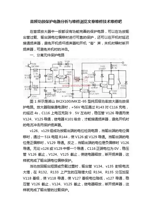
一、分离元件保护电路图1所示是湖山BK2X100JMKⅡ-95型纯后级功率放大器功放保护电路。
放大器刚接通电源时,+56V电压通过R143对C116充电,约延迟4s,C116上电压充到9.5V左右时,稳压管V126导通而使V124、V125导通,继电器K101吸合,才能接通扬声器,避免开机时的电流冲击而保护扬声器。
v126、v129组成功放输出端的电位检测电路,当输出端的电位偏移时,通过一51k电阻R144,使V126或V129导通。
当输出端的电位是正偏移时,V129导通。
反之,当输出端的电位是负偏移时V126导通。
无论v126或V129中哪一个导通,C116正端电位为0V,稳压管V126截止,V124、V125截止,使继电器释放,断开扬声器,这样就完成了输出端电位偏移保护。
当功放因输出短路或负载过重时,输出管V134、v135射极电流大增,在R132、R133上产生的压降增大经R134、R135分压加至V118基极,使V118导通,使V127基极电位降低,v127导通,稳压管V126截止,V124、V125截止,继电器释放,断开扬声器,这样就完成了输出管的过载保护。
二、uPC1237保护电路图2所示是天逸AD-5100A型AV放大器功放保护电路。
J1、J2为接在功放输出端的继电器。
刚开机时,+56V电压经R57、R58对c29充电,几秒后,当C29充电到一定电压时,IC2(uPC1237)⑥脚内的开关电路接通,输出低电平,使J1、J2吸合,接通扬声器,实现开机延时保护功能。
当功放输出端直流电压因某种原因发生偏移,使IC2 2脚电压超过+0.7V,或低于-0.23V时,⑥脚内开关电路截止,输出高电平,使J1、J2释放,断开扬声器,实现功放输出端的直流电压偏移保护。
雅马哈贴片机_修机_调机的经验之谈1 SMT设备维修实例随着电子工业的飞速发展,SMT设备正得到越来越广泛的应用,但这些设备在使用过程中不可避免地会出现这样或那样的问题。
一般情况下使用厂家是与设备供应商联系维修,但往往会因为路途等原因耽误相当长时间而影响生产,而且设备维修花费、维修人员的旅途费等也将是一笔不小的开支。
因此,对于SMT工程技术人员来说,掌握一定的维修技术,就可以避免上述情况的出现。
在维修过程中,我们应找出设备故障产生的根本原因,这样我们在排除故障时才能做到有的放矢。
笔者将结合自己的几次维修典型事例,介绍SMT设备故障分析及排除方法,以供同行参考。
故障分析及排除故障一:托盘(TRAY)元件供料平台位置的调整工作过程:我们使用的高精度贴片机为松下MPA—G3,其托盘元件供料器与机器主体连为一体。
贴装托盘元件(如QFP)时,有一个专用吸头(TRAY HEAD)将元件从托盘中吸出并放在一个供料平台上,然后供料平台移到贴片头所在位置以供贴装头吸取贴装。
故障的产生及分析:我们发现贴装头(MOUNT HEAD)吸取元件时存在一定的偏差,吸嘴很难吸取到元件的正中心上,从而会对贴装造成一定的影响。
但若将机器工作方式改为直接取料,即MOUNT HEAD不通过供料平台而直接从托盘上吸取元件时,就不存在这种情况。
由此我们分析MOUNT HEAD与TRAY HEAD在供料台上吸取放置元件的位置不在一个轴上,从而造成吸取误差。
故障的排除:MOUNT HEAD与TRAY HEAD在供料平台上的吸取放置元件的位置可由机器参数(MACHINE DATA)来设定,我们以MOUNT HEAD在供料平台上吸取元件的位置为参考点,将TRAY HEAD在供料平台上放置元件的位置调整到与参考点位置重合即可。
在以后的生产过程中,就再未出现过托盘元件吸取不正的问题。
笔者利用这种方法也曾解决了另外一家单位设备中存在的相类似的问题。
故障二:部品贴装偏差大故障的产生:笔者曾使用过YAMAHA公司的中速贴片机YV1OO,该型机器以贴装片状元件为主。
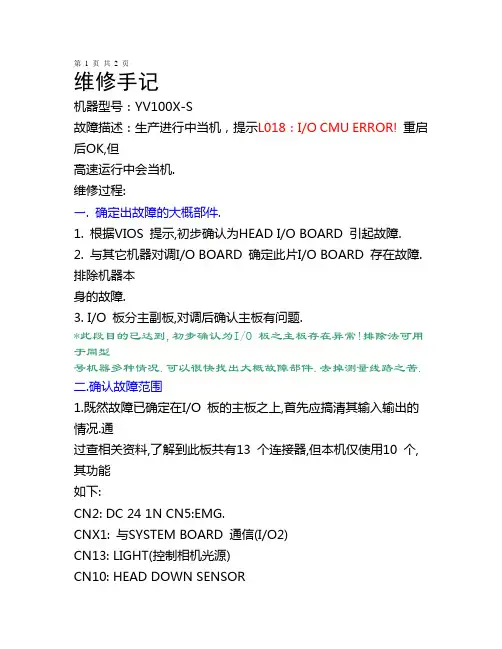
第 1 页共2 页维修手记机器型号:YV100X-S故障描述:生产进行中当机,提示L018:I/O CMU ERROR! 重启后OK,但高速运行中会当机.维修过程:一. 确定出故障的大概部件.1. 根据VIOS 提示,初步确认为HEAD I/O BOARD 引起故障.2. 与其它机器对调I/O BOARD 确定此片I/O BOARD 存在故障.排除机器本身的故障.3. I/O 板分主副板,对调后确认主板有问题.*此段目的已达到,初步确认为I/O 板之主板存在异常!排除法可用于同型号机器多种情况.可以很快找出大概故障部件.去掉测量线路之苦.二.确认故障范围1.既然故障已确定在I/O 板的主板之上,首先应搞清其输入输出的情况.通过查相关资料,了解到此板共有13 个连接器,但本机仅使用10 个,其功能如下:CN2: DC 24 1N CN5:EMG.CNX1: 与SYSTEM BOARD 通信(I/O2)CN13: LIGHT(控制相机光源)CN10: HEAD DOWN SENSORCN8: SL. DOWN SENSORCN7: DOWN HEADCN4: R.UP / DOWN / SAFATY SENSORCN9: VACUUM SENSOR可以看出唯一与外界通信的是CNX1 ,现在仅插X1 开机.自检OK.归零OK.到3/3/B5,MOVE RANDOM→X1→100→RUN. 3S 后当机,重复二次依然出现相同故障.依此判定其余未插的连接器不存在问题.现重点排查这4 个连接器是否存在接触不良的问题.X1 不太可能存在接触不良,因为它在副板上,再用排除法一一拨掉4.开机,均有故障出现.但不是L018.排除中不小心手碰了一下机板.突然发现副板上的5VLED 闪了一下.再碰,发现LED 有闪断的现象.是否可能为主/副板连接器接触不良呢?3.连接不良?清洁!无效;更换?找不到配件.只有使用最狠的一招.用线直接焊!60*2=120 30 分钟后完成!装好之后,竟然故障依旧!!!第 2 页共2 页4.排除此连接器的问题,还原连接器!5.在第2 步排除掉5,唯独没排除CN2. CN2 怎么排除?焊上去啰!在操作时由于晕了头未关电就顺手拨下CN2 了,不经意发现屏幕显示L018 !!!莫非电源部分有问题.7.联想到碰.高速会当机,会不会是由于在剧烈情况下电源部份的元件的瞬间接触不良而产生的呢?8.当I/O 板正常时,D23 常亮D22 启动前慢闪,启动OK 后快闪.LED2 常亮.9.取下机板分析.此板电源部份组件不多,将组件焊点加锡一遍后故障依旧.测量元件.经对比后也没发现有什么问题.10.转到正面,取下X1 (小心,此东东比较难拆). 发现在它的掩盖之后还有一个二极管.太小,本人近视,用放大镜观察,终于发现传说中的假焊.此发现纯属巧合,鬼子的东西也有假焊??加锡焊接先!11.装机,开机,祈祷,启动OK!归零OK!! 3/3/B5 正常.运行10 分钟OK!12.初出判定故障排除!三.总结1.解决此问题还有一个办法.就是换I/O 板!2.充分运用排除法,操作中胆大心细!3.具体操作中要一步步做好相关记录!。
DA CONVERTER Owner’s ManualEKeep This Manual For Future Reference.FCC INFORMATION (U.S.A.)1. IMPORTANT NOTICE: DO NOT MODIFY THIS UNIT!This product, when installed as indicated in the instructions contained in this manual, meets FCCrequirements. Modifications not expressly approved by Yamaha may void your authority, granted by the FCC, to use the product.2. IMPORTANT: When connecting this product to accessories and/or another product use only high quality shielded cables. Cable/s supplied with this product MUSTbe used. Follow all installation instructions. Failure to follow instructions could void your FCC authorization to use this product in the USA.3. NOTE: This product has been tested and found to comply with the requirements listed in FCC Regulations, Part 15 for Class “B” digital devices. Compliance withthese requirements provides a reasonable level of assurance that your use of this product in a residential environment will not result in harmful interference with other electronic devices. This equipment generates/uses radio frequencies and, if not installed and used according to the instructions found in the users manual, may cause interference harmful to the operation of other electronic devices. Compliance with FCC regulations does not guarantee that interference will not occur in all installations. If this product is found to be the source of interference, which can be determined by turning the unit “OFF” and “ON”, please try to eliminate the problem by using one of the following measures:Relocate either this product or the device that is being affected by the interference.Utilize power outlets that are on different branch (circuit breaker or fuse) circuits or install AC line filter/s.In the case of radio or TV interference, relocate/reorient the antenna. If the antenna lead-in is 300 ohm ribbon lead, change the lead-in to coaxial type cable.If these corrective measures do not produce satisfactory results, please contact the local retailer authorized to distribute this type of product. If you can not locate the appropriate retailer, please contact Yamaha Corporation of America, Electronic Service Division, 6600 Orangethorpe Ave, Buena Park, CA 90620The above statements apply ONLY to those products distributed by Yamaha Corporation of America or its subsidiaries.WARNING: THIS APPARATUS MUST BE EARTHEDIMPORTANTTHE WIRES IN THIS MAINS LEAD ARE COLOURED INACCORDANCE WITH THE FOLLOWING CODE:GREEN-AND-YELLOW : EARTHBLUE : NEUTRALBROWN : LIVEAs the colours of the wires in the mains lead of this apparatus maynot correspond with the coloured markings identifying the terminals inyour plug, proceed as follows:The wire which is coloured GREEN and YELLOW must beconnected to the terminal in the plug which is marked by the letter Eor by the safety earth symbol or coloured GREEN and YELLOW.The wire which is coloured BLUE must be connected to the terminalwhich is marked with the letter N or coloured BLACK.The wire which is coloured BROWN must be connected to theterminal which is marked with the letter L or coloured RED.* This applies only to products distributed by YAMAHA KEMBLEMUSIC (U.K.) LTD.i Important InformationPlease read before operating the DA824Warnings•Do not subject the DA824 to extreme temperatures, humidity, direct sunlight, or dust, which could be a potential fire or electrical shock hazard.•Do not allow water to enter the DA824 or allow it to become wet. Fire or electrical shock may result.•Connect the power cord only to an AC outlet of the type stated in this Owner’s Manual or as marked on the DA824. Failure to do so is a fire and electrical shock hazard.•Hold the power-cord plug when disconnecting from an AC outlet. Never pull the cord.A power cord damaged through pulling is a potential fire and electrical shock hazard.•Do not touch the power plug with wet hands. Doing so is a potential electrical shock hazard.•Do not place heavy objects, including the DA824, on top of the power cord. A damaged power cord is a fire and electrical shock hazard. In particular, be careful not to placeheavy objects on a power cord covered by a carpet.•Do not scratch, bend, twist, pull, or heat the power cord. A damaged power cord is a fire and electrical shock hazard.•If the power cord is damaged (e.g., cut or a bare wire is exposed), ask your dealer for a replacement. Using the DA824 with a damaged power cord is a fire and electrical shockhazard.•Do not plug several devices into the same AC outlet. This may overload the AC outlet, and could be a fire or electrical shock hazard. It may also affect the performance of someequipment.•If you notice any abnormality, such as smoke, odor, or noise, or if a foreign object or liquid gets inside the DA824, turn it off immediately. Remove the power cord from theAC outlet and consult your dealer for repair. Using the DA824 in this condition is a fireand electrical shock hazard.•Do not place small objects on top of the DA824. Metal objects falling inside the DA824 is a fire and electrical shock hazard.•If a foreign object or water gets inside the DA824, turn it off immediately. Remove the power cord from the AC outlet and consult your dealer for repair. Using the DA824 inthis condition is a potential fire and electrical shock hazard.•Should the DA824 be dropped or the cabinet be damaged, turn off the power, remove the power plug from the AC outlet, and contact your dealer. If you continue using theunit without heeding this instruction, fire or electrical shock may result.•Do not remove the DA824’s cover. Y ou could receive an electrical shock. If you think internal inspection, maintenance, or repair is necessary, contact your dealer.•Do not attempt to modify the DA824. This is a potential fire and electrical shock haz-ard.•Do not block the DA824 ventilation slots. Blocking the ventilation slots is a potential fire hazard.DA824—Owner’s ManualiiCautions•Allow enough free space around the unit for normal ventilation. This should be: 10 cm at the sides, 15 cm behind, and 30 cm above. These distances should also be adoptedwhen rack-mounting the DA824. For normal ventilation during use, remove the rearof the rack or open a ventilation hole. If the airflow is not adequate, the DA824 will heatup inside and may cause a fire.•Use the DA824 in an environment where the temperature is between 10˚C and 35˚C (50˚F and 95˚F).•Turn off audio devices when connecting them to the DA824, and use only the cables specified in the relevant owner’s manuals.•If you plan not to use the DA824 for a long period of time, remove the power cord from the AC outlet. Leaving the DA824 connected is a potential fire hazard.•Do not use benzene, thinner, cleaning detergent, or a chemical cloth to clean the DA824. Use only a soft, dry cloth.•If the DA824 is stored in a cold place (e.g., overnight in a car), and then moved to a warmer environment, or the temperature rises sharply, condensation may form insidethe DA824, which may affect performance. In such cases, the DA824 should be allowedto acclimatize for about one hour before use.InterferenceThe DA824 uses high-frequency digital circuits that may cause interference on radioand television equipment located nearby. If interference is a problem, relocate theaffected equipment.DA824 Exclusion of Certain ResponsibilityManufacturer, importer, or dealer shall not be liable for any incidental damages includ-ing personal injury or any other damage caused by improper use or operation of theDA824.Y amaha cannot be held responsible for any loss of data or data damage due to improperuse or operation of the DA824.Package ContentsThe DA824 package should contain the following items. Contact your Y amaha dealer ifanything is missing.•DA824 DA Converter•This manualTrademarksADAT MultiChannel Optical Digital Interface is a trademark of Alesis Corporation.Tascam Digital Interface is a trademark and Tascam and T eac are registered trademarksof T eac Corporation. Y amaha is a trademark of Y amaha Corporation. All other trade-marks are the property of their respective holders and are hereby acknowledged.DA824—Owner’s ManualiiiCopyrightNo part of the DA824 software or this Owner’s Manual may be reproduced or distrib-uted in any form or by any means without the prior written authorization of Y amaha Corporation.© 2000 Y amaha Corporation. All rights reserved.DA824—Owner’s Manualiv ContentsContents1Introduction . . . . . . . . . . . . . . . . . . . . . . . . . . . . . . . . 1 Welcome . . . . . . . . . . . . . . . . . . . . . . . . . . . . . . . . . . . . . . . . . . . . . . . . . . . . . . . . . . . 1Installation . . . . . . . . . . . . . . . . . . . . . . . . . . . . . . . . . . . . . . . . . . . . . . . . . . . . . . . . . 1Setting the Maximum Output Level . . . . . . . . . . . . . . . . . . . . . . . . . . . . . . . . . . . . 1Connecting the Power Cord . . . . . . . . . . . . . . . . . . . . . . . . . . . . . . . . . . . . . . . . . . . 1Turning On the Power . . . . . . . . . . . . . . . . . . . . . . . . . . . . . . . . . . . . . . . . . . . . . . . 1 2Touring the DA824 . . . . . . . . . . . . . . . . . . . . . . . . . . . 2 Front Panel . . . . . . . . . . . . . . . . . . . . . . . . . . . . . . . . . . . . . . . . . . . . . . . . . . . . . . . . . 2Rear Panel . . . . . . . . . . . . . . . . . . . . . . . . . . . . . . . . . . . . . . . . . . . . . . . . . . . . . . . . . . 3 3Digital I/O Cards . . . . . . . . . . . . . . . . . . . . . . . . . . . . . 4 About Digital I/O Cards . . . . . . . . . . . . . . . . . . . . . . . . . . . . . . . . . . . . . . . . . . . . . . 4Card Specifications . . . . . . . . . . . . . . . . . . . . . . . . . . . . . . . . . . . . . . . . . . . . . . . . . . 4Installing I/O Cards . . . . . . . . . . . . . . . . . . . . . . . . . . . . . . . . . . . . . . . . . . . . . . . . . . 5 4Hookup Examples . . . . . . . . . . . . . . . . . . . . . . . . . . . . 6 Basic AES/EBU Connection . . . . . . . . . . . . . . . . . . . . . . . . . . . . . . . . . . . . . . . . . . . 6Basic ADAT Connection . . . . . . . . . . . . . . . . . . . . . . . . . . . . . . . . . . . . . . . . . . . . . . 6AES/EBU Connection with Splitter Cable . . . . . . . . . . . . . . . . . . . . . . . . . . . . . . . 7Dual ADAT Connection . . . . . . . . . . . . . . . . . . . . . . . . . . . . . . . . . . . . . . . . . . . . . . 7 5Wordclocks . . . . . . . . . . . . . . . . . . . . . . . . . . . . . . . . . 8 About Wordclocks . . . . . . . . . . . . . . . . . . . . . . . . . . . . . . . . . . . . . . . . . . . . . . . . . . . 8Wordclock Hookup Examples . . . . . . . . . . . . . . . . . . . . . . . . . . . . . . . . . . . . . . . . . 8Wordclock Termination . . . . . . . . . . . . . . . . . . . . . . . . . . . . . . . . . . . . . . . . . . . . . . 9Appendix . . . . . . . . . . . . . . . . . . . . . . . . . . . . . . . . . . . 10Specifications . . . . . . . . . . . . . . . . . . . . . . . . . . . . . . . . . . . . . . . . . . . . . . . . . . . . . . . 10Dimensions . . . . . . . . . . . . . . . . . . . . . . . . . . . . . . . . . . . . . . . . . . . . . . . . . . . . . . . . 12 DA824—Owner’s ManualIntroduction1DA824—Owner’s Manual2Chapter 2—Touring the DA824DA824—Owner’s ManualRear Panel3DA824—Owner’s Manual4 Chapter 3—Digital I/O CardsDA824—Owner’s Manual 3 Digital I/O CardsAbout Digital I/O CardsFor digital input, the DA824 uses optional mini YGDAI (Y amaha General Digital Audio Interface) cards, which are available in all the popular digital audio interconnect for-mats, including AES/EBU, ADAT, and Tascam TDIF-1.The following digital I/O cards are currently available. See the Y amaha Professional Audio Web site at the following address for up-to-date news on mini YGDAI cards: <http://www.yamaha.co.jp/product/proaudio/homeenglish/>.MY8-AT—ADATThe MY8-AT card provides ADAT format digital I/O via two MultiChannel Optical Digital Interface connectors, and supports 16-, 20-, and 24-bit wordlengths. MY8-AE—AES/EBUThe MY8-AE card provides AES/EBU format digital I/O via a 25-pin D-sub connector, and supports 16-, 20-, and 24-bit wordlengths.MY8-TD—Tascam TDIF-1The MY8-TD card provides Tascam TDIF-1 format digital I/O via a 25-pin D-sub con-nector, and supports 16-, 20-, and 24-bit wordlengths. A BNC connector is provided for wordclock output.MY8-TD cards feature a device selector switch (EXT: 88/INT: 38) that should be set to match the device being connected. This should be set to “EXT: 88” when connecting a Tascam DA-88, or “INT: 38” when connecting a Tascam DA-38, DME32, or other device.Card SpecificationsThe following table provides specifications for the DA824-compatible I/O cards. CardFormat In Out Wordlength ConnectorsMY8-ATADAT I/O 8816, 20, 24Optical x2MY8-AEAES/EBU I/O 8816, 20, 2425-pin D-sub (cable not included)MY8-TD Tascam TDIF-1 I/O 8816, 20, 2425-pin D-sub,BNC wordclock outInstalling I/O Cards5DA824—Owner’s Manual6Chapter 4—Hookup ExamplesDA824—Owner’s ManualAES/EBU Connection with Splitter Cable7DA824—Owner’s Manual8Chapter 5—WordclocksDA824—Owner’s ManualWordclock Termination9DA824—Owner’s Manual10AppendixDA824—Owner’s ManualAppendixSpecificationsSampling rateMY8-AE, MY8-TD 39.69–50.88 kHz MY8-AT41.013–50.88 kHzDA conversion resolution 24-bit linear, 128-times oversampling Frequency response –3, +1 dB, 20 Hz–20 kHz Dynamic Range 11.Measured with a 6 dB/octave filter at 12.7 kHz; equivalent to a 20 kHz filter with infinitedB/octave attenuation.110 dB (typical)Gain Error ±1 dB @ 1 kHz THD 22. 6 dB/octave filter @ 80 kHz.*Where dB represents a specific voltage, 0 dB is referenced to 0.775 V rms, 0 dBV is refer-enced to 1.00 V rms.0.05%, 20 Hz–20 kHz0.01% full scale output @ 1 kHz Hum & Noise Level 1–92 dB (typical)Crosstalk –70 dB between adjacent channels @ 1 kHz Signal Delay0.57 ms (digital input to analog output, fs = 48 kHz)IndicatorsPEAK 3 dB below full scale NOMINAL14 dB below full scale SIGNAL 34 dB below full scale LOCK Wordclock lock POWERPower on/offPower requirements U.S.A. & Canada 120 V AC, 60 Hz Europe 230 V AC, 50 Hz Power consumption 40 WDimensions (W × H × D)480 × 97.5 × 366.8 mm (18.9 x 3.84 x 14.44 inches)Weight7.5 kg (16.53 lbs)Free-air operating temperature 10˚ C to 35˚ C (50˚ F to 95˚ F)Storage temperature –20˚ C to 60˚ C (–4˚ F to 140˚ F)Power cord length 1.9 mSupplied AccessoriesOwner’s ManualSpecifications11DA824—Owner’s ManualAnalog OutputDigital I/OConnectionGAIN SWActual Source ImpedanceFor Use with NominalOutput Level ConnectorNominal Max. before clip OUTPUT 1–811.24-bit 128-times oversampling D/A converters.+24 dB 150 Ω lines600 Ω lines+10 dB (2.45 V)+24 dB (12.28 V)XLR-3-32 type (balanced)2&TRS phonejack (balanced)32.XLR-type connectors are electronically balanced (pin 1= ground, pin 2= hot, pin 3= cold).3.TRS phone jacks are electronically balanced (tip= hot, ring= cold, sleeve= ground).*Where dB represents a specific voltage, 0 dB is referenced to 0.775 V rms, 0 dBV is refer-enced to 1.00 V rms.+18 dB+4 dB (1.23 V)+18 dB (6.16 V)+15 dB +1 dB (0.87 V)+15 dB (4.36 V)+4 dBV–10 dBV (0.316 V)+4 dBV (1.58 V)Connection Format Level/ImpedanceConnector COM—RS232C 9-pin D-sub (male)WORD CLOCK IN —TTL, 75Ω (ON/OFF)BNC WORD CLOCK THRU —TTL, 75ΩBNC SLOTmini YGDAI——12AppendixDA824—Owner’s ManualYAMAHA CORPORATION V554060 R0 1 IP 20Pro Audio Division, #18/3P.O. Box 3, Hamamatsu, 430-8651, Japan 00 03 500 AP Printed in Japan。
通用2.1声道有源音箱电路图分析及维修方法(转)一、电源电路(图纸的最下面部分):220V市电经过保险管(F),和开关S后进入变压器初级,变压器的次级输出双12V交流,双12V送入由VD1组成的桥式整流电路电路,经过桥式整流和C14,C15(3300UF/25V)的滤波后,输出的空载电压约为正负16V左右(根号2乘于12V),即A+为正16V,A-为负16V。
正负16V为三块功放芯片TDA2030,UTC2030提供电源。
另一路经过R21、R22的降压后,由B+,B-输出约正负12V为低音前置放大和低通滤波器IC4提供电源电压。
在本图纸当中,前置放大的供电并没有采用78/7912三端稳压电路,磨机爱好者在更换两个3300UF电容时,也可以考虑加入LM7812/7912为前置提供更为稳定的工作电压。
二、左右声道放大电路(卫星箱功放电路),因左右声道作原理完全一致。
这里我只以图纸的左声道为例,作个介绍。
如图:RIN为信号输入端,经过耦合电容C23进入音量电位器,(音量电位器由三个引脚,与C23连接的是输入端,输出端也叫滑动端、另一引脚为接地端),调整音量后信号进入由R1/C3组成的高音提升电路,此电路可以提升一定量的高频信号,使声音更加清晰。
尔后信号经过耦合电容C1进入左声道功放,型号为UTC2030的1脚,经过功率放大后,由2030的第四脚输出,推动卫星箱发声。
图中的R7为反馈电阻,R7/R9为决定2030芯片的放大倍数。
因此,调整R7的阻值,就可以调整放大倍数。
R11/C7为扬声器补偿网络。
三、超低音电路。
由左右声道经两个10K电阻R5、R6后至C11耦合电容,尔后信号进入IC4,型号为JRC4558的3脚,图中IC4A为超低音的前置放大器。
R201T将此放大器的放大倍数设置为6倍左右。
(R17/R18),经过前置放大后,才能保证足够大的驱动电压,获得足够大的音量。
4558的1脚为前置输出,经R19后进入由IC4B、C9、C10、R20组成的低通滤波器。
YAMAHA维修手册一.夹板气缸不能回收机型:YV100-X 拉别:L19 日期:10月20日处理时间:20:45~21:23 故障现象:贴装一块PCB板完成后,在传送过程中报警,报警现象如下图所示:原因分析:1.经检查发现PCB板贴装完毕后没有到达出板感应器位置2.发现夹板气缸只能夹住PCB板,不能自动松开导致传送报警3.经检查确认后为夹边气缸坏解决方法:1.把坏的夹边气缸上三颗螺丝用2.5mm六角卸下来,用手把气缸尾部上的气管拔掉如下图所示:拔掉2.把新的夹边气缸用2.5mm 六角装上三颗螺丝回原位,再用手将气管插入气缸尾部如下图所示:插入装回3.安装完毕后进入手动模式,光标移动到EDGE CLAMP处按多几次ENTER键,使夹边气缸来回顺畅为标准如下图所示:二.吸嘴真空报警机型:YV100-X 拉别:L21 日期:10月22日处理时间:14:00~14:10 故障现象:机器自动运行取料时出现真空报警,报警现象如下图所示:原因分析:1.吸嘴上可能有元件没有被抛弃2.吸嘴堵塞3.经检查后发现吸嘴孔有灰尘,堵塞了吸嘴,确认为吸嘴堵塞解决方法:1.进入I/O命令将吸嘴下降“1为UP”“0为DOWN”如下图所示:2.用专用十字螺丝刀,把2.4.6.8号吸嘴头组件上的两颗螺丝卸下,再用手把1.3.5.7号头上的吸嘴拔下如下图所示:拔下组件2颗螺丝3.将卸下的吸嘴放入酒精盒清洗,并用飞枪吹干如下图所示:1.将清洁干净的吸嘴按照卸下吸嘴的反顺序安装回机器上,注意飞行嘴的安装,组件上的小圆点要和齿轮上的小圆点相对应如下图所示:齿轮圆点组件圆点2.进入真空检测的步骤如下图所示:3.将安装好的吸嘴进行真空测试,得出的数据保存后退出,此机器便可正常生产如下图所示:三.贴装漏料、更换电磁阀机型:YV100-X 拉别:L21 日期:10月25日处理时间:14:30~14:40 故障现象:贴装元件时在炉后面发现有漏料的PCB板,如下图所示:原因分析:1.吸嘴上有一定的粘合物把贴装后的元件又带回取料位置2.真空不足3.经最后发现为产生真空的电磁阀坏,在工作中真空出现时有时无的现象,导致了贴装漏料解决方法:1.把机器的主气源关闭,如下图所示:关闭2.用小号十字螺丝刀,把真空电磁阀上的24V插头拔下,并卸下两颗螺丝如下图所示:插头螺丝3.将新的电磁阀上的密封圈安装好,如下图所示:密封圈4.把安装好密封圈的新电磁阀装回真空摸块上,锁紧两颗螺丝并将24V插头插好如下图所示:插头螺丝5.将关闭的气源打开,并测试真空得出的数据要保存,便可正常生产如下图所示:。
一般技术规格模数/数模转换20Hz-20kHz(全部旁路)动态范围80dB(典型)全谐波失真小于0.1%(1kHz,最大电平)模数/数模转换模数转换16比特数模转换16比特采样频率44.1kHz储存程序99效果程序立体声混响、混响、混响加门、延迟、延迟+混响,混响-镶边,合唱+混响,交响乐+混响输入连接口PHONE JACK×2正常电平-20dB(输入电平标称)阻抗20kΩ(单声道:10kΩ)输出连接口PHONE JACK×2正常电平-20dB(输入电平正常)阻抗2kΩ(单声道:1kΩ)显示七段LED发光二极管×2(显示程序号)前面板控制部分输入电平,混音平衡,延迟衰减,电平前面板键部分▲,▼,MIDI,储存LED发光二极管显示器峰值,左右,延迟,衰减,电平(可编辑目录)MIDI输入5-Pin DIN电源直流12V输入尺寸(宽×高×厚)480×232×45.5mm(18.9″×9.1″×1.8″)重量2.5kg电源适配器美国加拿大:PA-1BU(120V AC)一般:PA-1BU(220V/240V AC)英国:PA-1(240V AC)详细使用说明:一、正确安装和连接YAMAHA--- REV100。
如使用单声道可只接左声道。
INPUT LEVEL:输入电平旋钮,调节此旋钮使峰值指示灯在正常工作时偶尔闪亮。
一直闪亮表示信号过强,声音会削波,过弱又会发生音质下降,因此调节适当的电平输入是使用好效果器的第一步,也是很重要的一步。
MIX BALANCE:效果混合旋钮,用来调节效果声和原声之间的比例。
PROGRAM:用来选择不同的程序,编辑程序存储。
二、改变效果程序:YAMAHA—REV100共有99种效果程序,用上下光标键选择。
混响程序名类型说明01 Vocal rev1 人声适用于人声混响02 Vocal rev2 大厅3号程序的前期延长,混响时间短03 Vocal rev3 人声04 Room ambience1 盘子04-08这些效果适用于鼓和打击乐音色,可作用于整个鼓组或某个鼓音色05 Room ambience2盘子06 Room ambience3盘子07 Wood booth1 人声08 Wood booth2 人声09 Acoustic piano plate 用于钢琴的混响10 Club piano 大厅用于钢琴的混响11 Booming kick1大厅用于底鼓的混响,强调低频12 Booming kick2 房间用于底鼓的混响,强调低频13 Loud snare房间用于军鼓的混响14 Acoustec steel guitar1 盘子钢弦原声吉它的混响15 Acoustec steel guitar2 盘子钢弦原声吉它的混响16 String plate 盘子弦乐的混响17 Acoustec gut guitar1 人声尼龙弦原声吉它混响18 Acoustec gut guitar2 人声尼龙弦原声吉它混响19 Btass room1 房间铜管乐器的混响20 Btass room 房间铜管乐器的混响立体声混响程序名类型说明21 Large hall1 大厅Stage比hall的混响更明亮22 Large hall2 大厅Stage比hall的混响更明亮23 Stage1 大厅Stage比hall的混响更明亮24 Stage2 大厅Stage比hall的混响更明亮25 Chamger1 人声模拟大房间,高顶的混响26 Chamger2 大厅模拟大房间,高顶的混响27 Church1 房间模拟大房间,高顶的混响28 Church2 大厅模拟大房间,高顶的混响29 Old gunnel 大厅模拟长通道中的混响,old暗、new明亮30 New tunnel 人声31 Large room1 房间房间混响,32比31低频更多32 Large room2 房间33 Slide reverb 房间混响的声像在右34 Huge room1 房间比房间混响更有力的混响35 Huge room2 房间比房间混响更有力的混响36 Bathroom 盘子短立体声的混响37 String ensemble 盘子用于弦乐的大混响38 Rude reverb1 人声粗混响39 Rude reverb2 人声粗混响40 Comcert grand piano 人声用于原钢琴的混响门混响程序名类型说明41 Small ambience1 大厅小房间反射混响,42比41的低频少42 Small ambience2 大厅43 Tight poom1 房间比上面两种效果更小的混响44 Tight poom 大厅比上面两种效果更小的混响45 Gate reverb1 盘子各种门混响46 Gate reverb2 人声各种门混响47 Gate reverb3 大厅各种门混响48 Gate reverb4 大厅各种门混响49 Stone room 房间石头房间混响50 Big curve 人声最长的门混响延迟程序名说明51 Analog delay1 软延迟52 Ping pong delay 声像左右变化的延迟53 Eighth note triplet 像8分三连音符的延迟54 Karaoke 用于卡拉OK的回声效果55 Short delay doubler 一次短的延迟56 Stereo long delay 左右声道同长的立体声延迟57 Sgereo medium delay 左右声道不等长的立体声延迟58 Stereo long delay 左右声道同长的短延迟59 Mono long delay 单声道输出的重复延迟60 Mono short delay 单声道输出的重复延迟延迟/混响程序名类型说明61 Electric piano 延迟+大厅常用于钢琴62 String pad 延迟大厅常用于背景音乐63 Synth 延迟人声用于弦乐背景64 Vocal1 64、65是用短延迟的长混响,适用于人声65 Vocal2 延迟大厅64、65是用短延迟的长混响,适用于人声66 Vocal3 延迟房间66是强调延迟的短混响67 Btinght vocal 延迟盘子有小延迟的亮混响68 Chorus 延迟+盘子一半混响,一半延迟69 Drum kit1 延迟+ 房间用于鼓和打击乐的混响70 Drum kit2 延迟盘子用于鼓和打击乐的混响混响/调制程序名类型说明71 Soft flange1 大厅+飘忽此效果结合了混响和小音高变化的飘忽,常用于合成音色背景音乐72 Soft flange2 大厅+飘忽此效果结合了混响和小音高变化的飘忽,常用于合成音色背景音乐73 Amgience flange1 房间飘忽短混响加飘忽74 Amgience flange2 房间飘忽短混响加飘忽75 Soft reverb flange 房间飘忽短混响加音高变化更大的飘忽76 Organ cabinet1 盘子飘忽用于风琴的飘忽效果77 Organ cabinet2 房间交响用于风琴的飘忽效果78 Symphonic reverb1 大厅+交响以混响为主的精致效果79 Symphonic reverb2 人声+交响以混响为主的精致效果80 Flange room1 房间+飘忽为鼓和打击乐加特效81 Flange room2 房间+飘忽为鼓和打击乐加特效82 Rolling flange1 盘子+飘忽为鼓和打击乐加特效83 Rolling flange2盘子+飘忽为鼓和打击乐加特效84 Big flange 人声飘忽喷气机效果85 Chorus rererb1 大厅+合唱85,86是普通的混响+合唱,用途很广如用于钢琴86 Chorus reverb2 盘子+合唱87 Chorus reverb3 大厅+和唱88 Chorus reverb4 人声+合唱89 Tremolo reverb1 大厅+震音震音+混响的各种变化效果90 Tremolo reverb2 大厅震音震音+混响的各种变化效果91 Tremolo reverb3 盘子+震音震音+混响的各种变化效果92 Tremolo reverb4 人声+震音震音+混响的各种变化效果93 Tremolo reverb5 人声+震音震音+混响的各种变化效果94 Tremolo reverb6 大厅+震音震音+混响的各种变化效果95 Tremolo reverb7 大厅+震音震音+混响的各种变化效果96 Ambient slow pan1大厅+震音左右声像变化和短混响97 Ambient slow pan2 房间+震音左右声像变化和短混响98 Sequence pan1房间+震音根据乐曲速度而定的声像变化效果99 Sequence pan2房间+震音根据乐曲速度而定的声像变化效果编辑模式(Edit Mode)REV100的每个效果都具有多个参数,3个主要参数可通过面板上的旋钮控制。
功放维修手册一、整机不工作整机不工作的故障表现为通电后放大器无任何显示,各功能键均失效,也无任何声音,像未通电时一样。
检修时首先应检查电源电路。
可用万用表测量电源插头两端的直流电阻值(电源开关应接通),正常时应有数百欧姆的电阻值。
若测得阻值偏小许多,且电源变压器严重发热,说明电源变压器的初级回路有局部短路处;若测得阻值为无穷大,应检查保险丝是否熔断、变压器初级绕组是否开路、电源线与插头之间有无断线。
有的机器增加了温度保护装置,在电源变压器的初级回路中接人了温度保险丝(通常安装在电源变压器内部,将变压器外部的绝缘纸去掉即可见到),它损坏后也会使电源变压器初级回路开路。
若电源插头两端阻值正常,可通电测量电源电路各输出电压是否正常。
对于采用系统控制微处理器或逻辑控制电路的放大器,应着重检查该控制电路的供电电压(通常为+5V)是否正常。
如无+5V电压,应测量三端稳压集成电路7805的输入端电压是否正常,若输人端电压不正常,应检查整流、滤波电路。
若7805输入端电压正常,而输出端无十5V电压或电压偏低,可断开负载看+5V电压能否恢复正常。
若+5V电压正常,则故障在负载电路;若+5V电压仍不正常,则故障在7805本身。
若系统控制电路的+5V供电电压正常,应再检查微处理器的时钟及复位信号是否正常、键控与显示驱动电路有无损坏。
二、无声音输出无声故障表现为操作各功能键时,有相应的状态显示,但无信号输出。
检修有保护电路的放大器时,应看开机后保护继电器能否吸合。
若继电器无动作,应测量功放电路中点输出电压是否偏移、过流检测电压是否正常。
若中点输出电压偏移或过流检测电压异常,说明功率放大电路有故障,应检查正、负电源是否正常。
若正、负电压不对称,可将正、负电源的负载电路断开,以判断是电源电路本身不正常还是功放电路有故障所致。
若正、负电源正常,应检查功放电路中各放大管有无损坏。
若功放电路中点输出电压和过流检测电压均正常,而保护继电器不吸合,则故障在保护电路,应检查继电器驱动集成电路或驱动管有无损坏、各检测电路是否正常。
Yamaha Pw80 Workshop Manual 2004DOWNLOAD HEREALL MODELS & REPAIRS ARE COVERED A-Z! THIS WORKSHOP SERVICE REPAIR MANUAL IS THE REAL DEAL! COVERS ALL REPAIRS A-Z, MECHANICAL & ELECTRICAL! TONS OF DETAILED PICTURES & DIAGRAMS INCLUDED! ALL PAGES ARE PRINTABLE, PRINT OFF ONLY WHAT YOU NEED! BUY FROM US WITH TOTAL CONFIDENCE! SUPER FAST DOWNLOAD DELIVERY ON ALL ORDERS! PROFESSIONAL QUALITY SERVICE & REPAIR MANUALS ALWAYS! USE IT AS MANY TIME AS YOU LIKE! THIS WORKSHOP MANUAL WILL NEVER TIME OUT OR EXPIRE! FAQ: Why should I purchase this Service Repair Workshop Manual? This manual is an easy layout format that covers all repair procedures in great detail. This manual will help you better understand all the parts & repair procedures on your vehicle. With the knowledge contained within this manual, you will easily be able to do your own servicing & repairs. FAQ: What models are covered in this manual? All models for the above stated years and all engine types are included. This Service Repair Workshop Manual is not generic, it is SPECIFIC to the above stated model. Its the same type of Manual that your localDealer/Mechanic would use. FAQ: What type of information is covered? Routine Maintenance, Tune-up Procedures, Specifications, Engine Removal / Installation, Cylinder Head / Valve Train, Engine Block, Engine Lubrication, Intake Manifold / Exhaust System, Cooling and Heating, Fuel and Emissions, Transaxle, Clutch, Manual Transmission, Automatic Transmission, Deferential, Driveshaft, Steering, Suspension, Brakes (including ABS), Body, Heater and Air Conditioning, Automatic Climate Control, Electrical (including SRS), Supplemental Restraint System (SRS), Engine Repair, Air Conditioning, Exhaust, Emissions Control, Ignition, Steering, Wiring Diagrams, Valve Timing Procedures, Chain & Gear Replacement, General Removal & Installation Instructions, Safety Precautions, Special Tools, Tensioner Adjustments, Tightening Torques, Timing Marks, Valve Timing Instructions, Tensioner Release & Reset Methods, Chain Routing & Sprocket/Gear Valve Timing Marks, ETC. FAQ: How long for delivery? Delivery on this item is instant once you have paid with your Credit/Debit/Paypal Account, there is no shipping involved, you will receive this manual right away! You Can Fix It Today! FAQ: How much money will I save? This manual will help you save money upwards into the thousands. Dont be scammed bymechanics charging you tons of money for a small job that you can do yourself using the information & knowledge contained on this manual. FAQ: Is this manual hard to use? No, not at all. If you can open up an email then you can use this manual, its that simple! This manual is in PDF format and will work on any PC/MAC computer using Microsoft Windows. IE: XP, NT, 2000, Vista, Windows 7 EtcDOWNLOAD HERESimilar manuals:1997 Yamaha BANSHEE YFM350X ATV Service Manual1999 -2003 Yamaha XJR MOTORCYCLE Service ManualYamaha WR450FR WR450 WR 450 MOTORCYCLE Workshop Service / Repair ManualYamaha XJ600 Diversion Seca II MOTORCYCLE Workshop Service / Repair ManualYamaha XJ750 XJ750K XJ 750 MOTORCYCLE Workshop Service Repair ManualYamaha XT660R XT660X XT660 MOTORCYCLE Workshop Service / Repair Manual 2004Yamaha FJR1300 MOTORCYCLE Workshop Service / Repair Manual 20011988 - 1990 Yamaha FZR400 Service Shop Workshop RepaYamaha 125 RD Motorcycle Owners ManualYamaha Banshee 350 Service Repair Manual - All YearsYamaha FZR 600 Service Repair Manual PDF All YearsYamaha YZF R1 Service Repair Manual 98-991999 Yamaha XVS1100(L) Service Manual DownloadYamaha YFZ-R1 Service Manual PDF R1 Repair EBook 2000-012004 Yamaha Motorcycle YZF R1 Service Manual Download1998 Yamaha Motorcycle YZF R1 Service Manual Download2003 Yamaha Motorcycle YZF R6 Service Manual Download2004-2005 Yamaha YFZ-450 ATV Workshop Service Repair + Owners Manual2000 Yamaha Waverunner GP 1200R Workshop Service / Repair ManualYamaha Raptor YFM 660 Service Manual Atv Quad1987-2002 Yamaha Banshee YFZ350 ATV Workshop Service, Repair Manuals And Supplementaries1998 - 2004 Yamaha YFM400 ATV Factory Workshop Repair Service ManualYamaha Banshee YFZ350 ATV Workshop Service, Repair Manuals And Supplementaries 1998 - 2001 Yamaha Beartracker YFM250 ATV Workshop Repair Manual1989 - 2001 Yamaha YFS200 Blaster ATV Workshop Service Repair Manual1989 - 2007 Yamaha YFA1 YFM125 Breeze Grizzly ATV Workshop Service Repair Manuals + User's ManualsYamaha XVS 1100 Drag Star 1999 Workshop Service Manual2000 - 2002 Yamaha Waverunner GP 1200R Workshop Service Repair Manual2003 - 2005 Yamaha Waverunner GP1300R Workshop Service Repair Manual1997 - 1999 Yamaha Waverunner GP760 - GP1200 Workshop Service Repair Manual1998 - 2000 Yamaha Waverunner GP800 Workshop Service Repair Manual2001 - 2005 Yamaha Waverunner GP800R Workshop Service Repair Manual2002 - 2006 Yamaha Grizzly YFM660 ATV Workshop Service Repair Manual2003 - 2004 Yamaha YFM400 4WD Kodiak ATV Workshop Service Repair Manual1990 - 1998 Yamaha PZ480 Phazer Snowmobile Workshop Service Repair Manual2001 Yamaha YFM660 Raptor ATV Workshop Service Repair Manual + Parts Views Catalogue 2004 Yamaha YXR660 Rhino ATV Workshop Service Repair Manual1999-2003 Yamaha XV16 Road Star Motorcycle Workshop Service Repair Manual2002 Yamaha XV17 Road Star Warrior Motorcycle Workshop Service Repair Manual1999 - 2007 Yamaha XVZ13 Royal Star + Venture Motrcycle Workshop Service Repair Manual 2000 - 2004 Yamaha Waverunner SUV SV1200 Workshop Service Repair ManualYamaha Xt500 XT 500 SR 500 Sr500 Workshop Service Repair ManualTHE BEST 01-06 Yamaha Raptor 660 ATV Service ManualTHE BEST 03-06 Yamaha Kodiak 450 ATV Service ManualTHE BEST 98-08 Yamaha Grizzly 600 & 660 ATV Service ManualTHE BEST 06-08 Yamaha Raptor 700 ATV Service ManualTHE BEST 06-08 Yamaha Rhino 450 Service ManualTHE BEST 87-06 Yamaha Banshee 350 ATV Service ManualTHE BEST 87-99 Yamaha Big Bear 350 4x4 ATV Service ManualTHE BEST 91-04 Yamaha Warrior 350 ATV Service ManualTHE BEST 96-99 Yamaha Big Bear 350 2x4 Service ManualTHE BEST 99-04 Yamaha Bear Tracker 250 ATV Service ManualTHE BEST 98-05 Yamaha Bruin 250 ATV Service ManualTHE BEST 2007 Yamaha Grizzly 700 ATV Service Manual1996 - 2007 Yamaha Waverunner SJ700 Superjet Workshop Service Repair Manual1999 - 2006 Yamaha TTR250 Motorcycle Workshop Service Repair Manual1988 - 2005 Yamaha XV250 Virago Motorcycle Workshop Service Repair ManualTHE BEST 2003-2006 Yamaha RX1 Snowmobile Series Service ManualYamaha TDM 900 2002-2005 Service Repair Manual TDM900THE BEST 2000-2004 Yamaha GP1200R Waverunner Personal Watercraft Service Manual THE BEST 2003-2008 Yamaha GP1300R Waverunner Service ManualYamaha YZ250 2-strokes Service Repair Manual 2001 2002 2003 2004 2005 2006 Multi Yamaha YZF R6 2003-2005 Service Repair Manual & Parts CatalogueYamaha YZF R6 2008 Service Repair Manual & Parts CatalogueYamaha TTR 250 1999-2006 Service Repair Manual TTR250 TT250RYamaha TT 600 2004-2009 Service Repair Manual TT600Yamaha YZF R6 1999-2002 Service Repair Manual & Parts CatalogueYamaha YZF-R1 2002-2003 Service Repair Manual & Parts Catalogue R1Yamaha YZF-R1 2004-2006 Service Repair Manual R1Yamaha AEROX 50 Manuale Officina Riparazione Catalogo PartiYamaha TDM 900 2002-2005 Manuale Servizio Riparazione Officina TDM900THE BEST 92-97 Yamaha V-Max 4 750/780cc Series Snowmobile Service ManualTHE BEST 89-99 Yamaha Ovation 340 Series Snowmobile Service ManualYamaha XJR 1300 1999-2003 Service Repair Manual XJR1300Yamaha YZ85 2002-2006 Service Repair Manual & MicroficheYamaha YFM700R RAPTOR 700 Service Manual 2005-2008Yamaha Phazer Venture PZ50X PZ50GTX PZ50RTX PZ50MTX PZ50VTX PZ50MPX PZ50WPZ50GTW PZ50FXW PZ50MW PZ50VTW PZ50MPW VK10W Factory Workshop Service Manual 2007-2008 Yamaha YXR70FX 700EFI Rhino Service Repair Workshop Manual. Cheapest On Tradebit.2004, 2005 And 2006 Yamaha Rhino YXR66 660 Service Manual.2003 Yamaha Kodiak YFM400FAR 400 ATV Service Repair Workshop Manual. Cheapest On Tradebit2001 Yamaha YFM660FP Grizzly ATV Service Manual, Instant Download.Yamaha YFZ 450 Service Repair Manual 2003-2006THE BEST 2007 Genuine Yamaha Grizzly 350 IRS ATV Service ManualTHE BEST 1988-2008 Genuine Yamaha YFS200 Blaster ATV Service ManualTHE BEST 1992-1998 Genuine Yamaha Timberwolf 250 2x4 ATV Service ManualTHE BEST 1994-2000 Genuine Yamaha Timberwolf 250 4x4 ATV Service ManualTHE BEST 1997-2000 Genuine Yamaha GP760/GP1200 Waverunner Service ManualTHE BEST 1999-2002 Genuine Yamaha XL1200 LTD Waverunner Service ManualTHE BEST 1995-2005 Genuine Yamaha Wolverine 350 ATV Service ManualYamaha RAPTOR 660 Service Manual 2001-2005Yamaha YFM400 Big Bear 400 Service Manual 2000-2006Yamaha Grizzly 550 700 FI Service Manual 2009-2012Yamaha FZS 600 Fazer Service Manual 1998-2001Yamaha YZF-R6 2006-2007 Manuale Servizio Officina R6 (Italiano)Yamaha YFM350 Grizzly 350 IRS Service Manual 2007-2011Yamaha BR 250 Bravo Snowmobile Service Repair Manual BR250Yamaha YZF R6S 2006-2009 Service Manual & Parts CatalogueTHE BEST 1994-2006 Yamaha Venture/V-Max 600 Series Snowmobile Service Manual 2007 - 2008 Yamaha FX NYTRO Snowmobile Service Repair Workshop Manual2007 - 2008 Yamaha Phazer Venture Snowmobile Service Repair Workshop Manual。
专业功放的维修方法及步骤1.打开机壳别通电左右主板看一遍为了避免故障机通电造成二次损坏,维修时,不要先通电试机。
打开机壳详细查看一下左、右声道主功放板,看是否有管子炸裂、电阻烧焦、保险管烧黑等明显损坏。
2.在路测量功率管大管是否有击穿如果从表面上查看左、右主板无明显损坏,可用指针式万用表Rx1挡在路测量大功率管的集电极与发射极之间是否有短路击穿现象。
NPN -侧用黑表笔接集电极,红表笔接发射极,PNP -侧交换表笔测量。
正常时应是阻值无限大,表针不摆动。
如果机内电容还有存电,表针闪动后会回到原位。
如果表针指示阻值为0Ω或阻值很小,说明功率管有击穿现象。
一般只要一侧功率管有击穿,另一侧功率管很可能也有击穿。
在路测量三极管的三只引脚之间的电阻是检查电路的基本方法,从而不必拆下管子大体判断是否击穿和开路。
用MF47型万用表Rx1挡在路测量大中小功率管的脚间电阻,正常管子测量结果如下:正向测量,大功率管Rbe≈12Ω、Rbc ≈12Ω、Rce=∞(不导通);中功率管Rbe≈15Ω、Rbc≈15Ω,、Rce=∞:小功率管Rbe≈20Ω,Rbc≈20Ω、Rce=∞;反向测量,均不导通。
场效应功率管在路测量除漏极与源极反向测量内部二极管导通外,其余各脚之间应均不导通。
3.所有大管无击穿通电用耳听其间如果经检查没有发现功率管有击穿现象,可通电试机。
开机后用心听机内声音,专业功放一般都设置有保护续电器,而且是每个声道一个,继电器吸合时会发出清脆的“叭嗒”声。
有两次响声说明两个继电器都已经吸合,两路主功放电路基本正常,故障可能在外围输入与输出保护电路。
如果听不出是两个还是一个继电器有动作,可用手指按住继电器后开机。
继电器吸合手指会有振动感。
如果继电器在延迟几十秒后都不吸合,说明主功放电路有故障。
4.大管不会全击穿射极电阻拆一端如果功率管有击穿现象,而且所有管子测量结果都一样。
此时不要一个个都拆,因为一侧的功率管全是并联关系,只要有一个击穿就会形成这样的测量结果。