格栅使用说明书
- 格式:doc
- 大小:654.00 KB
- 文档页数:5
回转式细格栅除污机操作规程宜兴市华电环保设备有限公司目录1、工作原理2、一般性能描述3、性能和结构4、主要技术参数:5、主要材质:6、现场控制箱7、设计、制造及质量控制8、检验与试验要求9、设备的安装、运行、维修手册10、注意事项及维护1、工作原理回转式机械细格栅是一种用于水源口拦除固体垃圾的专用设备,它可以连续自动地清除污水中的各种形状的漂浮物。
当格栅链在减速机驱动机构的驱动下,安工作方向做循环运动,此时水槽中的水流经齿耙栅隙,耙齿格栅对水中的固体杂物进行拦截,并由运动中的耙齿将其捞起,随耙齿链一起向上运行到达顶部后,通过链轮和弯轨的导向,使每组耙齿之间产生相对运动,达到自清目的,致使大部分固态杂物因自身重力而落下,另一些粘附在栅缝中的杂物在反转清洗刷的作用下把耙齿的杂物洗刷干净,并均匀地落入螺旋输送机中。
由于耙齿格栅链是一个封闭式循环机构,所以它可以自动连续地工作,对水中漂浮杂物不断地进行清除。
2、一般性能描述循环耙式清污机适用于原生污水的漂浮物的清除,其主要部件是通常称为“耙齿”或“耙爪”的过滤元件。
整个格栅部件直接安装在渠道上,固体物由滤带捕获,通过耙齿送至格栅驱动装置后部的较高位置后排出。
格栅支架的二侧均固定有混凝土渠道上,并且拆卸方便,格栅在安装过程中保证渠道内的所有污水能全部流经格栅,并且格栅在除污过程中在格栅两侧无死坑。
格栅除污机构在运行中断后一旦恢复运行时,格栅除污机构能在完全阻塞的格栅上去除积聚的栅渣。
机械格栅架、支架及各运动构件均为户外型,所有构件的设计保证在最恶劣的环境中使用寿命最长。
3、性能和结构回转式机械格栅主要由机架、驱动装置(电机减速机)、二侧牵引链、导向链轮、钩形栅片、清扫用转刷及现场控制箱组成。
◆齿耙齿耙是由诸多小齿耙相互联接组成一个硕大的旋转面,捞渣彻底、干净、运转灵活可靠。
齿耙具有足够的强度和刚度,不会造成连接轴的弯曲或影响耙栅平稳移动或脱链。
卸料后的回程耙栅设置实用可靠的卸污吸嘴不会粘附污物。
STEP 1MAKE SURE ALL PARTS HAVE BEEN RECEIVED. IF PARTS ARE MISSING NOTIFY FACTORY IMMEDIATELY.STEP 2READ ALL OF INSTALLATION INSTRUCTIONS BEFORE YOU START.STEP 3MAKE SURE THE OPENING IS THE PROPER SIZE.STEP 4CHECK TO SEE THAT SILL IS LEVEL. If Sill is out of level, mark high Sill level location on low Side Jamb.STEP 5CHECK BOTH LEFT AND RIGHT WALL SURFACES, AND SURFACE AT THE HEAD (ABOVE OPENING)TO ASCERTAINTHAT ALL THREE SURFACES ARE IN LINE AND NO OBJECTSOBSTRUCT THE PROPER INSTALLATION OF :A- WALL ANGLESB- SPRING ASSEMBLYC- THE TRAVEL OF THE CURTAIN.STEP 6 ARE GUIDES YOU RECEIVED SUITABLE FOR THE JAMBS?STEP 7VERIFY THAT GUIDES CAN BE INSTALLED PLUMB.STEP 8LOCATING GUIDE ASSEMBLIES. Locate guide assemblies such that “R” Dimension exists between guides as shown. Bottom of guidesMUST be on a level line and Guides MUST be plumb.STEP 9MASONRY JAMBSHold “Z” guide, or wall angle (“E” guide) against wall and drill mount-ing holes thru the slots. Recheck “R” distance before proceeding.Install wall fasteners.STEP 10 STEEL JAMBS. (Screw Attachment Option)Hold “E” guide against steel jamb and mark the spot to be drilled, orhold wall angle against steel jamb and drill holes thru the slots. Re-check “R” distance before proceeding. Install jamb fasteners.STEP 11 STEEL JAMBS. (Weld Attachment Option)Hold “E” guide against steel jamb and tack weld wall angle in place.Recheck “R” distance before proceeding. Weld using welding elec-trode. All welds must be good quality 3/16” fillet welds. Weld the angleto the steel jamb along the top of the angle.IMPORTANT: When steel jamb does not extend above the opening,use three thru-bolts to fasten each wall angle above the opening.STEP 12IDENTIFY HEADPLATE BRACKETRight Hand Drive shown; Left Hand Drive is opposite.STEP 13 IDENTIFY BARREL ASSEMBLY DRIVE ENDRight Hand Drive shown; Left Hand Drive opposite.STEP 14 ORIENT BARREL AND HEADPLATE BRACKETSSlide Drive End of Barrel Assembly through Drive Bracket Bearingand Tension End through Tension Bracket. Secure Tension Wheel toShaft using Pin or Key.STEP 15 LIFT BRACKETS AND BARREL AND BOLT TO GUIDE WALL AN-GLESWith Forklift or Some Type of Lifting Device Raise Barrel and Brack-ets to Top of Guides. Use Carriage Bolts to fasten Headplate Brack-ets to inside of Guide Wall Angles. Bolt heads are to be on inside ofBrackets. Brackets are to be square to Wall and parallel. Center Bar-rel between brackets. Use a level to make sure Barrel Assembly islevel.STEP 16 DRIVE ASSEMBLYCHAIN HOIST ASSEMBLY.CRANK ASSEMBLY.MOTOR ASSEMBLY.TO BRACKET PLATE TO WALLTHRU WALL CHAINTHRU WALL CRANKSTEP 17 INSTALLATION OF CURTAIN (SLING METHOD)Hang the Curtain on two or more Slings or Heavy Ropes capable ofsuspending the curtain weight. Ropes/Slings MUST be able to sus-pend the Curtain weight. Fasten the Top Slat to the Slings or Ropeswith wire. Rotate the Barrel to bring the Top Slat in place. Center theCurtain between the Headplate Brackets.If the Barrel Assembly has Rings, pull the curtain up and hold the TopSlat against the Rings making sure Curtain is evenly centered onBarrel. Attach Top Slat to Rings with 3/8” Screws and Washersprovided. DO NOT strip Screw Threads.If Barrel Assembly has Studs, the Top Slat will have slots to attach toBarrel. Hook Curtain over Studs and fasten with 5/16” Round HeadScrews and Washers provided.If Slat Segments are provided at the Top of the Curtain, fasten themto Rings or Studs after Curtain is centered. Then crimp the Slat Curladjacent to each Slat Segment.The Sling Method causes less damage than rolling the Curtainonto the Counterbalance while it is on the floor.COMPLETE CURTAIN INSTALLATIONCoil Curtain completely onto Barrel.If Guides are Flared, then install the Middle Angle and OutsideGuide Angles.Place locking pliers on the Guides as shown.Lower Curtain into Guides.Lock the Drive to prevent the Curtain from falling.If the Guides are not flared, install Curtain StopBellmouth onGuides. A Stud is attached to the Guides to hold the Bellmouth. Becertain the back of the Bellmouth is flush against Headplate.STEP 18 APPLYING SPRING TENSI0N.Wind Tension Wheel in the direction shown in figure.Warning this step can be extremely hazardous. Read and understandthis section fully before proceeding.Applying spring tension requires two workers for safety.you will need (2) 1/2” to 5/8” steel rods 2 to 3 feet long (notprovided) to apply tension to the springs. Slide one of theround bars into any of the holes of the tension wheel. Windin the direction the pipe would rotate when the door isgoing up (i.e. adjuster at left, clockwise, adjuster at right, counterclockwise) slide the second round bar in the hole above hold and remove the lower bar. Repeat the procedure until the curtain starts tocoil around the spring assembly and stop when the bottom bar becomes visible. Line up the tension wheel stop with the angle stop andslide the stop round bar provided through stop angle and into the holein the tension wheel. Remove the adjusting bar.STEP 19 INSTALLATION OF CURTAINPlace a pair of vise grips about 4” down from top on both guide. Insertthe ends of the bottom bar into the guide channels, and lower the curtain so that the bottom bar is approximately 4 inches below stop heightuntil the bottom bar rest against the vise grips. Install the two stop bellmouth at front of the guides with the bolts and nuts provided.STEP 20 ADJUST TENSION WITH DOOR IN FULLY OPEN POSITION.Adjust tension one notch at a time to increase or decrease torque asrequired.STEP 21 FINAL CHECKOUT. (TO BE ‘COMPLETED BEFORE INSTALLING HOOD)1. The Guides may be lubricated with a Paste Wax or Silicone Spray.2. Verity thru entire travel of the door that the Endlocks or Windlockson the end of the Curtain are not rubbing the Headplate Brackets.Operate door several times to check for problems.3. Çheck that Bottom Bar is level in full down and full up position andthat Curtain is not binding against back of Guide.4. If Curtain is level at bottom and not level at top, put Shims betweenCurtain and Counterbalance on the low side.STEP 22 HOOD INSTALLATIONIf Hood Supports are provided, snap a line across top of HeadplateBrackets on the Wall. Measure length of Hood Sections and locateHood Support so that Hood Splice will fall on center of Support.Attach Hood to Hood Bands on Bracket Plates (and to Supports if pro-vided) by drilling a 7/32” hole through Hood and Band. Then securewith 1/4” dia. x 3/8” long Self-tapping Screws (five per Bracket and fiveper Support).STEP 1 Install vertical guide rails with attached bracket plates as per spec dimensions.STEP 2 Put pipe into “V” cups, in housing brackets plates.STEP 3 Spin pipe until you see fold of spring around cross member of spring basket, fold should be downwards, if reversed, take off and turn.STEP 4 Spin pipe again, so pin at side of basket is facing downward. Bolt pipes to “V” cups.STEP 5 Slide “S” hooks onto lead slats (as many as spring basket).STEP 6 Raise curtain an attached "S" hooks to cross member of spring basket towards top of basket.STEP 7 Pull down on curtain lightly in order to release holding pin at side of basket.If pin does not release, pull out manually. (Make sure “S” book is secure around cross member of basket).STEP 8 Let curtain wrap around basket then insert into guides.STEP 9 Check tension, if more is needed, turn each spring box one complete revolution clockwise. If less is needed, do the opposite. If one is tomuch and only half is needed, them you must hold spring box withlevel or screw driver to stop spring from unwinding and change the “S”hook to another cross member of the basket either up or down. Whatever adjustment is made to one basket, do to all baskets. Do not put“S” hook on cross members that have the spring wrapped around it.STEP 10 Put stops on guides.STEP 11 It’s a good idea if housing brackets are greased before hood is in stalled.INSTALLATION INSTRUCTIONS FORBAND SPRING DOORS AND GRILLESPUSH-UP OPERATIONMOTOR OPERATION。
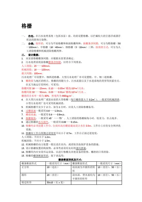
格栅一、作用:在污水处理系统(包括水泵)前,均需设置格栅,以拦截较大的呈悬浮或漂浮状态的固体污染物。
二、分类:按形状,可分为平面格栅和曲面格栅两种;按栅条净间隙,可分为粗格栅(50—100mm)、中格栅(16—40mm)、细格栅(3—10mm)三种;按清渣方式,可分为人工清除格栅和机械清除格栅两种。
三、设计数据:1.水泵前格栅栅条间隙,应根据水泵要求确定。
2.污水处理系统前格栅栅条净间隙,应符合下列要求:人工清除:25——100mm;机械清除:16——100mm;最大间隙:100mm。
污水处理厂可设置中、细两道格栅,大型污水处理厂亦可设置粗、中、细三道格栅。
3.栅渣量与地区的特点、格栅的间隙大小、污水流量以及下水道系统的类型等因素有关。
在无当地运行资料时,可采用:格栅间隙16——25mm:0.10——0.05m³栅渣/103m³污水;格栅间隙30——50mm:0.03——0.01m³栅渣/103m³污水。
、栅渣的含水率一般为80%,密度约为960kg/m³。
4.在大型污水处理厂或泵站前的大型格栅(每日栅渣量大于0.2m³),一般采用机械清渣。
小型污水处理厂也可采用机械清渣。
5.机械格栅不宜少于2台。
如为1台时,应设人工清除格栅备用。
6.过栅流速一般采用0.6——1.0m/s。
7.栅前流速,一般采用0.4——0.9m/s。
8.格栅倾角,一般采用45°——75°。
人工清除的格栅倾角小时,较省力,但占地多。
9.通过格栅的水头损失,一般采用0.08——0.15m。
10.格栅间必须设置工作台,台面应高出栅前最高设计水位0.5m。
工作台上应有安全和冲洗设施。
11.格栅间工作台两侧过道宽度不应小于0.7m。
工作台正面过道宽度:人工清除:不应小于1.2m;机械清除:不应小于1.5m。
12.机械格栅的动力装置一般宜设在室内,或采取其他保护设备的措施。
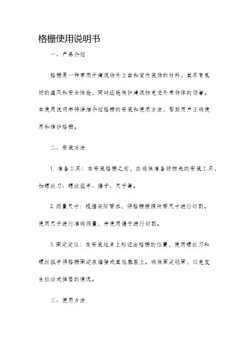
格栅使用说明书一、产品介绍格栅是一种常用于建筑物外立面和室内装饰的材料,其具有良好的通风和安全性能,同时还能保护建筑物免受外来物体的侵害。
本使用说明书将详细介绍格栅的安装和使用方法,帮助用户正确使用和维护格栅。
二、安装方法1. 准备工具:在安装格栅之前,应确保准备好相关的安装工具,如螺丝刀、螺丝扳手、锯子、尺子等。
2. 测量尺寸:根据实际需求,将格栅按照所需尺寸进行切割。
使用尺子进行准确测量,并使用锯子进行切割。
3. 固定定位:在安装地点上标记出格栅的位置,使用螺丝刀和螺丝扳手将格栅固定在墙壁或其他基座上。
确保固定稳固,以免发生松动或掉落的情况。
三、使用方法1. 保持清洁:定期清洁格栅表面,以保证其外观整洁并防止积灰或杂物对其造成堵塞。
2. 防止冲击:格栅不宜经常受到冲击或剧烈振动,以免损坏或脱落。
3. 维护润滑:格栅的移动部件,如滑轨、滑块等,需定期进行润滑保养,以确保其正常使用和延长使用寿命。
4. 防止日晒雨淋:长时间暴露在阳光雨水中会对格栅造成损害,因此需采取防水和防晒措施,如布置篷布或给格栅表面进行涂层处理。
四、注意事项1. 安全操作:在安装和使用格栅时,应注意安全操作,避免造成人员伤害或物品损坏。
2. 避免过载:格栅具有一定的承载能力,超过承载范围使用会导致安全隐患,请勿超载使用。
3. 定期检查:长时间使用后需定期检查格栅的固定件是否紧固,滑动部件是否畅通,如有松动或堵塞应及时处理。
4. 避免使用过程中猛拉或重物撞击,以免导致变形或损坏。
五、维修方法1. 松动固定件:如格栅出现松动的情况,应使用螺丝刀和螺丝扳手重新固定。
2. 滑轨滑块维护:格栅的滑轨和滑块如有卡滞或不灵活的情况,可使用润滑油进行维护,或清理滑道上的杂物。
3. 损坏更换:如格栅的部件严重损坏,无法修复时,应及时更换相应的配件,确保格栅的正常使用。
六、存储和保养1. 存放环境:格栅应存放在干燥、通风和避免阳光直射的环境中。
阶梯格栅一、主要用途阶梯式格栅除污机,是一种将拦污和除污结合于一体的高效细格栅除污设备。
适用于大、中、小型泵站作为精细格栅,拦截、清除水中的漂浮物,如:杂草、纸片、烟头、瓜子、纤维、毛发等,该机型具有很高的污物捕获率,可保证后续处理工艺的有效实施。
二、主要结构及特点阶梯式格栅除污机主要由驱动装置、机架、牵引链条、带提升阶梯的网板及电控系统等主要部件组成。
驱动电机安装在机架正向的主轴上,两侧网板在传动链条的带动下,自下而上将其长度范围内截留的污物向上提取,抵达上部时,通过链轮的转向功能,自动完成翻转卸污工作,渣水排入两侧网板之间的集渣槽后自流排出机外。
阶梯式格栅除污机的驱动装置位于机架上部。
在机架前后二侧设置了螺旋式调节装置,调整传动链条紧松。
阶梯式格栅除污机的机架为不锈钢板材与型钢组装、焊接成的一整体式长方体刚性结构。
机架下部迎水端开有一个进水洞口,机架的前后壁板上设有导轨。
机架安装于格栅井的中央,机架的两侧与格栅井之间的间隙为格栅滤后出水的通道。
在机架的迎水端两侧布置了导流挡板,其在导流的同时,可防止漂浮垃圾通过。
传动用的牵引链轮及导向装置,分别置于机架两侧的上部和下部。
阶梯式网板采用ASTM304不锈钢制造,网面为规则排列的小孔,具有过水与截污的功能,台阶面能截留较大的污物。
三、主要技术参数GSJT-900-1600-4阶梯孔径mm渠深mm格栅宽度mm阶梯式格栅除污机四、安装调试说明1、设备起吊安装前先需检查的内容1.1 检查设备在运输过程中是否损坏现象。
1.2 根据设备安装图检查基础尺寸是否符合要求。
1.3 格栅井两侧于井顶部平台面应垂直,其垂直误差不超过20mm;格栅井两侧应平行,其平行度误差不超过20mm。
1.4 检查各预埋件位置、尺寸是否与图纸一致,预埋钢板应与格栅井顶部平台平。
以上内容检查完毕符合要求,既可安装就位。
2、设备安装的具体要求本机放入基础就位后,其安装角度应符合设计要求,格栅卸料口平面应与格栅井操作平台面平行,格栅墙板应与格栅井操作平台面垂直,保证设备安装的水平度误差小于1/1000,然后再根据安装图将设备与预埋件焊成一体,再将地脚螺母拧紧。
细格栅操作规程
(一)运行前的准备
1、检查设备传动机构的紧固螺钉是否牢固,该设备四周有无障碍物。
2、控制面板指示灯都没有报警,且显示正常。
3、检查细格栅耙齿上有无缠绕,链条及齿轮传动部份是否润滑得当。
(二)开机运行
就地手动运行:
将1#格栅工作方式开关(1SA)拨在“现场”位;(1SA1)拨在“手动”位。
手动方式用于设备的维修或调试,工作时操作连续/调整按钮(1SA2)控制设备连续/点动运行。
就地自动运行:
将1#格栅工作方式开关(1SA)拨在“现场”位;(1SA1)拨在“自动”位。
设备为连续间歇运行,运行与间歇时间需通过电柜内的时间继电器(在0.5min-24h)范围内设定。
远控方式:
将1#格栅工作方式开关(1SA)拨在“远控”位。
设备的运行由
中控室发出的远控起动信号(闭合)或液位差信号(闭合)控制。
远控方式状态下,现场起动信号无效,配电柜中将“允许远控”,“运行”,“故障”信号(无源开关量)输出到控制室。
备注:1#格栅操作与2#格栅相同。
总停:
在设备运行过程中,如出现异常情况,可按动总停按钮停止设备运行。
这时总停按钮自锁。
需要恢复工作时,旋动总停按钮使之复位。
(三)注意事项
本设备应保持清洁,每天检查和清理一次,主轴承应经常润滑,用压力油枪将钙基或钙基润滑脂注入油嘴内。
粗格栅(一)操作规程1.确保电机电源线连接正确,供给电压正常。
2.观察进水沟内有无大的障碍物,如有应将障碍物清除。
3.确保链条的松紧度合适,润滑良好。
4.减速箱内润滑油油位正确,油质符合要求(润滑油为L-CKC100、L-CKC150极压工业齿轮油)。
5.点动电机,驱动整个传动机构,运转应顺畅,无异常噪音。
若运转不畅,应立即检查,排除故障。
正常运行后,此项可省略,但新装或检修后,首次运行时需严格此项规定。
6.清渣板工作是否可靠。
7.减速机通气塞应畅通。
8.粗格栅运转时,必须进行巡视。
9.手动状态下,根据栅渣量开启粗格栅。
10.自控状态下达到开启时间前,操作人员应按上述要求进行检查。
有异常情况应通知中控室。
(二)维护规程1.初运行时,每次运转,均要检测减速机温度,温度≤70℃,温升≤60℃。
若温度较稳定,可以延长至每周检测一次。
2.保持轴承、传动链条等运转处的良好润滑,每月轴承定期加注钙基润滑脂,链条加注链条脂。
3.每月:(1)设备外表清扫干净。
(2)疏通减速机顶部通气孔,确保畅通。
(3)检查一次油位,不足时添加。
5.每半年:(1)检查紧固件,防止松动。
(2)检查绝缘体电阻和电缆线损坏情况,可根据具体情况适当延长至每年一次。
6.每年必须定期对设备进行一次全面检修,对磨损严重的零件必须更换,并进行防腐处理。
7.首次运行150小时后更换齿轮箱润滑油(冬季选用L-CKC68,一般选用L-CKC100、150)热机换油,并冲洗干净,以后每隔3~6个月换油一次。
8.设备投入正常运行后,若与故障造成停机,应查明原因,排除故障后方可再次开机,不得再未作处理前强行开机,以免造成不必要的损害。
WLS型螺旋输送机1)开车前应作以下几点:1.清扫杂物,保持设备清洁和无影响设备运行的阻碍物存在。
2.确保正确的供给电压和正确地连线。
3.确保正确的润滑方式和润滑剂用量。
4.保护盖要安装正确。
5.各紧固件要正确紧固。
6.启动前,应保证没有任何人正在进行与输送机有关的工作。
移动抓斗式格栅除污机安装、维护、操作使用手册地址(ADD):****************邮编(PQ): **************电话(TEL): ***************传真(FAX):*****************电邮(E-mail):*******************YDZD型移动式格栅除污机安装使用说明书一、主要用途与适用范围YDZD型移动抓斗式格栅除污机是我公司为满足大流量、宽渠道的格栅清污需求,在原钢丝绳格栅除污机的基础上设计了可水平移动的台车机构和驱动控制的一种新机型。
设计中考虑到大型取水构筑物负荷大的特点,用大容积的耙斗来清除水中的垃圾杂物。
三条钢丝绳其中两条钢丝绳在主电机的带动下将耙斗缓慢平稳的提升至出料口位置,另一条(即位于中间)钢丝绳在差动电机的带动下将耙斗翻转,并配合刮板机构将栅渣排除,达到除污的目的。
使用时可采用一台除污机进行多组并列格栅的清污,投资少,效果好,利用率高。
三条钢丝绳通过传感器相互配合,使耙斗升降和开合自如。
移动机构在移动电机的带动下平稳在轨道上移动,预定位置有定位开关和定位销,使其能够在任意一组格栅位置准确定位。
该格栅适用于进水渠道较宽的自来水厂;雨、污水提升泵站;污水处理厂;电厂等进水口处,依次去除水体中的漂浮垃圾和杂物,保护后续工艺设备安全运行。
二、主要规格及技术参数(见下表)三、主要结构及特点1、YDZD型移动格栅除污机由下列部件组成:上机架、移动装置、升降机构、差动机构、卸料机构、耙污装置、格栅胸墙组,电控装置等。
2、YDZD型移动格栅除污机由三台相互独立的减速机带有制动电机来驱动,即,移动、升降和差动控制电机,移动减速机电机位于上机架底盘一侧,通过转动轴带动行走轮作往返运动,升降减速机位于上机架工作平台上驱动钢丝绳卷筒,使耙斗作升降动作,差动减速机装于机架顶部带动差动滑轮、滑动、使耙斗做开、闭耙动作。
3、YDZD型格栅除污机设计有独特的“抓斗式”齿耙,它由斗体及两侧装有导轨,为抓斗(齿耙)的上下提供一个运行通道,使抓斗运行平稳,并有效地抓污排污。

anddto introduced newer, better and efficient systems that addressed these needs. With an uncompromising approach towards quality and unflinching commitment to perfection, the company successfully established it’s a brand GLENSTORMS, in the segment.Application & Design:Duly powder coated extruded aluminium linear horizontal fixed bar grills, with 15 deg. deflection blade having pitch of 13 mm.Rating:Pressure Drop (∆Pg)-Velocity- 3 m/s10 mm of w.g.200 C7.3 mTemperature-Throw-Standard Construction:Dimension:1.Frame-Powder Coated Extruded Aluminium Section.Powder Coated Extruded Aluminium Section. 2.Louver-Height10051509200132501630020350234002745030No. OfBlades Frame:Louver:Size Limitations:Minimum Size- 4" (100 mm) ⬜70.9"(1800 mm) ⬜Maximum Size-All Dimensions are in mm.Model : GL 15Blade Deflection:0Model : GL 15(Noise rating)Model : GL 15Optional Features:-Available with Aluminium/steel Construction opposed blade Collar Damper with a screw driver operation system through the face of the grille.Available in black or white vertical spacers.Available louver thickness 0.6 mm, 0.8 mm, 1.0 mm & 2.0 mm from back.Model : G-HV Application & Design:All Dimensions are in mm..These grills are duly powder coated extruded aluminium double adjustable louver grills, with fronthorizontal and rear vertical.This grille controls the airstream in both the horizontal and vertical planes.It is Available in powder coated/anodised finish.Optional Features:-Model : G-HV(Noise rating)Model : G-CNV-OSF, G-CNV-BSFApplication & Design:These grills are powder coated extruded aluminium constructionwith horizontal fixed vanes normally used as a door grille.These grilles are carefully designed to suit the needs of air transferin those areas where privacy is not intended to be compromised.The construction is 100% non -vision ensures that no visibility ispossible in any condition.Model : G-CNV-OSF, G-CNV-BSF(Noise rating)Application & Design:All Dimensions are in mmThese Diffusers are duly powder coated extruded Aluminium ceiling mounted multi-slot Diffuser 2.Blade : 20 Ga, Aluminium Extrusion Section.Model : G-DSModel : G-DSNo. of Slots Air Flow (CFM)Velocity (FPM)Throw(m)Pressure Drop (in mm w.g)Noise (db)Performance TablePerformance Notes:1291201.9 5.1---59239 3.114-----88359 4.73215591202.23.51182394.414118159 3.6 6.3176359 6.632171762395.4122353197.225142352396.2142942997.822112942397.4243533599.5322535328710.7332041233512.642242345Pressure: All pressure are in mm of water.Maximum throw to a terminal velocity of 70 fpm.Throw data is based on supply air & room air being at isothermal conditions.The noise values are based on a room absoption of 10 db.Application & Design:These diffusers are powder coated extruded/stamped aluminium muti-cone ceiling diffuser withStandard Construction:1.Flange-Powder Coated Extruded Aluminium Section.Powder Coated Stamped Sheet.2.Ring-Model : G-RDC-FAvailable in powder coated-white finish.Other colour shades available on request.Optional Features:-Quick Selection:Model : G-RDC-F(Noise rating)Application & Design:Standard Construction:1.Flange-Powder Coated Extruded Aluminium Section.Model : G-RDC-GPowder Coated Stamped Sheet.2.Ring-All Dimensions are in mm.These diffusers are duly powder coated stamped aluminium multi-cone grid type ceiling diffuser with removable centre core helps to facilitate cleaning and damper adjustment.Out to out size: 595 X 595 mm neck size 450 x 450 mm.Model : G-RDC-GQuick Selection:Available in powder coated-white finish.Other colour shades available on request.Optional Features:-(Noise rating)Application & Design:Size Limitations:Minimum Size-11.81 in.(300 mm) x 11.81 in.(300 mm) 23.62 in.(600 mm) x23.62 in.( 600 mm)Maximum Size-Model : G-RDC-PNeck sizeNeck Velocity,fpm Velocity pressure,mm of wg. Total pressure, mm of wg.Total pressure, mm of wg.Total pressure, mm of wg.Flow Rate, CFMFlow Rate, CFMFlow Rate, CFMNCNCNCThrow (ft.)Throw (ft.)Throw (ft.)Performance TablePerformance Notes:200 x 2000.450.73 1.06 1.44 1.87 2.36 2.924000.255000.406007000.558000.789001.0110001.26 1.57145180205240274306340----2124292-53-64-74-85-96-96-100.75 1.14 1.65 2.23 2.92 3.70 4.57---192427322152703243804314865403-64-85-96-106-117-128-121.04 1.652.363.224.215.336.57310390465560624702780--15212431344-85-106-117-128-139-1410-15 250 x 250300 x 300Pressure: All pressure are mm of water gauge.The NC values, sound pressure level, are based on a room absorption of 10 DB & one diffuser. Blanks(-) indicates an NC level below 15Throw of air is given in feet (each side) with terminal velocities of 100 fpm & 50 fpm (maximum). Air flows is in cubic feet per minute, cfm.Model : G-SWD-F Application & Design:Fixed blade swirl diffusers presents an attractive and aerodynamically efficient alternative to conventional square ceiling terminals. These diffusers are design to produce a horizontal, radial air pattern with a turbulent, high induction jet characteristics and are ideally suited for applications with high heating or cooling differentials.It is manufactured from aluminium with press formed blades, the units can be supplied complete with a duct mounting collar for easy assembly. The steel duct mounting collar can be used as a means of fixing and supporting the diffuser from rigid duct work, or alternatively ceiling support brackets (supplied as standard) can be fitted for use with flexible ducting.Model : G-SWD-F Selection CriteriaJet throw data is expressed in meters and is based on a terminal velocity of 0.5 m/s and a 10 C cooling differential.NR levels are based on sound pressure levels with an assumed 8 dB room absorption factor. pressure loss data is shown in terms of static pressure loss (Pa) based on a diffuser fitted with aDM collar, or for a diffuser installed in a WTP plenumPerformance TableG-CDStandard Construction:1.Flange-Powder Coated Extruded Aluminium Section.Powder Coated Stamped Sheet.2.Ring-Application & Design:All Dimensions are in mm.Model : G-CD-SFModel : G-CD-SF(Noise rating)Model : G-JND Application & Design:These diffusers are powder coated aluminium rotatable jet nozzle and diffuser which allows bothAll Dimensions are in mm.Model : G-JNDPerformance Notes:(Noise rating)Application & Design:These diffusers are duly powder coated aluminium double skin eye-ball type rotable jet nozzle .This type of supply nozzles are capable of delivering air to spaces where long distance penetration and low noise levels are required. Suitable for cold and warm air supply applications, these versatile adjustable units are ideal for providing focussed ventilation or where precision is required. Where grouped penetration can be considerably enhanced.Inner Cowl-Outer Cowl-High grade Aluminum spinning High grade Aluminum spinning Standard(a) Epoxy polyester powder coated of white/pure white.(b) Natural Anodized.Finish-Standard Construction:Model : G-JNSize Limitations:Minimum Size- 4 in.(100 mm) dia. 16 in.(400 mm) dia.Maximum Size-Flow G-JNRate ThrowPressureNoiseLossSize cfm m Pa dBA100271035<20 55207527 803015042125361012<20 421123<20 72205020 105301503716048108<20 301320<20 6320 5224 148301003220063105<20 1051718<20 70203321 14830802525080107<20 1611814<20 224203021 31730702331510110<5<20 2072010<20 31730282040013510<5<202731208<203172415<204133030<20Model : G-JNModel : G-SD Application & Design:ODOGModel : G-SD******************* +91 9911214199, 8585919596。
GSM610微滤机(外进水转鼓式细格栅)使用说明书***********有限公司2020 年 5 月目录1.前言2.主要结构及工作原理3.主要技术参数4. 设备安装及调试5. 常见工作故障及排除方法6. 操作与保养1.前言1).简介:GSM型微滤机(外进水转鼓式细格栅)是一种能连续而有效地筛除水中固体悬浮物的设备。
主要应用于污水的预处理或工业过筛工艺中。
在某些污水处理中,经过筛滤的污水可去除30%至60%的有机或无机悬浮固体,大幅度降低后道工序的处理负荷。
2).优点:1)设备价格低,但能大幅度降低废水系统的处理负荷;2)工作稳定可靠,维修费用少;3)楔形鼓面尤其适合流体通过,不易发生堵塞;4)整机采用优质不锈钢制造,永不腐蚀;5)可用于高温高浓度液体的筛选过滤;6)能够自动连续运转,自动排渣和清洗堵塞污物;7)采用鼓形设计,过滤面积大,因此在相同的处理量时,结构紧凑,占地面积小,耗能少;8)全封闭设计,防止可能的二次污染。
2.主要结构及工作原理:本机由转鼓,驱动机构,清洗系统,卸料机构,密封组件,检查门组件,机架等组成。
工作原理:污水(或其它原水)从转鼓鼓面的前部穿过鼓面流入转鼓,并从下部流出,污水中的悬浮物滞留在转动的鼓面上。
被截留的污物随着鼓面的转动,由进水端送到另一侧的卸料端,并由卸料机构将其铲下。
3. 主要技术参数1).电机功率:0.55KW (380V,50Hz);防护等级:IP55;2).转鼓直径:616mm;3).转鼓长度:610mm;4).鼓面栅隙:1.0mm;5).转鼓转速:17r/min;6).进水管直径DN100, 出水管直径DN150, 且均为松套法兰。
清洗水管直径DN20;7). 清洗水压强:3bar;流量:3.9L/min;8). 处理量: 800m /d (清水的过滤量);9). 外形尺寸(L×W×H):1300×1400×1600;10). 安装尺寸:995×806。
格栅除污机使用说明一、产品概述二、使用前准备1.确保格栅除污机的各个部件完好无损,无松动现象。
2.确保电源供应稳定,地线连接可靠。
3.检查格栅清洗机具备所需的清洗剂和工具。
三、操作步骤1. 将格栅除污机放置在离格栅边缘50cm的距离处,并确保安全锁住。
2.打开电源开关,格栅除污机即进入待机状态。
3.打开进料阀,待进料管道内有一定压力后,缓慢打开出料阀,将污水通入格栅。
4.将清洗剂按照所需比例倒入清洗剂箱中,并打开清洗剂泵电源开关。
5.根据实际情况,选择合适的清洗剂浓度和清洗时间,调整清洗剂浓度调节器和清洗时间调节器。
6.打开清洗剂泵电源开关,使清洗剂从泵中流出,通过喷洒管喷洒到目标区域。
7.根据清洗区域进行对应的工作,例如使用刷子进行刷洗、使用水枪进行冲洗等。
8.清洗结束后,关闭清洗剂泵电源开关,并将喷洒管倒至底部排出清洗剂残留。
9.关闭进料阀和出料阀,将格栅除污机从原位移到下一个工作区域。
四、注意事项1.在使用格栅除污机前,务必熟悉并遵守相关安全操作规程。
2.在操作过程中,必须正确佩戴防护装备,如手套、护目镜等,以免造成伤害。
4.清洗剂浓度的调整应慎重进行,避免使用过量或过低的浓度。
5.清洗剂泵电源开关在清洗结束后应及时关闭,避免长时间工作造成设备损坏。
6.在进行清洗作业时,应注意不要将清洗剂喷溅到周围设备或人员上。
7.清洗结束后,及时将喷洒管内的清洗剂倒掉,并进行清洗和消毒。
8.格栅除污机的移动过程中,应谨慎操作,确保不会碰到其他设备或造成任何损坏。
五、维护保养1.格栅除污机在使用后应进行清洗,去除污垢和残留的清洗剂。
2.定期检查和更换清洗剂泵、喷洒管等易损件,确保其正常工作。
3.定期清理格栅除污机的进料管道和出料管道,防止堵塞发生。
4.格栅除污机长时间不用时,应进行防尘工作,避免灰尘、水汽等物质进入内部。
六、故障排除1.若格栅除污机不能正常启动,首先检查电源是否正常连接,排除电源问题。
2.若格栅清洗效果不理想,可适当增加清洗剂浓度或清洗时间。
回转式粗格栅除污机操作规程宜兴市华电环保设备有限公司目录1、概述:2、性能参数:3、设备技术性能和结构特点:4、主要零部件材质5、控制系统6、设备制造标准7、设备测试:8、主要技术参数控制9、设备外观检测10、检验与试验要求10.1、试验要求:10.2、检验:11、设备的安装、运行、维修手册11.1、安装与操作11.2、注意事项及维护1、概述:我公司提供的回转式机械格栅为成套设备。
主要用于城镇污水处理厂、住宅小区预处理装置、市政污水管道、自来水厂和电厂冷却水等进水口处进行杂物分离的设备,还可用于纺织、水果、水产、造纸、酿酒、屠宰、制革等行业的生产工艺中进行水洗或预处理筛分,是种理想的固液筛分设备。
回转式格栅除污机由驱动机构驱动主轴旋转,主轴两侧的链轮使牵引链条作回转运动,在环形链条上均布齿耙,齿耙间距与格栅栅距交错并列。
回转运动时移动齿耙插入固定栅条间隙中上行,将格栅截留下的悬浮物(栅渣)刮至平台上端的卸料处,并由卸污机构将栅渣卸至输送机或贮渣车内。
2、性能参数:设备名称回转式粗格栅除污机设备型号SGL-800数量1台排渣高度1000mm渠道宽度900mm格栅宽度800mm渠道深度6650mm栅距20mm安装角度70°电机功率 1.5KW减速机SEW电源、防护及绝缘等级50HZ 3相 380V IP55 F级工作方式间歇或连续运行3、设备技术性能和结构特点:A、格栅采用间距相等的直线形栅条,以倾斜方式安装,安装角度为70°,并在栅前采用循环链条牵引的前置式耙污机构进行除污。
B、格栅能根据时间或栅前后水位差启动,能满足截留和耙除水中较大颗粒的垃圾等杂物。
C、格栅在达到设计流量的情况下能24小时连续运行,同时也能间断运行和长时间停机后正常启动运行。
D、耙污机构在运行中断后一旦恢复运行时,耙污机构能在完全阻塞的格栅上去除积聚的栅渣。
E、格栅架、支架及各运动构件均为户外型,所有构件的设计保证在最恶劣的环境中使用寿命最长。
格栅使用说明书
一、产品简介
格栅是一种常见的建筑材料,通常由金属或塑料制成。
它们被
广泛应用于建筑物的外部墙壁、阳台、窗口等处,不仅起到装饰作用,还能有效阻挡杂物进入建筑内部,提供安全保护。
本说明书将
介绍格栅的安装、使用和维护等方面的知识,帮助用户正确使用和
管理格栅。
二、安装步骤
1. 准备工作:
在安装格栅之前,需要对墙面进行清理,确保墙面干燥、平整,并清除多余的灰尘和杂物。
2. 安装位置:
根据需要,选择合适的位置安装格栅。
通常,格栅被安装在楼
层或阳台的窗户上,以提供通风和安全保护。
3. 格栅定位:
根据实际需要,确认格栅的尺寸和位置,并使用铅笔标记出孔位,以便后续安装。
4. 预钻孔:
使用电钻和钻头,在标记的孔位上预先钻孔。
确保孔位的深度和直径与螺丝相匹配,以便后续的螺丝安装。
5. 安装格栅:
将格栅放置在预先钻好孔位的位置上,用螺丝固定格栅。
确保格栅安装牢固,不松动。
6. 清洁和润滑:
安装完成后,用清洁剂和软布擦拭格栅,以保持其外观整洁。
定期涂抹机油或润滑油,以确保格栅在开启和关闭过程中能够顺畅运行。
三、使用注意事项
1. 防止儿童靠近:。
提篮格栅安装使用维护说明书提篮式格栅是一种自动提篮格栅污水过滤装置,包括导轨、提篮格栅、下限位杆、临时格栅和提升电机,提篮格栅固定在导轨上并能沿导轨滑动,提升电机固定在导轨并与提篮格栅通过缆绳连接,下限位杆和临时格栅活动连接在导轨下部并通过连接索连接,提篮格栅将下限位杆压在导轨下方。
本发明通过导轨、提篮格栅、提升电机和临时格栅的相互配合做到了对水体的自动不间断过滤,提高了取水的水质,节省了人力物力,弥补了水体过滤中的过滤格栅易堵塞的缺陷首先,要看设计小时流量,设计小时流量确定后,准备选用的格栅厂家的样本有对应的流量,选相近的即可。
确定了格栅的型号,格栅的尺寸也就确定了,据此,设计格栅井即可。
格栅井是废水处理个常俐的构筑物之一,其主要部分为格栅除污机。
格栅的主要作用是保护水泵和防止管道堵塞,格栅通道截污的同时也削减了污染物负荷。
水是宝贵的资源,水资源的日益短缺和社会经济的不断发展使得水资源的利用显得愈发重要。
为了进行下一步的污水处理工作,我们需要先将污水中的漂浮物,砂石颗粒,枯枝烂叶等肉眼可见的污染物过滤剔除出去,需要一种方便的污水过滤处理设备。
通常使用一个固定栅栏过滤,由于栅栏固定,杂物清理很不方便。
如果无法在固定时间内清理,杂物有可能在管道内淤积阻塞管道。
污水进水管道口往往安置在地下的位置,拆装、更换固定栅栏很不方便,清理管道内杂物也很不方便。
当采用手动提篮提升时,在提升格栅时管道口没有过滤栅栏,污水直接流入管道会影响水质,导致下一道工序无法进行对污水处理设备造成影响。
对于小型污水厂而言,由于缺少操作人员,很难保证定时定量的完成对提篮的清理。
提篮格栅优点:1、节省材料:承受相同荷载条件下省材料的方式,相应地,可减少支承结构的材料。
2、减少投资:省材料,省人工,省工期,免清洁和维护。
3、施工简便:在预安装好的支承上用螺栓夹国定或焊接固定,一人即可完成。
4、节省工期:产品无需现场再加工,安装非常迅速。
BOG RM Rotary Drum GrilleBOG RM 转鼓格栅机是一种在传统旋转格栅技术上革新部分原理的机械过滤方法。
它适用于把液体中存在的较大悬浮物质(如纺织印染、农业养殖、沼液垃圾、纸浆纤维等)最大限度地分离出来,实现固、液分离的目的。
BOG-RM 转鼓格栅机与其它过滤方法的区别在于过滤介质空隙小,借助筛网回转的离心力,在较低的水利阻力下,高效率分离截留住悬浮杂质。
这种新型的水处理设备,主要去除废水中的纤维状物质,设备全密封高效循环重复使用,节约污水处理成本设备广泛适用于需进行固液分享的各种场合,如渗滤液、造纸、纺织印染、化工污水、城市生活污水、农业养殖等。
尤其适用于纺织印染、造纸白水的处理。
BOG RM Rotary drum grille is a new kind of mechanical filter, which is widely used to sepatate micron rating suspended substances from liquid, for example sweage treatment of textile, printing and dyeing, agricultur-al breeding, biogas slurry, pulp fibre separation and etc.BOG-RM Rotary drum grille with very small gap of filter medium, which can intercepts suspended solids with the help of grille centrifugal force to keep a high flow velocity under low hydraulic resistance.As one of new water treatment equipments, Rotary drum grille is mainly used to remove fibers from waste water, such as sewage treatment in municipal, leachate, papermaking, textile, printing and dyeing, chemical industries and agricultural breeding etc. It has a excellent performance in sweage treatment of textile, print-ing and dyeing, and papermaking plant of white water filtration, close cycle of water reuse achieves greatsaving of cost in sewage treatment.01设备结构简单高效,运行平稳,维修方便,使用寿命长。
回转式粗格栅除污机操作规程宜兴市华电环保设备有限公司目录1、概述:2、性能参数:3、设备技术性能和结构特点:4、主要零部件材质5、控制系统6、设备制造标准7、设备测试:8、主要技术参数控制9、设备外观检测10、检验与试验要求10.1、试验要求:10.2、检验:11、设备的安装、运行、维修手册11.1、安装与操作11.2、注意事项及维护1、概述:我公司提供的回转式机械格栅为成套设备。
主要用于城镇污水处理厂、住宅小区预处理装置、市政污水管道、自来水厂和电厂冷却水等进水口处进行杂物分离的设备,还可用于纺织、水果、水产、造纸、酿酒、屠宰、制革等行业的生产工艺中进行水洗或预处理筛分,是种理想的固液筛分设备。
回转式格栅除污机由驱动机构驱动主轴旋转,主轴两侧的链轮使牵引链条作回转运动,在环形链条上均布齿耙,齿耙间距与格栅栅距交错并列。
回转运动时移动齿耙插入固定栅条间隙中上行,将格栅截留下的悬浮物(栅渣)刮至平台上端的卸料处,并由卸污机构将栅渣卸至输送机或贮渣车内。
2、性能参数:设备名称回转式粗格栅除污机设备型号SGL-800数量1台排渣高度1000mm渠道宽度900mm格栅宽度800mm渠道深度6650mm栅距20mm安装角度70°电机功率 1.5KW减速机SEW电源、防护及绝缘等级50HZ 3相 380V IP55 F级工作方式间歇或连续运行3、设备技术性能和结构特点:A、格栅采用间距相等的直线形栅条,以倾斜方式安装,安装角度为70°,并在栅前采用循环链条牵引的前置式耙污机构进行除污。
B、格栅能根据时间或栅前后水位差启动,能满足截留和耙除水中较大颗粒的垃圾等杂物。
C、格栅在达到设计流量的情况下能24小时连续运行,同时也能间断运行和长时间停机后正常启动运行。
D、耙污机构在运行中断后一旦恢复运行时,耙污机构能在完全阻塞的格栅上去除积聚的栅渣。
E、格栅架、支架及各运动构件均为户外型,所有构件的设计保证在最恶劣的环境中使用寿命最长。
09(173)GL600 回转式格栅除污机使用说明书09(173)GL600 SM无锡市通用机械厂有限公司二OO九年六月无锡市通用机械厂有限公司09(173)GL600 回转格栅除污机使用说明书09(173)GL600SM共7页第1页目录一、主要用途与适用范围⋯⋯⋯⋯⋯⋯⋯⋯⋯⋯⋯⋯⋯⋯⋯2二、主要规格及技术参数⋯⋯⋯⋯⋯⋯⋯⋯⋯⋯⋯⋯⋯⋯⋯2三、工作原理⋯⋯⋯⋯⋯⋯⋯⋯⋯⋯⋯⋯⋯⋯⋯⋯⋯⋯⋯⋯2四、主要结构及特点⋯⋯⋯⋯⋯⋯⋯⋯⋯⋯⋯⋯⋯⋯⋯⋯⋯2五、维修及保养⋯⋯⋯⋯⋯⋯⋯⋯⋯⋯⋯⋯⋯⋯⋯⋯⋯⋯⋯3六、设备安装说明⋯⋯⋯⋯⋯⋯⋯⋯⋯⋯⋯⋯⋯⋯⋯⋯⋯⋯4七、外形图⋯⋯⋯⋯⋯⋯⋯⋯⋯⋯⋯⋯⋯⋯⋯⋯⋯⋯⋯⋯⋯4八、电气原理图⋯⋯⋯⋯⋯⋯⋯⋯⋯⋯⋯⋯⋯⋯⋯⋯⋯⋯⋯4九、电气互连图⋯⋯⋯⋯⋯⋯⋯⋯⋯⋯⋯⋯⋯⋯⋯⋯⋯⋯⋯4描表描校签字资料来源编制日期校对标准化提出部门审定标记处数更改文件号签字日期批准文号批准描表描校签字一、主要用途与适用范围回转格栅除污机主要用途为固液筛分,适用于市政污水处理厂预处理工艺,如市政污水处理厂和住宅小区污水处理设施以及市镇渠道的进水口处,也可以用于自来水厂和电厂冷却水进口处进行杂物分离保护水泵叶轮,减轻后续工序的处理负荷,是一种国内先进的固液筛分设备。
二、主要规格及技术参数产品型号:GL600机架宽度:600mm栅条间距:20mm安装角度:75°电机功率: 1.1kW三、工作原理本设备由驱动装置、机架、耙栅系统、导向装置及电气控制系统等组成。
驱动装置采用摆线针轮减速机,结构紧凑,调整维修方便。
耙齿系统由一组独特的耙齿、套筒滚子链及栅体组成。
耙齿与特制套筒滚子链装配后在减速机驱动下围绕栅体作回转运动。
被栅体截留的杂物随耙齿的向上运动而与液体分离,然后耙齿沿滑槽板继续上升,当耙齿运行到设备上部经导向装置后反转,杂物在滑槽板上由耙齿推动继续向前,然后靠自重下落到卸料板上。