曲柄滑块机构运动分析
- 格式:docx
- 大小:49.14 KB
- 文档页数:5
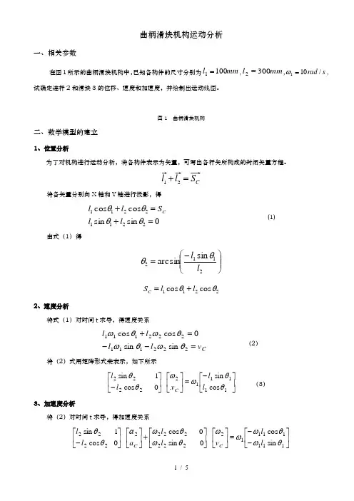
曲柄滑块机构运动分析一、相关参数在图1所示的曲柄滑块机构中,已知各构件的尺寸分别为mm l 1001=,mm l 3002=,s rad /101=ω,试确定连杆2和滑块3的位移、速度和加速度,并绘制出运动线图。
图1 曲柄滑块机构二、数学模型的建立1、位置分析为了对机构进行运动分析,将各构件表示为矢量,可写出各杆矢所构成的封闭矢量方程。
C S l l =+21将各矢量分别向X 轴和Y 轴进行投影,得sin sin cos cos 22112211=+=+θθθθl l S l l C(1)由式(1)得 ⎪⎪⎭⎫ ⎝⎛-=2112sin arcsin l l θθ 2211cos cos θθl l S C +=2、速度分析将式(1)对时间t 求导,得速度关系C v l l l l =--=+222111222111sin sin 0cos cos θωθωθωθω (2)将(2)式用矩阵形式来表示,如下所示 ⎥⎦⎤⎢⎣⎡-=⎥⎦⎤⎢⎣⎡⎥⎦⎤⎢⎣⎡-1111122222cos sin . 0 cos 1 sin θθωωθθl l v l l C (3) 3、加速度分析将(2)对时间t 求导,得加速度关系⎥⎦⎤⎢⎣⎡--=⎥⎦⎤⎢⎣⎡⎥⎦⎤⎢⎣⎡+⎥⎦⎤⎢⎣⎡⎥⎦⎤⎢⎣⎡-1111111222222222222sin cos 0 sin 0 cos 0 cos 1 sin θωθωωωθωθωαθθl l v l l a l l C C三、计算程序1、主程序%1.输入已知数据clear;l1=0.1;l2=0.3;e=0;hd=pi/180;du=180/pi;omega1=10;alpha1=0;%2.曲柄滑块机构运动计算for n1=1:721theta1(n1)=(n1-1)*hd;%调用函数slider_crank计算曲柄滑块机构位移、速度、加速度[theta2(n1),s3(n1),omega2(n1),v3(n1),alpha2(n1),a3(n1)]=slider_crank(theta1(n1),omega1,alp ha1,l1,l2,e);endfigure(1);n1=0:720;subplot(2,3,1)plot(n1,theta2*du);title('连杆转角位移线图');xlabel('曲柄转角\theta_1/\circ');ylabel('连杆角位移/\circ');grid onsubplot(2,3,2)plot(n1,omega2);title('连杆角速度运动线图');xlabel('曲柄转角\theta_1/\circ');ylabel('连杆角速度/rad\cdots^{-1}');grid onsubplot(2,3,3)plot(n1,alpha2);title('连杆角加速度运动线图');xlabel('曲柄转角\theta_1/\circ');ylabel('连杆角加速度/rad\cdots^{-2}');grid onsubplot(2,3,4)plot(n1,s3);title('滑块位移线图');xlabel('曲柄转角\theta_1/\circ');ylabel('滑块位移/\m');grid onsubplot(2,3,5)plot(n1,v3);title('滑块速度运动线图');xlabel('曲柄转角\theta_1/\circ');ylabel('滑块速度/m\cdots^{-1}');grid onsubplot(2,3,6)plot(n1,a3);title('滑块加速度运动线图');xlabel('曲柄转角\theta_1/\circ');ylabel('滑块加速度/m\cdots^{-2}');grid on2、子程序function[theta2,s3,omega2,v3,alpha2,a3]=slider_crank(theta1,omega1,alpha1,l1,l2,e);%计算连杆2的角位移和滑块3的线位移s3=l1*cos(theta1)+l2*cos(theta2);theta2=asin((e-l1*sin(theta1))/l2);%计算连杆2的角速度和滑块3的线速度A=[l2*sin(theta2),1;-l2*cos(theta2),0];B=[-l1*sin(theta1);l1*cos(theta1)];omega=A\(omega1*B);omega2=omega(1);v3=omega(2);%计算连杆2的角加速度和滑块3的线加速度At=[omega2*l2*cos(theta2),0;omega2*l2*sin(theta2),0];Bt=[-omega1*l1*cos(theta1);-omega1*l1*sin(theta1)];alpha=A\(-At*omega+alpha1*B+omega1*Bt);alpha2=alpha(1);a3=alpha(2);四、程序运行结果与分析图2 运动规律曲线图从仿真曲线可以看出,当曲柄以w1=10rad/s匀速转动时,连杆的转角位移变化X围大约在-20~20度之间,在90°或270°有极值,呈反正弦变化趋势;连杆的角速度变化X围大约在-3.3~3.3rad/s,在0°或180°有极值,成反余弦变化趋势;连杆角加速度变化X围大约在-35~35rad/s2,在90°或270°有极值,呈正弦变化趋势。
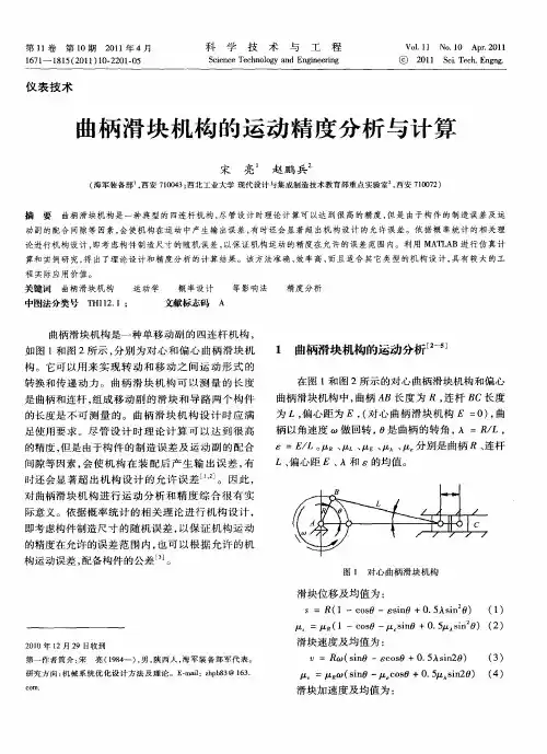
曲柄滑块机构的运动精度分析与计算宋亮;赵鹏兵【摘要】曲柄滑块机构是一种典型的四连杆机构,尽管设计时理论计算可以达到很高的精度,但是由于构件的制造误差及运动副的配合间隙等因素,会使机构在运动中产生输出误差,有时还会显著超出机构设计的允许误差.依据概率统计的相关理论进行机构设计,即考虑构件制造尺寸的随机误差,以保证机构运动的精度在允许的误差范围内.利用MATLAB进行仿真计算和实例研究,得出了理论设计和精度分析的计算结果.该方法准确、效率高、而且适合其它类型的机构设计,具有较大的工程实际应用价值.%Slider-crank mechanism is a typical four-bar linkage, in spite of the high precision when it' s calculated theoretically. The manufacturing error and kinematic pair clearance of the components will lead to the output error during the motion of the mechanism. Sometimes,it will significantly exceed the tolerance of the design. According to the probability and statistics theory, the mechanism is designed, that' s considering the random error of the component to make sure that the motion accuracy is in the allowed error range. Utilizing MATLAB to simulate and calculate based on case studies. and the theoretical design and accuracy analysis are obtained. This method is accurate and very efficiently, it also can be used in other kind of mechanism design, and it has much more practical value in engineering.【期刊名称】《科学技术与工程》【年(卷),期】2011(011)010【总页数】5页(P2201-2205)【关键词】曲柄滑块机构;运动学;概率设计;等影响法;精度分析【作者】宋亮;赵鹏兵【作者单位】海军装备部,西安,710043;西北工业大学现代设计与集成制造技术教育部重点实验室,西安,710072【正文语种】中文【中图分类】TH112.1曲柄滑块机构是一种单移动副的四连杆机构,如图1和图2所示,分别为对心和偏心曲柄滑块机构。
目录1 引言1.1 选题的依据及意义·························································································(1)1.2 国内外研究概况及发展趋势··········································································(2)1.3 论文主要工作·······························································································(3)2 曲柄(导杆)滑块机构简介····································································(4)3 曲柄(导杆)滑块机构的运动学分析3.1 曲柄导杆滑块机构的运动分析······································································(5)3.1.1 机构装配的条件····················································································(6)3.1.2 建立数学模型·························································································(6)3.1.3 计算机辅助分析及其程序设计······························································(9)3. 2曲柄滑块机构的运动分析3.2.1 机构装配的条件·····················································································(25)3.2.2 建立数学模型·······················································································(25)3.2.3 计算机辅助分析及其程序设计·····························································(27)4 曲柄(导杆)滑块机构实验台装置设计4. 1 实验台结构·································································································(40)4.2 实验台硬件操作说明···················································································(41)4.3 用SolidWorks 2006实现实验台的立体图形················································(42)总结·········································································································(46)参考文献·········································································································(47)致谢·········································································································(48)1 引言1.1 选题的依据及意义1.曲柄(导杆)滑块机构定义曲柄滑块机构是铰链四杆机构的演化形式,由若干刚性构件用低副(回转副、移动副)联接而成的一种机构。


曲柄滑块机构的运动分析及应用精编W O R D版IBM system office room 【A0816H-A0912AAAHH-GX8Q8-GNTHHJ8】机械原理课程机构设计实验报告题目:曲柄滑块机构的运动分析及应用小组成员与学号:刘泽陆(11071182)陈柯宇 (11071177)熊宇飞(11071174)张保开 (11071183)班级: 1107172013年6月10日摘要 (3)曲柄滑块机构简介 (4)曲柄滑块机构定义 (4)曲柄滑块机构的特性及应用 (4)曲柄滑块机构的分类 (8)偏心轮机构简介 (9)曲柄滑块的动力学特性 (10)曲柄滑块的运动学特性 (11)曲柄滑块机构运行中的振动与平衡 (14)参考文献 (15)组员分工 (15)摘要本文着重介绍了曲柄滑块机构的结构,分类,用途,并进行了曲柄滑块机构的动力学和运动学分析,曲柄滑块机构的运动学特性分析,得出了机构压力表达式,曲柄滑块机构的运动特性分析,得出了滑块的位移、速度和加速度的运动表达式。
最后,对曲柄滑块机构运动中振动、平衡稳定性等进行了总结。
关键字:曲柄滑块动力与运动分析振动与平稳性ABSTRACTThe paper describes the composition of planar linkage, focusing on the structure, classification, use of a slider-crank mechanism and making the dynamic and kinematic analysis, kinematics characteristics of the crank slider mechanism analysis for a slider-crank mechanism, on one hand , we obtain the drive pressure of the slider-crank mechanism ,on the other hand,we obtain the expression of displacement, velocity and acceleration of movement. Finally, the movement of the vibration and balance stability of the crank slider mechanism are summarized.曲柄滑块机构简介曲柄滑块机构定义曲柄滑块机构是铰链四杆机构的演化形式,由若干刚性构件用低副(回转副、移动副)联接而成的一种机构。

研究生课程论文科目:是否进修生?是□ 否■偏置曲柄滑块机构的运动学分析摘要:综合利用函数法和矢量法,在ADAMS软件中对偏置式曲柄滑块机构进行了仿真和运动分析。
首先,通过函数法对偏置式曲柄滑块机构的运动特性进行分析,根据矢量法建立机构的运动学矩阵方程。
然后,介绍了ADAMS在偏置曲柄滑块机构运动学及动力学分析中的应用。
通过对偏置曲柄滑块进行仿真和分析,得到其运动曲线。
该方法的仿真形象直观,测量方便,在机械系统运动学特性分析中具有一定的应用价值。
关键词:偏置曲柄滑块;ADAMS;仿真;运动学Abstract: The article analyzes the simulation and kinetic characteristic of deflection slider-crank mechanism by the function and the vector method in ADAMS.The kinematic equation of the deflection slider-crank mechanism is established by vector method. The application of ADAMS in kinematics analysis of slider-crank mechanism is presented. The motion and dynamic curves of offset slider-crank by ADAMS/View is obtained. In the method, simulation is authentic, visualized and convenient in measurement. The result shows that the method is efficient and useful in the kinematic characteristics analysis of mechanism.Keyword: offset slider-crank mechanism ; ADAMS; simulation ; kinematic0.引言平面连杆机构是由若干个构件用低副(转动副、移动副)连接组成的平而机构,它不仅在众多工农业机械和工程机械中得到广泛应用,还应用于人造卫星太阳能板的展开机构、机械手的传动机构等。

机械原理课程机构设计实验报告题目:曲柄滑块机构的运动分析及应用小组成员与学号:刘泽陆(********)陈柯宇(11071177)熊宇飞(11071174)张保开(11071183)班级:1107172013年6月10日摘要 (3)曲柄滑块机构简介 (4)曲柄滑块机构定义 (4)曲柄滑块机构的特性及应用 (4)曲柄滑块机构的分类 (8)偏心轮机构简介 (9)曲柄滑块的动力学特性 (10)曲柄滑块的运动学特性 (11)曲柄滑块机构运行中的振动与平衡 (14)参考文献 (15)组员分工 (15)摘要本文着重介绍了曲柄滑块机构的结构,分类,用途,并进行了曲柄滑块机构的动力学和运动学分析,曲柄滑块机构的运动学特性分析,得出了机构压力表达式,曲柄滑块机构的运动特性分析,得出了滑块的位移、速度和加速度的运动表达式。
最后,对曲柄滑块机构运动中振动、平衡稳定性等进行了总结。
关键字:曲柄滑块动力与运动分析振动与平稳性ABSTRACTThe paper describes the composition of planar linkage, focusing on the structure, classification, use of a slider-crank mechanism and making the dynamic and kinematic analysis, kinematics characteristics of the crank slider mechanism analysis for a slider-crank mechanism, on one hand , we obtain the drive pressure of the slider-crank mechanism ,on the other hand,we obtain the expression of displacement, velocity and acceleration of movement. Finally, the movement of the vibration and balance stability of the crank slider mechanism are summarized.曲柄滑块机构简介曲柄滑块机构定义曲柄滑块机构是铰链四杆机构的演化形式,由若干刚性构件用低副(回转副、移动副)联接而成的一种机构。
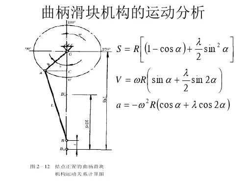
曲柄滑块机构运动分析的简便图解法曲柄滑块机构是一种具有复杂运动特性的机械系统,它在许多机械系统中起着重要的作用,能够提供有效的运动和力学参数。
因此,对曲柄滑块机构的正确分析和计算尤为重要。
近年来,研究人员们不断提出了各种新的方法来分析曲柄滑块机构的运动特性,如矩阵方法、积分方法等。
但是,这些方法都比较复杂,容易出错。
鉴于此,为了更简单地分析曲柄滑块机构的运动特性,本文提出了一种基于简单图解法的曲柄滑块机构运动分析方法。
首先,简单图解法用图形化的方式表示曲柄滑块机构的工作原理,可以清楚地展示曲柄滑块机构的运动特性,从而更容易理解它的工作原理及特性。
其次,在基于简单图解法的曲柄滑块机构运动分析中,需要考虑曲柄与滑块的结构参数,即弹性参数、刚度参数以及惯性参数等,以及滑块动力学输入信号,如外加载荷、内力和外力等。
根据这些参数和动力学信号,我们可以通过图解法求解曲柄滑块机构的运动特性,从而计算曲柄滑块的运动参数,如瞬时位置、速度、加速度等。
此外,基于简单图解法的曲柄滑块机构运动分析具有一定的普适性,可以用于分析各种类型的曲柄滑块机构,如拉伸曲柄滑块机构、蜗杆曲柄滑块机构、压簧曲柄滑块机构等。
因此,本文提出的基于简单图解法的曲柄滑块机构运动分析方法,对于分析各种曲柄滑块机构的运动特性具有重要的意义。
本文证明了简单图解法可以有效地分析曲柄滑块机构的运动特性,从而计算曲柄滑块机构的运动参数。
本文给出的分析过程,可以用来计算各种类型的曲柄滑块机构的运动特性,从而帮助工程师设计和优化曲柄滑块机构。
综上所述,本文提出的简单图解法分析曲柄滑块机构的运动特性是一种有效的方法,可以帮助工程师正确计算曲柄滑块机构的运动参数,从而更好地提高机械设备的工作效率和性能。
通过对简单图解法分析曲柄滑块机构运动特性的研究,可以为未来对曲柄滑块机构运动分析方法的设计和优化提供重要的参考和借鉴。
总之,简单图解法可以有效地分析曲柄滑块机构的运动特性和运动参数,是机械分析中非常有用的一种方法,有助于提高机械设备的性能和效率。
曲柄滑块机构运动分析的简便图解法曲柄滑块机构是利用多轴关节间通过曲柄滑块机构建立位置联系,实现传动的一类机构。
它包括曲柄轴、滑块和接头、从而实现曲线运动、往复运动、轮廓曲线运动等。
本文主要介绍一种简便的图解法,可用于分析曲柄滑块机构的运动规律。
首先是基本要素的分析,曲柄滑块机构的基本要素有曲柄轴、滑块、接头。
曲柄轴是一种用于变换位置信息的轴,它能够把位置信息传递到滑块上,使滑块形成对应的位置。
滑块能够和曲柄轴之间建立有限的接触,从而使曲柄轴把位置信息传送给接头,形成所需的运动。
其次是图解法的原理及步骤。
曲柄滑块机构的根本是控制曲柄轴运动,它的运动规律是由曲柄轴的运动控制的,而曲柄轴的运动规律是由曲柄滑块机构的特征决定的。
采用图解法可以较容易地描述出曲柄滑块机构的运动规律,从而更好地分析机构的运动特性。
图解法的基本步骤是:第一步,先确定曲柄滑块机构的结构形式,并在平面图中绘制出一个曲柄滑块机构;第二步,在机构结构图中标注它各铰接节点的位置(如轴中心点、滑块中心点等);第三步,当曲柄轴的角度发生变化时,按照基于运动的结构的原理,推算出曲柄滑块机构各连接节点的运动情况,用椭圆形表示滑块的运动轨迹;第四步,根据所得的滑块的运动轨迹的轮廓,进行有关的计算分析,可以得出某些变量与角度的规律,用于描述曲柄滑块机构的运动规律。
综上所述,图解法不仅可以帮助人们更好地理解曲柄滑块机构的运动规律,而且可以有效地解决机构设计问题。
通过图解法可以快速、准确地推导出机构的各种运动要求,从而为曲柄滑块机构的设计提供可靠的理论依据。
结论:图解法是一种利用机构特性计算分析曲柄滑块机构运动规律的简便方法,它既可以提供有效的分析手段,又可以帮助机构设计人员更好地理解机构的运动。
图解法不仅复杂性较小且易于实施,而且其结果可以用于机构的设计和调试。
曲柄滑块机构运动分析的简便图解法曲柄滑块机构是由曲柄、滑块、连接杆和钢杆等部件组成的动力学机构,它在工业上广泛应用于汽车、火车、舰船、压电等领域。
曲柄滑块机构的运动分析对汽车,火车等交通工具的运行安全,以及机械制造、检测等技术的发展具有重要意义。
这里,将介绍一种简单而有效的图解法来分析曲柄滑块机构的运动。
首先,我们需要进行示意图的绘制,这里添加了所有重要的装配元件,包括滑块、连接杆和钢杆等,还有两个表示运动轨迹的圆圈。
其次,我们可以基于这个图示,使用数学公式来分析曲柄滑块机构的运动。
一般情况下,滑块的运动轨迹是一个椭圆形,有关椭圆形轨迹的数学描述如下:$$x^2/a^2+y^2/b^2=1$$这里,a和b是椭圆形的两个顶点,这两个顶点表示滑块的最大水平和最大竖直距离。
当给定滑块的运动轨迹的长短半轴时,利用上述方程可以求出滑块的具体位置。
第三,需要计算曲柄滑块机构的速度和加速度。
通过观察图示,可以看出滑块运动圆心角θ的变化,引入θ的偏微分即可求出滑块的速度:$$V=frac {dtheta}{dt}$$而加速度可以用偏微分的第二次求得:$$A=frac {d^2theta}{dt^2}$$最后,可以利用斯特拉汀佐夫公式计算曲柄滑块机构的动偶比。
斯特拉汀佐夫公式是一个关于曲柄滑块机构的复杂的统计公式,它把滑块的输入力和转动角度等变量都连接起来,可以求出机构的总动偶比:$$I_{tot}=sum^n_{i=1}I_icdot K_i$$其中,I_i是单个机件的动偶比,K_i是分动偶比。
以上,就是使用简便图解法分析曲柄滑块机构运动的步骤,通过这个方法,可以快速得出曲柄滑块机构的运动参数,如滑块的速度和加速度、机构的动偶比等,从而更加方便的完成机构的参数设计和性能分析。
此外,简单的图示法还可以用于曲柄滑块机构运动的其他分析,比如由动力学方程求解滑块的位置和力学量,以及计算曲柄滑块机构的振动响应等问题。
例如,可以利用Euler-Lagrange方程求解曲柄滑块机构的运动方程组。
曲柄滑块机构运动分析 Company Document number:WTUT-WT88Y-W8BBGB-BWYTT-19998
曲柄滑块机构运动分析
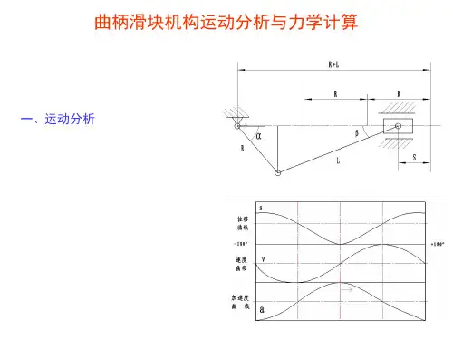
一、相关参数
在图1所示的曲柄滑块机构中,已知各构件的尺寸分别为
mm l 1001=,mm l 3002=,s rad /101=ω,试确定连杆2和滑块3的位移、速度和加速度,并绘制出运动线图。
图1 曲柄滑块机构
二、数学模型的建立
1、位置分析
为了对机构进行运动分析,将各构件表示为矢量,可写出各杆矢所构成的封闭矢量方程。
将各矢量分别向X 轴和Y 轴进行投影,得
0sin sin cos cos 22112211=+=+θθθθl l S l l C (1)
由式(1)得
2、速度分析
将式(1)对时间t 求导,得速度关系 C v l l l l =--=+222111222111sin sin 0
cos cos θωθωθωθω (2)
将(2)式用矩阵形式来表示,如下所示
⎥⎦⎤⎢⎣⎡-=⎥⎦⎤⎢⎣⎡⎥⎦⎤⎢⎣⎡-11
11122222cos sin . 0 cos 1 sin θθωωθθl l v l l C (3) 3、加速度分析
将(2)对时间t 求导,得加速度关系
三、计算程序
1、主程序
%1.输入已知数据
clear;
l1=;
l2=;
e=0;
hd=pi/180;
du=180/pi;
omega1=10;
alpha1=0;
%2.曲柄滑块机构运动计算
for n1=1:721
theta1(n1)=(n1-1)*hd;
%调用函数slider_crank计算曲柄滑块机构位移、速度、加速度
[theta2(n1),s3(n1),omega2(n1),v3(n1),alpha2(n1),a3(n1)]=slider_crank(theta1(n1),omega1,alpha1 ,l1,l2,e);
end
figure(1);
n1=0:720;
subplot(2,3,1)
plot(n1,theta2*du);
title('连杆转角位移线图');
xlabel('曲柄转角\theta_1/\circ');
ylabel('连杆角位移/\circ');
grid on
subplot(2,3,2)
plot(n1,omega2);
title('连杆角速度运动线图');
xlabel('曲柄转角\theta_1/\circ');
ylabel('连杆角速度/rad\cdots^{-1}');
grid on
subplot(2,3,3)
plot(n1,alpha2);
title('连杆角加速度运动线图');
xlabel('曲柄转角\theta_1/\circ');
ylabel('连杆角加速度/rad\cdots^{-2}');
grid on
subplot(2,3,4)
plot(n1,s3);
title('滑块位移线图');
xlabel('曲柄转角\theta_1/\circ');
ylabel('滑块位移/\m');
grid on
subplot(2,3,5)
plot(n1,v3);
title('滑块速度运动线图');
xlabel('曲柄转角\theta_1/\circ');
ylabel('滑块速度/m\cdots^{-1}');
grid on
subplot(2,3,6)
plot(n1,a3);
title('滑块加速度运动线图');
xlabel('曲柄转角\theta_1/\circ');
ylabel('滑块加速度/m\cdots^{-2}');
grid on
2、子程序
function[theta2,s3,omega2,v3,alpha2,a3]=slider_crank(theta1,omega1,alpha1,l1,l2,e);
%计算连杆2的角位移和滑块3的线位移
s3=l1*cos(theta1)+l2*cos(theta2);theta2=asin((e-l1*sin(theta1))/l2);
%计算连杆2的角速度和滑块3的线速度
A=[l2*sin(theta2),1;-l2*cos(theta2),0];
B=[-l1*sin(theta1);l1*cos(theta1)];
omega=A\(omega1*B);
omega2=omega(1);
v3=omega(2);
%计算连杆2的角加速度和滑块3的线加速度
At=[omega2*l2*cos(theta2),0;omega2*l2*sin(theta2),0];
Bt=[-omega1*l1*cos(theta1);-omega1*l1*sin(theta1)];
alpha=A\(-At*omega+alpha1*B+omega1*Bt);
alpha2=alpha(1);
a3=alpha(2);
四、程序运行结果及分析
图2 运动规律曲线图
从仿真曲线可以看出,当曲柄以w1=10rad/s匀速转动时,连杆的转角位移变化范围大约在-20~20度之间,在90°或270°有极值,呈反正弦变化趋势;连杆的角速度变化范围大约在~s,在0°或180°有极值,成反余弦变化趋势;连杆角加速度变化范围大约在-35~35rad/s2,在90°或270°有极值,呈正弦变化趋势。
滑块位移变化范围大约在~0.4m之间,在0°或180°有极值,呈反余弦变化趋势;滑块速度变化范围大约在-1~1m/s之间,大致上呈正弦变化趋势;滑块加速度变化范围大约在-13~6.9m/s2,在0°或180°有极值。