有限元分析报告报告材料法英文简介
- 格式:doc
- 大小:42.00 KB
- 文档页数:11
水利枢纽工程有限元分析报告水利枢纽工程有限元分析报告一、引言本报告旨在介绍水利枢纽工程有限元分析的基本原理、方法及过程,通过对具体水利枢纽工程的有限元模型建立、边界条件、载荷工况等进行分析,评估水利枢纽工程的整体和局部应力、应变、位移等响应,为水利枢纽工程的优化设计、安全运行提供理论支持。
二、水利枢纽工程有限元分析原理有限元分析(Finite Element Analysis,FEA)是一种数值计算方法,通过将连续的求解域离散化为由有限个单元组成的集合体,从而对复杂问题进行简化处理。
水利枢纽工程作为典型的复杂结构体系,利用有限元分析方法能够有效地解决工程中的问题。
三、水利枢纽工程有限元模型建立1.模型建立流程本报告以某实际水利枢纽工程为例,介绍有限元模型建立的流程。
具体流程如下:(1)搜集工程资料:收集水利枢纽工程的几何尺寸、材料属性、载荷工况等基本信息。
(2)划分网格:根据水利枢纽工程的几何形状和特点,将模型划分为若干个单元网格,每个单元网格由节点连接。
(3)建立模型:根据搜集的工程资料和划分的网格,利用有限元分析软件建立水利枢纽工程的有限元模型。
(4)施加边界条件和载荷:根据实际工程的约束和载荷情况,对有限元模型施加边界条件和载荷。
(5)进行计算:利用有限元分析软件进行计算,获得水利枢纽工程的应力、应变、位移等响应。
2.模型简化与处理在建立水利枢纽工程有限元模型时,需要对实际工程进行适当的简化和处理。
例如,可以将材料的非线性特性进行线性化处理,忽略次要因素对计算结果的影响。
四、水利枢纽工程有限元分析结果1.应力、应变、位移云图通过有限元分析软件的可视化功能,可以得到水利枢纽工程的应力、应变、位移云图。
从云图上可以清楚地看出水利枢纽工程的最大应力、应变和位移的位置和大小。
五、水利枢纽工程有限元分析结论与建议1.分析结论根据上述水利枢纽工程有限元分析结果,可以得出以下结论:(1)该水利枢纽工程的整体应力、应变和位移响应均在可接受范围内,说明该工程的结构设计合理,能够安全运行。
有限元分析过程范文有限元分析(Finite Element Analysis,简称FEA)是一种通过将复杂的工程问题划分成简单的有限元单元,并对这些单元进行建模和分析的数值计算方法。
它广泛应用于结构力学、流体力学、热传导等领域,对于解决复杂的实际工程问题起到了至关重要的作用。
首先,进行几何建模,即将实际问题抽象成一个适合分析的几何模型。
这需要对待分析的实际工件进行几何形状的描述和选择合适的坐标系。
对于简单的几何形状,可以直接使用相关软件进行建模;对于复杂的几何形状,可以使用CAD软件进行建模,并将其导入到有限元分析软件中。
接下来,进行网格划分。
网格是指用一系列简单的形状(如三角形、四边形)将整个几何模型分割成小的有限元单元。
通常情况下,边界和模型的几何特征会指导网格划分。
网格的划分需要满足一定的准则,如尽量均匀划分、尽量符合实际几何形状等。
完成网格划分后,需要为每个有限元单元定义材料属性和边界条件。
材料属性包括弹性模量、泊松比、密度等。
边界条件包括施加在模型上的力、力矩、位移约束等。
这些参数的选取需要结合实际工程问题的特点和分析的目标进行。
对于线性问题,可以直接使用有限元法求解线性方程组;对于非线性问题,需要使用迭代法进行求解。
求解过程中,计算机会根据有限元模型的离散特点,将其转化为代数形式的方程组,并通过迭代求解方法来得到数值解。
最后,进行结果后处理。
结果后处理是用于分析和展示有限元模型的结果,包括模型的应力应变分布、位移分布、变形等。
常见的结果展示方式有等值线图、变形云图等。
通过对结果的分析和比较,可以对模型的工程性能进行评价。
当然,有限元分析过程中还需要进行收敛性和稳定性分析,以保证结果的准确性和可靠性。
此外,有限元模型的建立和验证也是十分重要的,需要对模型进行合理性检验和准确性验证。
总之,有限元分析是一种重要的工程分析工具,通过将实际工程问题离散化为有限元单元,并进行数值求解,可以获得工程问题的准确解。

有限元分析中英文对照资料The finite element analysisFinite element method, the solving area is regarded as made up of many small in the node connected unit (a domain), the model gives the fundamental equation of sharding (sub-domain) approximation solution, due to the unit (a domain) can be divided into various shapes and sizes of different size, so it can well adapt to the complex geometry, complex material properties and complicated boundary conditions Finite element model: is it real system idealized mathematical abstractions. Is composed of some simple shapes of unit, unit connection through the node, and under a certain load.Finite element analysis: is the use of mathematical approximation method for real physical systems (geometry and loading conditions were simulated. And by using simple and interacting elements, namely unit, can use a limited number of unknown variables to approaching infinite unknown quantity of the real system.Linear elastic finite element method is a ideal elastic body as the research object, considering the deformation based on small deformation assumption of. In this kindof problem, the stress and strain of the material is linear relationship, meet the generalized hooke's law; Stress and strain is linear, linear elastic problem boils down to solving linear equations, so only need less computation time. If the efficient method of solving algebraic equations can also help reduce the duration of finite element analysis.Linear elastic finite element generally includes linear elastic statics analysis and linear elastic dynamics analysis from two aspects. The difference between the nonlinear problem and linear elastic problems:1) nonlinear equation is nonlinear, and iteratively solving of general;2) the nonlinear problem can't use superposition principle;3) nonlinear problem is not there is always solution, sometimes even no solution. Finite element to solve the nonlinear problem can be divided into the following three categories:1) material nonlinear problems of stress and strain is nonlinear, but the stress and strain is very small, a linear relationship between strain and displacement at this time, this kind of problem belongs to the material nonlinear problems. Due to theoretically also cannot provide the constitutive relation can be accepted, so, general nonlinear relations between stress and strain of the material based on the test data, sometimes, to simulate the nonlinear material properties available mathematical model though these models always have their limitations. More important material nonlinear problems in engineering practice are: nonlinear elastic (including piecewise linear elastic, elastic-plastic and viscoplastic, creep, etc.2) geometric nonlinear geometric nonlinear problems are caused due to the nonlinear relationship between displacement. When the object the displacement is larger, the strain and displacement relationship is nonlinear relationship. Research on this kind of problemIs assumes that the material of stress and strain is linear relationship. It consists of a large displacement problem of large strain and large displacement little strain. Such as the structure of the elastic buckling problem belongs to the large displacement little strain, rubber parts forming process for large strain.3) nonlinear boundary problem in the processing, problems such as sealing, the impact of the role of contact and friction can not be ignored, belongs to the highly nonlinear contact boundary. At ordinary times some contact problems, such as gear, stamping forming, rolling, rubber shock absorber, interference fit assembly, etc., when a structure and another structure or external boundary contact usually want to consider nonlinear boundary conditions. The actual nonlinear may appear at the same time these two or three kinds of nonlinear problems.Finite element theoretical basisFinite element method is based on variational principle and the weighted residual method, and the basic solving thought is the computational domain is divided into a finite number of non-overlapping unit, within each cell, select some appropriate nodes as solving the interpolation function, the differential equation of the variables in the rewritten by the variable or its derivative selected interpolation node value and the function of linear expression, with the aid of variational principle or weighted residual method, the discrete solution of differential equation. Using different forms of weight function and interpolation function, constitute different finite element methods. 1. The weighted residual method and the weighted residual method of weighted residual method of weighted residual method: refers to the weighted function is zero using make allowance for approximate solution of the differential equation method is called the weighted residual method. Is a kind of directly from the solution of differential equation and boundary conditions, to seek the approximate solution of boundary value problems of mathematical methods. Weighted residual method is to solve the differential equation of the approximate solution of a kind of effective method. Hybrid method for the trial function selected is the most convenient, but under the condition of the same precision, the workload is the largest. For internal method and the boundary method basis function must be made in advance to meet certain conditions, the analysis of complex structures tend to have certain difficulty, but the trial function is established, the workload is small. No matter what method is used, when set up trial function should be paid attention to are the following:(1) trial function should be composed of a subset of the complete function set. Have been using the trial function has the power series and trigonometric series, spline functions, beisaier, chebyshev, Legendre polynomial, and so on.(2) the trial function should have until than to eliminate surplus weighted integral expression of the highest derivative low first order derivative continuity.(3) the trial function should be special solution with analytical solution of the problem or problems associated with it. If computing problems with symmetry, should make full use of it. Obviously, any independent complete set of functions can be used as weight function. According to the weight function of the different options fordifferent weighted allowance calculation method, mainly include: collocation method, subdomain method, least square method, moment method and galerkin method. The galerkin method has the highest accuracy.Principle of virtual work: balance equations and geometric equations of the equivalent integral form of "weak" virtual work principles include principle of virtual displacement and virtual stress principle, is the floorboard of the principle of virtual displacement and virtual stress theory. They can be considered with some control equation of equivalent integral "weak" form. Principle of virtual work: get form any balanced force system in any state of deformation coordinate condition on the virtual work is equal to zero, namely the system of virtual work force and internal force of the sum of virtual work is equal to zero. The virtual displacement principle is the equilibrium equation and force boundary conditions of the equivalent integral form of "weak"; Virtual stress principle is geometric equation and displacement boundary condition of the equivalent integral form of "weak". Mechanical meaning of the virtual displacement principle: if the force system is balanced, they on the virtual displacement and virtual strain by the sum of the work is zero. On the other hand, if the force system in the virtual displacement (strain) and virtual and is equal to zero for the work, they must balance equation. Virtual displacement principle formulated the system of force balance, therefore, necessary and sufficient conditions. In general, the virtual displacement principle can not only suitable for linear elastic problems, and can be used in the nonlinear elastic and elastic-plastic nonlinear problem.Virtual mechanical meaning of stress principle: if the displacement is coordinated, the virtual stress and virtual boundary constraint counterforce in which they are the sumof the work is zero. On the other hand, if the virtual force system in which they are and is zero for the work, they must be meet the coordination. Virtual stress in principle, therefore, necessary and sufficient condition for the expression of displacement coordination. Virtual stress principle can be applied to different linear elastic and nonlinear elastic mechanics problem. But it must be pointed out that both principle of virtual displacement and virtual stress principle, rely on their geometric equation and equilibrium equation is based on the theory of small deformation, they cannot be directly applied to mechanical problems based on large deformation theory. 3,,,,, the minimum total potential energy method of minimum total potential energy method, the minimum strain energy method of minimum total potential energy method, the potential energy function in the object on the external load will cause deformation, the deformation force during the work done in the form of elastic energy stored in the object, is the strain energy.The convergence of the finite element method, the convergence of the finite element method refers to when the grid gradually encryption, the finite element solution sequence converges to the exact solution; Or when the cell size is fixed, the more freedom degree each unit, the finite element solutions tend to be more precise solution. Convergence condition of the convergence condition of the finite element finite element convergence condition of the convergence condition of the finite element finite element includes the following four aspects: 1) within the unit, the displacement function must be continuous. Polynomial is single-valued continuous function, sochoose polynomial as displacement function, to ensure continuity within the unit. 2) within the unit, the displacement function must include often strain. Total can be broken down into each unit of the state of strain does not depend on different locations within the cell strain and strain is decided by the point location of variables. When the size of the units is enough hours, unit of each point in the strain tend to be equal, unit deformation is uniform, so often strain becomes the main part of the strain. To reflect the state of strain unit, the unit must include the displacement functions often strain. 3) within the unit, the displacement function must include the rigid body displacement. Under normal circumstances, the cell for a bit of deformation displacement and displacement of rigid body displacement including two parts. Deformation displacement is associated with the changes in the object shape and volume, thus producing strain; The rigid body displacement changing the object position, don't change the shape and volume of the object, namely the rigid body displacement is not deformation displacement. Spatial displacement of an object includes three translational and three rotational displacement, a total of six rigid body displacements. Due to a unit involved in the other unit, other units do rigid body displacement deformation occurs will drive unit, thus, to simulate real displacement of a unit, assume that the element displacement function must include the rigid body displacement. 4) the displacement function must be coordinated in public boundary of the adjacent cell. For general unit of coordination is refers to the adjacent cell in public node have the same displacement, but also have the same displacement along the edge of the unit, that is to say, to ensure that the unit does not occur from cracking and invade the overlap each other. To do this requires the function on the common boundary can be determined by the public node function value only. For general unit and coordination to ensure the continuity of the displacement of adjacent cell boundaries. However, between the plate and shell of the adjacent cell, also requires a displacement of the first derivative continuous, only in this way, to guarantee the strain energy of the structure is bounded. On the whole, coordination refers to the public on the border between neighboring units satisfy the continuity conditions. The first three, also called completeness conditions, meet the conditions of complete unit is complete unit; Article 4 is coordination requirements, meet the coordination unit coordination unit; Otherwise known as the coordinating units. Completeness requirement is necessary for convergence, all four meet, constitutes a necessary and sufficient condition for convergence. In practical application, to make the selected displacement functions all meet the requirements of completeness and harmony, it is difficult in some cases can relax the requirement for coordination. It should be pointed out that, sometimes the coordination unit than its corresponding coordination unit, its reason lies in the nature of the approximate solution. Assumed displacement function is equivalent to put the unit under constraint conditions, the unit deformation subject to the constraints, this just some alternative structure compared to the real structure. But the approximate structure due to allow cell separation, overlap, become soft, the stiffness of the unit or formed (such as round degree between continuous plate unit in the unit, and corner is discontinuous, just to pin point) for the coordination unit, the error of these two effects have the possibility of cancellation, so sometimes use thecoordination unit will get very good results. In engineering practice, the coordination of yuan must pass to use "small pieces after test". Average units or nodes average processing method of stress stress average units or nodes average processing method of stress average units or nodes average processing method of stress of the unit average or node average treatment method is the simplest method is to take stress results adjacent cell or surrounding nodes, the average value of stress.1. Take an average of 2 adjacent unit stress. Take around nodes, the average value of stressThe basic steps of finite element method to solve the problemThe structural discretization structure discretization structure discretization structure discretization to discretization of the whole structure, will be divided into several units, through the node connected to each other between the units; 2. The stiffness matrix of each unit and each element stiffness matrix and the element stiffness matrix and the stiffness matrix of each unit (3) integrated global stiffness matrix integrated total stiffness matrix integrated overall stiffness matrix integrated total stiffness matrix and write out the general balance equations and write out the general balance equations and write out the general balance equations and write a general equation 4. Introduction of supporting conditions, the displacement of each node 5. Calculate the stress and strain in the unit to get the stress and strain of each cell and the cell of the stress and strain and the stress and strain of each cell.For the finite element method, the basic ideas and steps can be summarized as: (1) to establish integral equation, according to the principle of variational allowance and the weight function or equation principle of orthogonalization, establishment and integral expression of differential equations is equivalent to the initial-boundary value problem, this is the starting point of the finite element method. Unit (2) the area subdivision, according to the solution of the shape of the area and the physical characteristics of practical problems, cut area is divided into a number of mutual connection, overlap of unit. Regional unit is divided into finite element method of the preparation, this part of the workload is bigger, in addition to the cell and node number and determine the relationship between each other, also said the node coordinates, at the same time also need to list the natural boundary and essential boundary node number and the corresponding boundary value. (3) determine the unit basis function, according to the unit and the approximate solution of node number in precision requirement, choose meet certain interpolation condition basis function interpolation function as a unit. Basis function in the finite element method is selected in the unit, due to the geometry of each unit has a rule in the selection of basis function can follow certain rules. (4) the unit will be analysis: to solve the function of each unit with unit basis functions to approximate the linear combination of expression; Then approximate function generation into the integral equation, and the unit area integral, can be obtained with undetermined coefficient (i.e., cell parameter value) of each node in the algebraic equations, known as the finite element equation.(5) the overall synthesis: after the finite element equation, the area of all elements inthe finite element equation according to certain principles of accumulation, the formation of general finite element equations. (6) boundary condition processing: general boundary conditions there are three kinds of form, divided into the essential boundary conditions (dirichlet boundary condition) and natural boundary conditions (Riemann boundary conditions) and mixed boundary conditions (cauchy boundary conditions). Often in the integral expression for natural boundary conditions, can be automatically satisfied. For essential boundary conditions and mixed boundary conditions, should be in a certain method to modify general finite element equations satisfies. Solving finite element equations (7) : based on the general finite element equations of boundary conditions are fixed, are all closed equations of the unknown quantity, and adopt appropriate numerical calculation method, the function value of each node can be obtained.有限元分析有限元法求解区域是由许多小的节点连接单元(域),该模型给出了切分的基本方程(子域名)的近似解,由于单位(域)可以分为不同的形状和大小不同的尺寸,所以它能很好的适应复杂的几何形状、材料特性和边界条件复杂,复杂有限元模型:它是真实系统的理想化的数学抽象。
有限元分析报告报告材料英文文献The Basics of FEA Procedure有限元分析程序的基本知识2.1 IntroductionThis chapter discusses the spring element, especially for the purpose of introducing various concepts involved in use of the FEA technique.本章讨论了弹簧元件,特别是用于引入使用的有限元分析技术的各种概念的目的A spring element is not very useful in the analysis of real engineering structures; however, it represents a structure in an ideal form for an FEA analysis. Spring element doesn’t require discretization (division into smaller elements) and follows the basic equation F = ku.在分析实际工程结构时弹簧元件不是很有用的;然而,它代表了一个有限元分析结构在一个理想的形式分析。
弹簧元件不需要离散化(分裂成更小的元素)只遵循的基本方程F = ku We will use it solely for the purpose of developing an understanding of FEA concepts and procedure.我们将使用它的目的仅仅是为了对开发有限元分析的概念和过程的理解。
2.2 Overview概述Finite Element Analysis (FEA), also known as finite element method (FEM) is based on the concept that a structure can be simulated by the mechanicalbehavior of a spring in which the applied force is proportional to the displacement of the spring and the relationship F = ku is satisfied.有限元分析(FEA),也称为有限元法(FEM),是基于一个结构可以由一个弹簧的力学行为模拟的应用力弹簧的位移成正比,F = ku切合的关系。
一、有限单元法的基本原理有限单元法(The Finite Element Method)简称有限元(FEM),它是利用电子计算机进行的一种数值分析方法。
它在工程技术领域中的应用十分广泛,几乎所有的弹塑性结构静力学和动力学问题都可用它求得满意的数值结果。
有限元方法的基本思路是:化整为零,积零为整。
即应用有限元法求解任意连续体时,应把连续的求解区域分割成有限个单元,并在每个单元上指定有限个结点,假设一个简单的函数(称插值函数)近似地表示其位移分布规律,再利用弹塑性理论中的变分原理或其他方法,建立单元结点的力和位移之间的力学特性关系,得到一组以结点位移为未知量的代数方程组,从而求解结点的位移分量. 进而利用插值函数确定单元集合体上的场函数。
由位移求出应变, 由应变求出应力二、ABAQUS有限元分析过程有限元分析过程可以分为以下几个阶段1.建模阶段: 建模阶段是根据结构实际形状和实际工况条件建立有限元分析的计算模型――有限元模型,从而为有限元数值计算提供必要的输入数据。
有限元建模的中心任务是结构离散,即划分网格。
但是还是要处理许多与之相关的工作:如结构形式处理、集合模型建立、单元特性定义、单元质量检查、编号顺序以及模型边界条件的定义等。
2.计算阶段:计算阶段的任务是完成有限元方法有关的数值计算。
由于这一步运算量非常大,所以这部分工作由有限元分析软件控制并在计算机上自动完成3.后处理阶段: 它的任务是对计算输出的结果惊醒必要的处理,并按一定方式显示或打印出来,以便对结构性能的好坏或设计的合理性进行评估,并作为相应的改进或优化,这是惊醒结构有限元分析的目的所在。
下列的功能模块在ABAQUS/CAE操作整个过程中常常见到,这个表简明地描述了建立模型过程中要调用的每个功能模块。
“Part(部件)用户在Part模块里生成单个部件,可以直接在ABAQUS/CAE环境下用图形工具生成部件的几何形状,也可以从其它的图形软件输入部件。
Abaqus有限元分析报告1. 简介在工程领域中,有限元分析是一种常见的数值计算方法,用于解决结构力学问题。
Abaqus是一种常用的有限元分析软件,它提供了强大的求解能力和丰富的后处理功能。
本文档将介绍一个基于Abaqus的有限元分析报告。
2. 模型建立在开始分析之前,我们首先需要建立一个合适的模型。
模型的建立通常包括几何建模、材料属性定义、边界条件设置等步骤。
在本次分析中,我们将以一个简单的弹性力学问题为例进行说明。
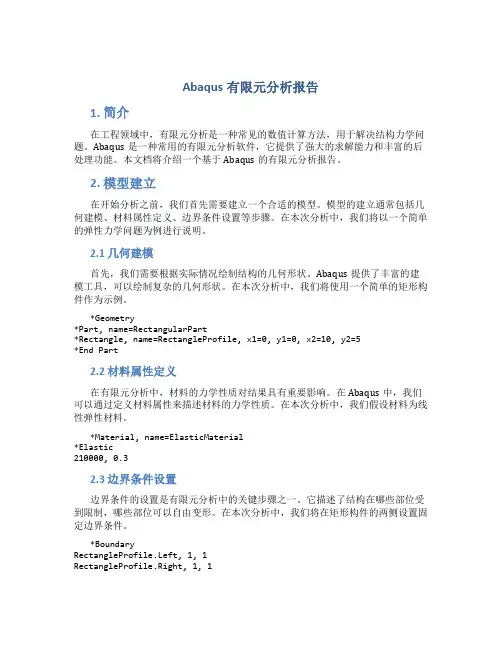
2.1 几何建模首先,我们需要根据实际情况绘制结构的几何形状。
Abaqus提供了丰富的建模工具,可以绘制复杂的几何形状。
在本次分析中,我们将使用一个简单的矩形构件作为示例。
*Geometry*Part, name=RectangularPart*Rectangle, name=RectangleProfile, x1=0, y1=0, x2=10, y2=5*End Part2.2 材料属性定义在有限元分析中,材料的力学性质对结果具有重要影响。
在Abaqus中,我们可以通过定义材料属性来描述材料的力学性质。
在本次分析中,我们假设材料为线性弹性材料。
*Material, name=ElasticMaterial*Elastic210000, 0.32.3 边界条件设置边界条件的设置是有限元分析中的关键步骤之一。
它描述了结构在哪些部位受到限制,哪些部位可以自由变形。
在本次分析中,我们将在矩形构件的两侧设置固定边界条件。
*BoundaryRectangleProfile.Left, 1, 1RectangleProfile.Right, 1, 13. 求解过程在完成模型建立后,我们可以开始进行有限元分析的求解过程。
Abaqus提供了多种求解器,可以选择适合问题的求解算法和计算资源。
3.1 求解器选择在Abaqus中,我们可以通过选择合适的求解器来进行求解。
常见的求解器包括静态求解器、动态求解器等。

有限元基础理论读书报告有限元法(Finite Element Method,FEM),是计算力学中的一种重要的方法,它是20世纪50年代末60年代初兴起的应用数学、现代力学及计算机科学相互渗透、综合利用的边缘科学。
有限元法最初应用在工程科学技术中,用于模拟并且解决工程力学、热学、电磁学等物理问题。
对于过去用解析方法无法求解的问题和边界条件及结构形状都不规则的复杂问题,有限元法则是一种有效的分析方法。
近年来随着计算机技术的普及和计算速度的不断提高,有限元分析在工程设计和分析中得到了越来越广泛的重视,已经成为解决复杂的工程分析计算问题的有效途径,现在从汽车到航天飞机几乎所有的设计制造都已离不开有限元分析计算,其在机械制造、材料加工、航空航天、汽车、土木建筑、电子电器,国防军工,船舶,铁道,石化,能源,科学研究等各个领域的广泛使用已使设计水平发生了质的飞跃,主要表现在以下几个方面:(1)增加产品和工程的可靠性(2)在产品的设计阶段发现潜在的问题(3)经过分析计算,采用优化设计方案,降低原材料成本(4)模拟试验方案,减少试验次数,从而减少试验经费有限元法的基本思想有限元法的基本思想是先将研究对象的连续求解区域离散为一组有限个且按一定方式相互联结在一起的单元组合体。
由于单元能按不同的联结方式进行组合,且单元本身又可以有不同形状,因此可以模拟成不同几何形状的求解小区域;然后对单元(小区域)进行力学分析,最后再整体分析。
这种化整为零,集零为整的方法就是有限元的基本思路。
物体离散化将某个工程结构离散为由各种单元组成的计算模型,这一步称作单元剖分。
离散后单元与单元之间利用单元的节点相互连接起来;单元节点的设置、性质、数目等应视问题的性质,描述变形形态的需要和计算进度而定(一般情况单元划分越细则描述变形情况越精确,即越接近实际变形,但计算量越大)。
所以有限元中分析的结构已不是原有的物体或结构物,而是同新材料的由众多单元以一定方式连接成的离散物体。
FEA分析报告1. 引言本报告旨在对某个系统(下简称系统)进行有限元分析(Finite Element Analysis, FEA)。
通过对系统的结构和性能进行分析,旨在得出一些关键参数,以指导系统的设计和优化。
2. 系统描述系统由若干个组件组成,每个组件都具有特定的功能和结构特征。
为了分析系统的性能,我们将系统进行了细分,每个组件都被离散化为有限的单元。
3. 模型建立为了进行有限元分析,首先需要建立系统的数学模型。
我们根据系统的结构和特性,采用了一种常用的有限元模型。
将每个组件离散化为单元,并通过节点将这些单元连接起来,形成系统的有限元模型。
4. 材料特性系统的材料特性是进行有限元分析的重要参数。
我们根据实际情况,为每个组件选择了合适的材料,并确定了其材料特性。
这些特性包括材料的弹性模量、泊松比等。
5. 载荷定义为了模拟系统的工作条件,我们需要对系统施加适当的载荷。
通过分析系统的工作环境和使用情况,我们定义了一系列的载荷,并将其应用于有限元模型上。
6. 约束条件在实际应用中,系统往往受到一定的约束条件限制。
为了准确模拟系统的实际工作情况,我们对有限元模型施加了适当的约束条件。
这些约束条件包括固定支撑、位移限制等。
7. 分析结果通过对系统进行有限元分析,我们得到了一系列的分析结果。
这些结果包括各个组件的应力分布、变形情况等。
通过分析这些结果,我们可以评估系统的性能,并确定是否需要进行设计优化。
8. 结论通过本次有限元分析,我们对系统的性能进行了评估,并得出了一些结论。
根据分析结果,我们可以确定系统的强度和稳定性是否满足设计要求,并提出了一些建议和改进方案。
9. 参考文献在本次分析过程中,我们参考了一些相关的文献和资料。
这些参考文献对我们的分析工作起到了重要的指导作用。
以上是对系统进行有限元分析的一份报告,通过分析系统的结构和性能,我们可以更好地指导系统的设计和优化工作。
有限元分析是一种强大的工具,可以帮助工程师和设计师更好地理解系统的行为,从而做出更合理的决策。
有限元分析报告1. 引言有限元分析(Finite Element Analysis)是一种数值计算方法,用于求解工程和科学领域中的复杂问题。
它利用离散化技术将连续问题转化为离散问题,并应用数值算法进行求解。
本报告将主要介绍有限元分析的基本原理、应用和分析结果。
2. 有限元分析基本原理有限元分析的基本原理是将求解区域划分为互不重叠的有限个小单元,并将问题转化为在每个小单元内求解。
这些小单元通常为简单的几何形状,如三角形或四边形。
然后,在每个小单元内应用适当的数学模型和力学方程,得到相应的微分方程。
接着,通过对每个小单元的微分方程进行积分,并利用边界条件和连续性条件,得到整个求解区域的离散形式。
最后,通过求解离散形式的方程组,得到整个系统的解。
3. 有限元分析应用有限元分析在工程领域有着广泛的应用。
以下是几个典型的应用案例:3.1 结构分析有限元分析在结构分析中的应用非常广泛,可以用于确定结构的强度和刚度,评估结构的安全性,并进行结构优化设计。
通过对结构施加正确的边界条件和加载条件,可以得到结构的应力、应变和变形等重要信息。
3.2 流体力学分析有限元分析在流体力学分析中的应用可以用于模拟流体的流动和传热过程,例如气体和液体的流动、传热设备的设计优化等。
通过分析流体系统的流速、压力和温度等参数,可以对流体系统的性能和行为进行合理评估。
3.3 热力学分析有限元分析在热力学分析中的应用可以用于分析和优化热传导、热辐射和热对流等热问题。
通过模拟物体的温度分布和热流动,可以评估物体的热性能和热耗散效果。
4. 有限元分析结果有限元分析的计算结果可以提供丰富的信息,帮助工程师和科学家理解和优化系统的行为和性能。
以下是一些常见的有限元分析结果:4.1 应力分布通过有限元分析,可以得到结构或部件内的应力分布情况。
这对于评估结构的强度和安全性非常重要,并可以指导优化设计。
4.2 变形分析有限元分析可以给出结构或部件的变形情况。
ANSYS有限元分析报告1. 引言有限元分析(Finite Element Analysis, FEA)是一种常用的工程分析方法,可以用于预测材料和结构在各种工况下的行为和性能。
本报告旨在通过使用ANSYS软件进行有限元分析,对某一具体的工程问题进行模拟和分析,并得出相应的结论和建议。
2. 问题描述本次有限元分析的问题是研究某结构在受载情况下的应力分布和变形情况。
具体而言,我们关注的结构是一个柱形零件,其材料为XXX,尺寸为XXX。
该结构在受到垂直向下的均布载荷时,会发生弯曲变形和应力集中现象。
我们的目标是通过有限元方法对该结构进行分析,预测其应力分布情况,并评估其承载能力。
3. 模型建立我们使用ANSYS软件来建立和分析该结构的有限元模型。
首先,我们将导入该零件的几何数据,然后通过ANSYS的建模工具创建相应的有限元模型。
在建立模型的过程中,我们需要注意几何尺寸、材料特性、约束条件和加载方式等参数的设定,以确保模型的准确性和可靠性。
4. 材料属性和加载条件在进行有限元分析之前,我们需要确定材料的特性和加载条件。
根据提供的信息,我们将采用XXX材料的力学特性进行模拟。
同时,我们假设该结构受到均布载荷的作用,其大小为XXX。
这些参数将在后续的分析中使用。
5. 模型网格划分在进行有限元分析之前,我们需要对模型进行网格划分。
网格的密度和质量将直接影响分析结果的准确性和计算效率。
在本次分析中,我们将采用适当的网格划分策略,以满足准确性和计算效率的要求。
6. 模型分析和结果通过ANSYS软件进行有限元分析后,我们得到了该结构在受载情况下的应力分布和变形情况。
根据分析结果,我们可以观察到应力集中区域和变形程度,并根据材料的特性进行评估。
同时,我们可以通过对加载条件的变化进行分析,预测该结构的承载能力和安全系数。
7. 结论和建议根据有限元分析的结果,我们得出以下结论和建议:•该结构在受均布载荷作用下发生应力集中现象,需要对其进行加强和优化设计。
有限元分析报告有限元分析(Finite Element Analysis, FEA)是一种工程分析方法,通过对结构进行离散建模,然后对每个离散单元进行力学分析,最终得出整个结构的应力、位移等结果。
本报告将对某桥梁结构进行有限元分析,并对分析结果进行详细说明。
1. 结构建模。
首先,我们对桥梁结构进行了建模。
在建模过程中,我们考虑了桥梁的几何形状、材料属性、边界条件等因素。
通过有限元软件,我们将桥梁结构离散为多个单元,并建立了相应的数学模型。
在建模过程中,我们尽可能地考虑了结构的复杂性,以保证分析结果的准确性。
2. 荷载分析。
在建立了结构模型之后,我们对桥梁施加了不同的荷载,包括静载、动载等。
通过有限元分析,我们得出了桥梁在不同荷载下的应力、位移等结果。
同时,我们还对结构的疲劳寿命进行了评估,以确保结构在使用过程中的安全性。
3. 结果分析。
根据有限元分析的结果,我们对桥梁结构的性能进行了分析。
我们发现,在某些局部区域,结构存在应力集中现象;同时,在某些荷载作用下,结构的位移超出了设计要求。
基于这些分析结果,我们对结构的设计提出了一些改进建议,以提高结构的安全性和稳定性。
4. 结论。
通过有限元分析,我们得出了对桥梁结构设计的一些结论。
我们发现,在当前设计下,结构存在一些潜在的安全隐患,需要进行一定的改进。
同时,我们还对结构的使用寿命进行了评估,提出了一些建议。
通过本次有限元分析,我们对桥梁结构的性能有了更深入的了解,为后续的设计和改进提供了重要参考。
综上所述,本报告通过有限元分析,对某桥梁结构的性能进行了评估,并提出了一些改进建议。
有限元分析作为一种重要的工程分析方法,为工程结构的设计和改进提供了重要的技术支持。
希望本报告能对相关工程技术人员提供一定的参考价值。
有限元分析与应用上机实验报告学院:机电工程学院专业:机械工程班级:硕士1606班*名:***学号: *********指导教师:***日期: 2016.12.021.QuestionFig.1. Schematic diagram of herringbone roof truss.Question: The geometric dimensions of the chevron roof is shown in Fig.1,you should analyze it by statics,as a result you should give the displacement and axial force and axial force diagram of the deformation diagram.Conditions: The ends of the roof truss were fixed, the sectional area of the truss is 0.01m2, elastic modulus is2.0×1011 N/m2, poisson's ratio is 0.3.2.The software usedANSYS Finite element software (APDL 15.0)3.Solving processPoint 1 was choosed as the Coordinate point, horizontal to the right was the X axis,the upright direction is choosed as the Y axis to create a coordinate system. The nodes was numbered as shown in Figure 1,node 1 and node 5 was fixed,and the force on node 6,7,8 was is 1k N,the direction is opposite to the Y-axis3.1 The preparatory work before analysis(1)Specify the new file name. Select Utility>Menu> File>Change Jobname, then pop-up the dialog box Change Jobname, input the the working file name ‘2D-sp’ in the Enter New Jobname, click OK to finish the difinition, as shown in Fig.2.Fig.2. The difinition of working file name.(2)Specify a new title. Select Utility>Menu>File>Change Title,then pop-up the dialog box Change Title, input the the file name ‘2D-sp pro’ in the Enter New Title, click OK to finish the difinition, as shown in Fig.3.Fig.3. The difinition of file name.(3)Re-refresh the graphics window.Select Utility>Menu>Plot>Replot, the defined information was displayed in the graphics window.(4)Define the structural analysis. Run the main menu Main Menu>Preferences,then choose the Structural, click OK to complete the definition of the analysis type , as shown in Fig.4.Fig.4. The definition of the structural analysis.3.2 Define the element typeRun the main menu Main Menu>Preprocessor>Element Type>Add, then pop-up the dialog box Element Types, click the button Add to build a new element type, then pop-up the dialog box Library of Element Types, choose Link first, and then select 3D finit stn 180(Link1),click the button OK to finish the definition of the element type, click the button Close to finish the settings, as shown in Fig.5.Fig.5. The definition of the element type.3.3 Define the real constantsRun the main menu Main Menu>Preprocessor>Real Constants Add, then pop-up the dialog box of real constants, click the button Add to come into the constant input dialog box, as shown in Fig.6. Input the sectional area of the truss (0.01m2) in AREA, click the button OK to finish the input of the real constants, as shown in Fig.7.Fig.6. Get into the instance constant dialog box.Fig.7. The definition of the real constants.3.4 Define the material propertiesRun the main menu Main Menu>Preprocessor>Material Props>Material Models,then pop-up the dialog box of material properties, and select Structure、Linear、Elastic、Isotropic, as shown in Fig.8.When the selection was completed, appeared the MaterialProperties input dialog box appears,then input elastic modulus 2e11 and the poisson's ratio 0.3, as shown in Fig.9, click OK to finish the input of the material properties.Fig.8. Get into the setting of material properties.Fig.9. The difinition of the material properties.3.5 Establish the analytical model(1)Create the nodes. The coordinates of the 1—8 nodes as shown in Table.1. Run the main menu Main Menu>Preprocessor> Modeling>Create>Nodes>In Active CS. The create node entry dialog box appears as shown in Fig.10. I nput the first node 1 and its’ x, y, z coordinate, then click Apply to finish the creating of the node. Similarly, create the nodes 2—8, click OK to finish the creating of the nodes, as shown in Fig.10.Table.1.The coordinates of geometry model nodes.Fig.10. The dialog box of nodes input.Fig.11. The creation of the nodes.The created nodes as shown below:(2)Created the bar unitRun the main menu MainMenu>Preprocessor>Modeling>Create >Elements>Auto Numbered>Thru Nodes, then pop-up the dialog box Element from Nodes, pick the nodes 1 and 2, click Apply to complete the first lever unit . Similarly, pick both ends of the rod in turn, click Apply to complete the lever unit, lastly click OK, as shown in Fig.12.Fig.12. Model establishment of the herringbone truss.3.6 Apply constraints and loads(1)Impose constraintsRun the main menu Main Menu>Solution>Define Loads>Apply>Structural> Displacement>On Nodes, the pick menu appears, select nodes 1 and 5 in turn, then click OK, the constraint definition dialog box appears,as shown in Fig.13. Choose All DOF to constrain all degrees of freedom,other items by default,then click the button OK to complete the constraint definition.Fig.13. Impose the constraints.(2)Apply the loadRun the main menu Main Menu>Solution>Define Loads>Apply>Structural> Force/Moment>On Nodes, the pick menu appears, select nodes 6, 7 and 8 in turn, click OK , then the load definitions dialog box appears,as shown in Fig.14. The load type is concentrated force FY. The value is -1000 , Then clickthe OK button to complete the application of the load.Fig.14. The application of the load.Figure after load application as shown below:3.7 SolutionRun the main menu Main Menu>Solution>Solve>Current LS, then pop-up the dialog box Solve Current Load Step, click STAT Command, then click STAT Command>File>Close toclose the STAT Command window, then click OK to finish the steps.Then the computer started the solution. The promption of "Solution is done" indicated that the solution was completed, click the button Close to finish the solution, as shown in Fig.15.Fig.15. The process of the solution.3.8 View the analysis results(1)Define the cell table. In ANSYS, some data can not be directly accessed, so we need to complete the definition of cell to access the results.Run the main menu Main Menu>General Postproc>Element Table>Define Table, then pop-up the dialog box, click the button Add. The unit table definition dialog box appeared, as shown in Fig.16.Fig.16a. The definition of the cell table.Fig.16b. The definition of the cell table.(2)Display the axial force (axial stress) diagram. Run the main menu Main Menu>General Postproc>Plot Results> Contour Plot>Elem Table. Then pop-up the cell table result selection dialog box , as shown in Fig.17. Choose A-STR and click OK to view the axial force (axial stress) diagram , as shown in Fig.18.Fig.17. Contor plot of Element Table Data.(3)Display the result. The result as shown in Fig.18.Fig.18. The final result.。
The finite element analysisFinite element method, the solving area is regarded as made up of many small in the node connected unit (a domain), the model gives the fundamental equation of sharding (sub-domain) approximation solution, due to the unit (a domain) can be divided into various shapes and sizes of different size, so it can well adapt to the complex geometry, complex material properties and complicated boundary conditionsFinite element model: is it real system idealized mathematical abstractions. Is composed of some simple shapes of unit, unit connection through the node, and under a certain load.Finite element analysis: is the use of mathematical approximation method for real physical systems (geometry and loading conditions were simulated. And by using simple and interacting elements, namely unit, can use a limited number of unknown variables to approaching infinite unknown quantity of the real system. Linear elastic finite element method is a ideal elastic body as the research object, considering the deformation based on small deformation assumption of. In this kind of problem, the stress and strain of the material is linear relationship, meet the generalized hooke's law; Stress and strain is linear, linear elastic problem boils down to solving linear equations, so only need less computation time. If the efficient method of solving algebraic equations can also help reduce the duration of finiteelement analysis.Linear elastic finite element generally includes linear elastic statics analysis and linear elastic dynamics analysis from two aspects. The difference between the nonlinear problem and linear elastic problems:1) nonlinear equation is nonlinear, and iteratively solving of general;2) the nonlinear problem can't use superposition principle;3) nonlinear problem is not there is always solution, sometimes even no solution. Finite element to solve the nonlinear problem can be divided into the following three categories:1) material nonlinear problems of stress and strain is nonlinear, but the stress and strain is very small, a linear relationship between strain and displacement at this time, this kind of problem belongs to the material nonlinear problems. Due to theoretically also cannot provide the constitutive relation can be accepted, so, general nonlinear relations between stress and strain of the material based on the test data, sometimes, to simulate the nonlinear material properties available mathematical model though these models always have their limitations. More important material nonlinear problems in engineering practice are: nonlinear elastic (including piecewise linear elastic, elastic-plastic and viscoplastic, creep, etc.2) geometric nonlinear geometric nonlinear problems are caused due to the nonlinear relationship between displacement. When the object the displacement is larger, the strain and displacement relationship is nonlinear relationship. Research on this kind of problemIs assumes that the material of stress and strain is linear relationship. It consists of a large displacement problem of large strain and large displacement little strain. Such as the structure of the elastic buckling problem belongs to the large displacement little strain, rubber parts forming process for large strain.3) nonlinear boundary problem in the processing, problems such as sealing, the impact of the role of contact and friction can not be ignored, belongs to the highly nonlinear contact boundary. At ordinary times some contact problems, such as gear, stamping forming, rolling, rubber shock absorber, interference fit assembly, etc., when a structure and another structure or external boundary contact usually want to consider nonlinear boundary conditions. The actual nonlinear may appear at the same time these two or three kinds of nonlinear problems.Finite element theoretical basisFinite element method is based on variational principle and the weighted residual method, and the basic solving thought is the computational domain is divided into a finite number of non-overlapping unit, within each cell, select some appropriate nodes as solving the interpolation function, the differential equation of the variables in the rewritten by the variable or its derivative selected interpolation node value and the function of linear expression, with the aid of variational principle or weighted residual method, the discrete solution of differential equation. Using different forms of weight function and interpolation function, constitutedifferent finite element methods. 1. The weighted residual method and the weighted residual method of weighted residual method of weighted residual method: refers to the weighted function is zero using make allowance for approximate solution of the differential equation method is called the weighted residual method. Is a kind of directly from the solution of differential equation and boundary conditions, to seek the approximate solution of boundary value problems of mathematical methods. Weighted residual method is to solve the differential equation of the approximate solution of a kind of effective method. Hybrid method for the trial function selected is the most convenient, but under the condition of the same precision, the workload is the largest. For internal method and the boundary method basis function must be made in advance to meet certain conditions, the analysis of complex structures tend to have certain difficulty, but the trial function is established, the workload is small. No matter what method is used, when set up trial function should be paid attention to are the following:(1) trial function should be composed of a subset of the complete function set. Have been using the trial function has the power series and trigonometric series, spline functions, beisaier, chebyshev, Legendre polynomial, and so on.(2) the trial function should have until than to eliminate surplus weighted integral expression of the highest derivative low first order derivative continuity.(3) the trial function should be special solution with analytical solution of the problem or problems associated with it. If computing problems with symmetry, should make full use of it. Obviously, any independent complete set of functionscan be used as weight function. According to the weight function of the different options for different weighted allowance calculation method, mainly include: collocation method, subdomain method, least square method, moment method and galerkin method. The galerkin method has the highest accuracy.Principle of virtual work: balance equations and geometric equations of the equivalent integral form of "weak" virtual work principles include principle of virtual displacement and virtual stress principle, is the floorboard of the principle of virtual displacement and virtual stress theory. They can be considered with some control equation of equivalent integral "weak" form. Principle of virtual work: get form any balanced force system in any state of deformation coordinate condition on the virtual work is equal to zero, namely the system of virtual work force and internal force of the sum of virtual work is equal to zero. The virtual displacement principle is the equilibrium equation and force boundary conditions of the equivalent integral form of "weak"; Virtual stress principle is geometric equation and displacement boundary condition of the equivalent integral form of "weak". Mechanical meaning of the virtual displacement principle: if the force system is balanced, they on the virtual displacement and virtual strain by the sum of the work is zero. On the other hand, if the force system in the virtual displacement (strain) and virtual and is equal to zero for the work, they must balance equation. Virtual displacement principle formulated the system of force balance, therefore, necessary and sufficient conditions. In general, the virtual displacement principle can not only suitable for linear elastic problems, and can be used in the nonlinearelastic and elastic-plastic nonlinear problem.Virtual mechanical meaning of stress principle: if the displacement is coordinated, the virtual stress and virtual boundary constraint counterforce in which they are the sum of the work is zero. On the other hand, if the virtual force system in which they are and is zero for the work, they must be meet the coordination. Virtual stress in principle, therefore, necessary and sufficient condition for the expression of displacement coordination. Virtual stress principle can be applied to different linear elastic and nonlinear elastic mechanics problem. But it must be pointed out that both principle of virtual displacement and virtual stress principle, rely on their geometric equation and equilibrium equation is based on the theory of small deformation, they cannot be directly applied to mechanical problems based on large deformation theory. 3,,,,, the minimum total potential energy method of minimum total potential energy method, the minimum strain energy method of minimum total potential energy method, the potential energy function in the object on the external load will cause deformation, the deformation force during the work done in the form of elastic energy stored in the object, is the strain energy. The convergence of the finite element method, the convergence of the finite element method refers to when the grid gradually encryption, the finite element solution sequence converges to the exact solution; Or when the cell size is fixed, the more freedom degree each unit, the finite element solutions tend to be more precise solution. Convergence condition of the convergence condition of the finite element finite element convergence condition of the convergence condition of thefinite element finite element includes the following four aspects: 1) within the unit, the displacement function must be continuous. Polynomial is single-valued continuous function, so choose polynomial as displacement function, to ensure continuity within the unit. 2) within the unit, the displacement function must include often strain. Total can be broken down into each unit of the state of strain does not depend on different locations within the cell strain and strain is decided by the point location of variables. When the size of the units is enough hours, unit of each point in the strain tend to be equal, unit deformation is uniform, so often strain becomes the main part of the strain. To reflect the state of strain unit, the unit must include the displacement functions often strain. 3) within the unit, the displacement function must include the rigid body displacement. Under normal circumstances, the cell for a bit of deformation displacement and displacement of rigid body displacement including two parts. Deformation displacement is associated with the changes in the object shape and volume, thus producing strain; The rigid body displacement changing the object position, don't change the shape and volume of the object, namely the rigid body displacement is not deformation displacement. Spatial displacement of an object includes three translational and three rotational displacement, a total of six rigid body displacements. Due to a unit involved in the other unit, other units do rigid body displacement deformation occurs will drive unit, thus, to simulate real displacement of a unit, assume that the element displacement function must include the rigid body displacement. 4) the displacement function must be coordinated in public boundary of the adjacent cell.For general unit of coordination is refers to the adjacent cell in public node have the same displacement, but also have the same displacement along the edge of the unit, that is to say, to ensure that the unit does not occur from cracking and invade the overlap each other. To do this requires the function on the common boundary can be determined by the public node function value only. For general unit and coordination to ensure the continuity of the displacement of adjacent cell boundaries. However, between the plate and shell of the adjacent cell, also requires a displacement of the first derivative continuous, only in this way, to guarantee the strain energy of the structure is bounded. On the whole, coordination refers to the public on the border between neighboring units satisfy the continuity conditions. The first three, also called completeness conditions, meet the conditions of complete unit is complete unit; Article 4 is coordination requirements, meet the coordination unit coordination unit; Otherwise known as the coordinating units. Completeness requirement is necessary for convergence, all four meet, constitutes a necessary and sufficient condition for convergence. In practical application, to make the selected displacement functions all meet the requirements of completeness and harmony, it is difficult in some cases can relax the requirement for coordination. It should be pointed out that, sometimes the coordination unit than its corresponding coordination unit, its reason lies in the nature of the approximate solution. Assumed displacement function is equivalent to put the unit under constraint conditions, the unit deformation subject to the constraints, this just some alternative structure compared to the real structure. But the approximatestructure due to allow cell separation, overlap, become soft, the stiffness of the unit or formed (such as round degree between continuous plate unit in the unit, and corner is discontinuous, just to pin point) for the coordination unit, the error of these two effects have the possibility of cancellation, so sometimes use the coordination unit will get very good results. In engineering practice, the coordination of yuan must pass to use "small pieces after test". Average units or nodes average processing method of stress stress average units or nodes average processing method of stress average units or nodes average processing method of stress of the unit average or node average treatment method is the simplest method is to take stress results adjacent cell or surrounding nodes, the average value of stress.1. T ake an average of 2 adjacent unit stress. Take around nodes, the average value of stressThe basic steps of finite element method to solve the problemThe structural discretization structure discretization structure discretization structure discretization to discretization of the whole structure, will be divided into several units, through the node connected to each other between the units; 2. The stiffness matrix of each unit and each element stiffness matrix and the element stiffness matrix and the stiffness matrix of each unit (3) integrated global stiffness matrix integrated total stiffness matrix integrated overall stiffness matrix integratedtotal stiffness matrix and write out the general balance equations and write out the general balance equations and write out the general balance equations and write a general equation 4. Introduction of supporting conditions, the displacement of each node 5. Calculate the stress and strain in the unit to get the stress and strain of each cell and the cell of the stress and strain and the stress and strain of each cell. For the finite element method, the basic ideas and steps can be summarized as: (1) to establish integral equation, according to the principle of variational allowance and the weight function or equation principle of orthogonalization, establishment and integral expression of differential equations is equivalent to the initial-boundary value problem, this is the starting point of the finite element method. Unit (2) the area subdivision, according to the solution of the shape of the area and the physical characteristics of practical problems, cut area is divided into a number of mutual connection, overlap of unit. Regional unit is divided into finite element method of the preparation, this part of the workload is bigger, in addition to the cell and node number and determine the relationship between each other, also said the node coordinates, at the same time also need to list the natural boundary and essential boundary node number and the corresponding boundary value. (3) determine the unit basis function, according to the unit and the approximate solution of node number in precision requirement, choose meet certain interpolation condition basis function interpolation function as a unit. Basis function in the finite element method is selected in the unit, due to the geometry of each unit has a rule in the selection of basis function can follow certain rules. (4) the实用标准文案unit will be analysis: to solve the function of each unit with unit basis functions to approximate the linear combination of expression; Then approximate function generation into the integral equation, and the unit area integral, can be obtained with undetermined coefficient (i.e., cell parameter value) of each node in the algebraic equations, known as the finite element equation. (5) the overall synthesis: after the finite element equation, the area of all elements in the finite element equation according to certain principles of accumulation, the formation of general finite element equations. (6) boundary condition processing: general boundary conditions there are three kinds of form, divided into the essential boundary conditions (dirichlet boundary condition) and natural boundary conditions (Riemann boundary conditions) and mixed boundary conditions (cauchy boundary conditions). Often in the integral expression for natural boundary conditions, can be automatically satisfied. For essential boundary conditions and mixed boundary conditions, should be in a certain method to modify general finite element equations satisfies. Solving finite element equations (7) : based on the general finite element equations of boundary conditions are fixed, are all closed equations of the unknown quantity, and adopt appropriate numerical calculation method, the function value of each node can be obtained.精彩文档。