德国GMC-I高美测仪电流传感器 柔性线圈Prosys传感器选型指南
- 格式:pdf
- 大小:725.33 KB
- 文档页数:3

METRA HIT∣27M, 27I and H+E CAR数字多用表 + 毫欧表 + 绝缘电阻测试+ 数据记录器技术参数说明书3-349-206-0311/8.13•METRA HIT 27M便携式毫欧表、数字万用表和测温表通用低阻值测试测量飞机表面低阻值接触电阻测试(防雷和油芯测试)•METRA HIT 27I作为飞机和直升机电子系统的服务及维修工具(电压,绝缘,毫欧及温度测量)除万用表功能外,该表支持GΩ等级的绝缘测试,可选电压量程为50,100,250和500V支持Pt100和Pt1000的传感器进行温度测量•METRA HIT H+E CAR混合动力汽车及电动汽车服务及维修多用测试工具(功能及技术参数与METRA HIT 27I一致)QUALITÄTSMANAGEMENTSYSTEMDQS-zertifiziert nach DIN EN ISO 9001GermanAccreditation BodyD-K-15080-01-01DAkkS Calibration Certificate as Standard FeatureMETRA HIT 27M 特点•功能丰富毫欧表,数字多用表及数据记录器功能兼顾便携及耐用性,可在恶劣条件及实验室使用,满足大部分行业及用户需求•开尔文测量(4线连接)抵消来自表笔电阻及接触电阻对测量结果的影响•测量电流可选择适应多种阻值测量需求并优化电池服务时间•数据保持快速,可靠地测量和存储独立的被测值,如测量电池组中独立单元或应急电源的电压等•过载保护保护设备在测量过程中由于疏忽造成的误操作•DAkkS 校准证书减少用于ISO 9000质量体系的操作成本可溯源性的文档•电池供电3节NiMH电池供电. METRA HIT 27I / METRA HIT H+E CAR 特点包含METRA HIT 27M所有功能,另外还具有以下特点:•绝缘电阻测量用于组件,电缆及导体的绝缘测量,支持50V到500V范围。
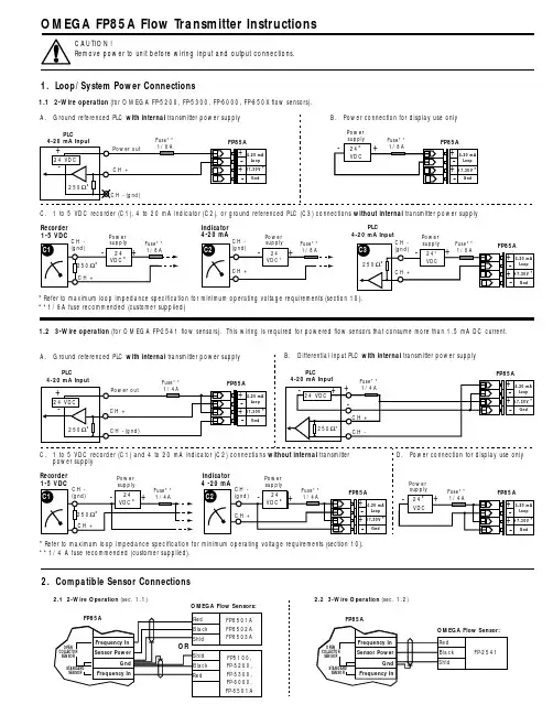
Indicator 4-20 mAC. 1 to 5 VDC recorder (C1), 4 to 20 mA indicator (C2), or ground referenced PLC (C3) connections without internal transmitter power supply *Refer to maximum loop impedance specification for minimum operating voltage requirements (section 10).**1/8A fuse recommended (customer supplied)1.1 2-Wire operation (for OMEGA FP-5200, FP-5300, FP-6000, FP-850X flow sensors). Recorder 1-5 VDCPower *Refer to maximum loop impedance specification for minimum operating voltage requirements (section 10).**1/4 A fuse recommended (customer supplied).1.2 3-Wire operation (for OMEGA FP-2541 flow sensors). This wiring is required for powered flow sensors that consume more than 1.5 mA DC current.Power PLC4-20 mA InputOMEGA FP85A Flow Transmitter InstructionsCAUTION!Remove power to unit before wiring input and output connections.1. Loop/System Power Connections2. Compatible Sensor Connections8. OPTIONS (example)7. CALIBRATE (example)9. Accessories123To return to VIEW:quick pressTo restore original value:quick pressChange:Save:Choose:Press &hold2sContrast FlowTotalizerTotalizerOutputOutputLast calibrationUnit/timebase:h,m,s,dK-factorUnits - label only -4 mA setpoint 20 mA setpointFlow K-factorReturn to VIEW before removing powerPress keys in sequence to continue:A ↓H ↑12To return to VIEW:quick pressTo restore original value:Choose:3Save:Change:quick pressPress keys in sequence to continue:2sPress &holdVIEW=VIEW=Totalizer low= τ=700 ms hi= τ=3 s off= 100 msDisplay avergingFlow displayOutputOutputDecimal postion4 mA adjust 20 mA adjustReturn to VIEW before removing powerA ↓E ↑A.B.C.D.E.F.G.H.A.B.C.D.E.Menu Functions A - H:A.Selects display contrast: 4 levelsB.Sets flow units (gp m) and timebase (gp m ). Flow units label: Aa - Zz, 0 - 9;Timebase options: s=seconds, m=minutes, h=hours, d=days (timebase effects flow display and 4 to 20 mA output)C.Sets flow K-factor: 000.01 to 99999. (see technical notes below)D.Set totalizer units: For label purposes onlyE.Sets totalizer K-factor: 000.01 to 99999. (see technical notes below)F.Sets 4 mA setpoint (4 mA and 20 mA setpoints are reversible)G.Sets 20 mA setpointH.Sets user defined dateTechnical notes:Flow and totalizer K-factors are independent of each other. These K-factors represent the number of pulses generated by the flow sensor for each engineering unit measured (published in flow sensor manual).Menu Functions A - E:A.Selects totalizer reset options: Lock on (enables) or lock off (disables) the VIEW menu totalizer reset security code feature (RST: -- -- -- --).B.Selects display averaging: off = 100ms, low= τ=700ms, hi= τ=3s (also affects 4 to 20 mA output).C.Selects display decimal: **** . to ** .**D.Adjusts 4 mA output: 3.9 to 4.1 mA (overrides 4.00 mA factory calibration)E.Adjusts 20 mA output: 19.8 to 21.0 mA (overrides 20.00 mA factory calibration)O r d e r n o .DescriptionFP85UNM Universal mounting kit, NPT ports FP85UDM Universal mounting kit, DIN portsFP85NM Integral sensor mounting kit, NPT ports FP85DM Integral sensor mounting kit, DIN portsFP8501Integral sensor, 0.5 to 4 inch pipe, Polypropylene body & Titanium rotor pin FP8502Integral sensor, 5 to 8 inch pipe, Polypropylene body & Titanium rotor pin FP8503Integral sensor, 0.5 to 4 inch pipe - PVDF body & Hastelloy C rotor pin FP8501A Integral sensor, 0.5 to 4 inch pipe, Polypropylene body & Titanium rotor pin FP8502A Integral sensor, 5 to 8 inch pipe - Polypropylene body & Titanium rotor pin FP8503A Integral sensor, 0.5 to 4 inch pipe - PVDF body & Hastelloy C rotor pin11. Troubleshooting10. SpecificationsGeneral DataCompatible Sensors:FP-8501, FP-5300, FP-5100, FP-6000, andFP-5200 Series (contact engineering for additional compatible sensors).Display Accuracy:Flow, ±0.1% of readingTotalizers, ±0.03% of reading Enclosure:•Rating:NEMA 4X/IP65•Material:Glass-filled polypropylene •Gasket:Silicone rubber (captive)•Screws:8-32, self-tapping (captive)Display:•Type:8-digit alphanumeric dot matrix •Update rate:Flow=1s, Totalizers=100 mS •Contrast:Variable•Ranges:Flow, 0.01 to 9999.Resettable/permanent totalizers, 0 to 99999999Loop current, 3.90 to 21.00 mAEnvironmentalOperating temperature:-15 to 70 °C (5 to 158 °F)Storage temperature:-15 to 80 °C (5 to 176 °F)Relative humidity:0 to 95%, non-condensingAgency Approvals •CE•Manufactured under ISO 9001Electrical Data Frequency range:0.5 Hz to 500 HzLoop/system power:(2-wire mode) 17 to 30 VDC @ 20 mA max.(3-wire mode) 17 to 30 VDC @ 68 mA max.Sensor power:(2-wiremode)*************.(3-wire mode) 5 VDC @ 20 mA max.Loop:•Impedance: 1 Ω max. @ 17 VDC,300 Ω max. @ 24 VDC,600 Ω max. @ 30 VDC •Accuracy:±0.050 mA •Resolution: 5 µA •Update rate:100 msOutputs:•Current: 4 to 20 mA (adjustable & reversible)•Pulse output:Sensor frequency, optically isolatedopen-collector transistor, max. current sink 10 mA @ 30 VDC(side view)(front view)Dimensions:。

METRAFLEX∣300M, METRAFLEX 300MXBLAC柔性电流传感器适用于万用表和电能质量分析仪3-349-628-034/12.12•应用范围广,3 档量程:3 A/30 A/300 A AC 和高带宽20 Hz ... 100 kHz适用于电能质量分析。
•由于动态量程以及高灵敏度的传感器,甚至低电流也可精确测量。
•低的导体位置影响以及最小化的漏磁影响。
•由于传感器横截面仅有6mm,非常适合在狭小空间内使用。
•甚至戴防护手套时也可安全操作;无论是打开传感器,还是调节量程都可单手操作。
•长时测量时可选用外部电源供电:– MAVOWATT 20/30/230/240/270:DC/DC变压器ISOFLEX-MH XL•电流传感器防护等级IP50,测量放大器防护等级IP40•极高的安全等级 1000 V@CAT III, 600V @ CAT IV,和较强的过载能力。
应用METRAFLEX 300M或METRAFLEX 300MXBL设计用来安全、精准和灵活的测试母线排和配电箱。
线圈在狭小的空间或通道中都可理想使用。
METRAFLEX系列是利用了罗氏原理的交流电流传感器。
连接到合适的仪器上(万用表、数据记录仪、示波器和电能质量分析仪上),便可测试最高可达300A的交流电流。
此柔性电流线圈可以测量难以接近的导体电流。
为此,电流传感器能被放到一个或若干个各种类型和设计的导体上(绝缘线缆,母线排和管线)。
内部电池可让测量放大器单独工作。
柔性电流传感器如需外部电源供电用于长时测量,请参考附件ISO- FLEX-MHXL。
技术参数特征METRAFLEX 300M量程 3 A 30 A 300 A比例因数 1 10 100输出变比1000 mV/A 100 mV/A 10 mV/A 精度(45 ... 65 Hz)±1% 读数± 0.2 A1)±1% 读数±1 A 1)噪音 3 mV eff. 1 mV eff. 0.1 mV eff. 输出接口 1 对 4 mm 带防护的香蕉头特征METRAFLEX 300MXBL量程 3 A 30 A 300 A比例因数 2 20 200输出变比500 mV/A 50 mV/A5 mV/A 精度(45 ... 65 Hz)±1% of读数± 0.1 A1)± 1%读数± 0.5 A1)噪音 1.5 mV eff.输出接口4针电能质量分析仪接头1)标准条件下METRAFLEX 300M电流传感器 /应用万用表GMC-I所有型号电能质量分析仪METRAFLEX 300M ∙METRAFLEX 300MXBL ∙影响量输出负载≥100 kΩ为规定精度频率范围20 Hz 到100 kHz (–20% 衰减)相角误差< ±1° (45 ... 65 Hz)位置精度±2.5%读数外部磁场±0.25%测量范围在距离> 100 mm,从传感器温度系数±0.15%读数/°K标准条件环境温度+15 ︒C ... +25 ︒C相对湿度20% ... 75%工作电压 3 V ±0.5 V被测信号频率45 Hz ... 65 Hz被测量信号波形正弦功率频率磁场< 30 A/m导体位置导体位于线圈中心,并与线圈面垂直;线圈呈圆形输出负载100 kΩ 机械设计测量放大器尺寸110 (H) x 65 (W) x 23 (D) mm输出测量信号METRAFLEX 300M:0.5 m 同轴电缆,4 mm 带防护香蕉头;METRAFLEX 300MXBL:0.5 m同轴电缆,4针电能质量分析仪专用接头。


Magnetic measuring systemOPERATING INSTRUCTIONS MPI-R10MPI-R10-RFModels all rights reserved in accordance with the law. Always mention the source when reproducing our drawings.2ENContents1. Safety Instructions 32. Description32.1 V ersion - MPI-R10-RF43. Installation43.1 Display installation 43.2 Sensor installation 43.3 Magnetic band installation54. Display 55. Key functions 56. System Switching on/off66.1 Switching on the system 66.2 Switching off the system67. Operating mode 67.1 Absolute/incremental measuring mode selection 67.2 Unit of measure selection 67.3 Origin setting67.4 Absolute reference setting 67.5 Direct programming of the absolute reference value and compensation value 77.6 Targets7 7.6.1Reaching the target position 7 7.6.2 Target display mode 7 7.6.3 Target tolerance 87.7 Angular Measurement87.8 Version - MPI-R10-RF 87.8.1 Programming of the network parameter (nEt id) and thechannel parameter (nEt ch) 8 7.8.2 Targets88. Programming mode 8 8.1 Programming of parameters with numeric values8 8.2 Device parameters (in alphabetical order) 8 8.3 Main menu tree 9 8.4 Target menu tree9 8.5 Additional features10 8.5.1 Reset 10 8.5.2 Calibration 10 8.5.3 LCD test10 8.5.4 Correction coefficients10 8.5.5 Revision109. Battery replacement 1010. Display messages and troubleshooting 10Models all rights reserved in accordance with the law. Always mention the source when reproducing our drawings.3EN1. Safety InstructionsThe product has been designed and manufactured in ac-cordance with the current regulations. The product leaves the factory ready for use and complies with the safety stand-ards. To maintain the product in this state, it is necessary that it is assembled and used properly , in the closest compliance with this instructions manual and with the following specific safety precautions.Before installing and using the MPI-R10, read carefully this manual, which is intended as an indispensable supplement to the existing documentation (catalogues, data sheets).Morever , all the rules of law must be observed, in regard to accident prevention and environmental protection.The use, without complying with the descriptions / specific parameters, (in combination with systems / machines / processes to be controlled), can lead to a malfunction of the product, causing:- health hazards,- environmental hazards,- damage to the product and to its proper functionality .The device must not be used : - in explosion hazard areas;- in medical/life support areas and equipment.Do not open the equipment and do not tamper with it! Any tampering might have a negative impact on reliability of the device and might be dangerous. Do not attempt any repair . Return any defective equipment to the manufacturer! Any violation of the integrity of the device as delivered will cause the warranty loss.Changes or modifications, not expressly approved by the party responsible for compliance, could void the user’s authority to operate the equipment.Setup/CommissioningIn case of any malfunction (even in case of change in operating conditions), the device must be switched off immediately . Switch off power supply during any installation work on the equipment. Installation and commissioning are allowed by trained and authorised staff only . After correct setup and commissioning, the device is ready for operation. Maintenance/repairSwitch off the power supply of the equipment before any action. Maintenance should be performed by trained and authorised staff only .NOTE: This equipment has been tested and found to comply with the limits for a Class A digital device, pursuant to part 15 of the FCC Rules. These limits are designed to provide reasonable protection against harmful interference when the equipment is operating in a commercial environment. This equipment generates, uses, and can radiate radio frequency energy: if not installed and used in accordance with the instructions manual, it may cause harmful interference to radio communications. Operation of this equipment in a residential area is likely to causeharmful interference in which case the user will be required to correct the interference at his own expense.2. DescriptionConnected to the dedicated sensor FC-MPI, and combined with the Elesa magnetic band M-BAND-10, the MPI-R10 is a complete system for the measurement of linear and angular displacement. Characterised by extremely easy assembly , it allows precise alignment and positioning, reducing time and machining procedures to a minimum.MPI-R10 main features are:- Multifunction LCD with 4 function keys.- Absolute/ incremental mode.- Programmable offset and targets function.- Lithium battery powered.- Protection against accidental polarity inversion.The sensor cable F C-MPI is made of a metallic enclosure containing the electronic sensor , a multipolar flexible cable and a connector to be plugged into the MPI-R10.The sensor cable is available in different lengths.The magnetic band M-BAND-10 is made of two separate parts: the magnetic band and the cover strip. The magnetic band is made of a magnetic tape, a carrier strip and an adhesive tape (Fig. 2).The cover strip is made of a protection strip and an adhesivetape (Fig. 1).(1) The reading speed influences the battery life.(2) Resolution: the smallest change in length that the system is capable ofdisplaying.(3) Precision: the maximum deviation of the value measured by thesystem from the actual one.(4) Repeat accuracy: the degree of closeness among a series of meas-MPI-R10FC-MPI2.1. Version – MPI-R10-RFThe MPI-R10-RF is compatible with Elesa wireless networkthat allows magnetic measuring system and indicators tocommunicate via radio with a PLC.Elesa wireless network is made by the following components:- One control unit UC-RF- Max 36 electronic position indicators or magnetic measuring.The control unit UC-RF is provided with a standard interfacefor the most common industrial busses to be connectedto the PLC and allows the transmission of the informationbetween the PLC and the MPI-R10-RF magnetic measuringsystem. The UC-RF exchanges information with the MPI-R10-RF via radio frequency and allows the setting of the targetposition and the control of the current position of eachindicator, directly from the PLC.2. Remove all drilling burrs before fitting the MPI-R10.3. Fit the lower part of the case into the housing.4. Press onto the upper part until the case is completelysnapped in.3.2. Sensor installationFix the magnetic sensor by using M3 screws (not included inthe supply). During the installation, use a spacer (max 1 mmis suggested) to grant the parallelism between the sensorand the magnetic band.Models all rights reserved in accordance with the law. Always mention the source when reproducing our drawings.5EN4. Display1. Absolute or relative mode indicator2. Low battery level indicator3. mm, INCH or degree unit of measure4. Target position indication5. RF connection indicator5. Key functionsThe function of the key changes depending on the mode of the device.12354The maximum distance between the sensor and the magnetic band, to ensure a correct reading of the displacement, is 1mm.3.3. Magnetic band installationTo mount the magnetic band follow the instructions below: - Clean the mounting surface carefully .- Remove the protective film from the adhesive tape of the magnetic band.- Stick the magnetic band on the mounting surface. - Clean the surface of the magnetic band carefully .- Remove the protective film from the adhesive tape of the cover strip.- Stick the cover strip on the magnetic band. The cover strip must be put on the magnetic band to protect it from possible mechanical damages.- In case of absence of a seat for the housing of M-BAND-10, secure the ends of the cover strip to prevent unintentional peeling.The mounting surface must be flat. Buckles or bumps will lead to measuring inaccuracies. To guarantee an optimal adhesion of the adhesive tapes, the mounting surfaces must be perfectly cleaned, dry and smooth. The following surface roughness is recommended: Ra <= 3,2 N8 (Rz <= 25). To maximize the adhesion install the strip applying pressure. Gluing should preferably be carried out at temperatures between 20 °C to 30 °C and in dry atmosphere.WARNINGOnce the installation is completed, the calibration procedure must be carried out as shown in cap. 8.5.2.Models all rights reserved in accordance with the law. Always mention the source when reproducing our drawings.6EN7. Operating mode7.1. Absolute/incremental measuring mode selectionto select the absolute or incremental measuring mode.The measuring mode selected is shown on the display by the symbols:- ABS: absolute measuring mode.- REL function by the menu voice __0____ (see chap.8.3).The available options are:- ArCLr (default): when relative measurement is selected, the value is always reset to zero.- Ar : passing fromABS to REL , the relative measurement is not reset to zero.- OFFTo program the parameters listed above, see chap. 8.3.7.2.The options available are millimeters, inches and degrees.The measuring mode selected is shown on the display by the symbols: mm for millimeters, inch for inches and with the ° suffix for degrees.function by the menu voice 0______.The available options are:- ALL (default): units of measure that can be selected: mm, inch, degree.- nodEG : units of measure that can be selected: mm, inch.- OFF : the key is disabled and does not allow changing the selected measuring mode.To program the parameters listed above, see chap. 8.37.3. for three seconds to set the origin of the Keeping pressed the ORG to confirm or another key to cancel.Confirming the setting of the origin, the display will be reset to zero: this position of the sensor must be considered as the origin of the following measurements.7.4. Setting the absolute referenceAfter having selected the absolute measuring mode and to the sum of the values of the parameters Origin (absolute value of reference) and the selected OFFS (compensation value).The value of compensation (OFFSET ) allows you to adjust the value shown on the display in such a way that takes into account,6. System Switching on/off6.1. Switching on the systemAfter you have read the section “Safety Instructions”, proceed by switching on the indicator .- - The display will light up and the indicator is ready to be used.6.2. Switching off the system To switch the system off :- enter the programming mode, - (see chap. 8.3)- - - The display will turn off and the indicator will go into low power mode.Models all rights reserved in accordance with the law. Always mention the source when reproducing our drawings.7ENfor example, wear or tool change. The system allows you to store up to 10 values of compensation.+display the last compensation value used (eg OFS 0).to confirm.The screen will display the absolute value equal to the sum of the values of the parameters Origin and OFFSet .To program the offset values, see parameterOFFSetof cap. 8.3.in the menu voice __0___0 The available options are:LOAd_OrG : the key combinations allow to choose an offset OFFFor programming the parameters listed above see paragraph 8.37.5. Direct programming of the absolute reference value +can be programmed to allow direct access to the programming of the OrIGIn or OFFSEt parameters.It is possible to change the function of the keys combination choosing one of the available options in the menu voice 0_____0.The available options are:- PrOGOrG : direct programming of the absolute reference value (OrIGIn parameter).- PrOGOFS : direct programming of the compensation value (OFFSEt parameter).- OFF : the keys combination is not associated to any function in the operating mode.7.6 TargetsMPI-R10 allows to set up to 32 target positions to store relevant machine configuration setting.To program the targets:- select tArGEtS in the main menu (see cap 8.3).- select PrOG_TG (see chap. 8.4).- select the required memory location (PtrG 01 to PtrG 32).- - Follow the instructions in cap. 8.1 to set the required value.To load a target:- select tArGEtS in the main menu (see cap 8.3).- select LOAd_TG (see chap. 8.4).-LtrG 01 to LtrG 32)-- The value of the selected target is shown.programming or loading of targets depending on the value assigned to parameter___0_0.If enabled, the key combination allows to choose between the two following operations:- LOAd_tG - PrOG_tGIt is possible to change the function of the keys combination choosing one of the available options in the menu voice ___0_0.The available options are:- tArGet : enable the direct load or program targets functions.- OFF 7.6.1. Reaching the target positionWhen a target is selected by the PLC (RF version MPI-R10-sensor to reach the target by means of the symbols It is possible to set the FLIP_tG parameter (see chap. 8.2) to adapt the target position indication to the actual sensor configuration.It is possible to set the tolerance of the target as absolute difference from the set value by means of the P_tOLL parameter (see chap. 8.2).The target position indicators will work, depending from the FLIP_tG and P_tOLL parameters, as in the following table.T = set target M = measured valueToll = tolerance (see P_toll )S t O P_t G depending on the settings of the device.Models all rights reserved in accordance with the law. Always mention the source when reproducing our drawings.8ENIt is possible to change the function of the key and the target mode choosing one of the available options in the menu voice ____0__.The available options are:- d_tArG (default): when a target is loaded, the display shows the actual absolute position and the indication to- : when a target is loaded, the display showsthe distance to the set target and the indication to reach thedisplay shows the actual absolute position.7.6.3. Target toleranceSet the value of P_toll parameter to define the tollerance allowed for target (see chap. 8.2 for details).7.7. A ngular measurementMPI-R10 allows to measure angular displacements. To obtain the correct measurement, it is needed to set the parameter “Radius” with the measure of the radius of the arc where the magnetic band is placed.7.8. Version - MPI-R10-RF7.8.1. Programming the network parameter (nEt id) and the channel parameter (nEt ch)The system radio network is defined by the following two parameters:- nEt id: id 00/99- nEt ch: ch 01/36These parameters can be configured in the Radio menu of the indicator (see chap. 8.3) and must be set according to the PLC recipe to guarantee a perfect communication between UC-RF and MPI-R10-RF .WarningFor MPI-R10-RF with firmware release equal to 5.1 or higher , channel 1 is equivalent to channel 4 of the previous version. Consider it when used in old system with UC-RF with firmware release lower than 5.1.7.8.2 TargetsUsing MPI-R10-RF , target positions can be sent from the PLCto the indicators through the control unit. When a target is set, the behaviour is the same as decribed in cap 7.6.for 3 seconds to enter the programming mode. Depending on the setting of PASS parameter (seeandto exit the programming mode. The programming mode is automatically dropped after 30 seconds of inactivity .of parameters.When a parameter is changed from its stored value, by confirming it, the display will show the message CHAnGEd .When exiting from the programming mode, the parameter are stored in the internal memory . If a parameter was changed, the display will show the message StorEd .8.2. Device parameters (in alphabetical order)Models all rights reserved in accordance with the law. Always mention the source when reproducing our drawings.9EN8.3. M ain menu treeSPEEd 1 ÷ SPEEd 5If mm: 1, 0.1,0.01If inch 1, 0.1, 0.01, 0.0010.000001÷9.9999990.000001÷9.999999Radius dEG_rES0.01÷9999.991, 0.1, 0.018.4. T arget menu treePtrG 01…PtrG 32LtrG 01LtrG 32…I f m m -9999.99÷9999.99I f i n c h -9999.99÷9999.99I f D e g -99999÷99999The parameter value depends on the unit of measure and resolution set .The symbols on the display related to the target feature are used .See chap. 5Models all rights reserved in accordance with the law. Always mention the source when reproducing our drawings.10EN8.5. Additional features8.5.1. ResetTo reset the device to its factory setup:- select the voice RESEt- select YES- 8.5.2. Calibration The Calibration voice in the main menu activates the CALIBRATION MODE and the display shows GO .At this point, the user must slowly move the sensor in one direction along the magnetic band.After the GO , a progress bar is displayed that will grow as long the sensor is moved. The procedure is completed when the measurement position is shown again by the display .This operation allows the sensor to be accurately bound to the magnetic tape and has to be done every time after the installation of the sensor .8.5.3. Test LCDThe LcdtESt voice in the main menu allows to switch on all the display segments.8.5.4. Correction coefficients To improve the correctness of the measurement, MPI-R10 allows to set two correction factors that take into accountthe differencies between ideal and actual installation of the magnetic band:- LinCorr : is the ratio between the actual measurement and the value measured by the device in linear measurement.- AngCorr : is the ratio between the actual measurement and the value measured by the device in angular measurement.To calculate the correction factor , set it to 1 then read the value measured (M) in a reference point (K). The correction factor will be equal to K/M.Verify that the measurement done in the reference point and/or other known points is correct.8.5.5. RevisionThe release data of the device are shown, starting with the r letter case of support needed.9. Battery replacementThe internal lithium 1/2 AA - 3.6 V battery ensures over 3 years battery life (RF version - 2 years).The symbol is shown on the display when the battery replacement is required.The replacement is made by simply removing the cover onthe back.By replacing the battery in less than 5 seconds, all the measurements and settings wil not be lost. If more time is required and the display turns off, the settings of the device have to be set or verified again.10. Display messages and troubleshotingModels all rights reserved in accordance with the law. Always mention the source when reproducing our drawings.11ENEU DECLARATION OF CONFORMITY (DoC)COMPANY NAME: Elesa S.p.a.POSTAL ADDRESS: Via Pompei 29POSTCODE AND CITY: 20900 Monza TELEPHONE NUMBER: +39 039 28111E-MAIL ADDRESS: **************Declare that the DoC is issued under our sole responsibility and belongs to the following product:PRODUCT: Magnetic measuring system APPARATUS MODEL: MPI-R10TRADE MARK: Elesa The object of the Declaration described above is in conformity with the relevant Union harmonization legislation:2014/30/EU (EMC): Electromagnetic Compatibility Directive 2011/65/UE (RoHS): Restriction of the use of certain Hazardous Substances in electrical and electronic equipment The following harmonized standards and technical specifications have been applied:EN 61326-1:2013Notified Body:Not Involved (Annex II - Conformity Assessment Module A)Additional information:Software Version: 5.1 or higherPLACE, DATE OF ISSUE: CARLO BERTANI Monza – Italy MANAGING DIRECTOR 17/05/2021 GENERAL MANAGEREU DECLARATION OF CONFORMITY (DoC)COMPANY NAME: Elesa S.p.a.POSTAL ADDRESS: Via Pompei 29POSTCODE AND CITY: 20900 Monza TELEPHONE NUMBER: +39 039 28111E-MAIL ADDRESS: **************Declare that the DoC is issued under our sole responsibility and belongs to the following product:PRODUCT: Magnetic measuring system APPARATUS MODEL: MPI-R10-RF TRADE MARK: Elesa The object of the Declaration described above is in conformity with the relevant Union harmonization legislation:2014/53/EU (RED) Radio Equipment Directive2011/65/UE (RoHS): Restriction of the use of certain Hazardous Substances in electrical and electronic equipment The following harmonized standards and technical specifications have been applied:EN 62311:2008EN 61010-1:2010ETSI EN 301 489-1 V2.1.1ETSI EN 301 489-1 V2.2.3ETSI EN 301 489-17 V3.1.1Draft ETSI EN 301 489-17 v3.2.2EN 61326-1:2013ETSI EN 300 328 V2.2.2Notified Body:Not Involved (Annex II - Conformity Assessment Module A)Additional information:Software Version: 5.1 or higherPLACE, DATE OF ISSUE: CARLO BERTANI Monza – Italy MANAGING DIRECTOR 17/05/2021 GENERAL MANAGERModels all rights reserved in accordance with the law. Always mention the source when reproducing our drawings.12ENELESA S.p.A.Via Pompei, 2920900 Monza (MB) Italy phone +39 039 28111**************Elesa S.p.A., Monza, May 2021The texts and examples have been written with great care, nonetheless, mistakes can always happen.The Company Elesa S.p.A. can neither be held legally responsible nor liable for lacking or incorrect information and the ensuing consequences.The Company Elesa S.p.A. reserves the right to alter or improve the magnetic measuring system or parts of them without prior notice.© C O P Y R I G H T E L E S A 2021A r t . N r . Z D O I U -M P I R 10-E N -R。

LevelPressureFlowTemperatureLiquid AnalysisRegistrationSystem ComponentsServicesSolutions电磁流量测量系统 Proline Promag 50/53 W适用于水和污水行业中的流量测量应用可用于测量电导率≥5 μS/cm的流体测量 饮用水 污水 废水污泥 流量可达110000m /h 流体温度可达80℃ 过程压力可达40bar 装配长度符合DVGW/ISO标准 专用内衬材料 聚胺酯衬里适用于测量冷水和有轻微磨损的流体 硬橡胶衬里适用于所有水的测量场合(特别适用于 饮用水) 防爆认证: ATEX, FM, CSA, NEPSI 饮用水行业认证: KTW,WRAS,NSF,ACS3可以和多种过程控制系统相连的通信接口: 标准HART接口 Promag 50: PROFIBUS-PA Promag 53: PROFIBUS-PA/-DP,FF优点电磁流量测量系统提供经济高效的流量测量,测量精度 高,测量范围广. Proline变送器包括: 模块化的结构和操作理念提高工作效率 电极清洗软件可选 统一的操作方式 Promag传感器: 无压损 对振动不敏感 安装和调试简单TI 046D/28/zh/08.07Pro line Promag 5 0/53 W功能及系统设计测量原理法拉第电磁感应定律证明一个导体在磁场中运动将感应生成一个电势.采用电磁测量原理, 流体就 是运动中的导体.感应电势相对于流速成正比并被两个测量电极所检测,然后变送器将它进行放 大. 根据管道横截面积计算出体积流量.恒定的磁场由极性交替变化的开关直流电流所产生.Ue = BL v Q = A v Ue =感应电势 B = 磁场强度 L = 电极距离 v = 流速 Q =体积流量 A = 管道横截面 I = 电流强度测量系统测量系统由一台变送器和一台传感器组成. 有两种型号可选: 一体化型: 变送器和传感器组成一个整体的机械单元. 分离型 : 变送器和传感器被分开安装. 变送器: Promag 50 (按键操作, 两行背光显示 ) Promag 53 (光敏键操作 , 无须打开外壳, 四行背光显示) 传感器: Promag W (DN 25...2000)2Endress + HauserPro line Promag 5 0/53 W输入变量测量变量 测量范围 量程比 输入信号流速(与感应电势成正比) v=0.01...10m/s ,指定测量精度 >1000:1 状态输入: U=3...30V DC,Ri=5kΩ,电气隔离 可设置为:累积量复位,测量值抑制,故障信息复位 状态输入,带 PROFIBUS DP和 MODBUS RS 485: U=3…30 VDC,Ri=3kΩ, 电气隔离 开关级别:3… 30VDC,与极性无关 可设置为:累积量复位,测量值抑制,故障信息复位,批量开始 /停止(可选),批量累积复位 (可选) 电流输入(仅指Promag 53): 有源 /无源可选,电气隔离,满量程值可选,分辨率:3 μA, 温度系数:0.005% o.r./ ℃( o.r.= 读数的) 有源:4...20mA,Ri≤150Ω,Uout=24 VDC, 抗电流短路 无源:0/4...20mA,Ri≤ 150 Ω, Umax=30 VDC输出变量输出信号Promag 50 电流输出: 有源 /无源可选,电气隔离,时间常数可选(0.01...100s),满量程值可选, 温度系数:0.005% o.r. / ℃,分辨率:0.5 μA 有源: 0/4...20mA,R L<700Ω(HART :RL≥250Ω ) 无源: 4...20mA,操作电压Vs 18...30 VDC, Ri≤150Ω 脉冲 /频率输出: 无源,集电极开路,30 VDC ,250mA ,电气隔离 频率输出:满量程频率2...1000Hz(fmax=1250Hz),开关比1:1, max.10s 脉冲输出:脉冲值和脉冲极性可选,最大脉冲宽度可设定 (0.5...2000m s) PROFIBUS-DP接口: 传输技术(物理层):RS485,符合 ANSI/TIA/EIA-485-A: 1998,电气隔离 简介V3.0 数据传输速率: 9.6 kBaud...12MBaud 自动数字传输速率识别 功能块:1x 模拟量输入, 3x累积量 输出:体积流量,累积量 输入:强制归零(开 /关),累积量控制,现场显示值 循环数据传输与"Promag33"一致 总线地址通过流量计上的微型开关或现场显示(可选)调整Endress + Hauser3Pro line Promag 5 0/53 WPROFIBUS-PA接口: 传输技术(物理层):RS 485,符合ANSI/TIA/EIA-485-A: 1998,电气隔离 简介V3.0 数据传输速率: 9.6 k Baud...12 MBaud 自动数据传输速度识别 功能块:1×模拟量输入, 1×累积量 输出:体积流量,累积量 输入:强制归零(开 /关),累积量控制,现场显示值 循环数据传输与"Promag33"一致 总线地址通过流量计上的微型开关或现场显示(可选)调整 Promag 53 电流输出: 有源 /无源可选,电气隔离,时间常数可选(0.01...100s ),满量程值可选, 温度系数:0.005% o.r./ ℃,分辨率:0.5 μA 有源: 0/4...20mA,R L<700Ω (HART: RL≥250Ω ) 无源: 4...20mA, 操作电压 Vs 18...30 VDC,Ri≤ 150 Ω 脉冲 /频率输出: 有源 /无源可选,电气隔离( Exi型:无源) 有源: 24 VDC, 25mA (max.250mA/20ms) R L>100Ω 无源:集电极开路, 30 VDC, 250mA 频率输出:满量程频率2...10000Hz(fmax=12500Hz) ,EEx-ia: 2...5000Hz; 开关比 1:1,脉冲宽度 max.10s 脉冲输出:脉冲值和脉冲极性可选,脉冲宽度可设定(0.05...2000ms) PROFIBUS-DP接口: 传输技术(物理层):RS485,符合 ANSI/TIA/EIA-485-A: 1998,电气隔离 简介V3.0 数据传输速率: 9.6 kBaud...12MBaud 自动数字传输速率识别 功能块:2x 模拟量输入, 3x累积量 输出:体积流量,计算质量流量,累积量1...3 输入:强制归零(开 /关),累积量控制,现场显示值 循环数据传输与"Promag33"一致 总线地址通过流量计上的微型开关或现场显示(可选)调整 输出组合见第7页PROFIBUS-PA接口: 传输技术(物理层):IEC 61158-2 (MBP),电气隔离 简介V3.0 电流消耗: 11mA 允许电源电压: 9...32V 总线连接,内置极性反向保护 故障电流FDE:0mA 功能块:2x 模拟量输入, 3x累积量 输出:体积流量,计算质量流量,累积量1...3 输入:强制归零(开 /关),累积量控制,现场显示值 循环数据传输与"Promag33"一致 总线地址通过流量计上的微型开关或现场显示(可选)调整 4 Endress + HauserPro line Promag 5 0/53 WFF基金会现场总线接口: FF 基金会现场总线 H1 传输技术(物理层):IEC61158-2 (MBP),电气隔离 ITK V4.01 电流消耗: 12mA 故障电流FDE:0mA 总线连接,内置极性反向保护 功能块:5x 模拟量输入, 1x离散输出, 1xPID 输出:体积流量,计算质量流量,累积量1...3 输入:强制归零(开 /关),累积量复位 支持主机连接功能 MODBUS接口: 传输技术(物理层):RS 485符合ANSI/TIA/EIA-485-A:1998,电气隔离 MODBUS设备类型:从动设备 地址范围1… 247 总线地址通过流量计上的微型开关或现场显示(可选)调整 支持MODBUS功能代码: 03, 04, 06, 08, 16, 23 Broadcast: 功能代码 06, 16, 23 传输模式: RTU或ASC II 支持波特率:1200, 2400 ,4800, 9600 ,19200,38400, 57600, 115200 Baud 响应时间 直接数据访问=25…50ms 自动扫描缓冲器(数据范围)=3… 5ms 输出组合见第7页报警信号电源输出→故障响应可选(如遵循 NAMUR建议NE43) 脉冲/频率输出→故障响应可选 状态输出( Promag 50 )→故障或电源故障时断开 继电器输出(Promag 53)→故障或电源故障时处于失电状态负载 开关输出参见"输出信号". 状态输出(Promag 50, Promag 53) 集电极开路, max. 30 VDC/ 250mA,电气隔离 可设置为:故障信息,空管检测(EPD),流向,限位值 继电器输出( Promag 53) 常闭(NC )或常开(NO)触点可选 (默认值:继电器 1=NO ,继电器 2=NC) max.30V/0.5A AC;60V/0.1A DC ,电气隔离 可设置为:故障信息,空管检测(EPD),流向,限位值,批量控制触点小流量切除 电气隔离小流量切除开关点可选 所有输入,输出和供电回路相互电气隔离Endress + Hauser5Pro line Promag 5 0/53 W供电电气连接 测量单元变送器连接,电缆截面积: max. 2.5 mm A:图A (现场变送器外壳) B:图B (不锈钢现场变送器外壳) C:图C (墙装式变送器外壳) *)不可更换通信板 ** )可更换通信板2a.接线腔盖 b.供电电缆:85...260VAC, 20...55VAC,16...62VDC 端子No.1:L1对AC ,L+对 DC 端子No.2:N对 AC, L-对DC c.电源线接地端子 d.信号电缆:见端子分配表→ 第7页 总线电缆: 端子 NO.26: DP(A)/PA(+)/FF(+)/MODBUS RS485(A)/(PA,FF:带极性反向保护) 端子 NO.27: DP(B)/PA(-)/FF(-)/MODBUS RS485(B)/(PA,FF:带极性反向保护) e.信号电缆屏蔽层/总线电缆 /RS485 接地端 f.FXA 193接口(Fieldcheck,Tof Tool-Fieldtool Package) g.信号电缆:见端子分配表→ 第7页 外部终端电缆(仅指 PROFIBUS-DP,带固定分配通信板) 端子 NO.24:+ 5V 端子 NO.25: DGND6Endress + HauserPro line Promag 5 0/53 WPromag 50端子分配选型代码 50***-***********W 50***-***********A 50***-***********D 50***-***********H 50***-***********J 50***-***********S 50***-***********T 接地,电源—见第6页 状态输入 端子号(输入/输出)20(+)/21(-) 22(+)/23( -) 24(+)/25(-) 26(+)/27(-)状态输出 -频率输出 频率输出 +5V (外部终端) 频率输出 Exi,无源 频率输出 Exi,无源电流输出 HART 电流输出 HART 电流输出 HART PROFIBUS PA PROFIBUS DP 电流输出Exi, 有源,HART 电流输出Exi, 无源,HARTPromag 53端子分配 根据 不同 的订货要求,通信 板上 的输 出和输入端子分配既可以是固 定的 ,也可以是可变的 (见 表),需要更换模块时,可作为附件订货.选型代码 端子分配固定 53***-***********A 53***-***********B 53***-***********F 53***-***********G 53***-***********H 53***-***********J 53***-***********K 53***-***********Q 53***-***********S 53***-***********T 端子分配可变 53***-***********C 53***-***********D 53***-***********L 53***-***********M 53***-***********N 53***-***********P 53***-***********V 53***-***********2 53***-***********4 53***-***********7 继电器输出2 继电器输出2 状态输入 状态输入 状态输入 电流输出 电流输出 继电器输出2 继电器输出 电流输入 继电器输出2 继电器输出1 继电器输出1 继电器输出 继电器输出2 频率输出 频率输出 频率输出 继电器输出1 电流输出 继电器输出 继电器输出1 频率输出 频率输出 状态输入频率输出 Exi 频率输出 Exi 电流输出 HART 电流输出 HART PROFIBUS-PA Ex i FF现场总线, Exi PROFIBUS-PA PROFIBUS-DP FF现场总线 MODBUS RS 485 电流输出Exi 有源,HART 电流输出Exi 无源,HART 电流输出 HART 电流输出 HART 电流输出 HART 电流输出 HART MODBUS RS 485 PROFIBUS-DP PROFIBUS-DP 电流输出 HART 电流输出 HART MODBUS RS 485端子号(输入/输出)20(+)/21(-) 22(+)/23( -) 24(+)/25(-) 26(+)/27(-)频率输出 频率输出 继电器输出1 频率输出 状态输入 状态输入 状态输入 频率输出 频率输出 状态输入Endress + Hauser7Pro line Promag 5 0/53 W电气连接 分离型电极回路 EPD空管检测线圈回路n.c.=电缆屏蔽层悬空电缆入口电源和信号电缆(输入 /输出): 电缆入口M20 x 1.5( 8...12mm) 传感器铠装电缆入口M20×1.5( 9.5...16mm) 螺纹电缆入口1/2〃 NPT,G1/2〃 分离型连接电缆: 电缆入口M20 ×1.5(8...12mm) 传感器铠装电缆入口M20×1.5(9.5...16mm ) 螺纹电缆入口1/2〃 NPT,G1/2〃8Endress + HauserPro line Promag 5 0/53 W分离 型电 缆规格线圈电缆: 2 2× 0.75mm PVC 电缆带普通铜网屏蔽层(≈Φ7mm) 电阻:≤37 Ω/km 电容:芯/芯,屏蔽层接地:≤ 120pF/m 恒定操作温度: -20...+80℃ 电缆截面积:max.2.5mm2信号电缆: 2 3× 0.38mm PVC 电缆带普通铜网屏蔽层(≈Φ7mm)和分屏层 空管检测(EPD): 4×0.38mm PVC电缆带普通铜网屏蔽层(≈Φ 7mm )和分屏层 电阻:≤50 Ω/km 电容:芯/屏蔽层:≤ 420pF/m 恒定操作温度: -20...+80℃ 电缆截面积:max.2.5mm2 2A=信号电缆, b=线圈电缆(截面积: max.2.5mm 2) 1=芯, 2=芯绝缘层, 3=芯屏蔽层, 4=芯护套,5=芯加固层,6=电缆屏蔽层, 7=电缆护套E+H可提供增强型连接电缆,以下情况推荐使用该电缆 埋地电缆 可能有动物啃咬的场合 IP68 仪表用 在有强烈电子干扰的区域内: 根据通用安全要求,测量管应遵循EN61010 ,EN61326/A1规定的EMC要求及 NAMUR建议NE21 注意! 将壳体内的接地端子接地,应使裸露电缆长度尽可能短Endress + Hauser9Pro line Promag 5 0/53 W电源85...260 V AC,45...65Hz 20...55 V AC,45...65Hz 16...62 V DC PROFIBUS-PA 和FF 现场总线, Non-Ex:9...32V DC Ex i:9...24V DC Ex d:9...32V DC功率消耗AC:<15VA(包括传感器) DC:<15W(包括传感器) 启动电流: max.13.5A(<50ms)24VDC max.3A(<5ms)260VAC电源故障 接地EEPROM或T-DAT (仅指 Promag 53)电源故障时,贮存测量值和设置的参数 S-DAT =存有传感器参数的可交换数据存储器:公称直径,序列号,标定因子,零点等. 标准 为了保证测量精度,避免电极的腐蚀损坏,传感器和介质必须有相同的电势.等电势通过在传感 器内安装参考电极来实现. 如果介质在无衬里并接地的金属管中流动,只要将变送器外壳接地,就能满足接地要求.对于分 离型的接地也是一样. 提示! 如果不能确定介质的正确接地与否,应安装接地环.TMTM注意:对于不带参考电极或无金属接线端的传感器,必须按照以下指南实现电势匹配,这些特殊的措施 尤其适用于无法确保标准接地以及可能会产生强匹配电流的场合.10Endress + Hauser带内衬的管道(阴极保护)介质不能被接地,测量管必须按下述方式接地:保证前后管段之间有电气连接(铜线)。
带有系统分析功能的多参数电量表SINEAX A210, A220, A230s, A230带有系统分析的多功能电能监控单元SINEAX A210和A220合理和经济的测量48个被测参数,8个能耗值显示,平均和最大/最小值功能。
电气系统可以在所有四个象限中进行全面评估。
显示单元被测物通过高对比度,14 毫米高,可调光的LED进行显示,该LED带有3位数字和符号(电度表为8位数字,频率为4位数字)。
计量集成式电度表记录有功电能(进/出)和无功电能(感应/电容)。
如果使用扩展模块的数字输入来切换费率,则活动仪表的数量将增加一倍。
输出有 2 个 S0 输出可用于控制继电器。
可以输出能量脉冲,也可以输出可编程极限的状态。
SINEAX A230s和A230多功能准确的测量134个测量值,8个能耗值显示,综合平均值和最大值/最小值值函数,THD和谐波分析,不对称电压和零位移电压。
所有这些被测量构成了对所有四个象限中电气系统进行综合分析和评估的基础。
显示单元被测物通过高对比度,14毫米高,可调光的LED进行显示,并带有4位数字和符号(电度表为8位数字)。
在用户模式下,不需要的被测物可以被抑制。
LOOP模式依次显示2到10个可编程显示器。
分析趋势分析可用于所有平均值。
谐波含量和系统不对称性的计算为操作员提供了有关系统状态的重要信息。
A210A220A230s A230正面尺寸96 x 96毫米144 x 144毫米96 x 96毫米144 x 144毫米连接方式单相,3/4线平衡,3/4线不平衡输入LL: 0 – 500 V, LN: 0 – 290 V, F: 45 – 65 Hz, I: 0 – 1/5A精度U, I: 0,5%;P,Q,S,meters:1%U, I: 0,2%;P,Q,S,meters:0,5%14mm显示3位数字+符号4位数字+符号,可编程电源输出100 – 230 V AC / DC或24 – 60 V AC / DC 2个数字量输出作为脉冲或限值输出被测量85266能量计88平均值5个P,Q和S平均值各种功能THD没有谐波分析没有是15次电压不平衡没有是连接弹簧夹或螺丝夹端子防护等级(前面板)IP66扩展模块扩展了 A210,A220,A230s 和 A230 的功能它们可以简单地卡在基本仪器的背面并从其获取电源。

3-349-821-035/6.17GMC-I Messtechnik GmbHMETR ISO PRIME+Digital High-Voltage Insulation TesterGermanAccreditation Body D-K-15080-01-01FeaturesTest Voltages to 5000VThe instrument is suitable for non-destructive measurement of insulation resistance in electrical systems, as well as in machines, transformers, cables and electrical equipment utilized in, for example, locomotives, street cars and ocean going vessels with selectable test voltages of up to 5kV.Voltage Measurement to 1000VTesting for absence of voltage at the device under test in systems of up to 1kV can be performed with the voltage measuring range.Discharging Capacitive Devices Under TestCapacitive devices under test such as cables and coils, which may be charged by the test voltage, are discharged by the mea-suring instrument. The falling voltage value can be observed at the display.Measurements per EN 61557 Parts 1 and 2 (VDE 0413)Nominal current amounts to 1mA at a test voltage of 100V, 250V, 500V or 1000V.Highly Insulated Measurement CablesThe highly insulated measurement cables are permanently con-nected for safety reasons, and due to technical measuring con-siderations. Danger resulting from inadvertently disconnected cables, for example in the event of charging caused by capacitive devices under test, is thus avoided.Polarization IndexA polarization index test is recommended for electrical machines. This procedure involves expanded testing of insulation resistance. DC measuring voltage from the METRISO PRIME+ is applied to the insulation for a duration of 10 minutes. Measured values are documented after one minute, and after ten minutes. If the insula-tion is good, the value measured after ten minutes is higher than the value measured after one minute. The relationship between the two measurement values is the polarization index. Charged material within the insulation is aligned due to the application of measuring voltage over a long period of time, resulting in polariza-tion. The polarization index indicates whether or not the charged material contained in the insulation can still be moved, thus allow-ing for polarization. This, in turn, is an indication of the condition of the insulation.Data Management and Report GenerationThe data of each measurement can be stored under a selected object number. Furthermore, a description for this object can be entered via the keyboard of the optional PSI module (Feature I1).The data management function allows for individual measurement data of a previously selected object to be displayed and to be deleted if required, or for previously entered objects to be deleted.Depending on the number of stored objects (max. 254), up to 1,600 measurements can be stored. The current memory occu-pancy is continuously displayed as a bar graph.Report data can be printed out at an external printer with Cen-tronics interface via PSI module (Feature I1) or via printer adapter DA-II (accessory).Furthermore, it is possible to create report templates at a PC which can be downloaded to the test instrument.•Large measuring range from 0.4M Ω ... 1T Ω•Variable test voltages, or in fixed steps of100V, 250V, 500V, 1.0kV, 1.5kV, 2.0kV, 2.5kV, 5.0kV •Polarization index and absorption ratio •Voltage measurements to 1000V•Frequency measurement from 15 Hz to 1 kHz •Capacitance measurement from 0.1 to 5 μF •Measurement of electrical discharge•Guard terminal for the compensation of surface currents •5m extension cable included as accessory•Supply power from mains, internal set of storage batteries or external 12 V supply•Backlit dot matrix display•Digital display of measured values and limit values •Timer function: 1 second to 100 minutes •Data logger function•DAkkS calibration certificateApplicationsInsulation measurement in large systems, and for cables, motors, generators etc.METR ISO PRIME+Digital High-Voltage Insulation Tester2GMC-I Messtechnik GmbHCharacteristic ValuesMeasuring Ranges:Standard DIN EN 61557-1:2007DIN EN 61557-2:2008VDE Regulation VDE 0413-1:2007VDE 0413-2:2008Insulation ResistanceTest duration: automatic (until measured value is stable),manual (1 to 120s) or continuous measurement (lock function)Polarization Index (PI), Absorption Ratio (DAR)PI and DAR are calculated values. The specifications of the insulation measurement are applicable.Insulation Test VoltageVariable test voltages are adjustable in increments of 50V Short-circuit current up to 1.00kV, test voltage ≤2mAVoltage MeasurementFrequency MeasurementVoltage of measuring quantity: 50 V ... 1 kVBreakdown VoltageCapacitance MeasurementDielectric Discharge (DD)Reference ConditionsAmbienttemperature +23︒C ± 2K Relative humidity 40 ... 60%Measured quantity frequency 50Hz ±10Hz (during voltagemeasurement)Line voltage waveshape Sinusoidal, deviation between RMS andrectified value <1%Power Supply METRISO PRIME+Line voltage207 V ⋯ 253 V / 49 Hz ⋯ 61 Hzor (depending on country-specific version)Feature A43:108 V ⋯ 132 V / 59 Hz ⋯ 61 Hz Power consumption < 18 VAStorage batteries NiMH 9.6 V, 3 Ah, charging period 6 hoursNumber of measurements at nominal current as per VDE 0413700Ambient ConditionsAccuracy 0︒C ... + 40︒C Operating temperature -5︒C ... + 40︒CStorage temperature -20︒C ... + 60︒C (without batteries)Relative humidity max. 75%, no condensation allowed Elevation to 2000m Deployment indoors, outdoors: only in the specifiedabient conditionsDisplay Range [Ω]Measuring Range Test Voltage Intrinsic Uncertainty Measuring Uncertainty 0.00 M ... 50.0 G 0.60 M ...10.0 G100 V ... 250 V±(7% rdg. + 6 d)±(10% rdg. + 8 d)> 10.0 G ... 50.0 G±(7% rdg. + 6 d)±(10% rdg. + 8 d)0.00 M ... 250 G 0.40 M ... 50.0 G> 250 V ... 1.00 kV ±(7% rdg. + 6 d)±(10% rdg. + 8 d)> 50.0 G ... 250 G±(7% rdg. + 6 d)±(10% rdg. + 8 d)0.00 M ... 999 G 0.40 M ... 200 G>1.00 kV ... 5.00kV ±(7% rdg. + 6 d)±(10% rdg. + 8 d)> 200 G ... 999 G±(7% rdg. + 6 d)±(10% rdg. + 8 d)t1 [min]t2 [min]Limit [min]PI 00:00 ... 01:00 ... 99:50 00:00 ... 10:00 ... 99:500.10 ... 4.00 ... 9.80 DAR00:00 ... 00:30 ... 99:5000:00 ... 01:00 ... 99:500.10 ... 1.60 ... 9.80Nominal Values of Test Voltage Variable Test VoltageNominal Current Intrinsic Uncertainty 100 V, 250 V, 500 V, 1.00 kV ≥ 1.0 mA 0 ... +25% rdg.1.50 kV, 2.00 kV, 2.50 kV ≥ 0.4 mA ± 5% rdg.5.00 kV≥ 0.1 mA ± 3.5% rdg. 100 V...1.00 kV ≥ 1.0 mA ± 15% rdg.> 1.00 kV...2.50 kV ≥ 0.4 mA ± 5% rdg.> 2.50 kV...5.00 kV ≥ 0.1 mA± 3.5% rdg.Measuring range Frequency [Hz]Impe-dance IntrinsicUncertainty Measuring Uncertainty test voltage dc 50 V ... 5.00 kV ——±(2.5% rdg. + 5 d)±(5% rdg. + 5 d)50 V ... 1.00 kV ac/dc 15 ... 500 1 M Ω±(2.5% rdg. + 2 d)±(5% rdg. + 5 d)50 V ... 1.00 kV ac/dc>500...1 k1 M Ω±(10% rdg. + 2 d)±(12.5% rdg. + 5 d)Measuring Range Impedance Intrinsic Uncertainty Measuring Uncertainty 15.0 Hz ⋯ 1.00 kHz1 M Ω±(0.5% rdg. + 2 d)±(1% rdg. + 2 d)Parameters Setting Range Intrinsic UncertaintyMeasuring UncertaintyVoltage range 100 ⋯ 5000 V ±(10% rdg. + 8 d)±(15% rdg. + 10 d)Rise time 5 ⋯ 300 s ——Measuring time1 ⋯ 120 s / auto /cont. measurement——Display RangeMeasuring Range Test VoltageIntrinsicUncertainty Measuring Uncertainty 0.00 ⋯10.0 μF 0.10 ⋯5.00 μF100⋯450 V ±(10% rdg. + 5 d)±(15% rdg. + 8 d)500⋯5 kV±(5% rdg. + 5 d)±(10% rdg. + 8 d)LimitDD0.10 ... 2.00 ... 9.80METR ISO PRIME+ Digital High-Voltage Insulation TesterElectrical SafetyStandard IEC 61010-1: 2010DIN EN 61010-1: 2011VDE regulation VDE 0411-1-1:2011Pollution degree2Protection IP40METRISO PRIME+Measuringcategory Insulation measurement – 5000V DC –no overvoltageVoltage measurement – 1000V CAT II600 V CAT III, 300 V CAT IVSafety class IIElectromagnetic Compatibility (EMC)METRISO PRIME+Product standard EN 61326-1:2006Mechanical Design METRISO PRIME+Display Multiple display with dot matrix128 x 64 pixelsDimensions W x H x D:255mm x133mm x240mmWeight approx. 5kg with batteries Voltage applied to DUT during Insulation Resistance Test Measuring voltage U on DUT as a function of its resistance R x at nominal voltages of 100 V, 500 V, 1000 V, 2400 V and 5000 V:Interference EmissionEN 55022Class A Interference Immunity Test ValueEN 61000-4-2Contact/Air - 4 kV/8 kV EN 61000-4-310 V/mEN 61000-4-4Mains Connection - 2 kV EN 61000-4-5Mains Connection - 1 kV EN 61000-4-6Mains Connection - 3 V EN 61000-4-110.5 Period / 100%R x50 kΩ100 kΩ150 kΩ200 k Ω0 kΩ200 kΩ400 kΩ600 kΩ800 kΩ 1 MΩR x 0 k ΩR x 500 kΩ 1 MΩ1,5 MΩ 2 MΩ2,5 MΩ0 kΩ 3 M ΩR x1 MΩ2 MΩ3 MΩ4 MΩ5 MΩ0 MΩ 6 MΩR x [MΩ] 5101520250303540GMC-I Messtechnik GmbH3METR ISO PRIME+Digital High-Voltage Insulation Tester4GMC-I Messtechnik GmbHList of Available FeaturesSpecify the designation of the basic M5000 instrument in your order, as well as any features which deviate from feature number 0!Example of a complete type designation (= article number, = order code) for a METRISO PRIME+:–Test instrument for German speaking countries with DAkkScalibration certificate * and SECUTEST PSI printer module: M5000 A01 I1*The test instrument can be recalibrated by our calibration service at any time. We recommend a calibration interval of 1 to 2 years.Included with Basic Instrument1high-voltage insulation measuring instrument with perma-nently connected measurement cables and test probes,2 alligator clips (5kV version)1mains power cable and 1 interface cable 1operating instructionsReport Generating OptionsUp-to-date PC software (free starter program or demo software for data management, as well as report and list generation) can be downloaded from our website.Interface cable Z3241 is required for communication between test instrument and PC.Features0102040507101543Country version(user interface language / mains plug type)A DGB in-ter-nati-onalFRA F NLD NL ESP E ITA ID CHGB USA 110 VStorage batteries C w/o with …Guard 5000A“Measuring cable G w/o with “LEADEX 5000”extension cable H w/o with SECUTEST PSI printer moduleIw/owithGMC-I Messtechnik GmbH 5METR ISO PRIME+Digital High-Voltage Insulation TesterGeneral Features and AccessoriesFeature I1: SECUTEST ®PSIValues measured by the test instrument can be printed from the PSI module and comments can be added with the alphanumeric keypad. The LCD at the test instrument is used as a display for the PSI module.The PSI module is mounted inside the lid of the test instrument in a space-saving fashion.For additional information see our data sheet for the SECUTEST®PSI.ISO Calibrator 1 (M662A)Calibration adapter for test-ing the accuracy of mea-surement instruments for insulation resistance and low impedance resistance for test voltages of up to 1000V .Order InformationD)Data sheet availableFor further information on accessory equipment please refer to •our …Measuring Instruments and Testers“ catalog •our website DesignationTypeID NumberDigital high-voltage insulation measuring instrument (basic instrument) – see tableon page 4 for features and add-ons METRISO PRIME+M5000Standard type available from stock,M5000 with Features A01, C1 and E1M5000-V001M5000-V001PC Analysis Software (→ Products → Software → Electrical Testing → ETC)AccessoriesGuard cable (1.65 m) with plug and alligator clips Guard 5000A Z580C 5m extension cableLeadex 5000Z580DPSI module including 2 rolls recording chart, 1 printer ribbon cartridge, batteries and operating instructions SECUTEST ®PSI D)GTM5016000R0001Interface cable RS232, 2m Z3241GTZ3241000R0001Pack of 10 recording chart rolls for PSI module (1 roll approx. 6.7 meters)PS-10P GTZ3229000R0001Pack of 10 printer ribbon cartridges for PSI moduleZ3210GTZ3210000R00012 alligator clips (5kV version)KY 5000AZ580B Calibration adapter for test voltages of up to 1000VISO Calibrator 1M662AMETR ISO PRIME+Digital High-Voltage Insulation Tester6GMC-I Messtechnik GmbHExamples of Menu-driven OperationSetting of ParametersDisplay of Final ResultsTest SelectionInsulation TestPolarisation Index TestMeasurement of Breakdown VoltageCapacitance MeasurementVoltage MeasurementMETR ISO PRIME+Digital High-Voltage Insulation Tester GMC-I Messtechnik GmbH7Printed in Germany • Subject to change without notice • A pdf file is available on the Internet.METR ISO PRIME+Digital High-Voltage Insulation TesterPhone +49 911 8602-111Fax +49 911 8602-777E-Mail ************************GMC-I Messtechnik GmbH Südwestpark 1590449 Nürnberg • Germany。

德国A级高端电能质量分析仪Z安全,直观,灵活地分析电能质量以及功率能耗需求DRANVIEW 7软件应用完全满足 IEC 61000-4-30 标准的 “CLASS A” 级产品业界领先的电能质量分析软件 – 简单, 友好, 专业MAVOWATT 230•满足ClassA级的所有功能(4U/4I)•负载曲线分析和能量测量•符合 EN 50160的电压质量标准,专属报告功能•超高采样:每个周波512个采样值•两个测试频段:16⅔H z和50/60 Hz •事件记录:RMS值和原始波形•前/后触发:最大100个周期•快照功能•USB 和以太网接口•通过GPS时钟进行时间同步(可选)MAVOWATT 240包含 Mavowatt 230的功能,另外 •应答模块•纹波控制信号记录•扩展了事件触发后最多10,000个周波的波形记录•蓝牙接口•无线网络接口MAVOWATT 270包含Mavowatt 240的功能,另外•1 MHz 的瞬态采样针对 2000 V PEAKMAVOWATT 270 – 400包含Mavowatt 270的功能,另外•扩展了400Hz 的测试应用• •直观的操作,包括具有Office外观的现代用户界面和可自定义的工具栏•极高的性能:借助64位处理器,可以快速处理大量数据•专业定制的个性化自动报告数学公式选项,用于各种测量值记算,例如对地漏电流或差值电流•多站点分析,计算和记录来自不同设备的多达 16 个同步数据记录•由于支持 PQDIF,Comtrade,CSV 和其他数据格式,兼容其它厂家的测试数据••用于修复测量数据(时间戳,极性反转)的救援套件,无需重新到现场记录测量值在这些创新产品的帮助下,可以获得所有和电能质量相关的测量数据,这对于供电质量意义重大。
电网扰动和电能质量事件可以根据不同的测试标准轻松的标记,生成国际和国内标准报告 - 为可持续优化供电质量打下的完美基础。
电能质量测试– 高效安全,保障电网清洁MAVOWATT系列电能质量分析仪用于监控,分析和记录公共电网系统和工业用电中的电能质量参数。
Ask for more.Micro Centurion II90214.FL.1519.mcuMicro Centurion II 是一台基于微处理器控制的高精度全自动微欧计,主要用于获取现场或实验室极小电阻值,此产品集成了滤波器和高精标准单元,测试电流根据客户需求选择,最大200A0.00 µΩ ... 5 Ω± 0.1% Rdg 5 Digits or 0.01 µΩ10 A ... 200 A DC at 5 V -10°C to 60°C 14.4 kg (31.5 lbs.)100 to 250 V AC 50/60 Hz产品简介Micro Centurion II•电流线 2 x 5 meters•Potential cables 2 x 5 meters •电源线•操作手册•2 个卷纸(打印机用)•Toolbox 软件技术参数接口9 Pin RS232串口和25 Pin 并口内存2000组数据存储显示LCD 图形显示带背光前面板密封电镀处理型号Micro Centurion II 尺寸 (field case) L: 521 mm (20.5”) W: 432 mm (17”) H: 216 mm (8.5”)重量14.4 kg (31.5 lbs.)•MCO 101200 A Kelvin 夹•TP 01外部温度探头通用规格附件选件100A 0.00µΩ...40 mΩ±0.1%Rdg ±0.02µΩ 5 Digits or 0.02µΩ50A 0.00µΩ...100 mΩ±0.1%Rdg ±0.04µΩ 5 Digits or 0.05µΩ20A 0.0µΩ...1.0 Ω±0.1%Rdg ±0.1µΩ 5 Digits or 0.1µΩ10A0.0µΩ...5.0Ω±0.1%Rdg ±0.2µΩ5 Digits or0.2µΩ电阻测试范围 精度 分辨率 电流量程操作温度 重量 供电电源。
TS1103-200EG6TS1103-25EG6TS1103-50EG6TS1103-100EG6TS1103© 2014 Silicon Laboratories, Inc. All rights reserved.FEATURES♦ Ultra-Low Supply Current: 1μA♦ Wide Input Common Mode Range: +2V to +25V ♦ Low Input Offset Voltage: 200μV (max) ♦ Low Gain Error: 0.6% (max) ♦ Voltage Output♦ Four Gain Options Available:TS1103-25: Gain = 25V/V TS1103-50: Gain = 50V/V TS1103-100: Gain = 100V/V TS1103-200: Gain = 200V/V ♦ 6-Lead SOT23 PackagingAPPLICATIONSNotebook ComputersPower Management SystemsPortable/Battery-Powered Systems Smart Chargers Smart PhonesDESCRIPTIONThe TS1103 is the latest addition to the TS1101 family of bi-directional current-sense amplifiers. Consuming a very low 1μA supply current, the TS1103 high-side current-sense amplifiers combine a 200-µV (max) V OS and a 0.6% (max) gain error for cost-sensitive applications. For all high-side bidirectional current-sensing applications, the TS1103s are self-powered and feature a wide input common-mode voltage range from 2V to 25V. A SIGN comparator digital output is also provided that indicates the direction of current flow depending on the external connections to the TS1103’s RS+ and RS- input terminals.The SOT23 package makes the TS1103 an ideal choice for pcb-area-critical, supply-current-conscious, high-accuracy current-sense applications in all battery-powered and portable instruments.All TS1103s are specified for operation over the -40°C to +105°C extended temperature range.A 1µA, 200µV OS Bidirectional Precision Current-Sense AmplifierTYPICAL APPLICATION CIRCUITSIGN Comparator’s Symmetric I LOAD CrossoverTS1103Page 2TS1103 Rev. 1.0ABSOLUTE MAXIMUM RATINGSRS+, RS- to GND .............................................. -0.3V to +27V V DD , OUT, SIGN to GND ....................................... -0.3V to +6 RS+ to RS- ..................................................................... ±27V Short-Circuit Duration: OUT to GND .................... Continuous Continuous Input Current (Any Pin) ............................ ±20mA Continuous Power Dissipation (T A = +70°C)6-Lead SOT23 (Derate at 4.5mW/°C above +70°C)............................................................................... 360mWOperating Temperature Range .................... -40°C to +105°C Junction Temperature ................................................ +150°C Storage Temperature Range ....................... -65°C to +150°C Lead Temperature (Soldering, 10s) ........................... +300°C Soldering Temperature (Reflow) ............................ +260°CElectrical and thermal stresses beyond those listed under “Absolute Maximum Ratings” may cause permanent damage to the device. These are stress ratings only and functional operation of the device at these or any other condition beyond those indicated in the operational sections of the specifications is not implied. Exposure to any absolute maximum rating conditions for extended periods may affect device reliability and lifetime.PACKAGE/ORDERING INFORMATIONLead-free Program: Silicon Labs supplies only lead-free packaging.Consult Silicon Labs for products specified with wider operating temperature ranges.TS1103TS1103 Rev. 1.0 Page 3ELECTRICAL CHARACTERISTICSV RS+ = 3.6V; V SENSE = (V RS+ - V RS-) = 0V; C OUT = 47nF; V DD = 1.8V; T A = -40°C to +105°C, unless otherwise noted. Typical values are at T A = +25°C. See Note 1.Note 1: All devices are 100% production tested at T A = +25°C. All temperature limits are guaranteed by productcharacterization.Note 2: Extrapolated to V OUT = 0. I CC is the total current into the RS+ and the RS- pins.Note 3: Input offset voltage V OS is extrapolated from a V OUT+ measurement with V SENSE set to +1mV and a V OUT- measurementwith V SENSE set to -1mV; vis-a-viz,Average V OS =(V OUT-) - (V OUT+)2 x GAINNote 4: Amplitude of V SENSE lower or higher than V OS required to cause the comparator to switch output states.Note 5: Gain error applies to current flow in either direction and is calculated by applying two values for V SENSE and thencalculating the error of the actual slope vs. the ideal transfer characteristic: For GAIN = 25, the applied V SENSE is 20mV and 120mV. For GAIN = 50, the applied V SENSE is 10mV and 60mV. For GAIN = 100, the applied V SENSE is 5mV and 30mV. For GAIN = 200, the applied V SENSE is 2.5mV and 15mV.Note 6: The device is stable for any capacitive load at V OUT .Note 7: V OH is the voltage from V RS- to V OUT with V SENSE = 3.6V/GAIN.TS1103Page 4TS1103 Rev. 1.0Input Offset Voltage vs Common-Mode VoltageSupply Current vs Common-Mode Voltage Input Offset Voltage vs TemperatureSupply Current vs TemperatureP E R C E N T O F U N I T S - %INPUT OFFSET VOLTAGE - µV P E R C E N T O F U N I T S - %GAIN ERROR - %I N P U T O F F S E T V O L T A G E - µVTEMPERATURE - °CTEMPERATURE - °CS U P P L Y C U R E N T - µASUPPLY VOLTAGE - Volt5 15 20 20 15 10 01030-10 402V25V3.6VI N P U T O F F S E T V O L T A G E - µVSUPPLY VOLTAGE - VoltS U P P L Y C U R R E N T - µATYPICAL PERFORMANCE CHARACTERISTICSV RS+ = V RS- = 3.6V; T A = +25°C, unless otherwise noted.-40-1510601108551015302510 2050.2 0.6 0.8 0 0.4 1 40 253035-20 0 40 80 -4020 60 -0.4 0.2 -0.6 0.620Input Offset Voltage HistogramGain Error Histogram6030 25 35 30 25 3520510153025200.2 0.6 0.8 00.4 1 -40-151060110853550-0.20.435TS1103TS1103 Rev. 1.0Page 5Gain Error vs Common-Mode Voltage SUPPLY VOLTAGE - Volt Gain Error vs. TemperatureSmall-Signal Gain vs FrequencyS M A L L -S I G N A L G A I N -d BV SENSE - mVC O M M O N -M ODE R E J E C T I O N - d B0.20.30.001 0.111010005-5 -15 -35-25 102030G A I N E R R O R - %G = 100G = 25G = 50G = 100G = 50G = 25V OUT vs V SENSE @ Supply = 3.6VV O U T - VG = 25G = 100G = 50G =25G = 50, 100FREQUENCY - kHz Common-Mode Rejection vs Frequency0.1-0.3-0.20.1 0.2 0.3 -0.1 0 1551501005010060201 2.5 3 3.5 4 1.52 00.20.8 1.0 2 0.4 0.6 0 -10 -20 -30100 0-20 -60-140-80 -40 -100 -120TYPICAL PERFORMANCE CHARACTERISTICSV RS+ = V RS- = 3.6V; T A = +25°C, unless otherwise noted.-40-1535608510TEMPERATURE - °C G A I N E R R O R - %V SENSE - mVV O U T - VV OUT vs V SENSE @ Supply = 2VFREQUENCY - kHz40801.2 1.8 1.4 1.60.5 251100.01 0.001 0.11101000100 0.01 0.4TS1103Page 6TS1103 Rev. 1.0200µs/DIV200µs/DIVSmall-Signal Pulse Response, Gain = 100V S E N S EV O U TV S E N S EV O U TTYPICAL PERFORMANCE CHARACTERISTICSV RS+ = V RS- = 3.6V; C OUT = 0pF; T A = +25°C, unless otherwise noted.200µs/DIV200µs/DIVSmall-Signal Pulse Response, Gain = 50V S E N S EV O U TV S E N S EV O U TLarge-Signal Pulse Response, Gain = 50200µs/DIV200µs/DIVSmall-Signal Pulse Response, Gain = 25V S E N S EV O U TV S E N S E V O U TLarge-Signal Pulse Response, Gain = 25Large-Signal Pulse Response, Gain = 100TS1103TS1103 Rev. 1.0Page 7PIN FUNCTIONSBLOCK DIAGRAMDESCRIPTION OF OPERATIONThe internal configuration of the TS1103 – a bidirectional high-side, current-sense amplifier – is a variation of the TS1100 uni-directional current-sense amplifier. In the design of the TS1103, the input amplifier was reconfiguredfor fully differential input/output operation and a second low-threshold p-channel FET (M2) was added where the drain terminal of M2 is also connected to ROUT. Therefore, the behavior of the TS1103 for when V RS- > V RS+ is identical for when V RS+ > V RS-.Referring to the typical application circuit on Page 1, the inputs of the TS1103’s differential input/output amplifier are connected across an external RSENSE resistor that is used to measure current. At the non-inverting input of the TS1103 (the RS- terminal), the applied voltage is I LOAD x RSENSE. Since the RS- terminal is the non-inverting input of the internal op amp, op amp feedback action forces the inverting input of the internal op amp to the same potential (I LOAD x RSENSE). Therefore, the voltage drop across RSENSE (V SENSE = V RS+ - V RS-) and the voltage drop across RGAINA (at the RS+ terminal) are equal. Necessary for gain ratio match, both RGAINA and RGAINB are the same value.Since p-channel M1’s source is connected to the inverting input of the internal op amp and since the voltage drop across RGAINA is the same as theTS1103 Page 8TS1103 Rev. 1.0external V SENSE, op amp feedback action drives the gate of M1 such that M1’s drain-source current is equal to:I DS(M1)=V SENSE RGAINAorI DS(M1)=I LOAD x R SENSERGAINASince M1’s drain terminal is connected to ROUT, the output voltage of the TS1103 at the OUT terminal is, therefore;V OUT=I LOAD x R SENSE xR OUT RGAINAWhen the voltage at the RS- terminal is greater than the voltage at the RS+ terminal, the external VSENSE voltage drop is impressed upon RGAINB. The voltage drop across RGAINB is then converted into a current by M2 that then produces an output voltage across ROUT. In this design, when M1 is conducting current (V RS+> V RS-), the TS1103’s internal amplifier holds M2 OFF. When M2 is conducting current (V RS-> V RS+), the internal amplifier holds M1 OFF. In either case, the disabled FET does not contribute to the resultant output voltage.The current-sense amplifier’s gain accuracy is therefore the ratio match of ROUT to RGAIN[A/B]. For each of the four gain options available, Table 1 lists the values for ROUT and RGAIN[A/B]. The TS1103’s output stage is protected against input overdrive by use of an output current-limiting circuit of 3mA(typical) and a 7V internal clamp protection circuit.Table 1: Internal Gain Setting Resistors (Typical Values)The SIGN Comparator OutputAs shown in the TS1103’s block diagram, the design of the TS1103 incorporated one additional feature – an analog comparator the inputs of which monitor the internal amplifier’s differential output voltage. While the voltage at the TS1103’s OUT terminal indicates the magnitude of the load current, the TS1103’s SIGN output indicates the load current’s direction. The SIGN output is a logic high when M1 is conducting current (V RS+> V RS-). Alternatively, the SIGN output is a logic low when M2 is conducting current (V RS+< V RS-). The SIGN comparator’s transfer characteristic is illustrated in Figure 1. Unlike other current-sense amplifiers that implement a OUT/SIGN arrangement, the TS1103 exhibits no “dead zone” at I LOAD switchover.Figure 1: TS1103's SIGN Comparator TransferCharacteristic.SIGNPropagationDelay-msFigure 2: SIGN Comparator Propagation Delay vs V SENSE.1000.1101V SENSE (│V RS+ - V RS-│) - mV0.1 1 10 100TS1103TS1103 Rev. 1.0 Page 9The other attribute of the SIGN comparator’s behavior is its propagation delay as a function of applied V SENSE [(V RS+ - V RS-) or (V RS- - V RS+)]. As shown in Figure 2, the SIGN comparator’spropagation delay behavior is symmetric regardless of current-flow direction and is inversely proportional to V SENSE .APPLICATIONS INFORMATIONChoosing the Sense ResistorSelecting the optimal value for the external RSENSE is based on the following criteria and for each commentary follows:1) RSENSE Voltage Loss2) V OUT Swing vs. Applied Input Voltage at V RS+and Desired V SENSE 3) Total I LOAD Accuracy4) Circuit Efficiency and Power Dissipation 5) RSENSE Kelvin Connections1) RSENSE Voltage LossFor lowest IR power dissipation in RSENSE, the smallest usable resistor value for RSENSE should be selected.2) V OUT Swing vs. Applied Input Voltage at V RS+ and Desired V SENSEAs there is no separate power supply pin for the TS1103, the circuit draws its power from the voltage at its RS+ and RS- terminals. Therefore, the signal voltage at the OUT terminal is bounded by the minimum voltage applied at the RS+ terminal.Therefore,V OUT(max) = V RS+(min) - V SENSE(max) – V OH(max) andR SENSE < V OUT (max )GAIN × I LOAD (max )where the full-scale V SENSE should be less than V OUT(MAX)/GAIN at the application’s minimum RS+ terminal voltage. For best performance with a 3.6V power supply, RSENSE should be chosen to generate a V SENSE of: a) 120mV (for the 25V/V GAIN option), b) 60mV (for the 50V/V GAIN option), c) 30mV (for the 100V/V GAIN option), or d) 15mV (for the 200V/V GAIN option) at the full-scale I LOAD current in each application. For the case where the minimum power supply voltage is higher than 3.6V, each of the four full-scale V SENSE s above can be increased.3) Total Load Current Accuracy In the TS1103’s linear region where V OUT < V OUT(max), there are two specifications related to the circuit’s accuracy: a) the TS1103’s input offset voltage (V OS(max) = 200μV) and b) its gain error (GE(max) = 0.6%). An expression for the TS1103’s total error is given by:V OUT = [GAIN x (1 ± GE) x V SENSE ] ± (GAIN x V OS )A large value for RSENSE permits the use of smaller load currents to be measured more accurately because the effects of offset voltages are less significant when compared to larger VSENSE voltages. Due care though should be exercised as previously mentioned with large values of RSENSE.4) Circuit Efficiency and Power DissipationIR losses in RSENSE can be large especially at high load currents. It is important to select the smallest, usable RSENSE value to minimize power dissipation and to keep the physical size of RSENSE small. If the external RSENSE is allowed to dissipate significant power, then its inherent temperature coefficient may alter its design center value, thereby reducing load current measurement accuracy. Precisely because the TS1103’s input stage was designed to exhibit a very low input offset voltage, small RSENSE values can be used to reduce power dissipation and minimize local hot spots on the pcb.5) RSENSE Kelvin ConnectionsFor optimal V SENSE accuracy in the presence of large load currents, parasitic pcb track resistance should be minimized. Kelvin-sense pcb connections between RSENSE and the TS1103’s RS+ and RS- terminals are strongly recommended. The drawing in Figure 3 illustrates the connections between theTS1103Page 10TS1103 Rev. 1.0current-sense amplifier and the current-sense resistor. The pcb layout should be balanced and symmetrical to minimize wiring-induced errors. In addition, the pcb layout for RSENSE should include good thermal management techniques for optimal RSENSE power dissipation.6) RSENSE CompositionCurrent-shunt resistors are available in metal film, metal strip, and wire-wound constructions. Wire-wound current-shunt resistors are constructed with wire spirally wound onto a core. As a result, these types of current shunt resistors exhibit the largest self inductance. In applications where the load current contains high-frequency transients, metal film or metal strip current sense resistors are recommended.Internal Noise FilterIn power management and motor control applications, current-sense amplifiers are required to measure load currents accurately in the presence of both externally-generated differential and common-mode noise. An example of differential-mode noise that can appear at the inputs of a current-sense amplifier is high-frequency ripple. High-frequency ripple – whether injected into the circuit inductively or capacitively - can produce a differential-mode voltage drop across the external current-shunt resistor (RSENSE). An example of externally-generated, common-mode noise is the high-frequency output ripple of a switching regulator that can result in common-mode noise injection into both inputs of a current-sense amplifier.Even though the load current signal bandwidth is DC, the input stage of any current-sense amplifier can rectify unwanted, out-of-band noise that can result in an apparent error voltage at its output. This rectification of noise signals occurs because all amplifier input stages are constructed with transistors that can behave as high-frequency signal detectors in the same way pn-junction diodes were used as RF envelope detectors in early radio designs. Against common-mode injected noise, the amplifier’s internal common-mode rejection is usually sufficient.To counter the effects of externally-injected noise, it has always been good engineering practice to add external low-pass filters in series with the inputs of a current-sense amplifier. In the design of discrete current-sense amplifiers, resistors used in the external low-pass filters were incorporated into the circuit’s overall design so errors because of any input-bias current-generated offset voltage errors and gain errors were compensated.With the advent of monolithic current-sense amplifiers, like the TS1103, the addition of external low-pass filters in series with the current-sense amplifier’s inputs only introduces additional offset voltage and gain errors. To minimize or eliminate altogether the need for external low-pass filters and to maintain low input offset voltage and gain errors, the TS1103 incorporates a 50-kHz (typ), 2nd -order differential low-pass filter as shown in the TS1103’s Block Diagram.Output Filter CapacitorIf the TS1103 is part of a signal acquisition system where its OUT terminal is connected to the input of an ADC with an internal, switched-capacitor track-and-hold circuit, the internal track-and-hold’s sampling capacitor can cause voltage droop at V OUT . A 22nF to 100nF good-quality ceramic capacitor from the OUT terminal to GND forms a low-pass filter with the TS1103’s R OUT and should be used to minimize voltage droop (holding V OUT constant during the sample interval. Using a capacitor on the OUT terminal will also reduce the TS1103’s small-signal bandwidth as well as band-limiting amplifier noise.PC Board Layout and Power-Supply Bypassing For optimal circuit performance, the TS1103 should be in very close proximity to the external current-sense resistor and the pcb tracks from RSENSE to the RS+ and the RS- input terminals of the TS1103 should be short and symmetric. Also recommended are a ground plane and surface mount resistors and capacitors.Figure 3: Making PCB Connections to RSENSE.TS1103400 West Cesar Chavez, Austin, TX 78701TS1103 Rev. 1.0+1 (512) 416-8500 ▪ PACKAGE OUTLINE DRAWING6-Pin SOT23 Package Outline Drawing(N.B., Drawings are not to scale)Note:Dimension are exclusive of mold flash and gate burr.2. Dimension are exclusive of solder plating.2.80 -3.00TS1103-200EG6TS1103-25EG6TS1103-50EG6TS1103-100EG6。
and RTD/Thermocouple Limit Alarm TripsPage 12016 Moore Industries-International, Inc.224-710-06Eand RTD/Thermocouple Limit Alarm TripsPage 2and RTD/Thermocouple Limit Alarm TripsPage 3and RTD/Thermocouple Limit Alarm TripsPage 4and RTD/Thermocouple Limit Alarm TripsPage 5and RTD/Thermocouple Limit Alarm TripsPage 6and RTD/Thermocouple Limit Alarm TripsPage 7Specifi cations (Vac and Amp Input Model)Repeatability:Trip point repeats within ±0.1% of input span Display Accuracy:±1 digit; When scaling the display (in Custom Mode), high input-to-display span ratios decrease display accuracyInput Accuracy:Current input, ±5.0mAac; Voltage input, ±0.25Vac (±0.1% of maximum span)Stability: ±0.1% ofcalibrated span, maximum, over 6 monthsDeadband: 250V or 7.5A, maximum in Linear Mode; equivalent of maximum input range in user-setengineering units in Custom ModeResponse Time: 600 msec (defi ned as time from step change on input to alarm state change when alarm is set to trip mid-point)Alarm Trip Delay:Programmable from 0-60 secondsIsolation: 1000Vrmsbetween case, input, output (units with -AO option) and power, continuous, and will withstand a 1500Vac di-electric strength test for one minute without breakdown Line Voltage Eff ect: ±0.005% of span for a 1% change in line voltage (AC or DC)Power Consumption: 2-4W, nominal; 6W, maximumPerformance Ambient Conditions Ambient Conditions (continued)Adjustments Indicators Weight Input Impedance: 160 kohms for voltageinputs; 0.002 ohms for current inputsInput Over-RangeProtection: Current: 7.5A rms continuous, 10A rms for <1.0sec; Voltage: 264Vac WITH ANALOG OUTPUT Output Accuracy:±0.03% of output span (includes the combinedeff ects of linearity,hysteresis, repeatability, and adjustment resolution)Response Time:250 msec maximum time for output to go from 10% to 90% for step change on inputRipple (up to 120Hz): Current output, 10mV peak-to-peak maximum when measured across a 250 ohm resistor; Voltage output, 50mV peak-to-peak maximumOutput Limiting:117% of span maximum, 115% of span typical Load Eff ect: ±0.01% of span from 0 to maximum load resistance on current output Operating Range:-25°C to +70°C(-13°F to +158°F)Storage Range:-40°C to +85°C (-40°F to +185°F)Ambient Temperature Eff ect: ±0.015% of output span per °C maximum;Relative Humidity: 0-95% non-condensing RFI/EMI Protection:10V/m, 20 to 1000 MHz, as per SAMA 33.1 - ABC with 0.5% of span or less error Digital Filter: 50 or 60Hz (user-selectable)Common Mode Rejection:100dB@50/60Hz Front panel push buttonscontrol settings for zero, span, alarm trip points, high/low alarms, etc.; Easy access internal settings select current (source or sink) or voltage output, and failsafe or non-failsafe alarm functions; Internal jumper and menu password protect parameter settings LCD: 2x4 character, backlit,alphanumeric readoutaccurate to the nearest digit Range:-9999 to 9999; Decimal point can be user-set when in Custom ModeLEDs: Dual-color TRIP light (one for each relay) shows green for non-alarm, red for alarm; READY lightindicates normal operation, extinguishes in the event of any internal failure; INPUT light is always green 510 g (18 ounces)Performance (continued)Performance with Analog Output (-AO Option)and RTD/Thermocouple Limit Alarm TripsPage 8and RTD/Thermocouple Limit Alarm TripsPage 9and RTD/Thermocouple Limit Alarm TripsPage 10Specifi cations (RTD, T/C, Ohm, and mV Input Model)Repeatability: Trip pointrepeats within ±0.05% of input spanDisplay Accuracy: ±1 digitInput Accuracy: See Table 1 on following page Reference JunctionCompensation Accuracy (T/C inputs only): ±0.25°C Stability: ±0.1% ofcalibrated span, maximum, over 6 monthsDeadband: User-set within selected input range; fully scalable and set in user-selected engineering unitsResponse Time: 700 milliseconds (Defi ned as time from step change on input to alarm state change when alarm is set to trip mid-point)Alarm Trip Delay:Programmable from 0-60 secondsLine Voltage Eff ect: ±0.005% of span for a 1% change in line voltage (AC or DC)Isolation: 1000Vrmsbetween case, input, output (units with -AO or-AOZ option) and power terminals (NOTE: High voltage eff ect of ±0.001% of output span/V possible with prolonged exposure to AC voltage above 200Vac)Power Consumption: 2-3.5W, nominal; 4.3W, maximumInput Failure (Burnout) Protection: On detected input failure, all relays switch to alarm state (unless -SF3 option is specifi ed, then only relay #3 trips); front panel push buttons select HI/LOPerformance Performance (continued)Ambient Conditions (continued)Adjustments Weight alarms and upscale ordownscale drive if equippedwith -AO or -AOZ option Input Impedance:10 Mohms for T/C and mV inputsInput Over-Range Protection: ±5Vdc; 180% of maximum input span WITH ANALOG OUTPUTOutput Accuracy: ±0.03% of output span (includes the combined eff ects oflinearity, hysteresis, repeat-ability, andadjustment resolution)Response Time:400ms maximum time foroutput to go from 10% to90% for step change oninputRipple (up to 120Hz):Current output, 10mV peak-to-peak maximum whenmeasured across a250 ohm resistor; Voltageoutput, 15mV peak-to-peakmaximumOutput Limiting: 117% ofspan maximum, 115% ofspan typicalLoad Eff ect: ±0.01% ofspan from 0 to maximumload resistance on currentoutputOperating Range:-25°C to +65°C (-13°F to +149°F)Storage Range:-40°C to +80°C (-40°F to +176°F)Relative Humidity: 0-95% non-condensing Ambient Temperature Eff ect: ±0.005% of output span per °Cmaximum; ±15ppm of input signalEffect of Ambient Tem-perature on Reference Junction Compensation(T/C inputs only): ±0.05% per 50°C change in ambient temperatureRFI/EMI Protection:30V/m - ABC 0.5% or less error in reading whentested according to SAMA standard PMC 33.1Common Mode Rejection: 100dB @ 60HzNormal Mode Rejection: 40dB @ 60HzFront panel push buttons control settings for zero, span, alarm trip points,high/low alarms, etc.; Easy access internal settings select current (source or sink) or voltage output, and failsafe or non-failsafe alarm functions; Internal jumper and menu password protect parameter settings LCD: 2x4 character, backlit, alphanumeric readout accurate to the nearest digit. Range: -9999 to 9999LEDs: Dual-color TRIP light (one for each relay) shows green for non-alarm, red for alarm; READY light indicates normal operation, extinguishes in the event ofany internal failure; Dual-color INPUT light showsgreen for input with rated range, red for over range and sensor/wire failure 456 to 513 g (16.1 to 18.1 oz) Ambient Conditions Indicators Performance with Analog Output (-AOOption)and RTD/Thermocouple Limit Alarm TripsPage 11Table 1. SPA Accuracy with RTD, Thermocouple, Ohms and Millivolt Inputs 375038503902391139163923392639286724271000100, 200, 300, 400,500, 1000100, 200, 400, 500,1000100, 50010098.129100, 200, 470, 5001001209.0350-210°C to +770°C (-346°F to +1418°F)-270°C to +1390°C (-454°F to +2534°F)-270°C to +1013°C (-454°F to +1855.4°F)-270°C to +407°C (-454°F to +764.6°F)-50°C to +1786°C (-58°F to +3246.8°F)-50°C to +1786°C (-58°F to +3246.8°F)-270°C to +1316°C (-454°F to +2400.8°F)+200°C to +1836°C (+392°F to +3336.8°F)-10 to +120mV-185°C to 540°C (-301°F to 1004°F)-200°C to 850°C (-328°F to 1742°F)-100°C to 650°C (-148°F to 1201°F)-200°C to 630°C (-328°F to 1166°F)-200°C to 510°C (-328°F to 950°F)-200°C to 600°C (-328°F to 1112°F)-200°C to 630°C (-328°F to 1166°F)-200°C to 850°C (-328°F to 1742°F)-80°C to 320°C (-112°F to 608°F)-50°C to 250°C (-58°F to 482°F) 0-4000 ohms-180°C to 760°C (-292°F to 1400°F)-150°C to 1370°C (-238°F to 2498°F)-170°C to 1000°C (-274°F to 1832°F)-200°C to 400°C (-328°F to 752°F)0°C to 1760°C (-32°F to 3200°F)0°C to 1760°C (-32°F to 3200°F)-130°C to 1300°C (-202°F to 2372°F)+400°C to 1820°C (+752°F to 3308°F)±0.1°C100 ohms: ±0.2°C; 200, 300 & 400 ohms: ±0.15°C; 500 & 1000 ohms: ±0.1°C 100 ohms: ±0.2°C; 200 & 400 ohms: ±0.15°C; 500 & 1000 ohms: ±0.1°C100 ohms: ±0.2°C; 500 ohms: ±0.1°C±0.2°C ±0.2°C200 to 470 ohms ±0.15°C;500 ohms: ±0.1°C±0.2°C±0.14°C±1.6°C ±0.4 ohms±0.25°C ±0.3°C ±0.25°C ±0.25°C ±0.5°C ±0.5°C ±0.4°C ±0.8°C ±15microvolts2Single, 100 ohm Sensor, 15°C Averaging 100 ohm Sensors, 15°C Diff erential of 100 ohm Sensors, 30°C Single, 200 ohm Sensor, 10°C Averaging 200 ohm Sensors, 10°C Diff erential of 200 ohm Sensors, 20°C Single, 500 or 1000 ohm Sensor, 7.5°CAveraging 500 or 1000 ohmSensors, 7.5°CDiff erential of 500 or 1000 ohmSensors, 15°CSingle Sensor, 10°C Averaging Sensors, 10°C Diff erential of Multiple Sensors, 20°C Single Sensor, 100°CAveraging Sensors, 100°C Diff erential of Multiple Sensors, 200°C30 ohms35°C 40°C 35°C 35°C 50°C 50°C 45°C 75°C 4mVPt RTD Ni RTD Cu RTD OhmsT/C J T/C K T/C E T/C T T/C R T/C S T/C N T/C B Voltage - mV1. Actual α is 0.003750, 0.003850, etc.2. Recommended Minimum Span. Tighter spans may result in output inaccuracies.2and RTD/Thermocouple Limit Alarm TripsPage 12and RTD/Thermocouple Limit Alarm TripsPage 13and RTD/Thermocouple Limit Alarm TripsPage 14NO2 CM2 NC2 NO1 CM1 NC1 NO1 CM1 N C1NO2CM2 NC2 relay1relay3PowerAC/DC not presentnot presentnot presentPower AC/DCnot present GND Power AC/DCPower AC/DCnot presentrelay2 relay2relay2 relay4relay2 relay2NO2 CM2 NC2 N O2 CM2 NC2not present MRnot presentTriple Alarm (3PRG)Single Alarm (1PRG)Single Alarm (1PRG) w/DPDT onlyDual Alarm (2PRG)Dual Alarm (2PRG) w/DPDT onlyAny Single Alarm (1PRG) w/DPDT Any Dual Alarm (2PRG) w/DPDTAny Triple Alarm (3PRG)Any Quad Alarm (4PRG)Table 3. Terminal Designations (see Figures 14 and 15 for additional information)+I, +V-I-VNO4 CM4 NC4NOTES:1. Terminal blocks can accommodate 14-22 AWG (2.08-0.33 mm 2) solid wiring.2. Tighten terminals to 4 In-lb (0.45 Nm), maximum.3. Polarity shown for T1 and T2 of TPRG unit applies to thermocouple inputs only.4. MR and ±AO labeling is present only when the unit is equipped with those options.TPRG InputTPRG Input with 3PRG or 4PRG, or with 1PRGor 2PRG and DPDTTPRG Input with 3PRG or 4PRG, or with 1PRG or 2PRG & DPDTHLPRG InputHLPRG Input with 3PRG or 4PRG, or with1PRG or 2PRG and DPDTHLPRG Input with 3PRG or 4PRG, or with 1PRG or 2PRG & DPDT+TXnot present+IMRMR+AO-AO +AOnot present -AO+AO -AOMRnot presentMRMR+AO-AO +AOnot presentnot present -AO+AO-AOnot presentNO2 CM2 NC2not presentNO3 CM3 NC3 NO3 CM3 NC3 NO CM NCNO1 CM1 NC1not presentNO1 CM1 NC1 NO2 CM2 NC2Quad Alarm (4PRG)NO1 CM1 NC1 NO1 C M1 NC1not present not presentPower AC/DC GND not presentPower AC/DC Power AC/DC Power AC/DC GND GND not present not presentPower AC/DC Power AC/DC GND not presentGNDrelay1relay1relay1 relay1 relay3relay1not presentKEY:AO = Analog Output CM/CM# = CommonDPDT = Double-pole/Double-throw GND = GroundI = Current Input MR = Manual ResetNC/NC# = Normally Closed NO/NO# = Normally OpenTX = Power for 2-wire transmitter V = Voltage Inputnot present 4231and RTD/Thermocouple Limit Alarm TripsPage 15and RTD/Thermocouple Limit Alarm TripsPage 16Specifi cations and information subject to change without notice.Key features of the SPA • Intrinsically-safe fi eld connections. from temperature sensors or transmitters located in hazardous areas without the need of a costly intrinsically-safe barrier. Plus power an intrinsically-safe loop using the 2-wire transmitter excitation in the current/voltage input model.• 20-bit input resolution. Delivers industry-best digital accuracy for both sensor (RTD and thermocouple) and analog (current/voltage) inputs.• Site- and PC-Programmable. off ers the choice of using front panel pushbuttons or our FREE Windows ®-based Intelligent PC Confi guration Software for fast and simple set up.• Large 5-digit process and status readout. display shows menu prompts and, when the SPA is in operation, shows the process variable, theoutput or toggles between the two in programmable engineering units.• Combined alarm trip and transmitter. analog output (-AO) option reduces costs and installation time when both alarm and transmitter functions are needed at the same location.IS has Intrinsically-Safe Field ConnectionsFor facilities that employ intrinsic safety measures, ective and complete alarm solution. It includes intrinsically-safe fi eld connections which accept current/voltage, resistance temperature detectors (RTDs), and thermocouple inputs and provides the necessary protection typically aff orded by a separate galvanically isolated intrinsically-safe IS cuts wiring and maintenance costs by enabling users to eliminate additional barriers and power supplies, which reduces space requirements and heat dissipation or cooling considerations in barrier marshalling cabinets.IS is powered by a universal AC/DC power supply and provides on/off control, warns of unwanted process conditions, alarms on rate of change, and assists with or performs emergency IS provides dual and quad independent and individually-confi gurable alarmrelay outputs when a monitored process variable falls outside of user-set high and/or low limits.。
罗氏线圈PRO ~flex 系列
订货号
型号
量程[A] 最大直径 Ø [mm] 带宽 [kHz] 输出信号 [mV/A]
接口 供电
P-02.710.0ACP 3000/24 30/300/3000 176 20 100/10/1 4mm Battery P-02.712.5ACP 3000/36 30/300/3000 264 20 100/10/1 4mm Battery P-02.712.6ACP 3000/48 30/300/3000 352 20 100/10/1 4mm Battery P-02.713.9ACP 3005/24 30/300/3000 176 20 100/10/1 BNC +3V external or battery P-02.714.0ACP 3005/36 30/300/3000 264 20 100/10/1 BNC +3V external o.battery P-02.714.1ACP 3005/48 30/300/3000 352 20 100/10/1 BNC +3V external or battery P-02.760.0ACP 6000_3/24 60/600/6000 176 20 50/5/0.5 BNC +3V external or battery P-02.760.4ACP 6000_3/36 60/600/6000 264 20 50/5/0.5 BNC +3V external or battery P-02.760.5ACP 6000_3/48
60/600/6000
352 20 50/5/0.5 BNC +3V external or battery P-02.710.3ACP 3003_3/24 3 x 30/300/3000 176 20 100/10/1 3 x BNC +3V external or battery P-02.713.7ACP 3003_3/36 3 x 30/300/3000 264 20 100/10/1 3 x BNC +3V external or battery P-02.713.8ACP 3003_3/48 3 x 30/300/3000 352 20 100/10/1 3 x BNC +3V external or battery P-02.762.1ACP 6003_3/24 3 x 60/600/6000 176 20 50/5/0.5 3 x BNC +3V external or battery P-02.762.2ACP 6003_3/36 3 x 60/600/6000 264 20 50/5/0.5 3 x BNC +3V external or battery P-02.762.3
ACP 6003_3/48 3 x 60/600/6000
352
20
50/5/0.5
3 x BNC
+3V external or battery
GMC-I Prosys电流传感器选型指南
罗氏线圈MICRO ~flex 系列
P-06.460.3ACP 300/2 3/30/300 50 70 500/50/5 4 mm +3V external or battery P-06.460.4ACP 300/3 3/30/300 70 70 500/50/5 4 mm +3V external or battery P-06.460.5ACP 300/4 3/30/300 100 70 500/50/5 4 mm +3V external or battery P-06.690.0ACP 2005/2 20/200/2000 50 100 100/10/1 BNC +3V external or battery P-06.690.1ACP 2005/3 20/200/2000 70 100 100/10/1 BNC +3V external or battery P-06.690.2ACP 2005/4 20/200/2000 100 100 100/10/1 BNC +3V external or battery P-06.690.3ACP 2015/2 20/200/2000 50 1 MHz 100/10/1 BNC +3V external or battery P-06.690.4ACP 2015/3 20/200/2000 70 1 MHz 100/10/1 BNC +3V external or battery P-06.690.5ACP 2015/4 20/200/2000 100 1 MHz 100/10/1 BNC +3V external or battery P-06.600.6ACP 1000/2 10/100/1000 50 20 100/10/1 4 mm Battery P-06.600.7ACP 1000/3 10/100/1000 70 20 100/10/1 4 mm Battery P-06.600.8ACP 1000/4 10/100/1000 100 20 100/10/1 4 mm Battery P-06.600.9ACP 1005/2 10/100/1000 50 100 100/10/1 BNC +3V external or battery P-06.601.0ACP 1005/3 10/100/1000 70 100 100/10/1 BNC +3V external or battery P-06.601.1ACP 1005/4 10/100/1000 100 100 100/10/1 BNC +3V external or battery P-06.600.3ACP 1003_3/2 3 x 10/100/1000 50 100 100/10/1 BNC +3V external or battery P-06.600.4ACP 1003_3/3 3 x 10/100/1000 70 100 100/10/1 BNC +3V external or battery P-06.600.5
ACP 1003_3/4
3 x 10/100/1000
100
100
100/10/1
BNC
+3V external or battery
订货号 型号
量程[A] 最大直径 Ø [mm] 带宽 [kHz] 输出信号 [mV/A] 接口 供电
AC/DC 电流传感器
P RO~flex & MICRO~flex D IN 导轨安装系列
P-14.500.3DRP 503/18 3 x 500 132 10 0.667 Screw terminals +12V P-14.500.0DRP 504/18 4 x 500 132 10 0.667 Screw terminals +12V P-14.500.2DRM 503/4 3 x 500 100 10 0.667 Screw terminals +12V P-14.500.1
DRM 504/4
4 x 500
100
10
0.667
Screw terminals
+12V
P-12.200.1CP 30 30 25 20 100 4 mm Battery P-12.200.2CP 35 30 25 100 100 BNC Battery P-12.460.0CP 305 30/300 25 20 10/1
4 mm
Battery P-12.230.0CP 41 4/40 25 DC / 15-400Hz Display Battery P-12.480.0CP 410 40/400 25 DC / 15-400Hz Display Battery P-12.601.0CP 1010 100/1000 32 DC / 15-400Hz
Display Battery P-12.600.1CP 1000 1000 32 10 1 4 mm Battery P-12.600.2CP 1005 100/1000
32 20 10/1 BNC Battery P-12.080.1CP 5_10 5 25 100 1000 - ±10.5 ... ±16V
P-12.201.3CP 30_11 30 32 20 100 - +12V P-12.250.0CP 50_10 50 25 100 100 - ±10.5 ... ±16V P-12.390.2
CP 150_10
150
25
100
50
-
±10.5 ... ±16V
订货号 型号
量程[A] 最大直径 Ø [mm] 带宽 [kHz] 输出信号 [mV/A] 接口 供电
订货号 型号
量程[A] 最大直径 Ø [mm] 带宽 [kHz] 输出信号 [mV/A]
接口 供电。