东方马达BLE-CCLINK(BLED12C)
- 格式:pdf
- 大小:870.64 KB
- 文档页数:44
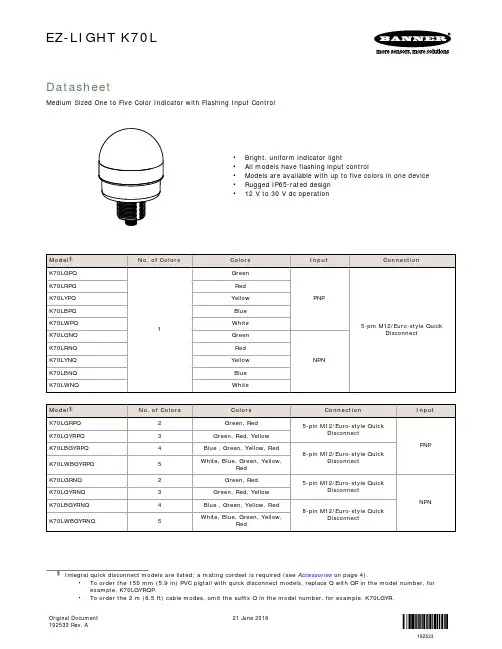
EZ-LIGHT K70LDatasheetMedium Sized One to Five Color Indicator with Flashing Input Control•Bright, uniform indicator light•All models have flashing input control•Models are available with up to five colors in one device•Rugged IP65-rated design•12 V to 30 V dc operation•To order the 150 mm (5.9 in) PVC pigtail with quick disconnect models, replace Q with QP in the model number, for example, K70LGYRQP.•To order the 2 m (6.5 ft) cable modes, omit the suffix Q in the model number, for example, K70LGYR.21 June 2016Original Document192533 Rev. A192533Wiring - Tel: +1-763-544-3164P/N 192533 Rev. ASpecificationsSupply Voltage and Current12 V to 30 V dc200 mA Max. at 12 V dc90 mA Max. at 30 V dcSupply Protection CircuitryProtected against reverse polarity and transient voltages Input Response Time75 ms maximumAdjustments1.5 Hz flash rate via flash input wireConstructionBase and dome: PolycarbonateConnectionsIntegral 5-pin or 8-pin M12/Euro-style quick disconnect, or 150 mm (6 in) PVC pigtail with quick disconnect, or 2 m (6.5 ft) cable, depending on modelIndicators1 to 5 colors, depending on modelOnly one color can be on at a time. The higher color number overrides the lower color number.Light CharacteristicsEnvironmental RatingIEC IP65Vibration and Mechanical ShockAll models meet Mil Std. 202F requirements. Method 201A (vibration:10 Hz to 60 Hz max., double amplitude 0.06 inch, maximumacceleration 10G). Also meets IEC 947-5-2 requirements: 30G 11 ms duration, half sine wave.Operating Conditions−40 °C to +50 °C (−40 °F to +122 °F)CertificationsRequired Overcurrent ProtectionWARNING:Electrical connections must be madeby qualified personnel in accordance with localand national electrical codes and regulations.Overcurrent protection is required to be provided by end productapplication per the supplied table.Overcurrent protection may be provided with external fusing or via Current Limiting, Class 2 Power Supply.Supply wiring leads < 24 AWG shall not be spliced.For additional product support, go to http://.DimensionsQuick Disconnect ModelsP/N 192533 Rev. A - Tel: +1-763-544-31643AccessoriesCordsetsElevated Mount System - Tel: +1-763-544-3164P/N 192533 Rev. ALMB Sealed Right-Angle BracketsP/N 192533 Rev. A - Tel: +1-763-544-31645Banner Engineering Corp. Limited WarrantyBanner Engineering Corp. warrants its products to be free from defects in material and workmanship for one year following the date of shipment. Banner Engineering Corp. will repair or replace, free of charge, any product of its manufacture which, at the time it is returned to the factory, is found to have been defective during the warranty period. This warranty does not cover damage or liability for misuse, abuse, or the improper application or installation of the Banner product.THIS LIMITED WARRANTY IS EXCLUSIVE AND IN LIEU OF ALL OTHER WARRANTIES WHETHER EXPRESS OR IMPLIED (INCLUDING, WITHOUT LIMITATION, ANY WARRANTY OF MERCHANTABILITY OR FITNESS FOR A PARTICULAR PURPOSE), AND WHETHER ARISING UNDER COURSE OF PERFORMANCE, COURSE OF DEALING OR TRADE USAGE.This Warranty is exclusive and limited to repair or, at the discretion of Banner Engineering Corp., replacement. IN NO EVENT SHALL BANNER ENGINEERING CORP. BE LIABLE TO BUYER OR ANY OTHER PERSON OR ENTITY FOR ANY EXTRA COSTS, EXPENSES, LOSSES, LOSS OF PROFITS, OR ANY INCIDENTAL, CONSEQUENTIAL OR SPECIAL DAMAGES RESULTING FROM ANY PRODUCT DEFECT OR FROM THE USE OR INABILITY TO USE THE PRODUCT, WHETHER ARISING IN CONTRACT OR WARRANTY, STATUTE, TORT, STRICT LIABILITY, NEGLIGENCE, OR OTHERWISE.Banner Engineering Corp. reserves the right to change, modify or improve the design of the product without assuming any obligations or liabilities relating to any product previously manufactured by Banner Engineering Corp.Copyright NoticeAny misuse, abuse, or improper application or installation of this product or use of the product for personal protection applications when the product is identified as not intended for such purposes will void the product warranty. Any modifications to this product without prior express approval by Banner Engineering Corp will void the product warranties. All specifications published in this document are subject to change; Banner reserves the right to modify product specifications or update documentation at any time. For the most recent version of any documentation, refer to: . © Banner Engineering Corp. All rights reserved. - Tel: +1-763-544-3164。
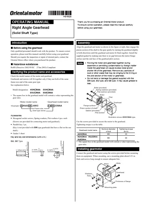
HG-9026Right Angle Gearhead(Solid Shaft Type)Thank you for purchasing an Oriental Motor product.To ensure correct operation, please read this manual carefully before using your gearhead.Before using the gearhead Only qualified personnel should work with the product. To ensure correct operation, please read this manual carefully before using your gearhead. Should you require the inspection or repair of internal parts, contact the Oriental Motor office where you purchased the product.Hazardous substances RoHS (Directive 2002/95/EC 27Jan.2003) CompliantCheck the model names of the motor and gearhead.Gearheads and motors will fit together only if they are both of the same frame size and of the same gear type. See explanation below.Model designation: 4GN RAA 5GN RAA5GU RAA 5GE RAA∗ The square box in the gearhead model will contain a value representing the gear ratio.<Example>5 IK60 GE -AW25 GE 25RAAFrame size Gear type series䊶Motor model name䊶Gearhead model nameAccessories• Hexagonal socket screws, Spring washers, Flat washers 4 pcs. each (Screws are provided for connecting motor and gearhead.)• Parallel key 1 pc.(Key is not provided with GN type gearheads that have a flat on the our shaft.)• Gasket 1 sheetKey and key slot dimensions (Unit = in.)GU , GE Type1.125±0.00790.1875+0.00160.18750-0.00120.18750-0.00120.108+0.0039Installation hole dimensions (Unit: in.)A±0.010A±0.0104×ØEB ±0.010C ±0.010ØDo r mo r eGearheadmodel nameScrew type Thicknessof flangeA B C ØDØE 4GN RAA No.10-24UNC 0.35 1.10 2.17 0.98 1.380.225GN RAA 1/4-20UNC 0.39 1.14 2.24 1.30 1.460.275GU RAA5GE RAA5/16-18UNC 0.47 1.18 2.64 1.30 1.380.33∗ The square box in the gearhead model will contain a value representing the gear ratio.The shaft of the gearhead has been machined to an outer diameter tolerance of h7 and is provided with a key slot for connecting the transmission parts. When connecting the transmission parts, ensure that the shaft and parts have a clearance fit, and secure with a screw to prevent the parts from wobbling. Use a screw hole (No.10-24UNC, effective depth 0.39 in.) provided at the tip of the output shaft of 5GU RAA and 5GE RAA as an auxiliary means for preventing the transfer mechanism from disengaging.< The example of output axistip screw hole use >Note • Do not use excessive force, or hammerthe transmission parts onto the gearmotor shaft as damage may occur. • Output shaft of 5GU120RAA to 5GU180RAA , 5GE120RAA to5GE180RAA cannot be turned by hand.For position alignment, turn on the motor.• Use your gearmotor under ambient temperature of +14 to +122 °F and85% humidity.• Do not use your gearmotor where it may be exposed direct sunlight waterand/or oil.• Do not use your gearmotor in locations subject to severe vibration or shock,a large amount of dust, inflammable gas and or corrosive gas.• On rare occasions, a small amount of grease may ooze out from thegearhead. If there is concern over possible environmental damage resulting from the leakage of grease, check for grease stains during regular inspections. Alternatively, install an oil pan or other device to prevent leakage from causing further damage. Oil leakage may lead to problems in the customer’s equipment or products.• If the ambient temperature is low, the motor may take a longer time to startor its speed may drop. This is caused, among others, by an increased friction torque of the oil seal used on the gearhead output shaft. As the motor continues to operate and the sliding part of the oil seal breaks in, the friction torque will drop and the motor will operate at the specified speed.• Direction of rotation of the gearhead output shaftThe motor and gearhead output shaft rotate in opposite directions.• Maximum permissible torqueSince the output torque of the gearhead increases proportionally with the reduction of speed, a high reduction ratio of the gearhead will result in anoutput torque that cannot be taken up by the physical construction of the gearhead. Use gearheads within the maximum permissible torque set for each speed reduction ratio. Also, be sure shaft rotation is not stopped by an external force or load obstruction. The resulting shock may damage the gearhead.• Permissible overhung load and permissible thrust load“Overhung load” refers to load placed on the output shaft of the gearhead in a direction perpendicular to the shaft as shown in the Figure below. The “Thrust load” is a load applied in the axial direction of the output shaft. Since the overhung load and thrust load have a great influence on the life of the bearings and strength of the shaft, be careful not to exceed the maximum values shown in the table at following.< Permissible overhung load and permissible thrust load >Permissibleoverhung load (lb)From the endof shaftGearhead model nameGear ratioMaximum permissibletorque(lb-in)0.39 in. 0.79 in.Permissible thrust load(lb)3 to 18 22 334GN RAA 25 to 18070 45 67 223 to 18 56 785GN RAA25 to 18088 67 101 453 to 9 90 11212.5 to 25101 135 5GU RAA 5GE RAA30 to 180177 112 15756∗ The square box in the gearhead model will contain a value representing thegear ratio.• Unauthorized reproduction or copying of all or part of this OperatingManual is prohibited.• Oriental Motor shall not be liable whatsoever for any patent-relatedproblem arising in connection with the use of any information, circuit, equipment or device described in the manual.• Characteristics, specifications and dimensions are subject to changewithout notice.• While we make every effort to offer accurate information in the manual,we welcome your input. Should you find unclear descriptions, errors or omissions, please contact the nearest office.•is a trademark of Oriental Motor Co., Ltd.© Copyright ORIENTAL MOTOR CO., LTD. 2006• Please contact your nearest Oriental Motor office for further information.ORIENTAL MOTOR U.S.A. CORP .Technical Support Line Tel:(800)468-3982Available from 7:30 AM to 5:00 PM, P .S.T.E-mail:*****************************ORIENTAL MOTOR CO., LTD.Headquarters Tokyo, JapanTel:(03)3835-0684 Fax:(03)3835-1890Printed on Recycled Paper。
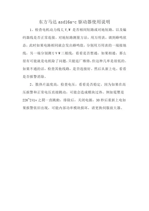
东方马达asd16a-c驱动器使用说明
1、检查电机动力线U,V,W 是否相间短路或对地短路,以及编码器线是否正常连接。
对地短路测量方法,用万用表,调到蜂鸣状态,此时如果电路相同就会发出蜂鸣值,分别用万用表的一端接地线,另一端分别测U V W三根线,看看是否想通,如果相通,那么很有可能就是电机除了问题,只能返厂维修,但这种几率是很低的。
如果不通的话,检查其他线路,是否连接好。
然后从新上电。
看看是否报警消除。
2、散热片温度高,检查电压,看看是否稳定,因为如果在高压报警和正常电压直接跳动,可能会造成模块过热。
例如電壓是226~241v之間一直跳動,排除后,关闭电源,30秒后重新上电如果报警依旧出现,可能内部功率模块损坏,请更换伺服放大器。
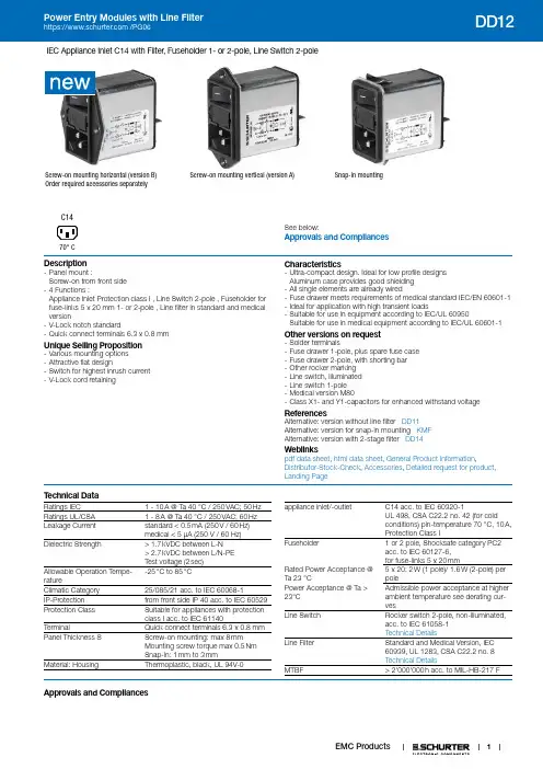
1IEC Appliance Inlet C14 with Filter, Fuseholder 1- or 2-pole, Line Switch 2-poleScrew-on mounting horizontal (version B)Order required accessories separatelyScrew-on mounting vertical (version A)Snap-in mountingSee below:Approvals and CompliancesC1470° CDescription- Panel mount :Screw-on from front side - 4 Functions :Appliance Inlet Protection class I , Line Switch 2-pole , Fuseholder for fuse-links 5 x 20 mm 1- or 2-pole , Line filter in standard and medical version- V-Lock notch standard- Quick connect terminals 6.3 x 0.8 mmUnique Selling Proposition- Various mounting options - Attractive flat design- Switch for highest inrush current - V-Lock cord retainingCharacteristics- Ultra-compact design. Ideal for low profile designs Aluminum case provides good shielding - All single elements are already wired- Fuse drawer meets requirements of medical standard IEC/EN 60601-1- Ideal for application with high transient loads- Suitable for use in equipment according to IEC/UL 60950Suitable for use in medical equipment according to IEC/UL 60601-1Other versions on request- Solder terminals- Fuse drawer 1-pole, plus spare fuse case - Fuse drawer 2-pole, with shorting bar - Other rocker marking - Line switch, illuminated - Line switch 1-pole - Medical version M80- Class X1- and Y1-capacitors for enhanced withstand voltageReferencesAlternative: version without line filter DD11 Alternative: version for snap-in mounting KMF Alternative: version with 2-stage filter DD14Weblinkspdf data sheet , html data sheet , General Product Information ,Distributor-Stock-Check , Accessories , Detailed request for product , Landing PageT echnical DataRatings IEC1 - 10 A @ Ta 40 °C / 250 VAC; 50 Hz Ratings UL/CSA 1 - 8 A @ Ta 40 °C / 250 VAC; 60 Hz Leakage Current standard < 0.5 mA (250 V / 60 Hz) medical < 5 µA (250 V / 60 Hz)Dielectric Strength> 1.7 kVDC between L-N > 2.7 kVDC between L/N-PE Test voltage (2 sec)Allowable Operation Tempe-rature-25 °C to 85 °CClimatic Category 25/085/21 acc. to IEC 60068-1IP-Protection from front side IP 40 acc. to IEC 60529Protection Class Suitable for appliances with protection class I acc. to IEC 61140TerminalQuick connect terminals 6.3 x 0.8 mm Panel Thickness SScrew-on mounting: max 8 mm Mounting screw torque max 0.5 Nm Snap-in: 1 mm to 3 mmMaterial: HousingThermoplastic, black, UL 94V-0appliance inlet/-outletC14 acc. to IEC 60320-1UL 498, CSA C22.2 no. 42 (for cold conditions) pin-temperature 70 °C, 10 A, Protection Class IFuseholder1 or2 pole, Shocksafe category PC2 acc. to IEC 60127-6, for fuse-links 5 x 20 mmRated Power Acceptance @ Ta 23 °C5 x 20: 2 W (1 pole)/ 1.6 W (2-pole) per polePower Acceptance @ Ta > 23°C Admissible power acceptance at higher ambient temperature see derating cur-vesLine SwitchRocker switch 2-pole, non-illuminated, acc. to IEC 61058-1 Technical DetailsLine FilterStandard and Medical Version, IEC 60939, UL 1283, CSA C22.2 no. 8 Technical DetailsMTBF> 2'000'000 h acc. to MIL-HB-217 FApprovals and CompliancesDetailed information on product approvals, code requirements, usage instructions and detailed test conditions can be looked up in Details about ApprovalsSCHURTER products are designed for use in industrial environments. They have approvals from independent testing bodies according to national and international standards. Products with specific characteristics and requirements such as required in the automotive sector according to IATF 16949, medical technology according to ISO 134485 or in the aerospace industry can be offered exclusively with customer-specific, individual agree-ments by SCHURTER.ApprovalsThe approval mark is used by the testing authorities to certify compliance with the safety requirements placed on electronic products.Approval Reference T ype: DD12Approval Logo Certificates Certification Body DescriptionVDE Approvals VDE Certificate Number: 40001522UL Approvals ULUL File Number: E72928CQC Approvals CQC CQC File Number: CQC19001211536 Product standardsProduct standards that are referencedOrganization Design StandardDescriptionDesigned according to IEC 60320-1Appliance couplers for household and similar general purposesDesigned according to IEC 60939Passive filters for suppressing electromagnetic interferenceDesigned according to IEC 60127-6Miniature fuses. Part 6. Fuse-holders for miniature fuse-linksDesigned according to IEC 61058-1Switches for appliances. Part 1. General requirements Designed according to UL 498Standard for Attachment Plugs and ReceptaclesDesigned according to UL 1283Electromagnetic interference filtersDesigned according to CSA C22.2 no. 42General Use Receptacles, Attachment Plugs, and Similar Wiring DevicesDesigned according to CSA C22.2 no. 8Electromagnetic interference (EMI) filters Application standardsApplication standards where the product can be usedOrganization Design StandardDescriptionDesigned for applications acc.IEC/UL 60950IEC 60950-1 includes the basic requirements for the safety of informationtechnology equipment.Designed for applications acc.IEC 60601-1Medical electrical equipment - Part 1: General requirements for basicsafety and essential performanceDesigned for applications acc.IEC 60335-1Safety of electrical appliances for household and similar purposes. Meetsthe requirements for appliances in unattended use. This includes theenhanced requirements of glow wire tests acc. to IEC 60695-2-11 or -12& -13.2CompliancesThe product complies with following Guide LinesIdentification Details Initiator DescriptionCE declaration of conformity SCHURTER AG The CE marking declares that the product complies with the applicablerequirements laid down in the harmonisation of Community legislation onits affixing in accordance with EU Regulation 765/2008.RoHS SCHURTER AG EU Directive RoHS 2011/65/EUChina RoHS SCHURTER AG The law SJ / T 11363-2006 (China RoHS) has been in force since 1 March2007. It is similar to the EU directive RoHS.REACH SCHURTER AG On 1 June 2007, Regulation (EC) No 1907/2006 on the Registration,Evaluation, Authorization and Restriction of Chemicals 1 (abbreviated as"REACH") entered into force.SCHURTER AG V-Lock system are based on a matching plug-dose combination. Theconnector is equipped with a notch intended for use with the latchingcordset. The cord latching system prevents against accidental removal ofthe cordset.White paper Glow wire test SCHURTER AG Meets the requirements of IEC 60335-1 for appliances in unattended use.This includes the enhanced requirements of glow wire tests acc. to IEC60695-2-11 or -12 &-13.Medical Equipment SCHURTER AG Suitable for use in medical equipment according to IEC/UL 60601-1 Dimensions [mm]Screw version A3Screw version BSnap-in mounting from front side45DiagramsStandard Version, medical Version M80 non-illuminatedL PE L’PE’N’1)2)1) Line 2) LoadMedical version M5 non-illuminatedLPE L’PE’N’1)2)1) Line2) LoadStandard Version, medical Version M80 with PE-chokeL PE L’PE’N’1)2)1) Line 2) Load Medical version M5 with PE-chokeLPE L’PE’N’1)2)1) Line 2) LoadDerating Curves 1-poleA d m i s s i b l e p o w e r a c c e p t a n c e i n W a t tAmbient air temperature Ta °C 2-poleA d m i s s i b l e p o w e r a c c e p t a n c e i n W a t tAmbient air temperature Ta °C6Attenuation Loss- - - - 50Ω differential mode _____ 50Ω common modeStandard version1 A2 A4 A6 A8 A10 AMedical version (M5)1 A2 A4 A6 A8 A10 AAll VariantsPackaging unit 10 Pcs7Required AccessoryDescriptionFusedrawer 2Fusedrawer für Fuse Links 5x20 mm, with or without Voltage Selector InsertFingergrip, 2-pole4301.1401Extra-Safe, 2-pole4301.1403Fingergrip, 1-pole4301.1405 Extra-Safe, 1-pole4301.1407...AccessoriesWire HarnessWire harness for SCHURTER productsAssorted CoversRear Cover0859.0076 Cord retaining kitsCord retaining strain reliefFlat head, A4700.0001Mating Outlets/ConnectorsCategory / DescriptionAppliance Outlet Overview complete4787, Mounting: Screw-on mounting, Appliance Outlet: IEC Solder terminals, 10 A, Suitable for appliances with pro-tection class I47874788, Mounting: Snap-in version, Appliance Outlet: IEC Solder terminals or quick connect terminals, 10 A, Suitable forappliances with protection class I4788IEC Appliance Outlet F or H, Screw-on Mounting, Front Side, Solder, PCB or Quick-connect Terminal5091Appliance Outlet further types to DD12Connector Overview complete4782 Mounting: Power Cord, 3 x 1 mm² / 3 x 18 AWG, Cable, Connector: IEC C1347824785 Mounting: Power Cord, 3 x 1 mm² / 3 x 18 AWG, Cable, Connector: IEC C1347854300-06 Mounting: Power Cord, 3 x 1 mm² / 3 x 18 AWG, Cable, Connector: IEC C134300-064781 Mounting: Power Cord, 3 x 1 mm² / 3 x 18 AWG, Cable, Connector: IEC C1547814784 Mounting: Power Cord, 3 x 1 mm² / 3 x 18 AWG, Cable, Connector: IEC C154784Connector further types to DD12...89Mating Outlets/Connectors shutteredPower Cord Overview completeVAC13KS, Overview, V-Lock cord retaining, diverse Connector IEC C13, diverse, black VAC13KSPower Cord further types to DD12The specifications, descriptions and illustrations indicated in this document are based on currentinformation. All content is subject to modifications and amendments. Information furnished is believed 25.01.2019。
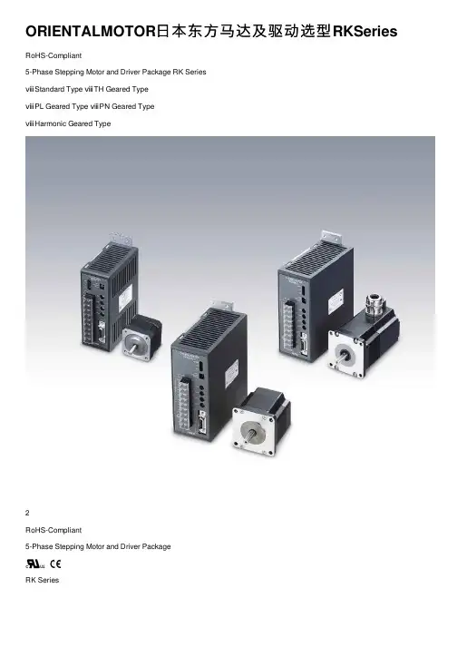
ORIENTALMOTOR⽇本东⽅马达及驱动选型RKSeries RoHS-Compliant5-Phase Stepping Motor and Driver Package RK SeriesⅷStandard Type ⅷTH Geared TypeⅷPL Geared Type ⅷPN Geared TypeⅷHarmonic Geared Type2RoHS-Compliant5-Phase Stepping Motor and Driver PackageRK SeriesThe RK Series incorporates new functions and state-of-the-art technologies to achieve the ultimate use of a control motor. The seriesoffers various types including the standard type, electromagnetic brake type, IP65 rated motor type, and four geared types. Three frame sizes of 42 mm, 60 mm and 85 (90) mm are available. The wide range of motor variations and affordable prices make the RK Series a perfect solution for your various applications.ⅥFeaturesv bz Smooth Drive FunctionThe smooth drive function ensures low-vibration andlow-noise operation at low speeds by internally executing microstepping within the driver, working independently of the inputpulse frequency of your controller.V i b r a t i o n C o m p o n e n t V o l t a g e V p -p [V ]Speed [r/min]The smooth drive function of the RK Series improves the settling performance.S p e e d [r /m i n ]S p e e d [r /m in ]Conventional Model RK (Smooth Drive: ON)100 ms/div100 ms/divStep Angle: 0.72?/stepStep Angle: 0.72?/stepx Microstep Drive SystemThe motor's basic step angle is divided by a maximum of 1/250 without the use of a reduction mechanism or other mechanical elements. 16 resolution levels are available to set the desired resolution. This enables fine positioning and the further reduction of vibration and noise. A motion sequence of "low-speed transfer ? high-speed return" can easily be performed without the need for changing from a microstep pulse frequency to a full step pulse frequency. The RK Series can also be used in full-step operation.c 100-115 VAC, 200-230 VAC Power Source Variation The RK Series can be used with most common power supplies available around the world.They also comply with the international standards, ensuring safe operation.v Improved Angle AccuracyAngle accuracy may decrease during use of microstep drivers, due to the effect of current control. However, the drivers used in the RK Series are designed to ensure that the motor operates at maximum accuracy.A n g l e E rr o r [d e g ]0.0720.036-0.072-0.036Power Supply Voltage: 100-115 VAC b Improved ResponseThe RK Series, with its high starting frequency, shortens the machine cycle without affecting acceleration/deceleration rates. This produces a significant savings in time for an operation in which the same cycle is repeated thousands of times each day.Rise Time [ms]S p e e d [r /m i n ]3Features Line-upSystem ConfigurationProduct LineSpecifications and Characteristics DimensionsConnection and Operation List of Motor and Driver CombinationsAccessoriesBefore Using a Stepping MotorControllersⅷEnvironmentally Friendly Energy-Saving Mode In the energy-saving mode, the supply of current to the motor is stopped and the load is held only with the electromagnetic brake while the motor remains at a standstill. Stopping the supply of current to the motor extends the motor life by limiting the consumption of energy.(Available only with electromagnetic brake type)P o w e r C o n s u m p t i o n [k W ]Automatic Current-Cutback Modein Energy-Saving ModeComparison of Annual Power Consumption at ⅷSafe Operation in Major Countries around the World Compliance with Safety StandardsThe RK Series complies with the UL/CSA and ENstandards. (With the RK54Ⅺ type, only the driver conforms to the CSA standard.) The CE marking certifies compliance with the EMC Directive and Low-Voltage Directive.Additionally, the RK Series conforms to the EMC Directive only through its use of surge arrester. The RK Seriesdoesn't require an external ferrite core or filter in the motor line or power line.ⅷProtective Earth Terminal(Excluding motors with a frame size of 42 mm)The life of a motor is affected by its bearing. The RK Series achieves approx. twice the life of a conventional motor by adopting a modified bearing. (Available only with the standard type and standard electromagnetic-brake type with a frame size of 60 or 85 mm.)ⅷNew IP65 Rated Motor Conforming to the IP65 Standard for Ingress Protection against Dust and WaterTerminal-Block Connection DesignThe motor can be wired directly from its terminal block.No Motor/Driver RelaySince the motor cable can be connected directly with the driver terminals, there is no need for wire connection orsoldering on a relay terminal block.DriverRoHS-CompliantThe RK Series conforms to the RoHS Directive thatprohibits the use of six chemical substances including lead and cadmium.ⅥWide VarietyThe RK Series offers a range of motor frame sizes depending on the motor type and power supply voltage specification, as shown below.□ⅷStandard Type/Standard Type IP65 Rated MotorEasy-to-use standard types offer balanced performance. The IP65 rated motor conforms to the IP65 standard for ingress protectionagainst dust and water.ⅷStandard Type with Electromagnetic BrakeA motor combines with power off activated type electromagnetic brake.TH Geared Type (Low backlash)A low-cost geared motor offers low backlash.ⅷPL Geared Type (Low backlash)A geared motor offers low backlash, high strength and wide gear ratios.ⅷPNGeared Type (Non-backlash)A high-accuracy geared motor achieves a backlash of 3 arc minutes or less. It also provides high strength and wide gear ratios.Harmonic Geared Type(Non-backlash)A high-accuracy, backlash-free geared motor adopts a newly developed harmonic gear. It ensures high strength in a compact body.45FeaturesLine-upSystem ConfigurationProduct LineSpecifications and CharacteristicsDimensionsConnection and Operation List of Motor and Driver Combinations Accessories Before Using a Stepping Motor ControllersTH (Parallel Shaft)PL (Harmonic Drive)ⅥSystem ConfigurationAn example of a system configuration with the SG8030 Series controller.Mounting Brackets (Accessories)Connector-Terminal BlockDriverⅷThe system configuration shown above is an example. Other combinations are available.67Features Line-upSystem ConfigurationProduct LineSpecifications and CharacteristicsDimensionsConnection and Operation List of Motor and Driver CombinationsAccessoriesBefore Using a Stepping Motor ControllersⅥProduct Number Codeqw e r t y u io !0RK 5 6 6 B A E - N 5Series RK :RK Series 5: 5-PhaseMotor Frame Size 4: 42 mm6: 60 mm 9: 85 mm (90 mm sq. for Geared Type)Motor Case LengthMotor Shaft Type A : Single Shaft B : Double ShaftElectromagnetic Brake Blank : Without Electromagnetic Brake M : With Electromagnetic Brake Power Supply Voltage A : Single-Phase 100-115 VAC C : Single-Phase 200-230 VAC Motor Classi? c ation TypeBlank : Standard Type T :TH Geared TypeP :PL Geared Type N :PN Geared Type H : Harmonic Geared TypeGear RatioⅥProduct Line89 Features Line-up System ConfigurationProduct LineSpecifications and CharacteristicsDimensionsConnection and Operation List of Motor and Driver CombinationsAccessoriesBefore Using a Stepping Motor ControllersStandard Type Motor Frame Size 42 mmⅥSpecificationsⅷWith the RK54Ⅺ type, only the driver conforms to the CSA standard.RK543AA RK544AA RK545AA RK543BA RK544BA RK545BAHow to Read Specifications Table ?See the following descriptions.Sixteen resolutions are available, where n=1, 2, 2.5, 4, 5, 8, 10, 20, 25, 40, 50, 80, 100, 125, 200 and 250.ⅥSpeed – Torque Characteristics fs: Maximum Starting FrequencyRK543AA/RK543BAPulse Speed [kHz](0)(300)(200)(100)(Resolution 10)Speed [r/min]T o r q u e [N ?m ]C u r r e n t [A ]132Current: 0.75 A/Phase Step Angle: 0.72?/step 2RK544AA/RK544BAPulse Speed [kHz]0(0)30(300)20(200)10(100)Resolution 1(Resolution 10)Speed [r/min]T o r q u e [N ?m ]C u r r e n t [A ]132Current: 0.75 A/Phase Step Angle: 0.72?/step 2RK545AA/RK545BAPulse Speed [kHz]0(0)30(300)20(200)10(100)Resolution 1(Resolution 10)Speed [r/min]T o r q u e [N ?m ]C u r r e n t [A ]132Current: 0.75 A/Phase Step Angle: 0.72?/step 2ⅷThe pulse input circuit responds to approximately 200 kHz with a pulse duty of 50%.Notes:ⅷPay attention to heat dissipation from motor as there will be a considerable amount of heat under certain conditions.Be sure to keep the temperature of the motor case under 100?C.(Under 75?C is required to comply with UL or CSA standards.)ⅷWhen using the motor with the dedicated driver, the driver’s automatic current cutback function at motor standstill reduces maximum holding torque by approximately 50%.ⅥHow to Read Specifications TablePlease read the following information before examining the specifications on pages 9 to 23.10Standard Type Motor Frame Size 60 mm, 85 mmHow to Read Specifications Table ?Page 9Sixteen resolutions are available, where n=1, 2, 2.5, 4, 5, 8, 10, 20, 25, 40, 50, 80, 100, 125, 200 and 250.ⅥSpeed – Torque Characteristics fs: Maximum Starting FrequencyRK564ⅪAE RK564ⅪCEPulse Speed [kHz]0(0)10(100)20(200)30(300) Speed [r/min]T o r q u e [N ?m ]Resolution 1(Resolution 10)C u r r e n t [A ]462Current: 1.4 A/Phase Step Angle: 0.72?/step 2RK566ⅪAE RK566ⅪCEPulse Speed [kHz](0)10(100)20(200)30(300) Speed [r/min]T o r q u e [N ?m ]Resolution 1(Resolution 10)C u r r e n t [A ]48Current: 1.4 A/Phase Step Angle: 0.72?/step 2RK569ⅪAE RK569ⅪCEPulse Speed [kHz]0(0)10(100)20(200)30(300) Speed [r/min]T o r q u e [N ?m ]Resolution 1(Resolution 10)C u r r e n t [A ]48Current: 1.4 A/Phase Step Angle: 0.72?/step 2ⅷEnter A (Single shaft) or B (Double shaft) in the box (Ⅺ) within the model name.ⅷThe pulse input circuit responds to approximately 200 kHz with a pulse duty of 50%.Notes:ⅷPay attention to heat dissipation from motor as there will be a considerable amount of heat under certain conditions.Be sure to keep the temperature of the motor case under 100?C.(Under 75?C is required to comply with UL or CSA standards.)ⅷWhen using the motor with the dedicated driver, the driver’s automatic current cutback function at motor standstill reduces maximum holding torque by approximately 50%.RK596ⅪAE RK596ⅪCEPulse Speed [kHz](0)(100)(200) Speed [r/min](Resolution 10)T o r q u e [N ?m ]C u r r e n t [A ]510Current: 1.4 A/Phase Step Angle: 0.72?/step 2 RK599ⅪAE RK599ⅪCEPulse Speed [kHz]Speed [r/min](Resolution 10)(0)(50)(100)T o r q u e [N ?m ]C u r r e n t [A ]48Current: 1.4 A/Phase Step Angle: 0.72?/step 2 RK5913ⅪAERK5913ⅪCEPulse Speed [kHz](0)(50)(100) Speed [r/min](Resolution 10)T o r q u e [N ?m ]C u r r e n t [A ]48Current: 1.4 A/Phase Step Angle: 0.72?/step 2 11FeaturesLine-upSystem ConfigurationProduct LineSpecifications and Characteristics DimensionsConnection and Operation List of Motor and Driver CombinationsAccessoriesBefore Using a Stepping Motor ControllersStandard Type IP65 Rated Motor Motor Frame Size 60 mm, 85 mmⅥSpecificationsHow to Read Specifications Table ?Page 91Sixteen resolutions are available, where n=1, 2, 2.5, 4, 5, 8, 10, 20, 25, 40, 50, 80, 100, 125, 200 and 250.2Excluding the gap between the shaft and the flangeⅥSpeed – Torque Characteristics fs: Maximum Starting FrequencyRK564AAT/RK564ACTPulse Speed [kHz]0(0)10(100)20(200)30(300)Speed [r/min]T o r q u e [N ?m ]Resolution 1(Resolution 10)C u r r e n t [A ]462Current: 1.4 A/Phase Step Angle: 0.72?/step 2RK566AAT/RK566ACTPulse Speed [kHz]0(0)10(100)20(200)30(300) Speed [r/min]T o r q u e [N ?m ]Resolution 1(Resolution 10)C u r r e n t [A ]48Current: 1.4 A/Phase Step Angle: 0.72?/step 2RK569AAT/RK569ACTPulse Speed [kHz]0(0)10(100)20(200)30(300) Speed [r/min]T o r q u e [N ?m ]Resolution 1(Resolution 10)C u r r e n t [A ]48Current: 1.4 A/Phase Step Angle: 0.72?/step 2ⅷThe pulse input circuit responds to approximately 200 kHz with a pulse duty of 50%.Notes:ⅷPay attention to heat dissipation from motor as there will be a considerable amount of heat under certain conditions.Be sure to keep the temperature of the motor case under 100?C.(Under 75?C is required to comply with UL or CSA standards.)ⅷWhen using the motor with the dedicated driver, the driver’s automatic current cutback function at motor standstill reduces maximum holding torque by approximately 50%.RK596AAT/RK596ACTPulse Speed [kHz]0(0)10(100)20(200) Speed [r/min]Resolution 1(Resolution 10)T o r q u e [N ?m ]C u r r e n t [A ]510Current: 1.4 A/Phase Step Angle: 0.72?/step2RK599AAT/RK599ACTPulse Speed [kHz]Speed [r/min]Resolution 1(Resolution 10)0(0)5(50)10(100)T o r q u e [N ?m ]C u r r e n t [A ]48Current: 1.4 A/Phase Step Angle: 0.72?/step 2RK5913AAT/RK5913ACTPulse Speed [kHz]0(0)5(50)10(100) Speed [r/min]Resolution 1(Resolution 10)T o r q u e [N ?m ]C u r r e n t [A ]48Current: 1.4 A/Phase Step Angle: 0.72?/step 212Standard Type with Electromagnetic Brake Motor Frame Size 42 mm ⅥSpecificationsⅷWith the RK54Ⅺtype, only the driver conforms to the CSA standard.How to Read Specifications Table ?Page 9Sixteen resolutions are available, where n=1, 2, 2.5, 4, 5, 8, 10, 20, 25, 40, 50, 80, 100, 125, 200 and 250.ⅥSpeed – Torque Characteristics fs: Maximum Starting FrequencyRK543AMAPulse Speed [kHz]0(0)30(300)20(200)10(100)Resolution 1(Resolution 10)Speed [r/min]T o r q u e [N ?m ]C u r r e n t [A ]132Current: 0.75 A/Phase Step Angle: 0.72?/step 2RK544AMAPulse Speed [kHz]0(0)30(300)20(200)10(100)Resolution 1(Resolution 10)Speed [r/min]T o r q u e [N ?m ]C u r r e n t [A ]132Current: 0.75 A/Phase Step Angle: 0.72?/step 2RK545AMAPulse Speed [kHz]0(0)30(300)20(200)10(100)Resolution 1(Resolution 10)Speed [r/min]T o r q u e [N ?m ]C u r r e n t [A ]132Current: 0.75 A/Phase Step Angle: 0.72?/step 2ⅷThe pulse input circuit responds to approximately 200 kHz with a pulse duty of 50%.Notes:ⅷPay attention to heat dissipation from motor as there will be a considerable amount of heat under certain conditions.Be sure to keep the temperature of the motor case under 100?C.(Under 75?C is required to comply with UL or CSA standards.)ⅷWhen using the motor with the dedicated driver, the driver’s automatic current cutback function at motor standstill reduces maximum holding torque by approximately 50%.13FeaturesLine-upSystem Configuration Product LineSpecifications and CharacteristicsDimensionsConnection and Operation List of Motor and Driver CombinationsAccessoriesBefore Using a Stepping Motor ControllersStandard Type with Electromagnetic Brake Motor Frame Size 60 mm, 85 mmⅥSpecificationsHow to Read Specifications Table ?Page 9Sixteen resolutions are available, where n=1, 2, 2.5, 4, 5, 8, 10, 20, 25, 40, 50, 80, 100, 125, 200 and 250.ⅥSpeed – Torque Characteristics fs: Maximum Starting FrequencyRK564AMAE RK564AMCEPulse Speed [kHz]0(0)10(100)20(200)30(300)Speed [r/min]T o r q u e [N ?m ]Resolution 1(Resolution 10)C u r r e n t [A ]462Current: 1.4 A/Phase Step Angle: 0.72?/step 2RK566AMAE RK566AMCEPulse Speed [kHz]0(0)10(100)20(200)30(300) Speed [r/min]T o r q u e [N ?m ]Resolution 1(Resolution 10)C u r r e n t [A ]48Current: 1.4 A/Phase Step Angle: 0.72?/step 2RK569AMAE RK569AMCEPulse Speed [kHz]0(0)10(100)20(200)30(300) Speed [r/min]T o r q u e [N ?m ]Resolution 1(Resolution 10)C u r r e n t [A ]48Current: 1.4 A/Phase Step Angle: 0.72?/step 2ⅷThe pulse input circuit responds to approximately 200 kHz with a pulse duty of 50%.Notes:ⅷPay attention to heat dissipation from motor as there will be a considerable amount of heat under certain conditions.Be sure to keep the temperature of the motor case under 100?C.(Under 75?C is required to comply with UL or CSA standards.)ⅷWhen using the motor with the dedicated driver, the driver’s automatic current cutback function at motor standstill reduces maximum holding torque by approximately 50%.RK596AMAE RK596AMCEPulse Speed [kHz]0(0)10(100)20(200) Speed [r/min]Resolution 1(Resolution 10)T o r q u e [N ?m ]C u r r e n t [A ]510Current: 1.4A/Phase Step Angle: 0.72? step 2RK599AMAE RK599AMCEPulse Speed [kHz]0(0)Speed [r/min]Resolution 1(Resolution 10)5(50)10(100)T o r q u e [N ?m ]C u r r e n t [A ]48Current: 1.4 A/Phase Step Angle: 0.72?/step 2 RK5913AMAE RK5913AMCEPulse Speed [kHz]0(0)5(50)10(100) Speed [r/min]Resolution 1(Resolution 10)T o r q u e [N ?m ]C u r r e n t [A ]48Current: 1.4 A/Phase Step Angle: 0.72?/step 2 14TH Geared Type Motor Frame Size 42 mmⅥSpecificationsⅷWith the RK54Ⅺtype, only the driver conforms to the CSA standard.How to Read Specifications Table ?Page 9Sixteen resolutions are available, where n=1, 2, 2.5, 4, 5, 8, 10, 20, 25, 40, 50, 80, 100, 125, 200 and 250.Note:ⅷDirection of rotation of the motor and that of the gear output shaft are the same for models with gear ratios of 1:3.6, 1:7.2 and 1:10. It is opposite for 1:20 and 1:30 gear ratio models.ⅥSpeed – Torque Characteristics fs: Maximum Starting FrequencyRK543AA-T3.6/RK543BA-T3.6Pulse Speed [kHz]0(0)15(150)10(100)5(50)Resolution 1(Resolution 10)Speed [r/min]T o r q u e [N ?m ]C u r r e n t [A ]12Current: 0.75 A/Phase Step Angle: 0.2?/step 2RK543AA-T7.2/RK543BA-T7.2Pulse Speed [kHz]0(0)15(150)10(100)5(50)Resolution 1(Resolution 10)Speed [r/min]T o r q u e [N ?m ]C u r r e n t [A ]12Current: 0.75 A/Phase Step Angle: 0.1?/step 2RK543AA-T10/RK543BA-T10Pulse Speed [kHz]Resolution 1(Resolution 10)Speed [r/min]0(0)5(50)10(100)15(150)T o r q u e [N ?m ]C u r r e n t [A ]12Current: 0.75 A/Phase Step Angle: 0.072?/step 2ⅷThe pulse input circuit responds to approximately 200 kHz with a pulse duty of 50%.Notes:ⅷPay attention to heat dissipation from motor as there will be a considerable amount of heat under certain conditions.Be sure to keep the temperature of the motor case under 100?C.(Under 75?C is required to comply with UL or CSA standards.)ⅷWhen using the motor with the dedicated driver, the driver’s automatic current cutback function at motor standstill reduces maximum holding torque by approximately 50%.RK543AA-T20/RK543BA-T20Pulse Speed [kHz]Resolution 1(Resolution 10)Speed [r/min]0(0)5(50)10(100)15(150)T o r q u e [N ?m ]C u r r e n t [A ]12Current: 0.75 A/Phase Step Angle: 0.036?/step 2RK543AA-T30/RK543BA-T30T o rq u e [N ?m ]C u r r e n t [A ]12Pulse Speed [kHz]Resolution 1(Resolution 10)Speed [r/min]0(0)5(50)10(100)15(150)Current: 0.75 A/Phase Step Angle: 0.024?/step 215FeaturesLine-upSystemConfiguration Product LineSpecifications and CharacteristicsDimensionsConnection and Operation List of Motor and Driver Combinations AccessoriesBefore Using a Stepping MotorControllersTH Geared Type Motor Frame Size 60 mmⅥSpecificationsHow to Read Specifications Table ?Page 9Sixteen resolutions are available, where n=1, 2, 2.5, 4, 5, 8, 10, 20, 25, 40, 50, 80, 100, 125, 200 and 250.Note:ⅷDirection of rotation of the motor and that of the gear output shaft are the same for models with gear ratios of 1:3.6, 1:7.2 and 1:10. It is opposite for 1:20 and 1:30 gear ratio models.ⅥSpeed – Torque Characteristics fs: Maximum Starting FrequencyRK564ⅪAE-T3.6 RK564ⅪCE-T3.6Pulse Speed [kHz]0(0)15(150)10(100)5(50)Resolution 1(Resolution 10)Speed [r/min]T o r q u e [N ?m ]C u r r e n t [A ]24Current: 1.4 A/Phase Step Angle: 0.2?/step 2RK564ⅪAE-T7.2 RK564ⅪCE-T7.2Pulse Speed [kHz]0(0)15(150)10(100)Resolution 1(Resolution 10)Speed [r/min]T o r q u e [N ?m ]C u r r e n t [A ]48Current: 1.4 A/Phase Step Angle: 0.1?/step 2RK564ⅪAE-T10 RK564ⅪCE-T10Pulse Speed [kHz]Resolution 1(Resolution 10)Speed [r/min]0(0)5(50)10(100)15(150)T o r q u e [N ?m ]C u r r e n t [A ]24Current: 1.4 A/Phase Step Angle: 0.072?/step 2ⅷEnter A (Single shaft) or B (Double shaft) in the box (Ⅺ) within the model name.ⅷThe pulse input circuit responds to approximately 200 kHz with a pulse duty of 50%.Notes:ⅷPay attention to heat dissipation from motor as there will be a considerable amount of heat under certain conditions.Be sure to keep the temperature of the motor case under 100?C.(Under 75?C is required to comply with UL or CSA standards.)ⅷWhen using the motor with the dedicated driver, the driver’s automatic current cutback function at motor standstill reduces maximum holding torque by approximately 50%.RK564ⅪAE-T20 RK564ⅪCE-T20Pulse Speed [kHz]Resolution 1(Resolution 10)Speed [r/min]0(0)5(50)15(150)T o r q u e [N ?m ]C u r r e n t [A ]24Current: 1.4 A/Phase Step Angle: 0.036?/step 2RK564ⅪAE-T30 RK564ⅪCE-T30Pulse Speed [kHz]Resolution 1(Resolution 10)Speed [r/min]0(0)5(50)10(100)15(150)T o r q u e [N ?m ]C u r r e n t [A ]24Current: 1.4 A/Phase Step Angle: 0.024?/step 216TH Geared Type Motor Frame Size 90 mmⅥSpecificationsHow to Read Specifications Table ?Page 9Sixteen resolutions are available, where n=1, 2, 2.5, 4, 5, 8, 10, 20, 25, 40, 50, 80, 100, 125, 200 and 250.Note:ⅷDirection of rotation of the motor and that of the gear output shaft are the same for models with gear ratios of 1:3.6, 1:7.2 and 1:10. It is opposite for 1:20 and 1:30 gear ratio models.ⅥSpeed – Torque Characteristics fs: Maximum Starting FrequencyRK596ⅪAE-T3.6 RK596ⅪCE-T3.6Pulse Speed [kHz]0(0)15(150)10(100)5(50)Resolution 1(Resolution 10)Speed [r/min]T o r q u e [N ?m ]C u r r e n t [A ]2.55Current: 1.4 A/Phase Step Angle: 0.2?/step 2 RK596ⅪAE-T7.2 RK596ⅪCE-T7.2Pulse Speed [kHz]0(0)15(150)10(100)5(50)Resolution 1(Resolution 10)Speed [r/min]T o r q u e [N ?m ]C u r r e n t [A ]2.55Current: 1.4 A/Phase Step Angle: 0.1?/step 2 RK596ⅪAE-T10 RK596ⅪCE-T10Pulse Speed [kHz]Resolution 1(Resolution 10)Speed [r/min]0(0)5(50)10(100)15(150)T o r q u e [N ?m ]C u r r e n t [A ]264Current: 1.4 A/Phase Step Angle: 0.072?/step 2ⅷEnter A (Single shaft) or B (Double shaft) in the box (Ⅺ) within the model name.ⅷThe pulse input circuit responds to approximately 200 kHz with a pulse duty of 50%.Notes:ⅷPay attention to heat dissipation from motor as there will be a considerable amount of heat under certain conditions.Be sure to keep the temperature of the motor case under 100?C.(Under 75?C is required to comply with UL or CSA standards.)ⅷWhen using the motor with the dedicated driver, the driver’s automatic current cutback function at motor standstill reduces maximum holding torque by approximately 50%.RK596ⅪAE-T20 RK596ⅪCE-T20C u r r e n t [A ]Pulse Speed [kHz](Resolution 10)(0)(50)(100)(150)Current: 1.4 A/Phase Step Angle: 0.036?/step 2RK596ⅪAE-T30 RK596ⅪCE-T30C u r r e n t [A ]Pulse Speed [kHz](Resolution 10)(0)(50)(150)Current: 1.4 A/Phase Step Angle: 0.024?/step 217FeaturesLine-upSystem ConfigurationProduct LineSpecifications and CharacteristicsDimensionsConnection and Operation List of Motor and Driver CombinationsAccessoriesBefore Using a Stepping Motor ControllersPL Geared Type Motor Frame Size 42 mmⅥSpecificationsⅷWith the RK54Ⅺ type, only the driver conforms to the CSA standard.How to Read Specifications Table ?Page 9Sixteen resolutions are available, where n=1, 2, 2.5, 4, 5, 8, 10, 20, 25, 40, 50, 80, 100, 125, 200 and 250.Note:ⅷDirection of rotation of the motor and that of the gear output shaft are the same.ⅥSpeed – Torque Characteristics fs: Maximum Starting FrequencyRK545AA-P5 RK545BA-P5Pulse Speed [kHz]Resolution 1(Resolution 10)Speed [r/min]0(0)5(50)15(150)T o r q u e [N ?m ]C u r r e n t [A ]12Current: 0.75 A/Phase Step Angle: 0.144?/step 2RK545AA-P7.2RK545BA-P7.2Pulse Speed [kHz]0(0)15(150)10(100)5(50)Resolution 1(Resolution 10)Speed [r/min]T o r q u e [N ?m ]C u r r e n t [A ]12Current: 0.75 A/Phase Step Angle: 0.1?/step 2RK545AA-P10RK545BA-P10Pulse Speed [kHz]Resolution 1(Resolution 10)Speed [r/min]0(0)5(50)10(100)15(150)T o r q u e [N ?m ]C u r r e n t [A ]12Current: 0.75 A/Phase Step Angle: 0.072?/step 2ⅷThe pulse input circuit responds to approximately 200 kHz with a pulse duty of 50%.Notes:ⅷPay attention to heat dissipation from motor as there will be a considerable amount of heat under certain conditions.Besure to keep the temperature of the motor case under 100?C.(Under 75?C is required to comply with UL or CSA standards.)ⅷWhen using the motor with the dedicated driver, the driver’s automatic current cutback function at motor standstill reduces maximum holding torque by approximately 50%.RK543AA-P25 RK543BA-P25Pulse Speed [kHz]Resolution 1(Resolution 10)Speed [r/min](0)(50)(100)(150)T o r q u e [N ?m ]C u r r e n t [A ]12Current: 0.75 A/Phase Step Angle: 0.0288?/step2RK543AA-P36 RK543BA-P36Pulse Speed [kHz]0(0)15(150)10(100)5(50)Resolution 1(Resolution 10)Speed [r/min]T o r q u e [N ?m ]C u r r e n t [A ]21Current: 0.75 A/Phase Step Angle: 0.02?/step2RK543AA-P50 RK543BA-P50Pulse Speed [kHz]0(0)15(150)10(100)5(50)Resolution 1(Resolution 10)Speed [r/min]T o r q u e [N ?m ]C u r r e n t [A ]21Current: 0.75 A/Phase Step Angle: 0.0144?/step 218PL Geared Type Motor Frame Size 60 mmⅥSpecificationsHow to Read Specifications Table ?Page 9Sixteen resolutions are available, where n=1, 2, 2.5, 4, 5, 8, 10, 20, 25, 40, 50, 80, 100, 125, 200 and 250.Note:ⅷDirection of rotation of the motor and that of the gear output shaft are the same.ⅥSpeed – Torque Characteristics fs: Maximum Starting FrequencyRK566ⅪAE-P5 RK566ⅪCE-P5Pulse Speed [kHz]Resolution 1(Resolution 10)Speed [r/min]0(0)5(50)10(100)15(150)T o r q u e [N ?m ]C u r r e n t [A ]48Current: 1.4 A/Phase Step Angle: 0.144?/step 2RK566ⅪAE-P7.2 RK566ⅪCE-P7.2Pulse Speed [kHz](0)(150)(100)(50)Resolution 1(Resolution 10)Speed [r/min]T o r q u e [N ?m ]C u r r e n t [A ]48Current: 1.4 A/Phase Step Angle: 0.1?/step 2RK566ⅪAE-P10 RK566ⅪCE-P10Pulse Speed [kHz]Resolution 1(Resolution 10)Speed [r/min](0)(50)(100)(150)T o r q u e [N ?m ]C u r r e n t [A ]48Current: 1.4 A/Phase Step Angle: 0.072?/step 2ⅷEnter A (Single shaft) or B (Double shaft) in the box (Ⅺ) within the model name.ⅷThe pulse input circuit responds to approximately 200 kHz with a pulse duty of 50%.Notes:ⅷPay attention to heat dissipation from motor as there will be a considerable amount of heat under certain conditions.Be sure to keep the temperature of the motor case under 100?C.(Under 75?C is required to comply with UL or CSA standards.)。
东方马达可用之地东方马达致力于小型马达标准化的理念并不断成长。
由常用的AC小型标准马达到精密控制的步进马达,从马达单体到组合产品到系统化LIMO产品,范围之广。
东方马达秉承高品质,易操作,小型化的特点,并不断开拓新技术,适应工业全球化的趋势,积极推进了诸如UL规格、CSA规格、EN规格、CE、CCC标志等国外规格对应品的标准化.种类:按电流种类分为直流接触器和交流接触器,现代船舶上后者用得较多。
基本结构:触头(主动/静触头、辅助动/静触头、触头弹簧)、电磁机构(铁芯、磁轭、线圈、衔铁和反作用弹簧)、灭弧装置(多数为采用陶瓷或石棉材料等制成的灭弧罩和采用金属片组成的灭弧栅)。
.动作原理:电磁机构的线圈通电后,产生电磁力,克服反作用弹簧的作用力将衔铁吸合并带动触头。
当线圈断电或电信号(如电压)小到一定值时,在反作用力弹簧的作用下衔铁释放。
作用:磁力接触器是继电-接触器控制系统中最重要和最常用的控制电气件之一,它用于主电路控制,用于接通、断开大的负载电路(如电动机等)。
使用注意事项:交流电磁接触器,如果衔铁卡住或衔铁吸合不紧密以及操作频率过高很容易将线圈烧毁,所以保养后的接触器要用手按动电磁机构检查是否灵活。
1、说说电路图分类和组成。
L R97FG电路图有原理图、布线(接线)图、流程图(方块)图等;原理图多用于电气控制原理及控制故障的分析查找;布线(接线)图侧重介绍线路的连接和线路的走向,而流程图(方块)图是将复杂的控制系统简化,使读图入很容易对控制系统有整体认识。
根据需要,表述一个控制系统可以用一种电路图或几种电路图,让使用者从不同角度了解控制系统。
Mo g >W&U电路图基本上是由规范统一的图形符号、实/虚连线、数字字母、简单的文字标注或说明组成。
电路图的绘制方法各国不一,但在一个国家内是统一的。
我公司大多数船舶是日本制造,在大多数电气电路图说明书中通常都有图形符号表(SYMBOLS LIST),对电路图中出现的大多数图形符号都做了解释,告诉我们那些图形符号表示什么,当不知道电路图中的一些符号代表什么时,找到图形符号表一看就清楚了。
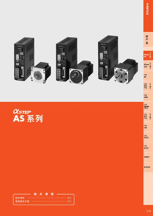
AS系列闭环控制步进马达组合产品规格一览表组合型号一览表电动机单体型号一览表驱动器型号一览表ASC系列闭环控制步进马达组合产品规格一览表组合型号一览表电动机单体型号一览表驱动器型号一览表RK系列5相步进马达组合产品规格一览表组合型号一览表电动机单体型号一览表驱动器型号一览表UPK · W系列5相步进马达组合具有东方步进马达的一般特性,为5相步进马达与专用驱动器的组合。
2. 具有易操作性的特点。
3. 种类齐全,有两百多种可供选择。
组合型号一览表电动机单体型号一览表驱动器型号一览表PMU系列5相步进马达组合具有东方步进马达的一般特性,为5相步进马达与专用驱动器的组合。
2. 安装尺寸为28*28mm,为小型,轻便型而推出的系列规格一览表组合型号一览表电动机单体型号一览表驱动器型号一览表UMK系列2相步进马达组合步进角为1.8°的2相步进马达与专用AC驱动器的组合。
2. 拥有内藏自动电流OFF,脉冲输入方式切换,步距角切换,过热输出逻辑切换功能,另配有用于检测机构原点时使用的激磁时序输出(TIMING)功能规格一览表组合型号一览表电动机单体型号一览表驱动器型号一览表CFKⅡ系列5相步进马达组合. 马达最小安装尺寸仅为20mm的微型设计,小型基板型驱动器,符合设备小型化的趋势。
2. 驱动器对应DC24~36V电压输入。
3. 低速情况下仍能保持低振荡的特性,适用于低速精密执行的场合。
规格一览表组合型号一览表电动机单体型号一览表驱动器型号一览表CRK系列5相步进马达组合1. 5相高性能步进马达与具备平滑驱动功能的小型,低振动,低噪音的驱动器的组合,2 .DC24V光耦合器输入,单/双脉冲输入规格。
3. CRK系列在保留前部品的优点情况下,推出追求定位精密的高分辨型规格一览表组合型号一览表电动机单体型号一览表驱动器型号一览表CSK系列5相步进马达组合1. 5相高性能步进马达与具备平滑驱动功能的小型,低振动,低噪音的驱动器的组合,2 .为东方步进马达的基本型组合。
RoHS-Compliant Stepping MotorsPK Series High-Torque TypeMotor Frame Size 20 mm (0.79 in.)"Features●●Small-Size and Light WeightWith a 20 mm (0.79 in.) frame size and 50 g (1.77 oz.) mass, this new motor is the smallest motor in the PK Series and is perfectly suited for applications with little space.<Actual Size>●●High-TorqueThis stepping motor utilizes Oriental Motor's high torque technology.30 mm (1.18 in.)20 mm (0.79 in.)20 mm (0.79 in.)• Mass50 g (1.77 oz.)for further specifications, dimensions, and speed-torque characteristics.Oriental Motor introduces a new stepping motor with a 20 mm (0.79 in.) frame size. This new motor offers a small and lightweight body combined with high torque technology."Speed – Torque Characteristics fs: Maximum Starting Frequency"Microstep Driver (Sold Separately)"Wiring Connection DiagramsPK213PDA , PK213PDB 4 Leads Bipolar ConnectionB PhaseA PhasePK213PA , PK213PB5 Leads Unipolar ConnectionA PhaseA PhaseB PhaseB PhasePK213PDA , PK213PDBT o r q u e [N ·m ]To r q u e [o z -i n ]1.510.5022.53.53Pulse Speed [kHz]Power Input 24 VDC Bipolar Constant Current Driver PK213PA , PK213PBPower Input 24 VDC Unipolar Constant Current Driver T o r q u e [N ·m ]10.51.522.5102030Pulse Speed [kHz]Full StepSpeed [r/min]T o r q u e [o z -i n ]"Dimensions Unit = mm (in.)Mass: 0.05 kg (0.11 lb.)PK213PD □: B612, PK213P □:B611●These dimensions are for the double shaft models. For the single shaft models,for PK213PDA , PK213PDB (20~40 VDC)for PK213PA , PK213PB (24 VDC)ORIENTAL MOTOR U.S.A. CORP .Technical Support Tel: 800-468-3982 7:30A.M.-7:00P .M. C.S.T. (M-F)E-mail:*****************************●●1,500 Products Same Day Shipping●Over 10,000 Products Shipped within 7 Days●●Free Sizing●2 Year Warranty ●Global SupportRBD215A-KCMD2109PPrinted in USA 10U 3T #401□20 mm (□0.79 in.)Step Angle 1.8°"SpecificationsNote: Driver operating current needs to be adjusted to 0.5 amps. Please see driver's operating manual for instructions. RBD215A-K (Setting 4), CMD2109P (Setting 6)。