Linux下的SPI设备驱动详解
- 格式:ppt
- 大小:2.27 MB
- 文档页数:23
Linux内核中SPI总线驱动分析本文主要有两个大的模块:一个是SPI总线驱动的分析(研究了具体实现的过程);另一个是SPI总线驱动的编写(不用研究具体的实现过程)。
1 SPI概述SPI是英语Serial Peripheral interface的缩写,顾名思义就是串行外围设备接口,是Motorola首先在其MC68HCXX系列处理器上定义的。
SPI接口主要应用在EEPROM,FLASH,实时时钟,AD转换器,还有数字信号处理器和数字信号解码器之间。
SPI是一种高速的,全双工,同步的通信总线,并且在芯片的管脚上只占用四根线,节约了芯片的管脚,同时为PCB的布局上节省空间,提供方便。
SPI的通信原理很简单,它以主从方式工作,这种模式通常有一个主设备和一个或多个从设备,需要4根线,事实上3根也可以。
也是所有基于SPI的设备共有的,它们是SDI(数据输入),SDO(数据输出),SCLK(时钟),CS(片选)。
MOSI(SDO):主器件数据输出,从器件数据输入。
MISO(SDI):主器件数据输入,从器件数据输出。
SCLK :时钟信号,由主器件产生。
CS:从器件使能信号,由主器件控制。
其中CS是控制芯片是否被选中的,也就是说只有片选信号为预先规定的使能信号时(高电位或低电位),对此芯片的操作才有效,这就允许在同一总线上连接多个SPI设备成为可能。
需要注意的是,在具体的应用中,当一条SPI总线上连接有多个设备时,SPI本身的CS 有可能被其他的GPIO脚代替,即每个设备的CS脚被连接到处理器端不同的GPIO,通过操作不同的GPIO口来控制具体的需要操作的SPI设备,减少各个SPI设备间的干扰。
SPI是串行通讯协议,也就是说数据是一位一位从MSB或者LSB开始传输的,这就是SCK 时钟线存在的原因,由SCK提供时钟脉冲,MISO、MOSI则基于此脉冲完成数据传输。
SPI 支持4-32bits的串行数据传输,支持MSB和LSB,每次数据传输时当从设备的大小端发生变化时需要重新设置SPI Master的大小端。

如何在Zynq 7000平台上使用Linux spidev.c驱动
在上一篇博客中,介绍了如何配置Vivado下的硬件工程、例化SPI硬件接口和如何使用petalinux加载Xilinx提供的SPI总线驱动,如果要通过SPI 控制外部器件,还需要添加SPI的设备驱动以实现SPI的对外控制逻辑。
在Linux内核的driver/spi目录下有许多外设的设备驱动可以参考,这篇博客主要介绍如何使用其中的spidev,c这个设备驱动来实现对外设的控制。
spidev是一个通用的SPI外设驱动,它提供了spi字符驱动的注册,并向上层应用程序提供了I/O控制接口,当我们仅需要利用SPI接口向外设发送和接收简单的控制序列时,可直接使用该驱动,下面介绍具体的使用方法。
一、在前一篇博客中,我们采用xilinx针对Zynq 7000处理器提供的spi-cadence.c驱动实现了芯片上SPI总线驱动的注册,接下来需要修改设备树文件以时我们的外设挂接在SPI总线下。
在petalinux工程的../subsystems/linux/configs/device-tree目录下找到zynq 相关的设备树文件,目录所包含的文件如下图所示。
Linux下的SPI总线驱动(一)2013-04-12 15:08:46分类:LINUX版权所有,转载请说明转自一.SPI理论介绍SPI总线全名,串行外围设备接口,是一种串行的主从接口,集成于很多微控制器内部。
和I2C使用2根线相比,SPI总线使用4根线:MOSI (SPI 总线主机输出/ 从机输入)、MISO (SPI总线主机输入/从机输出)、SCLK(时钟信号,由主设备产生)、CS(从设备使能信号,由主设备控制)。
由于SPI总线有专用的数据线用于数据的发送和接收,因此可以工作于全双工,当前市面上可以找到的SPI外围设备包括RF芯片、智能卡接口、E2PROM、RTC、触摸屏传感器、ADC。
SCLK信号线只由主设备控制,从设备不能控制信号线。
同样,在一个基于SPI的设备中,至少有一个主控设备。
这样传输的特点:这样的传输方式有一个优点,与普通的串行通讯不同,普通的串行通讯一次连续传送至少8位数据,而SPI允许数据一位一位的传送,甚至允许暂停,因为SCLK 时钟线由主控设备控制,当没有时钟跳变时,从设备不采集或传送数据。
也就是说,主设备通过对SCLK时钟线的控制可以完成对通讯的控制。
SPI还是一个数据交换协议:因为SPI的数据输入和输出线独立,所以允许同时完成数据的输入和输出。
不同的SPI 设备的实现方式不尽相同,主要是数据改变和采集的时间不同,在时钟信号上沿或下沿采集有不同定义,具体请参考相关器件的文档。
在点对点的通信中,SPI接口不需要进行寻址操作,且为全双工通信,显得简单高效。
在多个从设备的系统中,每个从设备需要独立的使能信号,硬件上比I2C 系统要稍微复杂一些。
二.SPI驱动移植我们下面将的驱动的移植是针对Mini2440的SPI驱动的移植Step1:在Linux Source Code中修改arch/arm/mach-s3c2440/文件,加入头文件:#include <linux/spi/>#include <../mach-s3c2410/include/mach/>然后加入如下代码:static struct spi_board_info s3c2410_spi0_board[] ={[0] = {.modalias = "spidev", us_num = 0, hip_select = 0, rq = IRQ_EINT9, ax_speed_hz = 500 * 1000,in_cs = S3C2410_GPG(2),.num_cs = 1, us_num = 0, pio_setup = s3c24xx_spi_gpiocfg_bus0_gpe11_12_13, odalias = "spidev",.bus_num = 1,.chip_select = 0,.irq = IRQ_EINT2,.max_speed_hz = 500 * 1000,}};static struct s3c2410_spi_info s3c2410_spi1_platdata = {.pin_cs = S3C2410_GPG(3),.num_cs = 1,.bus_num = 1,.gpio_setup = s3c24xx_spi_gpiocfg_bus1_gpg5_6_7,};Step2:在mini2440_devices[]平台数组中添加如下代码:&s3c_device_spi0,&s3c_device_spi1,Step3:最后在mini2440_machine_init函数中加入如下代码:&s3c2410_spi0_platdata;spi_register_board_info(s3c2410_spi0_board, ARRAY_SIZE(s3c2410_spi0_board)); &s3c2410_spi1_platdata;spi_register_board_info(s3c2410_spi1_board, ARRAY_SIZE(s3c2410_spi1_board)); Step4:最后需要修改arch/arm/plat-s3c24xx/KConfig文件找到config S3C24XX_SPI_BUS0_GPE11_GPE12_GPE13boolhelpSPI GPIO configuration code for BUS0 when connected toGPE11, GPE12 and GPE13.config S3C24XX_SPI_BUS1_GPG5_GPG6_GPG7boolhelpSPI GPIO configuration code for BUS 1 when connected toGPG5, GPG6 and GPG7.修改为config S3C24XX_SPI_BUS0_GPE11_GPE12_GPE13bool "S3C24XX_SPI_BUS0_GPE11_GPE12_GPE13"helpSPI GPIO configuration code for BUS0 when connected toGPE11, GPE12 and GPE13.config S3C24XX_SPI_BUS1_GPG5_GPG6_GPG7bool "S3C24XX_SPI_BUS1_GPG5_GPG6_GPG7"helpSPI GPIO configuration code for BUS 1 when connected toGPG5, GPG6 and GPG7.Step5:最后make menuconfig配置,选中System Type和SPI support相应文件Step6:执行make生成zInage,将编译好的内核导入开发板,并且编译测试程序运行即可。
L i n u x下S P I驱动测试程序-CAL-FENGHAI-(2020YEAR-YICAI)_JINGBIANLinux下的SPI总线驱动(一)2013-04-12 15:08:46分类:LINUX版权所有,转载请说明转自一.SPI理论介绍SPI总线全名,串行外围设备接口,是一种串行的主从接口,集成于很多微控制器内部。
和I2C使用2根线相比,SPI总线使用4根线:MOSI (SPI 总线主机输出/ 从机输入)、 MISO (SPI总线主机输入/从机输出)、SCLK(时钟信号,由主设备产生)、CS(从设备使能信号,由主设备控制)。
由于SPI总线有专用的数据线用于数据的发送和接收,因此可以工作于全双工,当前市面上可以找到的SPI外围设备包括RF芯片、智能卡接口、E2PROM、RTC、触摸屏传感器、ADC。
SCLK信号线只由主设备控制,从设备不能控制信号线。
同样,在一个基于SPI的设备中,至少有一个主控设备。
这样传输的特点:这样的传输方式有一个优点,与普通的串行通讯不同,普通的串行通讯一次连续传送至少8位数据,而SPI允许数据一位一位的传送,甚至允许暂停,因为SCLK 时钟线由主控设备控制,当没有时钟跳变时,从设备不采集或传送数据。
也就是说,主设备通过对SCLK时钟线的控制可以完成对通讯的控制。
SPI还是一个数据交换协议:因为SPI的数据输入和输出线独立,所以允许同时完成数据的输入和输出。
不同的SPI设备的实现方式不尽相同,主要是数据改变和采集的时间不同,在时钟信号上沿或下沿采集有不同定义,具体请参考相关器件的文档。
在点对点的通信中,SPI接口不需要进行寻址操作,且为全双工通信,显得简单高效。
在多个从设备的系统中,每个从设备需要独立的使能信号,硬件上比I2C 系统要稍微复杂一些。
二.SPI驱动移植我们下面将的驱动的移植是针对Mini2440的SPI驱动的移植Step1 :在Linux Source Code中修改arch/arm/mach-s3c2440/文件,加入头文件:#include <linux/spi/>#include <../mach-s3c2410/include/mach/>然后加入如下代码:static struct spi_board_info s3c2410_spi0_board[] ={[0] = {.modalias = "spidev", us_num = 0, hip_select = 0, rq = IRQ_EINT9, ax_speed_hz = 500 * 1000, in_cs = S3C2410_GPG(2),.num_cs = 1, us_num = 0, pio_setup = s3c24xx_spi_gpiocfg_bus0_gpe11_12_13, odalias = "spidev",.bus_num = 1,.chip_select = 0,.irq = IRQ_EINT2,.max_speed_hz = 500 * 1000,}};static struct s3c2410_spi_info s3c2410_spi1_platdata = {.pin_cs = S3C2410_GPG(3),.num_cs = 1,.bus_num = 1,.gpio_setup = s3c24xx_spi_gpiocfg_bus1_gpg5_6_7,};Step2:在mini2440_devices[]平台数组中添加如下代码:&s3c_device_spi0,&s3c_device_spi1,Step3:最后在mini2440_machine_init函数中加入如下代码:&s3c2410_spi0_platdata;spi_register_board_info(s3c2410_spi0_board, ARRAY_SIZE(s3c2410_spi0_board));&s3c2410_spi1_platdata;spi_register_board_info(s3c2410_spi1_board, ARRAY_SIZE(s3c2410_spi1_board));Step4:最后需要修改arch/arm/plat-s3c24xx/KConfig文件找到config S3C24XX_SPI_BUS0_GPE11_GPE12_GPE13boolhelpSPI GPIO configuration code for BUS0 when connected toGPE11, GPE12 and GPE13.config S3C24XX_SPI_BUS1_GPG5_GPG6_GPG7boolhelpSPI GPIO configuration code for BUS 1 when connected toGPG5, GPG6 and GPG7.修改为config S3C24XX_SPI_BUS0_GPE11_GPE12_GPE13bool "S3C24XX_SPI_BUS0_GPE11_GPE12_GPE13"helpSPI GPIO configuration code for BUS0 when connected toGPE11, GPE12 and GPE13.config S3C24XX_SPI_BUS1_GPG5_GPG6_GPG7bool "S3C24XX_SPI_BUS1_GPG5_GPG6_GPG7"helpSPI GPIO configuration code for BUS 1 when connected toGPG5, GPG6 and GPG7.Step5:最后make menuconfig配置,选中System Type和SPI support相应文件Step6:执行make生成zInage,将编译好的内核导入开发板,并且编译测试程序运行即可。
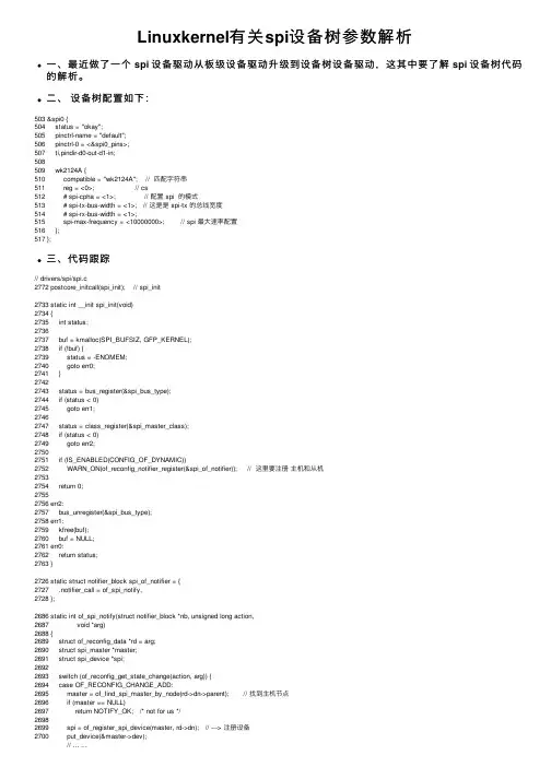
Linuxkernel有关spi设备树参数解析⼀、最近做了⼀个 spi 设备驱动从板级设备驱动升级到设备树设备驱动,这其中要了解 spi 设备树代码的解析。
⼆、设备树配置如下:503 &spi0 {504 status = "okay";505 pinctrl-name = "default";506 pinctrl-0 = <&spi0_pins>;507 ti,pindir-d0-out-d1-in;508509 wk2124A {510 compatible = "wk2124A"; // 匹配字符串511 reg = <0>; // cs512 # spi-cpha = <1>; // 配置 spi 的模式513 # spi-tx-bus-width = <1>; // 这是是 spi-tx 的总线宽度514 # spi-rx-bus-width = <1>;515 spi-max-frequency = <10000000>; // spi 最⼤速率配置516 };517 };三、代码跟踪// drivers/spi/spi.c2772 postcore_initcall(spi_init); // spi_init2733 static int __init spi_init(void)2734 {2735 int status;27362737 buf = kmalloc(SPI_BUFSIZ, GFP_KERNEL);2738 if (!buf) {2739 status = -ENOMEM;2740 goto err0;2741 }27422743 status = bus_register(&spi_bus_type);2744 if (status < 0)2745 goto err1;27462747 status = class_register(&spi_master_class);2748 if (status < 0)2749 goto err2;27502751 if (IS_ENABLED(CONFIG_OF_DYNAMIC))2752 WARN_ON(of_reconfig_notifier_register(&spi_of_notifier)); // 这⾥要注册主机和从机27532754 return 0;27552756 err2:2757 bus_unregister(&spi_bus_type);2758 err1:2759 kfree(buf);2760 buf = NULL;2761 err0:2762 return status;2763 }2726 static struct notifier_block spi_of_notifier = {2727 .notifier_call = of_spi_notify,2728 };2686 static int of_spi_notify(struct notifier_block *nb, unsigned long action,2687 void *arg)2688 {2689 struct of_reconfig_data *rd = arg;2690 struct spi_master *master;2691 struct spi_device *spi;26922693 switch (of_reconfig_get_state_change(action, arg)) {2694 case OF_RECONFIG_CHANGE_ADD:2695 master = of_find_spi_master_by_node(rd->dn->parent); // 找到主机节点2696 if (master == NULL)2697 return NOTIFY_OK; /* not for us */26982699 spi = of_register_spi_device(master, rd->dn); // ---> 注册设备2700 put_device(&master->dev);27222723 return NOTIFY_OK;2724 }1428 #if defined(CONFIG_OF)1429 static struct spi_device *1430 of_register_spi_device(struct spi_master *master, struct device_node *nc)1431 {1432 struct spi_device *spi;1433 int rc;1434 u32 value;14351436 /* Alloc an spi_device */1437 spi = spi_alloc_device(master);1438 if (!spi) {1439 dev_err(&master->dev, "spi_device alloc error for %s\n",1440 nc->full_name);1441 rc = -ENOMEM;1442 goto err_out;1443 }14441445 /* Select device driver */1446 rc = of_modalias_node(nc, spi->modalias, // 匹配到从机1447 sizeof(spi->modalias));1448 if (rc < 0) {1449 dev_err(&master->dev, "cannot find modalias for %s\n",1450 nc->full_name);1451 goto err_out;1452 }14531454 /* Device address */1455 rc = of_property_read_u32(nc, "reg", &value); // 设备节点 reg 表⽰ cs1456 if (rc) {1457 dev_err(&master->dev, "%s has no valid 'reg' property (%d)\n",1458 nc->full_name, rc);1459 goto err_out;1460 }1461 spi->chip_select = value;14621463 /* Mode (clock phase/polarity/etc.) */ // 选择 spi 的模式1464 if (of_find_property(nc, "spi-cpha", NULL))1465 spi->mode |= SPI_CPHA;1466 if (of_find_property(nc, "spi-cpol", NULL))1467 spi->mode |= SPI_CPOL;1468 if (of_find_property(nc, "spi-cs-high", NULL)) // 选择 spi cs 是⾼有效还是低有效 1469 spi->mode |= SPI_CS_HIGH;1470 if (of_find_property(nc, "spi-3wire", NULL))1471 spi->mode |= SPI_3WIRE;1472 if (of_find_property(nc, "spi-lsb-first", NULL))1473 spi->mode |= SPI_LSB_FIRST;14741475 /* Device DUAL/QUAD mode */ // 选择单线还是双线通道1476 if (!of_property_read_u32(nc, "spi-tx-bus-width", &value)) {1477 switch (value) {1478 case 1:1479 break;1480 case 2:1481 spi->mode |= SPI_TX_DUAL;1482 break;1483 case 4:1484 spi->mode |= SPI_TX_QUAD;1485 break;1486 default:1487 dev_warn(&master->dev,1488 "spi-tx-bus-width %d not supported\n",1489 value);1490 break;1491 }1492 }14931494 if (!of_property_read_u32(nc, "spi-rx-bus-width", &value)) {1495 switch (value) {1496 case 1:1497 break;1498 case 2:1499 spi->mode |= SPI_RX_DUAL;1500 break;1501 case 4:1502 spi->mode |= SPI_RX_QUAD;1503 break;1504 default:1505 dev_warn(&master->dev,1506 "spi-rx-bus-width %d not supported\n",1508 break;1509 }1510 }15111512 /* Device speed */ // 设备速度配置1513 rc = of_property_read_u32(nc, "spi-max-frequency", &value);1514 if (rc) {1515 dev_err(&master->dev, "%s has no valid 'spi-max-frequency' property (%d)\n", 1516 nc->full_name, rc);1517 goto err_out;1518 }1519 spi->max_speed_hz = value;15201521 /* Store a pointer to the node in the device structure */1522 of_node_get(nc);1523 spi->dev.of_node = nc; // 保存设备结构体15241525 /* Register the new device */1526 rc = spi_add_device(spi);1527 if (rc) {1528 dev_err(&master->dev, "spi_device register error %s\n",1529 nc->full_name);1530 goto err_out;1531 }15321533 return spi;15341535 err_out:1536 spi_dev_put(spi);1537 return ERR_PTR(rc);1538 }。
Linux下spi驱动开发(1)华清远见刘洪涛一、概述基于子系统去开发驱动程序已经是linux内核中普遍的做法了。
前面写过基于I2C子系统的驱动开发。
本文介绍另外一种常用总线SPI的开发方法。
SPI子系统的开发和I2C有很多的相似性,大家可以对比学习。
本主题分为两个部分叙述,第一部分介绍基于SPI子系统开发的理论框架;第二部分以华清远见教学平台FS_S5PC100上的M25P10芯片为例(内核版本2.6.29),编写一个SPI驱动程序实例。
二、SPI总线协议简介介绍驱动开发前,需要先熟悉下SPI通讯协议中的几个关键的地方,后面在编写驱动时,需要考虑相关因素。
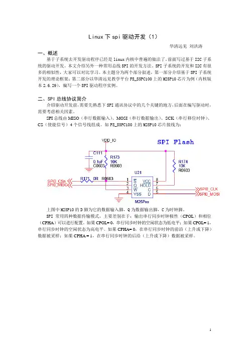
SPI总线由MISO(串行数据输入)、MOSI(串行数据输出)、SCK(串行移位时钟)、CS(使能信号)4个信号线组成。
如FS_S5PC100上的M25P10芯片接线为:上图中M25P10的D脚为它的数据输入脚,Q为数据输出脚,C为时钟脚。
SPI常用四种数据传输模式,主要差别在于:输出串行同步时钟极性(CPOL)和相位(CPHA)可以进行配置。
如果CPOL= 0,串行同步时钟的空闲状态为低电平;如果CPOL= 1,串行同步时钟的空闲状态为高电平。
如果CPHA= 0,在串行同步时钟的前沿(上升或下降)数据被采样;如果CPHA = 1,在串行同步时钟的后沿(上升或下降)数据被采样。
这四种模式中究竟选择哪种模式取决于设备。
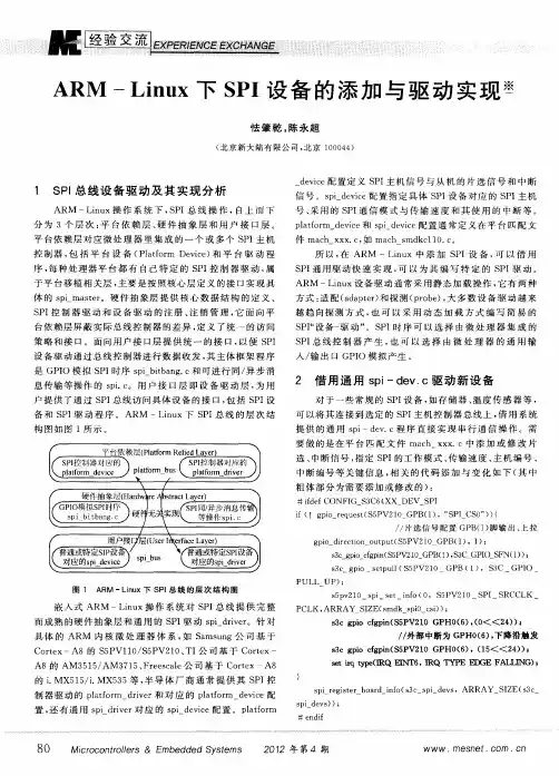
如M25P10的手册中明确它可以支持的两种模式为:CPOL=0 CPHA=0 和CPOL=1 CPHA=1三、linux下SPI驱动开发首先明确SPI驱动层次,如下图:SPI总线可理解为SPI控制器引出的总线1、Platform busP latform bus对应的结构是platform_bus_type,这个内核开始就定义好的。
我们不需要定义。
2、Platform_deviceSPI控制器对应platform_device的定义方式,同样以S5PC100中的SPI控制器为例,参看arch/arm/plat-s5pc1xx/dev-spi.c文件struct platform_device s3c_device_spi0 = {.name = "s3c64xx-spi", //名称,要和Platform_driver匹配.id = 0, //第0个控制器,S5PC100中有3个控制器.num_resources = ARRAY_SIZE(s5pc1xx_spi0_resource),//占用资源的种类.resource = s5pc1xx_spi0_resource,//指向资源结构数组的指针.dev = {.dma_mask = &spi_dmamask, //dma寻址范围.coherent_dma_mask = DMA_BIT_MASK(32), //可以通过关闭cache等措施保证一致性的dma寻址范围.platform_data = &s5pc1xx_spi0_pdata,//特殊的平台数据,参看后文},};static struct s3c64xx_spi_cntrlr_info s5pc1xx_spi0_pdata = {.cfg_gpio = s5pc1xx_spi_cfg_gpio, //用于控制器管脚的IO配置.fifo_lvl_mask = 0x7f,.rx_lvl_offset = 13,};static int s5pc1xx_spi_cfg_gpio(struct platform_device *pdev){s witch (pdev->id) {c ase 0:s3c_gpio_cfgpin(S5PC1XX_GPB(0), S5PC1XX_GPB0_SPI_MISO0);s3c_gpio_cfgpin(S5PC1XX_GPB(1), S5PC1XX_GPB1_SPI_CLK0);s3c_gpio_cfgpin(S5PC1XX_GPB(2), S5PC1XX_GPB2_SPI_MOSI0);s3c_gpio_setpull(S5PC1XX_GPB(0), S3C_GPIO_PULL_UP);s3c_gpio_setpull(S5PC1XX_GPB(1), S3C_GPIO_PULL_UP);s3c_gpio_setpull(S5PC1XX_GPB(2), S3C_GPIO_PULL_UP);break;c ase 1:s3c_gpio_cfgpin(S5PC1XX_GPB(4), S5PC1XX_GPB4_SPI_MISO1);s3c_gpio_cfgpin(S5PC1XX_GPB(5), S5PC1XX_GPB5_SPI_CLK1);s3c_gpio_cfgpin(S5PC1XX_GPB(6), S5PC1XX_GPB6_SPI_MOSI1);s3c_gpio_setpull(S5PC1XX_GPB(4), S3C_GPIO_PULL_UP);s3c_gpio_setpull(S5PC1XX_GPB(5), S3C_GPIO_PULL_UP);s3c_gpio_setpull(S5PC1XX_GPB(6), S3C_GPIO_PULL_UP);break;c ase 2:s3c_gpio_cfgpin(S5PC1XX_GPG3(0), S5PC1XX_GPG3_0_SPI_CLK2);s3c_gpio_cfgpin(S5PC1XX_GPG3(2), S5PC1XX_GPG3_2_SPI_MISO2);s3c_gpio_cfgpin(S5PC1XX_GPG3(3), S5PC1XX_GPG3_3_SPI_MOSI2);s3c_gpio_setpull(S5PC1XX_GPG3(0), S3C_GPIO_PULL_UP);s3c_gpio_setpull(S5PC1XX_GPG3(2), S3C_GPIO_PULL_UP);s3c_gpio_setpull(S5PC1XX_GPG3(3), S3C_GPIO_PULL_UP);break;d efault:dev_err(&pdev->dev, "Invalid SPI Controller number!");return -EINVAL;}3、Platform_driver再看platform_driver,参看drivers/spi/spi_s3c64xx.c文件static struct platform_driver s3c64xx_spi_driver = {.driver = {.name = "s3c64xx-spi", //名称,和platform_device对应.owner = THIS_MODULE,},.remove = s3c64xx_spi_remove,.suspend = s3c64xx_spi_suspend,.resume = s3c64xx_spi_resume,};platform_driver_probe(&s3c64xx_spi_driver, s3c64xx_spi_probe);//注册s3c64xx_spi_driver和平台中注册的platform_device匹配后,调用s3c64xx_spi_probe。

linuxSPI驱动——gpio模拟spi驱动(三)⼀:⾸先在我的平台注册platform_device,保证能让spi-gpio.c能执⾏到probe函数。
1: struct spi_gpio_platform_data {2: unsigned sck;3: unsigned mosi;4: unsigned miso;5:6: u16 num_chipselect;7: };1: //#define NCS GPIO_PB(2) //定义SS所对应的GPIO接⼝编号2: //#define SCLK GPIO_PB(0) //定义SCLK所对应的GPIO接⼝编号3: //#define MOSI GPIO_PB(4) //定义SCLK所对应的GPIO接⼝编号4: //#define MISO GPIO_PB(1)5: static struct spi_gpio_platform_data jz_spi_gpio_data = {6: .sck = GPIO_PB(0), //GPIO_SPI_SCK,7: .mosi = GPIO_PB(4), //GPIO_SPI_MOSI,8: .miso = GPIO_PB(1), //GPIO_SPI_MISO,9: .num_chipselect = 1,10: };11:12: struct platform_device jz_spi_gpio_device = {13: .name = "spi_gpio",14: .id = 0,15: .dev = {16: .platform_data = &jz_spi_gpio_data,17: },18: };注册platform device1: platform_device_register(&jz_spi_gpio_device);⼆:注册platform_driver在spi_gpio.c⾥⾯注册platform driver1: MODULE_ALIAS("platform:" DRIVER_NAME);2:3: static struct platform_driver spi_gpio_driver = {4: = DRIVER_NAME,5: .driver.owner = THIS_MODULE,6: .remove = __exit_p(spi_gpio_remove),7: };8:9: static int __init spi_gpio_init(void)10: {11: return platform_driver_probe(&spi_gpio_driver, spi_gpio_probe);12: }13: module_init(spi_gpio_init);14:15: static void __exit spi_gpio_exit(void)16: {17: platform_driver_unregister(&spi_gpio_driver);18: }19: module_exit(spi_gpio_exit);20:21:22: MODULE_DESCRIPTION("SPI master driver using generic bitbanged GPIO ");23: MODULE_AUTHOR("David Brownell");24: MODULE_LICENSE("GPL");三:具体算法分析1: struct spi_gpio {2: struct spi_bitbang bitbang; /* gpio 模拟spi算法相关的结构 */3: struct spi_gpio_platform_data pdata; /* spi platform data 对应模拟spi的四个gpio编号 */4: struct platform_device *pdev; /* 对应注册的 platform device */5: };1:2: static int __init spi_gpio_probe(struct platform_device *pdev)3: {4: int status;5: struct spi_master *master;6: struct spi_gpio *spi_gpio;7: struct spi_gpio_platform_data *pdata;8: u16 master_flags = 0;9:10: pdata = pdev->dev.platform_data; /* 存放spi的四根gpio */11: #ifdef GENERIC_BITBANG12: if (!pdata || !pdata->num_chipselect)13: return -ENODEV;14: #endif15:16: /* 申请注册四个gpio */17: status = spi_gpio_request(pdata, dev_name(&pdev->dev), &master_flags);18: if (status < 0) {19: return status;20: }21:22: /* alloc a spi master ,master->dev->p->driver_data = &master[1]*/23: master = spi_alloc_master(&pdev->dev, sizeof *spi_gpio);24: if (!master) {25: status = -ENOMEM;26: goto gpio_free;27: }28: /* spi_gpio指向⼀块空间, 即指向mstaer[1]29: pdev->dev->p->driver_data = spi_gpio;30: 初始化spi_gpio31: */32: spi_gpio = spi_master_get_devdata(master);33: platform_set_drvdata(pdev, spi_gpio);34:35: spi_gpio->pdev = pdev;36: if (pdata)37: spi_gpio->pdata = *pdata;38:39: master->flags = master_flags;40: master->bus_num = pdev->id;41: master->num_chipselect = SPI_N_CHIPSEL;42: master->setup = spi_gpio_setup; /* setup ⽐如cs引脚申请 */43: master->cleanup = spi_gpio_cleanup;44: /* spi_gpio->bitbang.master = master */45: spi_gpio->bitbang.master = spi_master_get(master);46: spi_gpio->bitbang.chipselect = spi_gpio_chipselect;47: /* spi_gpio->bitbang.txrx_word 数组函数四个元素指针,分别指向spi四种mode算法函数 */ 48: if ((master_flags & (SPI_MASTER_NO_TX | SPI_MASTER_NO_RX)) == 0) {49: spi_gpio->bitbang.txrx_word[SPI_MODE_0] = spi_gpio_txrx_word_mode0;50: spi_gpio->bitbang.txrx_word[SPI_MODE_1] = spi_gpio_txrx_word_mode1;51: spi_gpio->bitbang.txrx_word[SPI_MODE_2] = spi_gpio_txrx_word_mode2;52: spi_gpio->bitbang.txrx_word[SPI_MODE_3] = spi_gpio_txrx_word_mode3;53: } else {54: spi_gpio->bitbang.txrx_word[SPI_MODE_0] = spi_gpio_spec_txrx_word_mode0;55: spi_gpio->bitbang.txrx_word[SPI_MODE_1] = spi_gpio_spec_txrx_word_mode1;56: spi_gpio->bitbang.txrx_word[SPI_MODE_2] = spi_gpio_spec_txrx_word_mode2;57: spi_gpio->bitbang.txrx_word[SPI_MODE_3] = spi_gpio_spec_txrx_word_mode3;58: }59: /* spi_gpio->bitbang.setup_transfer初始化传输的bits_per_word和speed */60: spi_gpio->bitbang.setup_transfer = spi_bitbang_setup_transfer;61: spi_gpio->bitbang.flags = SPI_CS_HIGH;62: /* spi_gpio->bitbang相关算法接⼝初始化 */63: status = spi_bitbang_start(&spi_gpio->bitbang);64: if (status < 0) {65: spi_master_put(spi_gpio->bitbang.master);66: gpio_free:67: if (SPI_MISO_GPIO != SPI_GPIO_NO_MISO)68: gpio_free(SPI_MISO_GPIO);69: if (SPI_MOSI_GPIO != SPI_GPIO_NO_MOSI)70: gpio_free(SPI_MOSI_GPIO);71: gpio_free(SPI_SCK_GPIO);72: spi_master_put(master);73: }74:75: return status;76: }四:总之最终让spi_gpi0整个对象存放了整个gpio模拟spi的算法结构;⽽pdev->dev->p->driver_data = spi_gpio; platform device和 platform driver两者match结果是:root@CarRadio:/# ls /sys/bus/platform/devices/spi_gpio.0/driver modalias power spi0.0 spi_master subsystem ueventroot@CarRadio:/# ls /sys/bus/platform/devices/spi_gpio.0/driver/spi_gpio.0 uevent。
Linux驱动:SPI驱动编写要点题外话:⾯对成功和失败,⼀个⼈有没有“冠军之⼼”,直接影响他的表现。
⼏周前剖析了Linux SPI 驱动框架,算是明⽩个所以然,对于这么⼀个庞⼤的框架,并不是每⼀⾏代码都要⾃⼰去敲,因为前⼈已经把这个框架搭建好了,作为驱动开发者的我们只需要搞清楚哪⼀部分是需要⾃⼰修改或重新编写就OK了。
结合Linux内核⾯向对象的设计思想,SPI总的设计思路⼤概是这样的:第①处:内核中抽象了SPI控制器,让spi_master成为他的象征,他的实例化对象就是与硬⽣⽣的SPI控制器对应的,在Linux内核中习惯将集成到SOC上的控制器⽤假想的platform总线来进⾏管理,于是乎spi_master的实例化就得依靠platform_device和platform_driver来联⼿完成了。
细嚼慢咽:这⾥的platform_device就相当于是spi_master的静态描述:包括⼏号控制器、寄存器地址、引脚配置等等,把这些信息以“资源”的形式挂在platform_device上,等platform_driver找到命中注定的那个他之后就可以获得这个(静态描述)资源,probe中⽤这些资源就⽣出了spi_master实例对象。
这⼀系列流程前辈们都已经做好了,我们要做的就是将这静态描述platform_device修改成和⾃⼰SOC中的spi 控制器⼀致的特性即可。
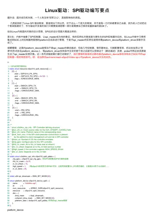
即:适当修改arch/arm/mach-s5pv210/dev-spi.c中platform_device涉及的成员。
1// SPI0的寄存器地址2static struct resource s5pv210_spi0_resource[] = {3 [0] = {4 .start = S5PV210_PA_SPI0,5 .end = S5PV210_PA_SPI0 + 0x100 - 1,6 .flags = IORESOURCE_MEM,7 },8 [1] = {9 .start = DMACH_SPI0_TX,10 .end = DMACH_SPI0_TX,11 .flags = IORESOURCE_DMA,12 },13 [2] = {14 .start = DMACH_SPI0_RX,15 .end = DMACH_SPI0_RX,16 .flags = IORESOURCE_DMA,17 },18 [3] = {19 .start = IRQ_SPI0,20 .end = IRQ_SPI0,21 .flags = IORESOURCE_IRQ,22 },23 };2425/**26 * struct s3c64xx_spi_info - SPI Controller defining structure27 * @src_clk_nr: Clock source index for the CLK_CFG[SPI_CLKSEL] field.28 * @src_clk_name: Platform name of the corresponding clock.29 * @clk_from_cmu: If the SPI clock/prescalar control block is present30 * by the platform's clock-management-unit and not in SPI controller.31 * @num_cs: Number of CS this controller emulates.32 * @cfg_gpio: Configure pins for this SPI controller.33 * @fifo_lvl_mask: All tx fifo_lvl fields start at offset-634 * @rx_lvl_offset: Depends on tx fifo_lvl field and bus number35 * @high_speed: If the controller supports HIGH_SPEED_EN bit36 * @tx_st_done: Depends on tx fifo_lvl field37*/38static struct s3c64xx_spi_info s5pv210_spi0_pdata = {39 .cfg_gpio = s5pv210_spi_cfg_gpio, //将GPIO配置成SPI0引脚的函数40 .fifo_lvl_mask = 0x1ff,41 .rx_lvl_offset = 15,42 .high_speed = 1, //看s5pv210的使⽤⼿册P901可知:这是⽤来配置CH_CFG寄存器的,主要是210⽤于从设备时......43 .tx_st_done = 25,44 };4546static u64 spi_dmamask = DMA_BIT_MASK(32);4748struct platform_device s5pv210_device_spi0 = {49 .name = "s3c64xx-spi",50 .id = 0,51 .num_resources = ARRAY_SIZE(s5pv210_spi0_resource),52 .resource = s5pv210_spi0_resource,53 .dev = {54 .dma_mask = &spi_dmamask,55 .coherent_dma_mask = DMA_BIT_MASK(32),56 .platform_data = &s5pv210_spi0_pdata,//特殊的spi_master数据57 },58 };platform_device第②处:添加/修改SPI外设“静态描述”的结构。
需要了解Linux下SPI从设备驱动的编写需要了解Linux下SPI从设备驱动的编写SPI(Serial Peripheral Interface) 是一个同步的四线制串行线,用于连接微控制器和传感器、存储器及外围设备。
三条信号线持有时钟信号(SCLK,经常在10MHz左右)和并行数据线带有“主出,从进(MOSI)”或是“主进,从出(MISO)”信号。
数据交换的时候有四种时钟模式,模式0和模式3是最经常使用的。
每个时钟周期将会传递数据进和出。
如果没有数据传递的话,时钟将不会循环。
SPI驱动分为两类:控制器驱动:它们通常内嵌于片上系统处理器,通常既支持主设备,又支持从设备。
这些驱动涉及硬件寄存器,可能使用DMA。
或它们使用GPIO引脚成为PIO bitbangers。
这部分通常会由特定的开发板提供商提供,不用自己写。
协议驱动:它们通过控制器驱动,以SPI连接的方式在主从设备之间传递信息。
这部分涉及具体的SPI从设备,通常需要自己编写。
那么特定的目标板如何让Linux 操控SPI设备?下面以AT91SAM9260系列CAN设备驱动为例,Linux内核版本为2.6.19。
本文不涉及控制器驱动分析。
board_info提供足够的信息使得系统正常工作而不需要芯片驱动加载[cpp] view plain copy在arch/arm/mach-at91rm9200/board-at91sam9260.c中有如下代码:#include#include…….static struct spi_board_info ek_spi_devices[] = {/* spi can ,add by mrz */#if defined(CONFIG_CAN_MCP2515) {.modalias = "mcp2515",.chip_select = 0,// .controller_data = AT91_PIN_PB3,。
今天折腾了一天的SPI设备的驱动加载,甚至动用了逻辑分析仪来查看spi总线的波形,主要包括两个SPI设备,at45db321d和 mcp2515,一个是串行的dataflash,一个是can总线设备芯片。
前者对于我们来说非常重要,我们可以借助该设备对uboot和kernel 以及根文件系统进行更新。
预备知识:设备和驱动是如何匹配的?系统的热插拔是如何实现的?首先一点,设备和驱动是严格区分的,设备是设备,驱动是驱动,设备通过struct device来定义,当然用户也可以将该结构体封装到自己定义的device 结构体中,例如,struct platform_device,这是我们采用platform_bus_type 总线的设备定义的结构体形式:include/linux/platform_device.h文件中:struct platform_device {const char* name;u32 id;struct device dev;u32 num_resources;struct resource* resource;};只要是9260的外围模块,就像IIC硬件控制器,SPI硬件控制器,都被完全的定义成这种结构体的格式,这种结构体主要包含了硬件资源和名称,硬件资源分为寄存器和IRQ两种。
platform_device通过向内核注册struct device dev这个结构体来告诉内核加载这个设备,方法就是 device_register(&platform_device->dev)内核不关心你使用的是platform_device还是spi_device,内核只关心你的struct device结构体,内核通过这个struct device结构体自然能够顺藤摸瓜找到你是platform_device还是spi_device,这就是linux最引以为傲的contian_of()大法。
2.6.18内核下已经添加了完整的spi子系统了,参考mtd的分析,将从下到上层,再从上到下层的对其进行分析。
以下先从下到上的进行分析:driver/spi下有两个底层相关的spi驱动程序:spi_s3c24xx.c和spi_s3c24xx_gpio.c其中spi_s3c24xx.c是基于s3c24xx下相应的spi接口的驱动程序,spi_s3c24xx_gpio.c允许用户指定3个gpio口,分别充当spi_clk、spi_mosi和spi_miso接口,模拟标准的spi总线。
s3c2410自带了两个spi接口(spi0和spi1),在此我只研究基于s3c2410下spi接口的驱动程序spi_s3c24xx.c。
首先从spi驱动的检测函数进行分析:static int s3c24xx_spi_probe(struct platform_device *pdev){struct s3c24xx_spi *hw;struct spi_master *master;struct spi_board_info *bi;struct resource *res;int err = 0;int i;/* pi_alloc_master函数申请了struct spi_master+struct s3c24xx_spi大小的数据, * spi_master_get_devdata和pi_master_get分别取出struct s3c24xx_spi 和struct spi_master结构指针*/master = spi_alloc_master(&pdev->dev, sizeof(struct s3c24xx_spi));if (master == NULL) {dev_err(&pdev->dev, "No memory for spi_master\n");err = -ENOMEM;goto err_nomem;}/* 填充struct spi_master结构*/hw = spi_master_get_devdata(master);memset(hw, 0, sizeof(struct s3c24xx_spi));hw->master = spi_master_get(master);hw->pdata = pdev->dev.platform_data;hw->dev = &pdev->dev;if (hw->pdata == NULL) {dev_err(&pdev->dev, "No platform data supplied\n");err = -ENOENT;goto err_no_pdata;}platform_set_drvdata(pdev, hw);//dev_set_drvdata(&pdev->dev, hw)init_completion(&hw->done);/* setup the state for the bitbang driver *//* 填充hw->bitbang结构(hw->bitbang结构充当一个中间层,相当与inputsystem的input_handle struct) */hw->bitbang.master = hw->master;hw->bitbang.setup_transfer = s3c24xx_spi_setupxfer;hw->bitbang.chipselect = s3c24xx_spi_chipsel;hw->bitbang.txrx_bufs = s3c24xx_spi_txrx;hw->bitbang.master->setup = s3c24xx_spi_setup;dev_dbg(hw->dev, "bitbang at %p\n", &hw->bitbang);/* find and map our resources *//* 申请spi所用到的资源:io、irq、时钟等*/res = platform_get_resource(pdev, IORESOURCE_MEM, 0);if (res == NULL) {dev_err(&pdev->dev, "Cannot get IORESOURCE_MEM\n");err = -ENOENT;goto err_no_iores;}hw->ioarea = request_mem_region(res->start, (res->end - res->start)+1,pdev->name);if (hw->ioarea == NULL) {dev_err(&pdev->dev, "Cannot reserve region\n");err = -ENXIO;goto err_no_iores;}hw->regs = ioremap(res->start, (res->end - res->start)+1);if (hw->regs == NULL) {dev_err(&pdev->dev, "Cannot map IO\n");err = -ENXIO;goto err_no_iomap;}hw->irq = platform_get_irq(pdev, 0);if (hw->irq dev, "No IRQ specified\n");err = -ENOENT;goto err_no_irq;}err = request_irq(hw->irq, s3c24xx_spi_irq, 0, pdev->name, hw);if (err) {dev_err(&pdev->dev, "Cannot claim IRQ\n");goto err_no_irq;}hw->clk = clk_get(&pdev->dev, "spi");if (IS_ERR(hw->clk)) {dev_err(&pdev->dev, "No clock for device\n");err = PTR_ERR(hw->clk);goto err_no_clk;}/* for the moment, permanently enable the clock */clk_enable(hw->clk);/* program defaults into the registers *//* 初始化spi相关的寄存器*/writeb(0xff, hw->regs + S3C2410_SPPRE);writeb(SPPIN_DEFAULT, hw->regs + S3C2410_SPPIN);writeb(SPCON_DEFAULT, hw->regs + S3C2410_SPCON);/* add by lfc */s3c2410_gpio_setpin(S3C2410_GPE13, 0);s3c2410_gpio_setpin(S3C2410_GPE12, 0);s3c2410_gpio_cfgpin(S3C2410_GPE13, S3C2410_GPE13_SPICLK0);s3c2410_gpio_cfgpin(S3C2410_GPE12, S3C2410_GPE12_SPIMOSI0);s3c2410_gpio_cfgpin(S3C2410_GPE11, S3C2410_GPE11_SPIMISO0);/* end add *//* setup any gpio we can *//* 片选*/if (!hw->pdata->set_cs) {s3c2410_gpio_setpin(hw->pdata->pin_cs, 1);s3c2410_gpio_cfgpin(hw->pdata->pin_cs, S3C2410_GPIO_OUTPUT);}/* register our spi controller *//* 最终通过调用spi_register_master来注册spi控制器(驱动) */err = spi_bitbang_start(&hw->bitbang);if (err) {dev_err(&pdev->dev, "Failed to register SPI master\n");goto err_register;}dev_dbg(hw->dev, "shutdown=%d\n", hw->bitbang.shutdown);/* register all the devices associated *//* 注册所用使用本spi驱动的设备*/bi = &hw->pdata->board_info[0];for (i = 0; i pdata->board_size; i++, bi++) {dev_info(hw->dev, "registering %s\n", bi->modalias);bi->controller_data = hw;spi_new_device(master, bi);}return 0;err_register:clk_disable(hw->clk);clk_put(hw->clk);err_no_clk:free_irq(hw->irq, hw);err_no_irq:iounmap(hw->regs);err_no_iomap:release_resource(hw->ioarea);kfree(hw->ioarea);err_no_iores:err_no_pdata:spi_master_put(hw->master);;err_nomem:return err;}/** spi_alloc_master - allocate SPI master controller* @dev: the controller, possibly using the platform_bus* @size: how much driver-private data to preallocate; the pointer to this* memory is in the class_data field of the returned class_device,* accessible with spi_master_get_devdata().** This call is used only by SPI master controller drivers, which are the* only ones directly touching chip registers. It's how they allocate* an spi_master structure, prior to calling spi_register_master().** This must be called from context that can sleep. It returns the SPI* master structure on success, else NULL.** The caller is responsible for assigning the bus number and initializing* the master's methods before calling spi_register_master(); and (after errors* adding the device) calling spi_master_put() to prevent a memory leak.*//*注释已经写得很清楚了,本函数旨在分配spi_master struct *其中,device为主控制设备,size为需要预分配的设备私有数据大小*该函数被spi主控制器驱动所调用,用于在调用spi_register_master注册主控制器前*分配spi_master struct,分配bus number和初始化主控制器的操作方法*注意在分配spi_master struct的时候多分配了大小为size的设备私有数据*并通过spi_master_set_devdata函数把其放到class_data field里,以后可以通过spi_master_get_devdata来访问*/struct spi_master * __init_or_modulespi_alloc_master(struct device *dev, unsigned size){struct spi_master *master;if (!dev)return NULL;master = kzalloc(size + sizeof *master, SLAB_KERNEL);if (!master)return NULL;class_device_initialize(&master->cdev);master->cdev.class = &spi_master_class;master->cdev.dev = get_device(dev);spi_master_set_devdata(master, &master[1]);return master;}/** spi_bitbang_start - start up a polled/bitbanging SPI master driver* @bitbang: driver handle** Caller should have zero-initialized all parts of the structure, and then* provided callbacks for chip selection and I/O loops. If the master has* a transfer method, its final step should call spi_bitbang_transfer; or,* that's the default if the transfer routine is not initialized. It should* also set up the bus number and number of chipselects.** For i/o loops, provide callbacks either per-word (for bitbanging, or for* hardware that basically exposes a shift register) or per-spi_transfer* (which takes better advantage of hardware like fifos or DMA engines).** Drivers using per-word I/O loops should use (or call) spi_bitbang_setup and* spi_bitbang_cleanup to handle those spi master methods. Those methods are* the defaults if the bitbang->txrx_bufs routine isn't initialized.** This routine registers the spi_master, which will process requests in a* dedicated task, keeping IRQs unblocked most of the time. To stop* processing those requests, call spi_bitbang_stop().*/int spi_bitbang_start(struct spi_bitbang *bitbang){int status;if (!bitbang->master || !bitbang->chipselect)return -EINV AL;/*bitbang_work * 初始化 a work,后面再create_singlethread_workqueue, * 等到有数据要传输的时候,在spi_bitbang_transfer函数中通过调用queue_work(bitbang->workqueue, &bitbang->work) * 把work扔进workqueue中调度运行 * 这是内核的一贯做法,在mmc/sd驱动中也是这样处理的^_^ */INIT_WORK(&bitbang->work, bitbang_work, bitbang);/* 初始化自旋锁和链表头,以后用到*/spin_lock_init(&bitbang->lock);spi_new_device INIT_LIST_HEAD(&bitbang->queue);if (!bitbang->master->transfer)bitbang->master->transfer = spi_bitbang_transfer;//spi数据的传输就是通过调用这个方法来实现的/* spi_s3c24xx.c驱动中有相应的txrx_bufs处理方法,在bitbang_work中被调用*/if (!bitbang->txrx_bufs) {bitbang->use_dma = 0;bitbang->txrx_bufs = spi_bitbang_bufs;if (!bitbang->master->setup) {if (!bitbang->setup_transfer)bitbang->setup_transfer =spi_bitbang_setup_transfer;bitbang->master->setup = spi_bitbang_setup;bitbang->master->cleanup = spi_bitbang_cleanup;}/* spi_s3c24xx.c驱动中有相应的setup处理方法,在稍后的spi_new_device 中被调用*/} else if (!bitbang->master->setup)return -EINV AL;/* this task is the only thing to touch the SPI bits */bitbang->busy = 0;/* 创建工作者进程*/bitbang->workqueue = create_singlethread_workqueue(bitbang->master->cdev.dev->bus_id);if (bitbang->workqueue == NULL) {status = -EBUSY;goto err1;}/* driver may get busy before register() returns, especially* if someone registered boardinfo for devices*/status = spi_register_master(bitbang->master);if (status workqueue);err1:return status;}/*** spi_register_master - register SPI master controller* @master: initialized master, originally from spi_alloc_master()** SPI master controllers connect to their drivers using some non-SPI bus,* such as the platform bus. The final stage of probe() in that code* includes calling spi_register_master() to hook up to this SPI bus glue.** SPI controllers use board specific (often SOC specific) bus numbers,* and board-specific addressing for SPI devices combines those numbers* with chip select numbers. Since SPI does not directly support dynamic* device identification, boards need configuration tables telling which* chip is at which address.** This must be called from context that can sleep. It returns zero on* success, else a negative error code (dropping the master's refcount).* After a successful return, the caller is responsible for calling* spi_unregister_master().*/int __init_or_modulespi_register_master(struct spi_master *master){static atomic_t dyn_bus_id = ATOMIC_INIT((1cdev.dev;int status = -ENODEV;int dynamic = 0;if (!dev)return -ENODEV;/* convention: dynamically assigned bus IDs count down from the max */if (master->bus_num bus_num = atomic_dec_return(&dyn_bus_id);dynamic = 1;}/* register the device, then userspace will see it.* registration fails if the bus ID is in use.*/snprintf(master->cdev.class_id, sizeof master->cdev.class_id,"spi%u", master->bus_num);status = class_device_add(&master->cdev);//注册设备if (status cdev.class_id,dynamic ? " (dynamic)" : "");/* populate children from any spi device tables */scan_boardinfo(master);status = 0;done:return status;}/* FIXME someone should add support for a __setup("spi", ...) that* creates board info from kernel command lines*//* * scan board_list for spi_board_info which is registered by spi_register_board_info * 很可惜,s3c24xx的spi驱动中不支持spi_register_board_info这种标准方式注册方式,而是直接调用spi_new_device内部函数*/static void __init_or_modulescan_boardinfo(struct spi_master *master){struct boardinfo *bi;struct device *dev = master->cdev.dev;down(&board_lock);list_for_each_entry(bi, &board_list, list) {struct spi_board_info *chip = bi->board_info;unsigned n;for (n = bi->n_board_info; n > 0; n--, chip++) {if (chip->bus_num != master->bus_num)continue;/* some controllers only have one chip, so they* might not use chipselects. otherwise, the* chipselects are numbered 0..max.*/if (chip->chip_select >= master->num_chipselect&& master->num_chipselect) {dev_dbg(dev, "cs%d > max %d\n",chip->chip_select,master->num_chipselect);continue;}(void) spi_new_device(master, chip);}}up(&board_lock);}/** Board-specific early init code calls this (probably during arch_initcall)* with segments of the SPI device table. Any device nodes are created later, * after the relevant parent SPI controller (bus_num) is defined. We keep* this table of devices forever, so that reloading a controller driver will* not make Linux forget about these hard-wired devices.** Other code can also call this, e.g. a particular add-on board might provide * SPI devices through its expansion connector, so code initializing that board * would naturally declare its SPI devices.** The board info passed can safely be __initdata ... but be careful of* any embedded pointers (platform_data, etc), they're copied as-is.*/int __initspi_register_board_info(struct spi_board_info const *info, unsigned n){struct boardinfo *bi;bi = kmalloc(sizeof(*bi) + n * sizeof *info, GFP_KERNEL);if (!bi)return -ENOMEM;bi->n_board_info = n;memcpy(bi->board_info, info, n * sizeof *info);down(&board_lock);list_add_tail(&bi->list, &board_list);up(&board_lock);return 0;}/* On typical mainboards, this is purely internal; and it's not needed* after board init creates the hard-wired devices. Some development* platforms may not be able to use spi_register_board_info though, and* this is exported so that for example a USB or parport based adapter* driver could add devices (which it would learn about out-of-band).*/struct spi_device *__init_or_modulespi_new_device(struct spi_master *master, struct spi_board_info *chip){struct spi_device *proxy;//这个结构很重要,以后就是通过这个结构来操作实际的spi设备的struct device *dev = master->cdev.dev;int status;/* NOTE: caller did any chip->bus_num checks necessary */if (!spi_master_get(master))return NULL;proxy = kzalloc(sizeof *proxy, GFP_KERNEL);if (!proxy) {dev_err(dev, "can't alloc dev for cs%d\n",chip->chip_select);goto fail;}/* 初始化spi_device 结构各成员*/proxy->master = master;proxy->chip_select = chip->chip_select;proxy->max_speed_hz = chip->max_speed_hz;proxy->mode = chip->mode;proxy->irq = chip->irq;proxy->modalias = chip->modalias;snprintf(proxy->dev.bus_id, sizeof proxy->dev.bus_id,"%s.%u", master->cdev.class_id,chip->chip_select);proxy->dev.parent = dev;proxy->dev.bus = &spi_bus_type;proxy->dev.platform_data = (void *) chip->platform_data;proxy->controller_data = chip->controller_data;proxy->controller_state = NULL;proxy->dev.release = spidev_release;/* drivers may modify this default i/o setup *//* 调用master->setup(即s3c24xx_spi_setup)函数初始化spi设备*/ status = master->setup(proxy);if (status dev.bus_id, status);goto fail;}/* driver core catches callers that misbehave by defining* devices that already exist.*/status = device_register(&proxy->dev);//真正注册原始设备if (status dev.bus_id, status);goto fail;}dev_dbg(dev, "registered child %s\n", proxy->dev.bus_id);return proxy;fail:spi_master_put(master);kfree(proxy);return NULL;}static int s3c24xx_spi_setup(struct spi_device *spi){int ret;/* 进行一些检查性操作*/if (!spi->bits_per_word)spi->bits_per_word = 8;if ((spi->mode & SPI_LSB_FIRST) != 0)return -EINV AL;ret = s3c24xx_spi_setupxfer(spi, NULL);if (ret dev, "setupxfer returned %d\n", ret);return ret;}dev_dbg(&spi->dev, "%s: mode %d, %u bpw, %d hz\n",__FUNCTION__, spi->mode, spi->bits_per_word,spi->max_speed_hz);return 0;}static int s3c24xx_spi_setupxfer(struct spi_device *spi,struct spi_transfer *t){struct s3c24xx_spi *hw = to_hw(spi);unsigned int bpw;unsigned int hz;unsigned int div;bpw = t ? t->bits_per_word : spi->bits_per_word;hz = t ? t->speed_hz : spi->max_speed_hz;if (bpw != 8) {dev_err(&spi->dev, "invalid bits-per-word (%d)\n", bpw);return -EINV AL;}div = clk_get_rate(hw->clk) / hz;/* is clk = pclk / (2 * (pre+1)), or is it* clk = (pclk * 2) / ( pre + 1) */div = (div / 2) - 1;//求出预分频值if (div 255)div = 255;dev_dbg(&spi->dev, "setting pre-scaler to %d (hz %d)\n", div, hz);writeb(div, hw->regs + S3C2410_SPPRE);//设置预分频值spin_lock(&hw->bitbang.lock);if (!hw->bitbang.busy) {hw->bitbang.chipselect(spi, BITBANG_CS_INACTIVE);//修改时钟,先禁用spi/* need to ndelay for 0.5 clocktick ? */}spin_unlock(&hw->bitbang.lock);return 0;}static void s3c24xx_spi_chipsel(struct spi_device *spi, int value){struct s3c24xx_spi *hw = to_hw(spi);unsigned int cspol = spi->mode & SPI_CS_HIGH ? 1 : 0;unsigned int spcon;switch (value) {case BITBANG_CS_INACTIVE:/* 禁用spi(禁用片选) */if (hw->pdata->set_cs)hw->pdata->set_cs(hw->pdata, value, cspol);elses3c2410_gpio_setpin(hw->pdata->pin_cs, cspol ^ 1);break;case BITBANG_CS_ACTIVE:/* * 启用spi:根据需要设置寄存器并启用使能片选 * (如果spi_board_info中没有设置相应的mode选项的话,那就只能使用默认值SPPIN_DEFAULT和SPCON_DEFAULT了) */spcon = readb(hw->regs + S3C2410_SPCON);if (spi->mode & SPI_CPHA)spcon |= S3C2410_SPCON_CPHA_FMTB;elsespcon &= ~S3C2410_SPCON_CPHA_FMTB;if (spi->mode & SPI_CPOL)spcon |= S3C2410_SPCON_CPOL_HIGH;elsespcon &= ~S3C2410_SPCON_CPOL_HIGH;spcon |= S3C2410_SPCON_ENSCK;/* write new configration */writeb(spcon, hw->regs + S3C2410_SPCON);if (hw->pdata->set_cs)hw->pdata->set_cs(hw->pdata, value, cspol);elses3c2410_gpio_setpin(hw->pdata->pin_cs, cspol);break;}}好了,至此spi主控制器(驱动)和板上spi设备注册完毕,以后要使用spi来传输数据的话,只要先获得spi设备结构,然后就可以利用它来和spi驱动打交道了(就好像你要操作一个文件,先要获取文件句柄一样,明白吧^_^)上文从下到上的介绍了spi子系统,现在反过来从上到下的来介绍spi子系统的使用:int spi_register_driver(struct spi_driver *sdrv){sdrv->driver.bus = &spi_bus_type;if (sdrv->probe)sdrv->driver.probe = spi_drv_probe;if (sdrv->remove)sdrv->driver.remove = spi_drv_remove;if (sdrv->shutdown)sdrv->driver.shutdown = spi_drv_shutdown;return driver_register(&sdrv->driver);}2.6内核的典型做法,不直接使用原始设备驱动,而是使用包装后的抽象设备驱动spi_driver,间接与原始设备驱动建立联系,并最终通过调用driver_register来注册原始设备驱动(要充分理解2.6内核的抽象化思想)。
linux设备驱动spi详解5-应⽤到驱动的完整流程所有的应⽤程序使⽤dev/⽬录下创建的设备,这些字符设备的操作函数集在⽂件spidev.c中实现。
1static const struct file_operations spidev_fops = {2 .owner = THIS_MODULE,3/* REVISIT switch to aio primitives, so that userspace4 * gets more complete API coverage. It'll simplify things5 * too, except for the locking.6*/7 .write = spidev_write,8 .read = spidev_read,9 .unlocked_ioctl = spidev_ioctl,10 .open = spidev_open,11 .release = spidev_release,12 };1 spidev_ioctl函数以上是所有应⽤程序所能够做的所有操作,由此开始追踪spi 驱动程序的完整执⾏流程其中,最重要的就是ioctl, 从这⾥开始先重点剖析ioctl函数1 spidev_ioctl(struct file *filp, unsigned int cmd, unsigned long arg)2 {3int err = 0;4int retval = 0;5struct spidev_data *spidev;6struct spi_device *spi;7 u32 tmp;8 unsigned n_ioc;9struct spi_ioc_transfer *ioc;10//ioctl cmd 检查11/* Check type and command number */12if (_IOC_TYPE(cmd) != SPI_IOC_MAGIC)13return -ENOTTY;1415/* Check access direction once here; don't repeat below.16 * IOC_DIR is from the user perspective, while access_ok is17 * from the kernel perspective; so they look reversed.18*/19if (_IOC_DIR(cmd) & _IOC_READ)20 err = !access_ok(VERIFY_WRITE,21 (void __user *)arg, _IOC_SIZE(cmd));22if (err == 0 && _IOC_DIR(cmd) & _IOC_WRITE)23 err = !access_ok(VERIFY_READ,24 (void __user *)arg, _IOC_SIZE(cmd));25if (err)26return -EFAULT;2728/* guard against device removal before, or while,29 * we issue this ioctl.30*/31//通过以下⽅式获取spi_device-----spi(是之后操作的基础)32 spidev = filp->private_data;33 spin_lock_irq(&spidev->spi_lock);34 spi = spi_dev_get(spidev->spi);35 spin_unlock_irq(&spidev->spi_lock);3637if (spi == NULL)38return -ESHUTDOWN;3940/* use the buffer lock here for triple duty:41 * - prevent I/O (from us) so calling spi_setup() is safe;42 * - prevent concurrent SPI_IOC_WR_* from morphing43 * data fields while SPI_IOC_RD_* reads them;44 * - SPI_IOC_MESSAGE needs the buffer locked "normally".45*/46 mutex_lock(&spidev->buf_lock);47//以上是进⾏check,检查命令有效性,以及进⾏初始化数据,这⾥不在多做说明48switch (cmd) {49/* read requests */50case SPI_IOC_RD_MODE://获取模式信息,将信息发送给⽤户51 retval = __put_user(spi->mode & SPI_MODE_MASK,52 (__u8 __user *)arg);53break;54case SPI_IOC_RD_LSB_FIRST://获取spi最低有效位55 retval = __put_user((spi->mode & SPI_LSB_FIRST) ? 1 : 0,56 (__u8 __user *)arg);57break;58case SPI_IOC_RD_BITS_PER_WORD:59 retval = __put_user(spi->bits_per_word, (__u8 __user *)arg);61case SPI_IOC_RD_MAX_SPEED_HZ:62 retval = __put_user(spi->max_speed_hz, (__u32 __user *)arg);63break;6465/* write requests */66case SPI_IOC_WR_MODE://设置数据传输模式,这⾥只是把设置的数据保存在spi 中,但并没有对spi device做任何操作,对spi device的操作⼀并在最后进⾏ 67 retval = __get_user(tmp, (u8 __user *)arg);68if (retval == 0) {69 u8 save = spi->mode;7071if (tmp & ~SPI_MODE_MASK) {72 retval = -EINVAL;73break;74 }7576 tmp |= spi->mode & ~SPI_MODE_MASK;77 spi->mode = (u8)tmp;78 retval = spi_setup(spi);79if (retval < 0)80 spi->mode = save;81else82 dev_dbg(&spi->dev, "spi mode %02xn", tmp);83 }84break;85case SPI_IOC_WR_LSB_FIRST://设置设置spi写最低有效位,同上86 retval = __get_user(tmp, (__u8 __user *)arg);87if (retval == 0) {88 u8 save = spi->mode;8990if (tmp)91 spi->mode |= SPI_LSB_FIRST;92else93 spi->mode &= ~SPI_LSB_FIRST;94 retval = spi_setup(spi);95if (retval < 0)96 spi->mode = save;97else98 dev_dbg(&spi->dev, "%csb firstn",99 tmp ? 'l' : 'm');100 }101break;102case SPI_IOC_WR_BITS_PER_WORD://设置spi写每个字含多个个位,同上103 retval = __get_user(tmp, (__u8 __user *)arg);104if (retval == 0) {105 u8 save = spi->bits_per_word;106107 spi->bits_per_word = tmp;108 retval = spi_setup(spi);109if (retval < 0)110 spi->bits_per_word = save;111else112 dev_dbg(&spi->dev, "%d bits per wordn", tmp);113 }114break;115case SPI_IOC_WR_MAX_SPEED_HZ://设置spi写最⼤速率,同上116 retval = __get_user(tmp, (__u32 __user *)arg);117if (retval == 0) {118 u32 save = spi->max_speed_hz;119120 spi->max_speed_hz = tmp;121 retval = spi_setup(spi);122if (retval < 0)123 spi->max_speed_hz = save;124else125 dev_dbg(&spi->dev, "%d Hz (max)n", tmp);126 }127break;128129default:130/* segmented and/or full-duplex I/O request */131if (_IOC_NR(cmd) != _IOC_NR(SPI_IOC_MESSAGE(0))//查看是否为数据write命令132 || _IOC_DIR(cmd) != _IOC_WRITE) {133 retval = -ENOTTY;134break;135 }136//pay more time on understanding below method137 tmp = _IOC_SIZE(cmd);//从命令参数中解析出⽤户数据⼤⼩138if ((tmp % sizeof(struct spi_ioc_transfer)) != 0) {//数据⼤⼩必须是struct spi_ioc_transfer的整数倍139 retval = -EINVAL;140break;141 }142 n_ioc = tmp / sizeof(struct spi_ioc_transfer);//将要传输的数据分成n个传输数据段143if (n_ioc == 0)145146/* copy into scratch area */147 ioc = kmalloc(tmp, GFP_KERNEL);//获取n个数据段的数据管理结构体的内存空间148if (!ioc) {149 retval = -ENOMEM;150break;151 }152if (__copy_from_user(ioc, (void __user *)arg, tmp)) {//从⽤户空间获取数据管理结构体的初始化值153 kfree(ioc);154 retval = -EFAULT;155break;156 }157158/* translate to spi_message, execute */159 retval = spidev_message(spidev, ioc, n_ioc);//数据传输,这是整个流程中的核⼼160 kfree(ioc);161break;162 }163164 mutex_unlock(&spidev->buf_lock);165 spi_dev_put(spi);166return retval;167 }通过调⽤函数spi->master->setup()来设置SPI模式。
Linux下基于MCP2515的CAN总线驱动程序设计随着物联网技术的不断发展,嵌入式系统和传感器网络在各领域得到了广泛应用。
在这些系统中,可以利用CAN总线进行数据通信,实现设备之间的无缝连接和数据交换。
本文将介绍一种基于Linux系统的MCP2515的CAN总线驱动程序设计。
一、MCP2515MCP2515是一种SPI接口的CAN控制器,具有很高的集成度和灵活性。
它包括CAN控制器、CAN收发器和SPI接口。
MCP2515通过SPI接口与主控制器进行通信,可以实现CAN 节点之间的数据通信。
此外,MCP2515还支持各种标准和扩展CAN帧格式。
二、CAN总线驱动程序设计1、编写SPI驱动程序由于MCP2515是通过SPI接口与主控制器进行通信的,所以需要编写SPI驱动程序。
在Linux系统中,可以通过SPI驱动程序来实现与MCP2515的通信。
SPI口的驱动程序可能会因为系统的不同而有所差异。
2、编写CAN驱动程序在Linux中,可以使用SocketCAN实现CAN总线驱动程序。
SocketCAN是Linux内核自带的CAN协议栈,提供了丰富的API和工具,方便开发者开发CAN应用程序。
在编写CAN驱动程序时,需要先对MCP2515进行配置,设置CAN通信参数以及滤波器参数。
通过SocketCAN提供的API函数可以实现CAN帧的发送和接收,从而实现数据通信。
三、示例代码以下是基于Linux系统的MCP2515的CAN总线驱动程序设计的示例代码:1、SPI驱动程序可以通过spidev接口进行使用:```#include <stdio.h>#include <stdlib.h>#include <fcntl.h>#include <unistd.h>#include <sys/ioctl.h>#include <linux/spi/spidev.h>#define SPI_DEVICE "/dev/spidev0.0"int spi_fd;int spi_open(){if ((spi_fd = open(SPI_DEVICE, O_RDWR)) < 0){printf("Cannot open %s\n", SPI_DEVICE);return -1;}int mode = SPI_MODE_0;int bits_per_word = 8;int speed = 1000000;if (ioctl(spi_fd, SPI_IOC_WR_MODE, &mode) < 0)return -1;if (ioctl(spi_fd, SPI_IOC_WR_BITS_PER_WORD,&bits_per_word) < 0)return -1;if (ioctl(spi_fd, SPI_IOC_WR_MAX_SPEED_HZ, &speed) < 0) return -1;return 0;}int spi_close(){close(spi_fd);return 0;}int spi_write_read(char *buf, int len, int speed_hz){int ret;struct spi_ioc_transfer transfer;transfer.tx_buf = (unsigned long)buf;transfer.rx_buf = (unsigned long)buf;transfer.len = len;transfer.speed_hz = speed_hz;transfer.bits_per_word = 8;transfer.delay_usecs = 0;ret = ioctl(spi_fd, SPI_IOC_MESSAGE(1), &transfer); return ret;}```2、CAN驱动程序可以通过SocketCAN提供的API函数实现:```#include <stdio.h>#include <stdlib.h>#include <fcntl.h>#include <sys/ioctl.h>#include <net/if.h>#include <linux/can.h>#include <linux/can/raw.h>int can_fd;int can_init(const char *ifname){if ((can_fd = socket(PF_CAN, SOCK_RAW, CAN_RAW)) < 0) {perror("Socket error\n");return -1;}struct ifreq ifr;strcpy(ifr.ifr_name, ifname);if (ioctl(can_fd, SIOCGIFINDEX, &ifr) < 0){perror("SIOCGIFINDEX error\n");return -1;}struct sockaddr_can addr;memset(&addr, 0, sizeof(addr));addr.can_family = AF_CAN;addr.can_ifindex = ifr.ifr_ifindex;if (bind(can_fd, (struct sockaddr *)&addr, sizeof(addr)) < 0){perror("Bind error\n");return -1;}return 0;}int can_deinit(){close(can_fd);return 0;}int can_send(unsigned int id, unsigned char *data, unsigned char len){struct can_frame frame;memset(&frame, 0, sizeof(struct can_frame));frame.can_id = id;frame.can_dlc = len;memcpy(frame.data, data, len);int ret = write(can_fd, &frame, sizeof(struct can_frame));if (ret != sizeof(struct can_frame)){perror("Write error\n");return -1;}return 0;}int can_recv(unsigned int *id, unsigned char *data, unsigned char *len){struct can_frame frame;int ret = read(can_fd, &frame, sizeof(struct can_frame));if (ret < 0){perror("Read error\n");return -1;}*id = frame.can_id;memcpy(data, frame.data, frame.can_dlc);*len = frame.can_dlc;return 0;}```四、结语在Linux系统中,基于MCP2515的CAN总线驱动程序设计相对较为简单,可以利用SocketCAN实现。