成都圣玛特AS使用说明书.doc
- 格式:pdf
- 大小:12.69 MB
- 文档页数:53

AS自动进样器操作手册戴安中国有限公司技术服务中心2005.10目 录1.简介 ﹒﹒﹒﹒﹒﹒﹒﹒﹒﹒﹒﹒ 22.仪器介绍 ﹒﹒﹒﹒﹒﹒﹒﹒﹒﹒﹒﹒ 33.操作 ﹒﹒﹒﹒﹒﹒﹒﹒﹒﹒﹒﹒ 154.故障指南 ﹒﹒﹒﹒﹒﹒﹒﹒﹒﹒﹒﹒ 315.维修 ﹒﹒﹒﹒﹒﹒﹒﹒﹒﹒﹒﹒ 42 附录A技术指标 ﹒﹒﹒﹒﹒﹒﹒﹒﹒﹒﹒﹒ 57 附录B安装 ﹒﹒﹒﹒﹒﹒﹒﹒﹒﹒﹒﹒ 58 附录C显示屏幕 ﹒﹒﹒﹒﹒﹒﹒﹒﹒﹒﹒﹒ 681. 简介AS自动进样器的进样量在1.0 ~ 99.9μL之间时,进样体积可以0.1μL变化;进样量在100 ~ 1000μL之间时,进样体积可以1μL变化。
每种进样瓶均可连续进样99次。
如果安装了5mL的注射器,进样体积可以在1 ~ 4700μL之间调节;同步进样时,进样体积在1000 ~ 4700μL之间调节。
如果安装了10mL的注射器,进样体积可以在1 ~ 8000μL之间调节;同步进样时,进样体积可以在1000 ~ 8000μL之间调节。
注意:安装5或10mL的注射器时,必须安装8.2mL针头附件。
正常进样:向一个单系统的定量环输送样品。
浓缩进样:向一个单系统的超低压浓缩柱输送样品。
同步进样:向两个系统的定量环同时输送样品。
顺序进样:分别向两个系统的定量环输送不同样品。
顺序浓缩进样:分别向两个系统的超低压浓缩柱输送不同样品。
AS有两种样品托盘可供选择:10mL托盘可以容纳49个样品瓶(标准配置);1.5mL托盘可以容纳100个样品瓶(具有加热/冷却功能的样品托盘仅与1.5mL样品瓶匹配)。
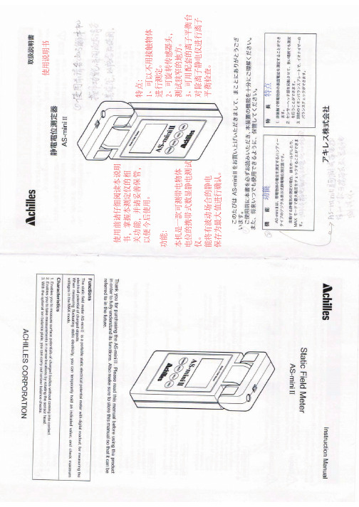
2. 仪器介绍2.1 概述(见图1)图1. AS外型图控制面板── 包含液晶显示屏(亮度可以调节)和薄膜按键; 主机 ── 包含样品瓶及托盘、进样阀和机械臂等;注射器和溶剂瓶 ── 放置在AS顶部;电源开关 ── 在AS的左下角。
2.2 控制面板(见图2)光标移动和操作参数的选择需要进行键盘操作。


CYT-120-1 CONVEYOR TOASTER INSTRUCTION MANUALI N S T R U C T I O N M A N U ALWARNINGS• Do not touch any hot surfaces• Do not immerse unit, cord or plug in liquid at any time• Unplug cord from outlet when not in use and before cleaning • Plug only into a 3-hole grounded electrical outlet • Do not operate unattended• Do not use this unit for anything other than intended use • Do not use outdoors • Always use on a fi rm, dry and level surface at least 12” from walls or any other obstruction• Do not use if unit has a damaged cord or plug, in the event the appliance malfunctions, or has been damaged in any manner• Keep children and animals away from unit• Any incorrect installation, alterations, adjustments and/or improper maintenance can lead to property loss and injury. All repairs should be done by authorized professionals only• Ensure that the designated power supply is adequate for continual usage and the voltage is correct INSTALLATION1. Remove the unit and all packing materials from the carton and remove protective covering fromthe unit and parts.2. Remove tape from the discharge chute, crumb tray and toast collector pan.3. If the unit is not level, use the feet to level.4. The toast feed ramp is installed at the factory and can be used in two positions: -When in the upright position, the toaster is set for automatic feed. Bread products enterthe toaster by placing them on the feed ramp and releasing.-For manual feeding of product, tip the feed ramp until it rests on top of the unit. In this positionbread products can be manually loaded by placing them directly on the conveyor belt.5. Install toast crumb tray directly below the conveyor belt and below the stop pins. Insert untilthe front of the crumb tray meets the stop pins.TO USE1. Plug toaster into a properly grounded electrical outlet.2. Rotate the Rotary switch in the high-heat position.3. Turn the Color Control to the lightest position while the unit heats up. (Note: Allowapproximately 15 to 20 minutes for a warm-up period.)4. After warm-up period, set the Color Control to the medium position and toast two slices ofbread product then re-adjust the Color Control to the desired setting. (Note: T o toast moist products such as English Muffi ns, rye bread or whole wheat, slow the conveyor by turning the Color Control knob to a darker setting clockwise).5. This unit can be used for one sided toasting, such as buns and English Muffi ns by rotating therotary switch to the top side heat only.6. Never use the toaster when the crumb tray is not in place.POWER SAVE MODET o go into a Power Save Mode, turn the rotary selector to Power Save Mode. The toaster is operating at 25% power. (Note: T o place toaster back into full operation turn the selector back into TOAST. Unit is back up to full power within 5 minutes.)I N S T R U C T I O N M A N U ALWiring Diagram for the Conveyor ToasterCLEANING – NOTE: T o maintain cleanliness and increase service life, the oven should be cleaned daily. Do not immerse the unit in water or any other liquid. If liquid enters the electrical compartment it may cause a short circuit or electrical shock.• Disconnect the power cord from the electrical outlet and allow unit to cool down • T o clean the exterior, wipe down with a damp cloth• Make sure the toaster surface is completely dry before attempting to use again • T o clean the crumb tray, carefully slide the crumb tray out and dispose of any crumbs• T o clean the toast feed ramp, press in the two wire spokes and remove the guide from the unit• Wipe clean with a soft, damp cloth and re-install by aligning wire spokes with holes in toaster• T o avoid damage, do not use abrasive cleaners or scouring pads• If soap or chemical cleaners are used, be sure they are completely rinsed away with clear water immediately after cleaning. Chemical residue could damage or corrodethe surfaces of the unit.I N S T R U C T I O N M A N U ALParts Diagram and Replacement Parts for the Conveyor ToasteryRef. No.Part Number Description QTY 1CVYT-1Guide Rack 12CVYT-2Belt 13Decorate Plate Left 14CVYT-4Power Cord 15CVYT-5Terminal 16Inner Plate Left 17Side Plate Left 18Top Plate for Inner Chamber 19Top Cover Plate 110Heat Insulation Plate 111Fan Support Plate 112Welding Clip 213Rear Plate 114CVYT-14Chain 115Inner Plate Right 116Side Plate Right 117CVYT-17Knob/Gear 118CVYT-18Indicator Light - Green 119CVYT-19Knob/Speed120Adcraft Logo121CVYT-21Indicator Light - Orange 122Control Plate 123Decorate Plate Right1Supera LogoI N S T R U C T I O N M A N U ALParts Diagram and Replacement Parts for the Conveyor Toaster24Front Support 125Top Slideway226CVYT-26Bottom Crumb Tray 127Transmission Shaft 228Wheel with Gear229Heating Element Rear Baffle 430Heating Element Support Plate 231Wheel without gear 432CVYT-32Top Crumb Tray 133Bottom Slideway 134CVYT-34Foot435Heating Element Support 236CVYT-36Heating Element237Heating Element Baffle238Heating Element Support Rack 239Shaft Jacket Support Rack 440Shaft Jacket 441CVYT-41Switch142CYT120-20Motor for Conveyor Toasters 143Wheel for Motor Chain 144CYT-FANFan for Conveyor Toasters1yRef. No.Part NumberDescriptionQTYLIMITED WARRANTYSUPERA COUNTERTOP COOKING EQUIPMENT MODELS:Conveyor Toasters: [CYT-120-1]Claims: All claims for parts or labor must be made directly through SUPERA, LLC. All claims should include: model number of the unit, the serial number of the unit, proof of purchase, date of installation, and all pertinent information supporting the alleged defect. Failure to comply with warranty policies will result in voiding claims. Any service provided without authorization from Supera, LLC will not be covered by Supera, LLC.One-Year Parts & Labor Warranty:SUPERA, LLC warrants to the original purchaser of new equipment that said equipment, when installed in accordance with our instructions within North America and subjected to normal use, is free from defects in material or workmanship for one year. Warranty includes onsite service calls within 60 miles of an authorized service company. End user is responsible for all extra travel and mileage at prevailing rates and for original call to Supera expressing need for warranty service. Any service provided without authorization from Supera, LLC will not be covered by Supera, LLC.EXCLUSIONS: Example of items not covered under warranty, but not limited to only these items:1)Acts of God, fire, water damage, burglary, accident, theft2)Freight damage3)Improper installation or alteration of equipment4)Use of generic or after market parts.5)Repairs made by anyone other than a SUPERA designated servicer6)Lubrication7)Expendable wear parts, adjustable feet, blown fuses, lamps, etc8)Cleaning of equipment9)Misuse or abuseTHIS WARRANTY IS IN LIEU OF ALL OTHER WARRANTIES, WHETHER EXPRESSED OR IMPLIED. SUPERA EXPRESSLY DISCLAIMS ANY IMPLIED WARRANTY OF MERCHANTABILITY OR EXPRESSED OR IMPLIED WARRANTY OF FITNESS FOR A PARTICULAR PURPOSE. SUPERA, LLC HAS FINAL DESCRETION ON ALL WARRANTY REQUESTS.SUPERA’S OBLIGATIONS:SUPERA’S OBLIGATION AND LIABILITY UNDER THIS WARRANTY IS EXPRESSLY LIMITED TO REPAIRING AND REPLACING EQUIPMENT WHICH PROVES TO BE DEFECTIVE IN MATERIAL OR WORKMANSHIP WITHIN THE APPLICABLE WARRANTY PERIOD.All repairs pursuant to this Warranty will be performed by an Authorized Designated SUPERA Service Location during normal working hours. This warranty does not cover services performed at overtime or premium labor rates. End user is responsible for the difference between normal service rates and premium service rates. This warranty does not cover any service technician errors. IN NO EVENT SHALL SUPERA BE LIABLE FOR INCIDENTAL OR CONSEQUENTIAL DAMAGES TO BUYER OR ANY THIRD PARTY, INCLUDING, WITHOUT LIMITATION, LOSS OF PROPERTY, PERSONAL INJURY, LOSS OF BUSINESS OR PROFITS OR OTHER ECONOMIC LOSSES, OR STATUTORY OR EXEMPLARY DAMAGES, WHETHER IN NEGLIGENCE, WARRANTY, STRICT LIABILITY, OR OTHERWISE.This warranty is given only to the first purchaser from a retail dealer. No warranty is given to subsequent transferees. Installation in a residential application will void all warranties.Warranty does not cover product failures caused by: failure to maintain, neglect, abuse, damage due to excess water, fire, normal wear, improper set up and use. Periodic maintenance is not covered. Warranty does not cover service requests for free replacement and/or recall parts.THE FOREGOING WARRANTY PROVISIONS ARE A COMPLETE AND EXCLUSIVE STATEMENT BETWEEN THE BUYER AND SELLER. SUPERA NEITHER ASSUMES NOR AUTHORIZES ANY PERSONS TO ASSUME FOR IT ANY OTHER OBLIGATION OR LIABILITY IN CONNECTION WITH SAID EQUIPMENT.Not Covered Under This Warranty: SUPERA, LLCʼs sole obligation under this warranty is limited to either repair or replacement of parts, subject to the additional limitations below. This warranty neither assumes nor authorizes any person to assume obligations other than those expressly covered by this warranty. Warranty does not cover service requests for free replacement and/or recall parts.SUPERA, LLC HAS FINAL DESCRETION ON ALL WARRANTY REQUESTS.NO CONSEQUENTIAL DAMAGES. SUPERA, LLC IS NOT RESPONSIBLE FOR ECONOMIC LOSS; PROFIT LOSS; OR SPECIAL, INDIRECT, OR CONSEQUENTIAL DAMAGES, INCLUDING WITHOUT LIMITATION, LOSSES, SERVICE TECHNICAN ERRORS, OR DAMAGES ARISING FROM FOOD OR PRODUCT SPOILAGE REGARDLESS OF WHETHER OR NOT THEY RESULT FROM REFRIGERATION FAILURE. WARRANTY IS NOT TRANSFERABLE, This warranty is not assignable and applies only in favor of the original purchaser/user to whom delivered. ANY SUCH ASSIGNMENT OR TRANSFER SHALL VOID THE WARRANNTIES HEREIN AND SHALL VOID ALL WARRANTIES, EXPRESS OR IMPLIED, INCLUDING ANY WARRANTY OF MERCHANTABILITY OR LABOR COVERAGE FOR COMPONENT FAILURE OR OTHER THE WARRANTY PACKET PROVIDED WITH THE UNIT. ALTERATION, NEGLECT, ABUSE, MISUSE, ACCIDENT, DAMAGE DURING TRANSIT OR INSTALLATION, FIRE, FOOD, ACTS OF GOD. SUPERA, LLC is not responsible for the repairor replacement of any parts that SUPERA, LLC determines have been subjected after the date of manufacture to alteration, neglect, abuse, misuse, accident, damage during transit or installation, fire, flood, or act of GOD. IMPROPER ELECTRICAL CONNECTIONS. SUPERA, LLC IS NOT RESPONSIBLE FOR THE REPAIR OR REPLACEMENT OF FAILED OR DAMAGED COMPONENTS RESULTING FROM ELECTRICAL POWER FAILURE, THE USE OF EXTENSION CORDS, LOW VOLTAGE, OR VOLTAGE DROPS TO THE UNIT. NO IMPLIED WARRANTY OF MERCHANTABILITY OR FITNESS FOR A PARTICULAR PURPOSE; THERE ARE NO OTHER WARRANTIES, EXPRESSED, IMPLIED OR STATUTORY, EXCEPT THE TWO (2) YEAR PARTS & LABOR WARRANTY AND THE ADDITIONAL THREE (3) YEAR COMPRESSOR WARRANTY AS DESCRIBED ABOVE. THESE WARRANTIES ARE EXCLUSIVE AND IN LIEU OF ALL OTHER WARRANTIES, INCLUDING IMPLIED WARRANTY AND MERCHANTABILITY OR FITNESS FOR A PARTICULAR PURPOSE. THERE ARE NO WARRANTIES, WHICH EXTEND BEYOND THE DESCRIPTION ON THE FACE HEREOF. Outside U.S. and Canada; this warranty does not apply, and SUPERA, LLC is not responsible for, any warranty claims made on products sold or used outside the continent of the United States and Canada. Installation in a residential application will void all warranties.FOR WARRANTY AND NON-WARRANTY related issues, technical support, purchase replacement parts and warranty registration call 866-953-3288 for technical support. Please have your model number, serial number and proof of purchase ready.。

DataOrdering data Product type description AZM201B-ST-T-AS-P Article number (order number)103025859EAN (European Article Number)4030661524191eCl@ss number, Version 9.027-27-26-03eCl@ss number, Version 11.027-27-26-03Approval - StandardsCertificatesTÜV cULusASi-SaW EAC FCC ICGeneral data Product nameZ 256 roller lever 7H-2138AZM201B-ST-T-AS-PLong lifeDouble-insulated40 mm x 244 mm x 50 mm Thermoplastic enclosure High holding force 2000Integrated AS-InterfaceI-variants with coding level HIGH to ISO 14119Interlock with protection against incorrect locking.Solenoid interlock with integrated AS-i Safety InterfaceUniversal repeatedly teachable or individualcoding because of the RFID technologyStandards ISO 13849-1 IEC 61508 IEC 60947-5-3 ISO 14119 IEC 62061EN 62026-2general information Universal codingCoding level according to ISO 14119LowActive principle RFIDEnclosure material Glass-fibre, reinforced thermoplastic Gross weight537.7 gTime to readiness, maximum4,000 msReaction time, maximum100 msDuration of risk, maximum200 msGeneral data - FeaturesPower to unlock YesActuator monitored YesLatching YesManual release YesSafety functions YesIntegral System Diagnostics, status YesNumber of actuating directions2Safety appraisalStandards ISO 13849-1 IEC 62061 IEC 61508Safety appraisal - InterlockingPerformance level, up to eControl category4PFH-value 1.81 x 10⁻⁹ /hPFD value 1.59 x 10⁻⁴Safety Integrity Level (SIL), suitable forapplications in3Mission Time20 Year(s) Mechanical dataMechanical life, minimum1,000,000 Operations Clamping force in accordance withISO14119 Fzh2,000 NClamping force, maximum Fmax2,600 NLatching force30 NActuating speed, maximum0.2 m/sTightening torque for the fixing screws,maximum8 NmMechanical data - Connection techniqueTerminal Connector Connector plug M12, 4-pole, (A-coding) Mechanical data - DimensionsLength of sensor50 mmWidth of sensor40 mmHeight of sensor220 mmAmbient conditionsDegree of protection IP66 to IEC 60529 IP67 to IEC 60529Ambient temperature, minimum-25 °C Ambient temperature, maximum+60 °C Storage and transport temperature,minimum-25 °C Storage and transport temperature,maximum+85 °C Relative humidity, minimum10 % Relative humidity, maximum95 %Note (Relative humidity)non-condensing non-icingResistance to vibrations to EN 60068-2-610 … 150 Hz, amplitude 0.35 mm Restistance to shock30 g / 11 msProtection rating IIIAmbient conditions - Insulation valueRated impulse withstand voltage U imp0.8 kVOvervoltage category IIIDegree of pollution to IEC/EN 60664-13Electrical dataSwitching frequency, maximum 1 HzElectrical data - AS InterfaceAS-i Operating voltage, minimum26.5 VDCAS-i Operating voltage AS-i maximum31.6 VDCNote (AS-i Operating voltage)Protection against polarity reversal AS-i Current consumption, maximum100 mAElectrical data - AS-Interface specificationAS-i Specification Safety-SlaveAS-i Version V 3.0AS-i Profile S-7.B.F.EAS-i, IO-Code0x7AS-i, ID-Code0xBAS-i, ID-Code10xFAS-i, ID-Code20xEAS-i Input, Channel 1Data bits DI 0 / DI 1 = dynamic code transmission AS-i Input, Channel 2Data bits DI 2 / DI 3 = dynamic code transmission AS-i Outputs, DO 0Solenoid controlAS-i Outputs, DO 1No FunctionAS-i Outputs, DO 2No FunctionAS-i Outputs, DO 3No FunctionAS-i Parameter bits, P0Safety guard and actuator detectedAS-i Parameter bits, P1Solenoid interlock lockedAS-i Parameter bits, P2Magnet voltage in tolerance rangeAS-i Parameter bits, P3Internal device error (FID)Note (AS-i Parameter bits)FID: periphery errorAS-i Input module address0Note (AS-i Input module address)Preset to address 0, can be changed through AS-interface bus master or hand-held programming deviceElectrical data - Auxiliary voltageRated operating voltage24 VDC -15% / +10% (stabilised PELV) Operating current500 mAStatus indicationNote (LED switching conditions display)Status and diagnostics: Transmitter + receiver(2) LED red: Internal device error(3) LED yellow: Device conditionPin assignmentPIN 1AS-Interface +PIN 2Aux - (P)PIN 3AS-Interface -PIN 4Aux + (P)Scope of deliveryIncluded in delivery Actuators must be ordered separately.AccessoryRecommendation (actuator)AZ/AZM201-B1 AZ/AZM201-B30Ordering codeProduct type description:AZM201(1)(2)-ST-T-AS(3)P(1)Z Solenoid interlock monitoredNB, MBN, BN Actuator monitoredBZ Combined monitoring of actuator and solenoid interlock(2)without Standard codingI1Individual codingI2Individual coding, re-teaching enabled(3)without Power to unlockA Power to lockPP Magnet supply 24 VDC (AUX)PicturesProduct picture (catalogue individual photo)ID: kazm2f51| 441,1 kB | .jpg | 134.761 x 625.122 mm - 382 x 1772Pixel - 72 dpi| 218,5 kB | .png | 74.083 x 343.606 mm - 210 x 974Pixel - 72 dpiDimensional drawing basic component| 7,2 kB | .png | 74.083 x 91.369 mm - 210 x 259 Pixel- 72 dpi| 253,1 kB | .jpg | 352.778 x 434.975 mm - 1000 x1233 Pixel - 72 dpiK.A. Schmersal GmbH & Co. KG, Möddinghofe 30, D-42279 WuppertalThe details and data referred to have been carefully checked. Images may diverge from original. Further technical data can be found in the manual. Technical amendments and errors possible.Generated on 05/05/2021 03:35:48。
使用说明书使用前请仔细阅读本说明 书,掌握本测定仪的相 关功能,并请妥善保管, 以便今后使用。
功能特点功能:本机是一款可测带电物体 电位的携带式数显静电测试 仪。
能将有波动场合的静电 保存为最大值进行确认。
特点: 1、可以不用接触物体 进行测定。
2、可旋转传感器头, 测试狭窄的地方。
3、可用配套的离子平衡台 对除离子静电仪进行离子 平衡检查。
安全使用注意事项本机有内置高电压。
为了安全,请严格遵守使用方法。
本书中标有 △符号的表示“注意点”。
!危险:本机不防爆。
请不要在易燃、易爆的场所中使用。
注意:本机是精密设备,请不要放置在有水、油或高温、潮湿的地方。
尤其湿度高,结露的地方绝对禁止。
放置场所:●以下环境不可放置□高低温、潮湿、结露 □易燃、易爆 □多尘 □振动 □有腐蚀剂 □油污 提示●定期清洁离子平衡台,否则会导致绝缘不良 ●清洁时请关掉电源。
●请连接地线进行测试,否则影响测量值的准确性。
●请正确把握合适的量测距离。
●不要碰触感应头,避免异物。
●不要将离子空气直接吹入开口部 ●不要挤压显示屏 ●不要改装或分解。
●本机可能对助听器、制造各种医疗设备的产生影响。
●本机关闭电源后仍会消耗少许电量,如长期不使用,请拔出电池。
●如果出现臭味、异音、冒烟或发烫的现象,请联络厂家。
不要继续使用,小心漏电或引发火灾。
●注意不要跌落或撞击,以免发生故障。
●不要撕毁本机上粘贴的说明标签 ●不要在超出本书规定范围外使用。
注意包装清单说明书/保证书型号:AS-20测定按键传感器离子平衡台锁定位置地线端子电池盖挂扣位置接地线 1条显示屏电源键归零键 状态切换锁定键 挂带 1根干电池碱性干电池专用皮套离子平衡台锁定键聚焦点测定时注意事项 接地 人体有带电时或需高进度测量的时候,请连接地线。
同时为了 带电物体电荷量超大时能进行放电,防止出现故障。
测定距离调整 电界的强度与带电物体和测定器之间的距离有关。
Servomotore EMMS-AS-40-M…Istruzioni d'uso80386381407c[8038641]Originale:deEMMS-AS-40-M…italiano.............................................NotaLe operazioni di montaggio e messa in servizio possono essere eseguite solo dapersonale specializzato provvisto di apposita qualifica,in conformitàalle istru-zioni d’uso.In caso di utilizzo in applicazioni rilevanti a livello di sicurezza si richiedono misu-re supplementari,in Europa,ad esempio,l'osservanza delle norme riportatenella Direttiva su macchinari CE.Il prodotto nonèadatto come parte essenzialeper la sicurezza di sistemi di comando se non vengono adottate misure supple-mentari secondo i requisiti minimi previsti dalla legge.•Attenzione,sulla targhetta dati nominalièriportato l'equipaggiamentodell'EMMS-AS.A seconda dell'ordine il motore include un freno di arresto(EMMS-…-TS B/TM B/SR B)nonchéun encoder(EMMS-…-T S…/T M…)o unresolver(EMMS-…-S R…).Le scariche elettrostatiche di contatto sul motore superiori a3,2kV possonosporadicamente causare problemi di funzionamento del motore.Elementi operativi e attacchiMotore con encoder Motore con resolver1Cassetta terminale con connettoriper cavi di collegamento:–Motore(nero)–Sensore di temperatura/freno di arresto(blu)(solo con TS B/TM B)–Encoder(giallo)–Controllore(rosso)2Fori per il fissaggio3Albero4Flangia motore5Nota:non sono ammessi colpimeccanici6Avvertenza superficie surriscaldata7Avvertenza tensione elettrica peri-colosa8Connettore per cavo di collega-mento:–Resolver9Connettore per cavo di collega-mento:–Motore–Freno di arresto(solo con SR B)–Sensore di temperaturaFig.11Funzionamento e utilizzoL'EMMS-ASèun servomotore ad eccitazione permanente,elettrodinamico,senzaspazzole.Nella predisposizione di fabbrica l'EMMS-ASèdotato di un encoder o diun resolver a seconda del codice di ordinazione.L'encoder invia dati motore,segnali su numero di giri e posizione sotto forma disegnali digitali ad un controller a monte.Il resolver invia ad un controller a monte un segnale analogico da cui tale controllerpuòrilevare le informazioni su numero di giri e posizione.Il motore deve funzionare sempre entro le proprie curve caratteristiche.L'EMMS-ASèdisponibile con le seguenti opzioni:EMMS-AS-…Opzione…-T S/T S B Encoder Single-turn per monitoraggio posizione…-T M/T M B Encoder Multi-turn per monitoraggio posizione…-S R/S R B Resolver per monitoraggio posizione…-TS B/TM B/SR B Freno di arresto…-S1Classe di protezione IP65(guarnizione anulare dell'albero)1)EMGA( Accessor)Riduttore1)Le guarnizioni anulari radiali dell'albero sono abrasive e in genere sono soggette ad usura.Per maggioriinformazioni si rimanda al portale di supporto Festo( ).Fig.2L'uso conforme del servomotore EMMS-AS prevede l'azionamento di sistemi diposizionamento.Il freno di arresto dell'EMMS-AS-…-TS B/TM B/SR B non fine corsaadatto per frenare il motore.2Trasporto e stoccaggio•Effettuare lo stoccaggio come indicato di seguito:–periodi di stoccaggio brevi–al fresco,all'asciutto e a prova di corrosione di raggi UV( Dati tecnici).3Condizioni di utilizzoNotaL’uso improprio puòcausare il cattivo funzionamento del prodotto.•Assicurarsi che vengano sempre osservate le prescrizioni riportate nel presen-te capitolo.•Confrontare i valori limite indicati nelle presenti istruzioni d’uso(ad es.per leforze,i momenti,le masse,le velocità,le temperature)con il caso di impiegospecifico.Lo spostamento violento dell'albero motore puòlimitare la funzionali-tàdel freno di arresto incorporato opzionale.•Adottare misure adeguate allo scopo di assicurare il rispetto delle norme speci-fiche ad es.dell'associazione di categoria o di istituti nazionali concernenti illuogo di impiego.•Utilizzare l'EMMS-AS nello stato originale,senza apportare modifiche nonautorizzate.•Tenere conto delle condizioni ambientali presenti nel luogo di installazione( Dati tecnici).4MontaggioAvvertenzaLa presenza di estremitàdi cavi scollegate con il motore in funzione puògenerare alte tensioni con pericolo di morte.1.In un primo momento il motore non deve essere accoppiato al meccanismo diavviamento.2.Accertarsi che il Controller sia senza tensione.Nonèsufficiente bloccare il segnale di abilitazione del controller.3.Cablare completamente l'EMMS-AS con il controller secondo le seguenti tabelle.L'impiego di sezioni adeguate e la schermatura dei cavi del motore/dell'enco-der/del resolver con contatto a massa bilaterale sono caratteristiche standarddei cavi precablati Festo( Accessori).4.1MotoreFig.3Fig.44.2Motore con resolver4.3Installazione delle parti meccaniche 1.Pulire l'albero del motore 3.Il giunto puòingranare perfettamente sull'albero solamente se quest'ultimo èasciutto e non presenta tracce di grasso.2.Spostare il cursore o il carrello dell'attuatore del meccanismo diavviamento in una posizione sicura.3.Collegare il motore ai fori 2della flangia motore 4con il meccanismo di av-viamento.Gli accessori motore preconfezionati per gli attuatori lineari sono elencati negli accessori di Festo ( Accessori).4.Stringere le viti di fissaggio ( Istruzioni per il funzionamento e accessori motore).Accertarsi che non venga esercitata nessuna forza assiale sull'albero del motore.5Messa in servizioNotaIl motore puòmettersi in moto inaspettatamente quando si allenta il freno di arresto.•Accertarsi che gli avvolgimenti motore non siano sotto corrente prima dello sblocco del freno di arresto.•Soltantoalloraalimentareelettricamenteilfrenodiarresto.Inquestomodoil motorepotràgiraresenzalimitazioni.Ilcontrolleralimentaautomaticamenteil frenodiarrestoasecondadeltipodidispositivo.•Effettuare la messa in servizio del motore con il controller in base alle istruzioni contenute nella descrizione di quest'ultimo.6Uso e funzionamentoAvvertenzaLa presenza di parti surriscaldate dell'alloggiamento puòcausare delle ustioni.•Adottare misure preventive volte impedire l'accesso di persone e oggetti estranei nell'immediata vicinanza del motore.7Manutenzione e curaAvvertenzaGli strati di polvere possono prendere fuoco.•Pulire regolarmente l'alloggiamento del motore.8Smontaggio e riparazioneAvvertenzaLa caduta di carichi puòcausare il ferimento di persone.•Accertarsi che il carico del meccanismo di avviamento si trovi in una posizione sicura (ad esempio in un'installazione verticale deve essere nella posizione finale inferiore).•Rimuovere solo allora l'EMMS-AS dal meccanismo.Nel caso in cui sia necessaria la riparazione:•Spedire il motore a Festo.Un intervento dell'assistenza Festo garantisce l'adempimento a tutti gli stan-dard di sicurezza.•Eseguire il montaggio come segue:1.Spostare il cursore o il carrello dell'attuatore del meccanismo di avviamento in una posizione sicura.2.Effettuare il montaggio dell'EMMS-AS seguendo le istruzioni riportate nel capi-tolo Installazione.9AccessoriNota•Selezionare i rispettivi accessori dal nostro catalogo ( /catalogue).10Risoluzione dei problemiGuastoEventuale causaRimedioL'albero motore non giraCarico eccessivoRidurre il carico motoreController non ancora abilitato Verificare il segnale del controller Freno di arresto attivato (solo con EMMS-AS-…-TS B /TM B /SR B )Allentare il freno di arresto L'albero motore gira nel-la direzione sbagliata o vibraErrore di cablaggioVerificare e correggere il cablaggio Parametri del regolatore erratiVerificare e correggere i paramet-ri del regolatoreFig.811Dati tecnici Dati generali del motoreTSTSBTMTMB SRSRBMomento di inerzia in uscita[kgcm 2]0,0450,0550,0450,0550,0490,059Peso[kg]1,001,051,001,050,680,74Carico radiale sull’albero [N]82Carico assiale sull’albero[N]12Classe di isolamento secondo EN 60034-1F Classe di misurazione secondo EN 60034-1S1Conforme alla normaIEC 60034Grado di protezione (albero motore)IP54(IP65per EMMS-AS-…-S1)Temperatura ambiente[°C]–10…+40–40…+40Umiditàmassima relativa dell'aria [%]90(senza formazione di condensa)Marchio CE (vedi dichiarazione di conformità)1)secondo la direttiva UE sulla CEMLunghezza lineamax.[m]30Tensione d'esercizio encoder [V DC]5±5%-Assorbimento di corrente encoder [mA]≤160≤190-Valori di posizione/giri encoder (18Bit)262144-Giri encoder Mult-iturn (12Bit)-4096-Tensione di ingresso resolver [V]-4,0Corrente di ingressoresolver [mA]-50Rapporto di trasformazione resolver -0,5:1Numero poli resolver -2Frequenza portante resolver [kHz]-3,4…8,0Tensione freno (+6…–10%)[V]-24-24-24Potenza freno[W]-6-6-6Coppia di tenuta del freno[Nm]-0,4-0,4-0,41)Per l’utilizzo all’interno delle unitàabitative bisogna eventualmente adottare misure per la sop-pressione di radiodisturbi.Dati specifici del motoreLSTensione nominale [V DC]360Corrente nominale [A]0,63Momento nominale [Nm]0,22Numero giri nominale [1/min]10300Potenza nominale [W]232Corrente di punta [A]3,3Coppia di punta [Nm]1,00Numero di giri max.[1/min]11520Costante motore[Nm/A]0,344Resistenza degli avvolgimenti (25°C)[Ω]31Induttivitàdegli avvolgimenti (1kHz)[mH]10,4Informazioni sulla certificazione ULCodice categoria del prodotto PRHZ2(USA)o PRHZ8(Canada)Numero del certificato E342973Standard contemplati UL 1004,C22.2n.100-92Marchio di controllo ULFig.912Curve caratteristicheCurve caratteristiche dei motori con tensione nominale e controller idealizzato.Tensione nominale 360VLS MmaxLS MnominaleFig.10伺服马达EMMS-AS-40-M…操作指南80386381407c[8038641]原版:deEMMS-AS-40-M…中文...............................................注意安装与调试必须由具备相应资质的专业人员按照操作手册来实施。
BEFORE USE ....Thank you for choosing M-System. Before use, please check contents of the package you received as outlined below .If you have any problems or questions with the product, please contact M-System’s Sales Office or representatives.This equipment is for use in general industrial environ-ments, therefore may not be suitable for applications which require higher level of safety (e.g. safety or accident preven-tion systems) or of reliability (e.g. vehicle control or combus-tion control systems).For safety , installation and maintenance of this equipment must be conducted by qualified personnel.■PACKAGE INCLUDES:Potentiometer alarm (body + base socket) .........................(1) ■MODEL NO.Confirm Model No. marking on the product to be exactly what you ordered.■INSTRUCTION MANUALThis manual describes necessary points of caution whenyou use this product, including installation, connection and basic maintenance procedures.operation of the equipment. It is essential to read the in-structions wherever the symbol appears in the manual.:i s reserved for conditions and actions that can cause serious or fatal injury.: i s reserved for conditions and actions that cancause injury or instrument damage.Basic insulation (Signal input or output to Power input: 300V) is maintained.If insulation failure may result in equipment, hazardous voltage (maximum 240V) may result to signal input and then electric shock may cause.Prior to installation, prepare supplemental insulation (equivalent basic insulation) between signal input and ex-ternal circuits.If the equipment is used in a manner not specified by this manual, the protection provided by the equipment may be impaired.■CONFORMITY WITH LOW VOLTAGE DIRECTIVE OR UL • This equipment is suitable for Pollution Degree 2, Meas-urement Category II (output, transient voltage 2500V) and Installation Category II (transient voltage 2500V).• Altitude up to 2000 meters.• The equipment must be mounted inside a panel.• The equipment must be installed such that appropriate clearance and creepage distances are maintained to con-form to EU/UL requirements. Failure to observe these requirements may invalidate the EU/UL conformance. ■CONFORMITY WITH EMC DIRECTIVE• Insert a noise filter for the power source connected to the unit. TDK-Lambda Noise Filter Model RSNA-2006 or equivalent is recommended.• The actual installation environments such as panel con-figurations, connected devices, connected wires, may af-fect the protection level of this unit when it is integrated in a panel system. The user may have to review the CE requirements in regard to the whole system and employ additional protective measures* to ensure the CE con-formity .* For example, installation of noise filters and clamp fil-ters for the power source, input and output connected to the unit, etc. ■SIGNAL INPUTThis terminal is used for signal input.Do not connect or measure to the circuits including tran-sient voltage 2500V .Refer to “INPUT SPECIFICATIONS” in detail.■OUTPUT TERMINALNever use the output terminal under any load that exceeds the rated values. Otherwise it will impair prescribed per-formance and cause burning of the equipment itself. ■WIRING• For wiring connection, refer to “TERMINAL CONNEC-TIONS” and wire correctly . Fire, electric shock and fail-ure cause if wire are incorrectly connected.• Wire using vinyl insulated power cable that meet input voltage and load current for equipment and screw by an adequate torque. L oose screws may abnormally generate heat and fire may cause. (Proper tightening torque [N·m] : 0.98 – 1.18)• Do not install cables close to noise sources (relay drive cable, high frequency line, etc.).• Do not bind these cables together with those in which noises are present. Do not install them in the same duct.POINTS OF CAUTION■POWER INPUT RATING & OPERATIONAL RANGE• Locate the power input rating marked on the product and confirm its operational range as indicated below: ■AC PowerM2: 100 – 240 V AC, 50 – 60 Hz, maximum 6 VA (85 – 264 V AC, 47 – 66 Hz)■DC PowerR: 24 V DC (24 V ±10%), maximum 3.5 W P: 110 V DC (85 – 150 V), maximum 3.5 W■GENERAL PRECAUTIONS• Before you remove the unit from its base socket or mount it, turn off the power supply and input signal for safety . ■ENVIRONMENT • Indoor use.• When heavy dust or metal particles are present in the air, install the unit inside proper housing with sufficient ventilation.• Do not install the unit where it is subjected to continuous vibration. Do not subject the unit to physical impact.• Environmental temperature must be within -5 to +55°C (23 to 131°F) with relative humidity within 30 to 90% RH in order to ensure adequate life span and operation. ■AND ....• The unit is designed to function as soon as power is sup-plied, however, a warm up for 10 minutes is required for satisfying complete performance described in the data sheet.• Never use the internal relay under any load that exceeds the rated contact values including the switching capaci-ties (contact voltage and contact current). O therwise it will impair prescribed performance (insula-tion failure, contact welding, contact failure) and cause burning of the Relay itself.COMPONENT IDENTIFICATIONINPUT SPECIFICATIONSMinimum span : 10% of total resistance Excitation : 0.5 V DCOUTPUT SPECIFICATIONS■Quad Alarm Relay rating: 120 V AC @ 1 A (cos ø = 1)***********(cosø=1)30 V DC @ 1 A (resistive load)■Dual Alarm Relay rating:120 V AC @ 5 A (cos ø = 1)***********(cosø=1)30 V DC @ 5 A (resistive load)INSTALLATIONDetach the yellow clamps located at the top and bottom of Shape and size of the base socket are slightly different with various socket types.■DIN RAIL MOUNTINGSet the base socket so that its DIN rail adaptor is at the bot-tom. Position the upper hook at the rear side of base socket on the DIN rail and push in the lower. When removing the rail adaptor utilizing a minus screwdriver and pull.■WALL MOUNTING• Install using M4 screw with re-ferring to the right dimension.• Install by screw that is securely fastened or equivalent means.(TOP VIEW)FRONT VIEW & PROGRAMMING■*L3 or L4 does not turn on for dual output type.PROGRAMMING PROCEDURE1) Press ITEM UP or DOWN key until ITEM display indicates “01”.2) Press DATA UP or DOWN key and choose “1” or “2” on DATA display . 1: Only alarm setpoints are modifiable. 2: All parameters are modifiable.3) Press ITEM UP or DOWN key until ITEM display shows the ITEM No. you need to change.4) Press DATA UP or DOWN key and choose a DATA No. or value you need on DATA display .5) Repeat above 3 and 4. (Entered data is stored when you move to a new ITEM.)6) Press ITEM UP or DOWN key until ITEM display indicates “01”.7) Press DATA UP or DOWN key and choose “0” on the display .8) Press ITEM UP or DOWN key until ITEM display indicates “P”. DATA display shows process input.(You can now check data setting by choosing ITEM No.) Note: DO NOT press UP and DOWN keys simultaneously .ITEM MDF .CODEDATA CONTENTSDEFAULT SETTING P N/A -1999 – 9999Process input display in engineering unit (as set in ITEM 07, 08)----L1L2L3L41, 21, 21, 21, 2-1999 – 9999*1-1999 – 9999*1-1999 – 9999*1-1999 – 9999*1L1 alarm setpoint in engineering unit L2 alarm setpoint in engineering unit L3 alarm setpoint in engineering unit *2L4 alarm setpoint in engineering unit *2Quad: 20.0Quad: 30.0Quad: 70.0Quad: 80.0Dual: 20.0Dual: 80.0010, 1, 2Modification code0: Data indication only .1: Only ITEM L1 – L4 are modifiable.2: All parameters are modifiable.102N/A 0 Status indication (“0” is normally indicated.)0: Normal 1: Memory error 10: Out of input range -15 – +115%03N/A 5Input type5: Potentiometer04N/A -15.0 – 115.0Input indicated in % (as set in ITEM 27, 28)----050622-19.99 – 99.990.000 – 9.999Zero adjustment (%) (fine adj. of the value set in ITEM 27)Gain adjustment (fine adj. of the value set in ITEM 28)0.001.000070822-1999 – 9999-1999 – 9999Display range scaling 0% *3Display range scaling 100% *30.0100.00920, 1, 2, 3Decimal point position (Specify the number of digits) 0: _ _ _ _1: _ _ _ . _2: _ _ . _ _3: _ . _ _ _11020 – 99Power ON-delay time (seconds)51120 – 999Alarm ON-delay time (seconds)01220, 1, 2, 3, 4Moving average (sampling cycle: 100 msec.)0: No, 1: 4 samples, 2: 8 samples, 3: 16 samples, 4: 32 samples 01314151622220, 10, 10, 10, 1L1 trip operation L2 trip operation L3 trip operation L4 trip operation(0: Lo, 1: Hi)(0: Lo, 1: Hi)(0: Lo, 1: Hi) *2(0: Lo, 1: Hi) *2Quad: 0Quad: 0Quad: 1Quad: 1Dual: 0Dual: 1172-1, 0, 1 – 60Power-saving mode-1: Continuous display upon startup0: Continuous display after the last access1 – 60: Time before display turned off (minutes)0: Continuous display1819202122220, 10, 10, 10, 1L1 coil at alarm (0: Energized, 1: De-energized)L2 coil at alarm (0: Energized, 1: De-energized)L3 coil at alarm (0: Energized, 1: De-energized)*2L4 coil at alarm (0: Energized, 1: De-energized)*2000022N/A ----Version No. indication----232425262222 1 – 99991 – 99991 – 99991 – 9999L1 hysteresis (deadband) in engineering unit L2 hysteresis (deadband) in engineering unit L3 hysteresis (deadband) in engineering unit *2L4 hysteresis (deadband) in engineering unit *21.01.01.01.0ITEM MDF .CODEDATA CONTENTSDEFAULT SETTING 2720.0 – 100.0 0% input (%) (ITEM 27 < ITEM 28)0.02820.0 – 100.0100% input (%) (ITEM 27 < ITEM 28)100.02920, 1Latching control (0: Disabled, 1: Enabled)Selecting “0” resets latching relays. Turning power supply off also resets them.30----0000 – 1111Alarm indication (0: OFF , 1: ON)The MSD indicates the L1, while the LSD indicates the L4.----*1. Selectable within the display scaling range *2. Quad alarm trip type only*3. Of the range set in ITEM 05, 06. ITEM 07 < ITEM 08.TERMINAL CONNECTIONSConnect the unit as in the diagram below or refer to the connection diagram on the top of the unit. ■EXTERNAL DIMENSIONS unit: mm (inch)• When mounting, no extra space is needed between units.For wiring connection, refer to “TERMINAL CONNECTIONS” and wire correctly.Fire, electric shock and failure cause if wire are incorrectly connected.CLAMP■CONNECTION DIAGRAM■ N.O. RELAY■ N.C. RELAYL4 OUTPUT L1 OUTPUT COM L3 OUTPUT L2 OUTPUT COMCHECKING1) Terminal wiring: Check that all cables are correctly con-nected according to the connection diagram.2) Power input voltage: Check voltage across the terminal 7 – 8 with a multimeter.3) Input: Check voltage across the terminal 5 (+) – 6 (–) with a voltmeter to show 0V at 0% potentiometer input and the same voltage as that across 4 (+) – 6 (–) at 100% input.4) Alarm operations: Check the alarm operations referring to the figure below .5) Output load: Check that the output rating road is: 240 V AC / 120 VA or 30 V DC / 30 W (240 V AC / 600 VA or 30 V DC / 150 W for dual alarm, Output Code 5) at the maximum. For maximum relay life with inductive load, external protection is recommended.Input (%)LLLHHHL2 (1–2)L3 (1–3)L4 (9–11)L1 (9–10)Alarm Trip Operation Terminal No. in parenthesesExample with quad N.O. contacts (LL, L, H, HH)Trip Operation in Power Failure • Output code 2: All relays turn off.• Output code 3: All relays turn on.• Output code 5: Terminals 1 – 3, 9 – 11 turn on.MAINTENANCERegular calibration procedure is explained below: ■CALIBRATIONWarm up the unit for at least 10 minutes.• H (HH) Setpoint I ncrease the input signal from a value lower than the set-point and check that the relay trips at the H (or HH) set-point within the setpoint accuracy described in the data sheet.• L (LL) Setpoint D ecrease the input signal from a value higher than the setpoint and check that the relay trips at the L (or LL) setpoint within the setpoint accuracy described in the data sheet.When the setpoints are shifted, please contact M-System’s Sales Office or representatives.LIGHTNING SURGE PROTECTIONM-System offers a series of lightning surge protector for protection against induced lightning surges. Please contact M-System to choose appropriate models.。
AS-2902液体自动进样器操作说明书□使用本产品之前请仔细阅读本手册,保存好本手册以备今后参考.●介绍l感谢您购买AS-2902液体自动进样器。
l使用AS-2902前请先仔细阅读使用说明手册,请按照本手册内容正确操作。
警告标志,警告事项可能造成人身或仪器的损害,请谨慎警告事项!注意标志,注意事项可能造成仪器设置的错误,操作时请仔细阅读注意事项!本公司对客户违反操作所造成的人身伤害及仪器的损害●本文中存在的疏忽和错误在所难免,一经发现我们会立即改正。
●使用AS-2902自动进样前,确保进样器处于就绪状态。
□电源线连接正确.□样品瓶放入样品盘的正确位置.□样品瓶内装有样品.□瓶盖在中间,确保隔垫平展.□样品瓶和运行参数匹配.□样品盘安装正确.□溶剂瓶放入正确的位置.□溶剂瓶内装有洗针所用的溶剂.□废液瓶是空的.□废液瓶放入正确的位置.□有三个废液瓶.□溶剂和废液瓶的容量足够用于样品分析. □注射器是干净的或是新的.□注射器的规格与系统所选规格匹配.□确保注射器不阻塞.□注射器紧固在注射器架上.□针头插入下面的隔垫孔内,确保在中心. □针芯紧固在针芯托架上.□色谱仪进样口上的隔垫类型要正确.□色谱仪进样口上安装的隔垫螺帽要正确. □确保进样器各个部位在初始位置.AS-2902液体自动进样器说明书AS-2902目录面板功能键的介绍 (1)性能介绍 (1)当前运行信息 (2)溶剂瓶、废液瓶位置说明 (3)手动操作 (4)方法设置 (5)针芯设置 (7)进样设置 (8)溶剂设置 (9)样品序列 (10)进样器操作流程 (12)中断处理 (14)中断序列后重新启动 (15)进样口位置设置 (15)进样器后端十五针接线图 (20)●面板功能键的介绍l运行:运行自动序列进样.l停止:停止自动序列进样.l复位:样品盘、注射机构和转塔返回到初始位置.(即进样器所有部位返回到初始位置状态.)l样品序列:切换到自动进样序列设置页面,设置自动序列进样时的数据信息. l方法设置:切换到方法设置页面;自动进样时,溶剂和样品洗针次数的设置、洗针取样模式的设置、粘度延时、泵样次数、进样前驻留、进样后驻留、PTV 时间间隔、针芯速度等各参数的设置.l进样设置:切换到进样设置页面,包括进样口的设置和进样启动方式的设置.l溶剂设置:切换到溶剂设置页面,包括废液瓶的设置、溶剂容量的设置及溶剂类型的设置.l针芯设置:设置注射器的规格及注射器推杆固定架的初始位置.l性能介绍表1列举了AS-2902液体自动进样器的各种性能:表1 液体自动进样器的各种性能参数范围注射器规格 1,5,10,25,50,100,250,500μl样品瓶数量 15位样品盘和110位样品盘每行进样次数 1~99次每次进样最大时间间隔 9999 s最小进样量 0.1μl最大进样量 500μl方法选择 20个最大支持进样口 2个最大支持进样行数 110行最大清洗针次数 20次最大泵样次数 20次粘度延时时间 0~120 s进样前、后驻留时间 0~300 sPTV最大时间间隔 0~300 s抽取速度选择快速、中速、慢速、用户自定义进样速度选择快速、中速、慢速、用户自定义AS-2902支持PTV大体积进样,不洗针连续进样和反控信号控制等操作。
TMESD Safe Soldering StationUser ManualAT980D EU & AT980D UK TMThank you for purchasing the TENMA Soldering station. Please read this manual before operating the equipment.Keep manual in accessible place for future reference.What’s IncludedControl Unit 1 No.Soldering Iron 1 No.Soldering Iron Holder 1 No.Power Cord (UK or EU) 1 No.Cleaning Sponge 1 No.User ManualSafety Precautions• This product is meant for use by trained and qualified personnel only. Keep away from children• Do not dis-assemble the control unit. There are no user serviceable parts• Do not use the soldering station in the vicinity of flammable material• Use appropriate safety gear and exercise caution while using this soldering station• Do not touch the soldering tip as the temperature can be 200°C to 400°C when in use• User proper power cord• For changing the soldering tip, ensure that the power supply is turned off and allow sufficient time for the tip to cool down.• T he soldering tip should be cleaned by wiping it on the cleaning sponge provided. This will help get rid of the burnt solder or fluxes that cause oxidation on the soldering tip. Not cleaning the tip might lead to improper soldering.•SpecificationsInput Voltage220V AC ±10% 50HzPlug Type UK, EUPower Consumption80W (Max.)Temperature Controlling Range150°C to 450°C (302°F to 842°F)Heater Voltage24V ACTemperature Stability±1°C (Static)Display LCDMax. Surrounding Temperature40° CCalibration Method DigitalTemperature Range for Calibration50°C to -50°C (122°F to -58°F)Ground Impedance< 2ΩGround Voltage< 2mVHeating Element 4 Core*Specifications are subject to change without prior notice. TMHeating elementAT938D/AT980D Control Panel GuideLCD displayFeatures:• New appearance design, big LCD screen, for clear and convenient reading.• PID power control loop with constant temperature set by MCU computer for more precision temperature control.• Imported temperature-beard materials with long life. TM• It is convenient that the device adopt three programmable knobs in different condition.• Display the temperature between Fahrenheit and Celsius flexibly, convenient for the type of operators.• Computerized temperature calibration can correct the difference between the actual and display temperature quickly.• Heating clement malfunction alert.Operating GuidelinesPlease refer to the “Control Panel Guide” section for buttons and display panel details1. Connection:1.1. Insert soldering iron’s plug into the socket and tighten the nut on the plug securely and place it in iron holder.1.2. Inset station’s power cord into power plug on the back panel and plug the cord into a power source.2. Power on:2.1. Turn on the unit.2.2. T he Digital display will initially display the current set temperature (the value of last time using) for 3 seconds. After fewseconds it would display the actual temperature with temp unit “°C or °F”. (diagram 1), (diagram 2)3. Adjusting temperatureUnder normal working condition, pressing and holding button “▲” or “▼”, you can either increase or decrease the temperature quickly. Keeping the knob in pressed will adjust the temperature setting quickly; short pressing knob, you can adjust temp stepby step. The display screen shows the temperature value simultaneously. Release knob for 3s to store. (Diagram 3)4. Quickly adjusting temperature4.1. U nder working condition, you can set working temperature quickly by programmable buttons. Press the button once toextract setting temperature stored in button”1, 2 & 3”, this way you can easily set the working temperature. TM4.2. Pressing button “#” and buttons “1, 2, 3”, you can store the setting temperature into fast channel knobs “1, 2, 3”.4.3. Temperature hotkeyA. Hotkey 1 is usually applied to store a 200°C or lower temperature value at which level machine stands by and on rest.B. Hotkey 2 is a shortcut of temperature between 300°C to 350°C at which level a general soldering job can be done.C. Hotkey 3 is a fast channel to high temperature of 380°C specified for special welding job.5. Temperature calibrationYou need calibrate the temperature of tip after you replace with a new heating element or tip.5.1. Enter into calibrating station by long pressing knob “*” (>3s).5.2. You can directly adjust the value of calibration by pressing knob “▲” or “▼”.5.3. T he value of calibration is temperature measured minus the settings.(e.g. Actual value 380°C - setting value350°C = +30°C. Pressing knob “▲” adds 30°C; Actual value 320°C - setting value 350°C = -30°C.Pressing knob “▼” minus 30°C).5.4. The calibrating temp range is +50°C ~ -50 °C.5.5. You can press knob “*” to store after you finish calibration. (diagram 4)6. Temperature unit exchangeI n the power off condition, press and hold knob”#”, then turn on the station, the temp unit will be changed between “°C” and“°F” and store automatically.7. Temperature lock function (AT980D only)T emperature LockDisplay:”Loc”, short of Lock, located in right bottom of LCD display screen. Temperature lock & unlock func-tion can be realized by pressing “#” for three second or longer. Whenever the machine is locked as above photo shows, the functional key in panel lose effect. TM8. False alarmWhen “H-E” or “S-E”is displayed on the screen, there is some wrong in heating element or the circuit. (diagram 5, 6). Turn offthe unit and follow the instructions to replace the heating element.Replacing the heating elementNote: diagram (8) is soldering station AT980D, heating core resistance (red) about 2.5 ~ 3.5Ω, sensor (blue)resistance about 43 ~ 58Ω.1. Power off the unit and unplug the device. Wait for the heating element to cool down.2. Loosen the nut (1)3. Remove the tip retainer (2) and soldering tip (3)4. Unscrew heating contact (4), remove grouping spring (5)5. Remove the full heat wire group (6).6. Please reference to diagram Section (7) - (8)7. Replace the old one the good condition heating element8. Reverse the process to secure the heating element in the handle.Care and Maintenance• Keep the soldering station dry; if it gets wet, dry it immediately.• Use the soldering station only in normal temperature environments.• Keep the soldering station away from dust and dirt.• T he soldering iron tip should be cleaned after use by wiping it on the damp sponge found in the soldering iron stand. This is to get rid of burnt solder or fluxes that cause oxidation on the tip. TMChanging Soldering Tip• Always turn the power OFF when removing or inserting a tip• Let the tip to cool down to room temperature before holding it with heat resistant pads• Unscrew the metal cap nut (1).• Pull out the shaft of the soldering iron(2).• Replace it with a new soldering tip.• Put back the shaft and securely lock with the metal cap nutCorrect Disposal of this product.9. Soldering Tip Care and Usea. Tip Temperature• High soldering temperatures can degrade the tip• U se the lowest possible soldering temperature. The excellent thermal recovery characteristics ensure efficient and effective soldering even at low temperatures• W hen not in use, do not leave the soldering iron on at a high temperature as the tip’s solder plating will get covered by oxide, reduction it’s heat conductivityb. Cleaning• C lean the tip regularly with a cleaning sponge, as oxides and carbides from the solder and flux can form impurities on the tip. These impurities can result in defective joints or reduce the tip’s heat conductivity• W hen using the soldering iron continuously, be sure to loosen the tip and remove all oxides at least once a week. This helps prevent seizure and reduction of the tip temperature• After use, wipe the tip clean and coat with fresh solder. This helps prevent tip oxidation.10. Changing the Soldering Tipa. Always turn the power OFF when removing or inserting a soldering tipb. Let the tip to cool down to room temperature before holding it with heat resistant padsc. Loosen nut (1 in diagram 7)d. Pull out the shaft of the soldering iron (2 in diagram 7)e. Remove the old soldering tip and replace with new one (3 in diagram 7)f. Reverse the process to secure the soldering tipg. P referred Soldering Tips : 21-10140, 21-10142, 21-10144, 21-10146, 21-10148, 21-10150, 21-10152, 21-10154, 21-10156,21-10158Important Notice : This data sheet and its contents (the “Information”) belong to the members of the Premier Farnell group of companies (the “Group”) or are licensed to it. No licence is granted for the use of it other than for information purposes in connection with the products to which it relates. No licence of any intellectual property rights is granted. The Information is subject to change without notice and replaces all data sheets previously supplied. The Information supplied is believed to be accurate but the Group assumes no responsibility for its accuracy or completeness, any error in or omission from it or for any use made of it. Users of this data sheet should check for themselves the Information and the suitability of the products for their purpose and not make any assumptions based on information included or omitted. Liability for loss or damage resulting from any reliance on the Information or use of it (including liability resulting from negligence or where the Group was aware of the possibility of such loss or damage arising) is excluded. This will not operate to limit or restrict the Group’s liability for death or personal injury resulting from its negligence. Tenma is the registered trademark of the Group. © Premier Farnell Limited 2016.。