瑞士HUBA压力传感器–400系列
- 格式:doc
- 大小:109.50 KB
- 文档页数:7
![[资料]HUBA压力传感器](https://uimg.taocdn.com/98c53f3aec630b1c59eef8c75fbfc77da2699714.webp)
HUBA压力传感器000TECK/泰克仪表代理瑞士HUBA压力传感器(HUBA511压力传感器、HUBA501压力传感器、HUBA520OEM型压力传感器、HUBA506压力传感器)HUBA压力传感器广泛应用于各种工业自控环境,涉及水利水电、铁路交通、智能建筑、生产自控、航空航天、军工、石化、油井、电力、船舶、机床、管道等众多行业000常年备货列表:000HUBA压力传感器511系列:000Huba 511.900003572 压力传感器-1-0 BAR 4-20 mA R1/4Huba 511.911003571 压力传感器0-1 BAR 4-20 mA R1/4Huba 511.911004041 压力传感器0-1 BAR 0.5-4.5VHuba 511.914001571 压力传感器0-2.5 BAR 0-5VDCHuba 511.914603571 压力传感器0-2.5 BAR 4-20 mAHuba 511.933003242 压力传感器0-40 BAR 4-20 mA 付AMPHuba 511.933003572 压力传感器0-40 BAR 4-20 mA R1/4HUBA压力传感器501系列:000Huba 510.930S03740 压力传感器0-10BAR 4-20MA,R1/4Huba 510.931S03030 压力传感器0-16 BAR 出线Huba 510.933S03540 压力传感器0-40BARHuba 510.99017 压力传感器0-40BAR 4-20mAHuba 510.99037 压力传感器0~25BAR 出线1.5M R1/4Huba 510.99069 压力传感器0-400BAR 0-10V G1/4 M12瑞士HUBA506压力传感器常用型号:(常备货)000Huba 506.930A03021W 压力传感器-1~9 BAR 4-20mAHuba 506.932A03121W 压力传感器0-25BAR 4-20MAHuba 506.932A03141W 压力传感器-1~25bar 4~20mA R1/4Huba 506.933A03141W 压力传感器-1-40BAR 4-20ma R1/4Huba 506.933A06121W 压力传感器-1~39bar 1~5VTECK/泰克仪表所销售的瑞士HUBA压力传感器为瑞士进口产品,公司备有常规型号,供货周期为即时发货。
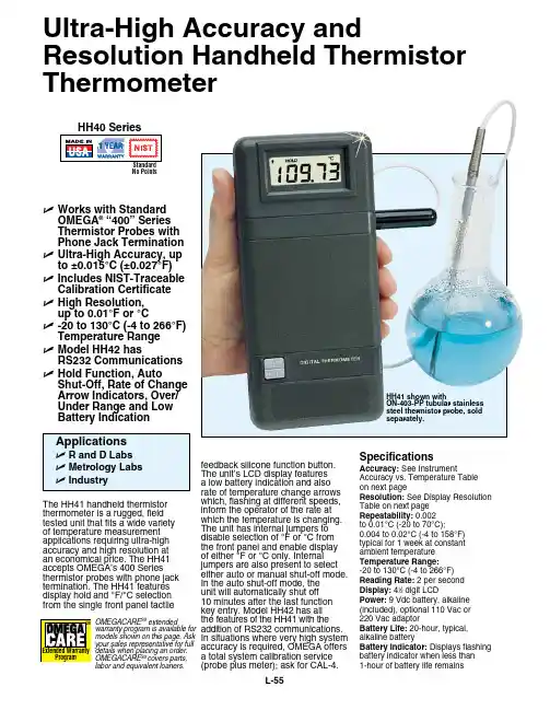
L-55feedback silicone function button. The unit’s LCD display features a low battery indication and also rate of temperature change arrows which, flashing at different speeds, inform the operator of the rate at which the temperature is changing. The unit has internal jumpers to disable selection of °F or °C from the front panel and enable display of either °F or °C only. Internal jumpers are also present to select either auto or manual shut-off mode. In the auto shut-off mode, the unit will automatically shut off 10 minutes after the last function key entry. Model HH42 has all the features of the HH41 with the addition of RS232 communications.In situations where very high system accuracy is required, OMEGA offers a total system calibration service (probe plus meter); ask for CAL-4.The HH41 handheld thermistor thermometer is a rugged, fieldtested unit that fits a wide variety of temperature measurement applications requiring ultra-high accuracy and high resolution at an economical price. The HH41 accepts OMEGA’s 400 Series thermistor probes with phone jack termination. The HH41 features display hold and °F/°C selection from the single front panel tactileU Works with Standard Omega ® “400” Series Thermistor Probes with Phone Jack Termination U Ultra-High accuracy, up to ±0.015°C (±0.027°F)U Includes NIST-Traceable Calibration Certificate U High Resolution, up to 0.01°F or °CU -20 to 130°C (-4 to 266°F) Temperature Range U model HH42 hasRS232 Communications U Hold Function, autoShut-Off, Rate of Change arrow Indicators, Over/Under Range and Low Battery IndicationHH41 shown withON-403-PP tubular stainless steel thermistor probe, sold separately.Ultra-High accuracy andResolution Handheld Thermistor ThermometerSpecificationsaccuracy: See InstrumentAccuracy vs. Temperature Table on next pageResolution: See Display Resolution Table on next page Repeatability: 0.002 to 0.01°C (-20 to 70°C);0.004 to 0.02°C (-4 to 158°F) typical for 1 week at constant ambient temperature Temperature Range: -20 to 130°C (-4 to 266°F)Reading Rate: 2 per second Display: 41⁄2 digit LCDPower: 9 Vdc battery, alkaline (included), optional 110 Vac or 220 Vac adaptorBattery Life: 20-hour, typical, alkaline batteryBattery Indicator: Displays flashing battery indicator when less than 1-hour of battery life remainsNo PointsOMEGACARE SM extendedwarranty program is available for models shown on this page. Ask your sales representative for fulldetails when placing an order.OMEGACARE SM covers parts,labor and equivalent loaners.a: ON-401-PP, general purpose probe B: ON-401-PP-V, flexible probe C: ON-403-PP, immersion probe D: ON-404-PP, glass probee: ON-405-PP, air temperature probeF: ON-408-PP, surface temperature probe g: ON-409-PP, surface temperature probe H: ON-410-PP, 1/8 NPT probe 4.5” longDisplay Resolution Temperature Unit Selection: °F/°C selectable from front panel function button, or internal jumpers Instrument accuracy* aBCDeFgH400 Series standard connectorOmega ® 400 Series thermistor probes (sold separately).A C o m p l e t eL i s t i n g o f T he r m i s t o r P r o b e s A v a i l a b l e O nl i n e。
压力传感器 TLEE-188-503-15691 ∙压力传感器– 400系列∙压力传感器– 501系列∙压力传感器– 503系列∙压力传感器– 505系列∙压力传感器– 506系列∙压力传感器– 511系列∙压力传感器– 515系列∙压力传感器– 516系列∙压力传感器– 520系列∙压力传感器– 528系列∙压力传感器– 680系列∙压力传感器– 691系列∙压力传感器– 522系列∙压力传感器– 527系列∙差压式压力传感器– 401系列∙差压式压力传感器– 402系列∙差压式压力传感器– 403系列∙差压式压力传感器– 652系列∙差压式压力传感器– 692系列∙差压式压力传感器– 698系列∙差压式压力传感器– 699系列∙差压式压力传感器∙电子式压力开关o电子式压力开关– 521系列o电子式压力开关– 529系列o电子式压力开关- 540系列o电子式压力开关- 548系列机械式压力开关∙机械式压力开关– 604系列∙机械式压力开关– 605系列∙机械式压力开关– 610系列∙机械式压力开关– 620系列∙机械式压力开关– 625系列∙机械式压力开关– 630系列压力液位计∙压力液位计– 681系列∙压力液位计– 712系列流量传感器∙流量传感器- 200系列∙流量传感器- 210系列∙流量传感器- 230系列∙流量传感器- 235系列∙流量传感器- 236系列∙流量传感器∙压力传感器芯片o压力传感器芯片– 509系列o压力传感器芯片– 513系列o压力传感器芯片– 513 大气压系列力传感器芯片– 410系列数字式显示仪∙数字式显示仪- 800系列∙数字式显示仪- 801系列附件∙散热器。

huba差压传感器说明书
瑞士富巴(瑞士HUBA)511系列压力变送器结构紧凑,在机械应力,EMC兼容性,操作可靠性方面具有极高规格,所以特别适合用于所有要求苛刻的工业应用.
此传感器使用了HUBA CONTROL近十年来发展的陶瓷技术,并使
用在数百万种应用之中,由于传感器结合采用了少有的集成电子设计,所以511系列在其温度范围下拥有很高的精度。
总之,511系列变送器具有体积小巧,优秀的性价比的特点。
可以测量气体或液体的压力
范围:相对压力-1~600Bar可选,绝对压力0-25Bar
过压:2或3倍的量程
精度:±0.3%
输出:0-5V/0-10V/4-20mA可选
瑞士HUBA 692系列压差变送器,并将其转换成标准的电流或电
压信号。
多种压力和电气连接以及外壳材料可供选择,以便适用不同的介质。
量程:0~2500Kpa
耐高温;抗温度波动;
精度:线性度、迟滞性、无机械老化现象;
重复性之和<±0.8%
无机械蠕变现象
模块系统,量体裁衣的设技术参数
系统压力:2500kPa(量程<600kPa);5000kPa(量程1000~2500)。
知识创造未来
huba传感器
huba传感器是德国HUBA CONTROL AG公司生产的压力传感器。
HUBA CONTROL AG是一家专业生产传感器的
公司,成立于1945年,总部位于德国。
HUBA传感器有多种型号和应用领域,包括汽车工业、医
疗设备、建筑自动化等。
它们可以测量液体和气体的压力,并将其转化为电信号输出。
HUBA传感器有很高的准确性和可靠性,可以广泛应用于
工业控制系统、仪器仪表和传感器网络等领域。
它们通常
使用标准的电气连接方式和接口,便于与其他设备进行集
成和通信。
总结来说,HUBA传感器是一种高质量的压力传感器,适
用于许多不同的应用场景。
1。

***********************Servicing North America:U.S.A. Omega Engineering, Inc.Headquarters: Toll-Free: 1-800-826-6342 (USA & Canada only)Customer Service: 1-800-622-2378 (USA & Canada only)Engineering Service: 1-800-872-9436 (USA & Canada only)Tel: (203) 359-1660 Fax: (203) 359-7700e-mail:**************For Other Locations Visit /worldwideThe information contained in this document is believed to be correct, but OMEGA accepts no liability for any errors it contains, and reserves the right to alter specifications without notice.CONTENTS1. Introduction (1)1.1 Specification (1)1.2 ModelNumber (2)2. Operation (2)2.1 Principle (3)2.2 Precautions (4)3. Installation (5)Piping (5)3.1 General3.2 Strainers/Filters (7)and Installation Kits (7)Straighteners3.3 Flow4. Maintenance (8)4.1 General (8)Procedures (8)4.2 Cleaning4.2.1 Chemical Cleaning (8)Cleaning (8)4.2.2 Steam4.3 PickupCoil Testing (10)Shooting (11)4.4 TroubleAppendix A: DrawingTypical Assembly Sanitary Flowmeter with Installation Kit (12)1.IntroductionThe following information is provided for the proper installation and maintenance of your instrument.1.1 SpecificationsLinearity: ± 0.5% of reading over linear flow rangeRepeatability:± 0.1% of readingFlow Range: 0.35 to 650 gpmTemperature Range: -450 °F to +450 °F w/ Standard MAG coilSignal Output: 10 mVrms or greater into 10K ohm load at minimum flow rate.Materials of Construction: 316/316L Dual Rated Stainless Steel Rotor 17.4 PH SSRetaining Ring 15.7 MO PH SSBearings: Hard Carbon Composite Surface Finish: 32 micro inch finish End Fitting: Tri-Grip® Sanitary Type-1-1.2 Model NumberLinear FlowRangeWater Model No.FittingsLPM GPMMaxPressureDrop(psid)Lengthmm(in)NominalK-factorPulses/GalWeightkg(lb)FTB-401A 11/2″ TRI 1.32 to13.20.35 to3.53.090.4(3.56)15,000 3 lbsFTB-402A 11/2″ TRI 2.84 to28.40.75 to7.55.090.4(3.56)8,900 3 lbsFTB-403A 11/2″ TRI 4.73 to361.25 to9.55.290.4(3.56)5,800 3 lbsFTB-404A 11/2″ TRI 6.62 to611.75 to163.090.4(3.56)5,200 3 lbsFTB-405A 11/2″ TRI 9.5 to1102.5 to295.082.5(3.25)2,200 3 lbsFTB-406A 11/2″ TRI 15 to2274 to 60 5.190.4(3.56)840 3 lbsFTB-407A 11/2″ TRI 23 to3526 to 93 4.3116.5(4.59)400 4 lbsFTB-408A 11/2″ TRI 30 to4928 to 130 3.0116.5(4.59)230 4 lbsFTB-409A 2″ TRI 57 to85215 to2253.3154(6.06)120 7 lbsFTB-410A 21/2″ TRI 95 to151425 to4004.0254(10)97 8 lbsFTB-411A 3″ TRI 151 to246040 to6504.0254(10)45 12 lbsNote: Operating pressure is limited by the TRI fitting.-2-2.Operation2.1 PrincipleThe turbine flow sensor consists of a rotor assembly which is supported on a shaft held in place by triple tube clusters and secured with locking nuts within the flowmeter housing.The rotor is free to spin on a self lubricated ceramic ball bearing. A magnetic type pickup coil is attached on the exterior of the flowmeter housing.A low mass rotor design allows for rapid dynamic response. The deflector cones eliminate downstream thrust on the rotor and allows for dynamic positioning of the rotor between deflector cones.The dynamic positioning of the low mass rotor provides wider rangeability and longer bearing life than that of conventional turbine flowmeters. Integral flow straightening tubes minimize the effects of upstream flow turbulence.As the liquid flows through the flowmeter the rotor spins at rate proportional to the volumetric liquid flowrate.Each rotor blade passing through the pickup coil generates an electrical pulse. The frequency of the pulses is proportional to flowrate. The summation of pulses represents total amount of liquid volume passed through the meter.The number of pulses generated per unit of volume is called the calibration factor or K-Factor. This calibration factor is used to calculate flowrate and total amount of flow.Material Selection and ConstructionThe housing is made of 316 stainless steel. The rotor is made of 17.4 pH stainless steel. Bearings are composite hard carbon, FDA approved.-3-Flowmeter CalibrationsThe standard calibration provided with an Omega turbine flowmeter consists of a 10-point water calibration that is traceable to NIST. Based on this water calibration, we derive an average k-factor for water for the flowmeter.The uncertainty of this calibration is typically 0.1%.The K-factor on turbine flowmeters used on liquid service is NOT density dependent.2.2 Precautions♦Do not drop the meter. Dropping the meter may result in damage to the meter housing and/or internals.♦Do not operate the meter at flowrates greater than the maximum flowrate marked on the meter. Operating at flowrates greater than the maximum flowrate may over-spin the meter. Over-spinning may result in damage to the meter.CAUTION:Avoid over-spinning the meter. Over-spinning the meter may result in damage to the meter internals and lead to meterfailure.-4-3.InstallationCAUTION:Turbine meter has to be installed with pickup coil pointing down (see Appendix A) to ensure proper cleanability.Inspect all packages for any indications of damage which may have occurred during shipment.Verify that all meter parts or auxiliary components have arrived with the shipment. Refer to the packing list/invoice for a detailed list of items included in the shipment.3.1 General PipingIt is required to install meter with a minimum straight run of pipe approximately 10 pipe diameters ahead of the inlet and 5 pipe diameters following the outlet to avoid any effect of fluid swirls.The meter housing is marked by a flow direction arrow and the inlet is marked ‘IN’ and the outlet is marked ‘OUT’. The meter must be installed in the piping in the correct orientation to ensure the most accurate operation.Install meter with adequate distance and isolation from electric motors, transformers, welding equipment and solenoids to avoid any electromagnetic interference from ambient electrical field.When it is expected that flow will be intermittent, the meter should not be mounted at a low point in the piping system. Solids which settle or congeal in the meter may affect meter performance.-5-Blocking and Bypass valves should be installed if it is necessary to do preventive maintenance on the flowmeter without shutting down the flow system. The Bypass valve can be opened before the Blocking valves are closed allowing the flow to continue while removing the turbine flowmeter for service.IMPORTANT: All flow lines should be purged prior to installing the meter. To prevent possible damage to the meter, install themeter ONLY in flow lines that are clean and free of debris. Upon initial start-up of the system a spool piece should be installed in place of the flowmeter so that purging of the system can be performed to remove all particle debris which could cause damage to the meter internals. In applications where meter flushing is required after meter service, care should be taken as to not over-spin the meter, as severe meter damage may occur.CAUTION:Avoid over-spinning the meter. Over-spinning the meter may result in damage to the meter internals and lead to meterfailure.-6--7-To maintain an accurate flow measurement it is necessary to maintain a downstream pressure sufficient to prevent flashing/cavitation. Flashing of the liquid will result in an indication of flow significantly higher than the actual flow. In order to eliminate this condition adequate downstream pressure must be maintained. The minimum required downstream pressure may be calculated using the following equation:Downstream pressure may be maintained by a downstream valve that provides the necessary downstream pressure to prevent flashing/cavitation in the metering run.3.2 Strainers/FiltersTurbine flowmeters are designed for use in a clean fluid service. However, the service fluid may carry some particulate material which would need to be removed before reaching the flowmeter. Under these conditions a strainer/filter may be required to reduce the potential hazard of fouling or damage that may be caused by foreign matter.METER SIZEMESH SIZEPARTICLE SIZE(Maximum)¼” to ½”100 .0055 5/8” to 1¼”70 .008 1½” to 3”40.015If a strainer/filter is required in the system, it should be located upstream of the flowmeter taking care that the proper minimum distance is kept between the strainer and flowmeter.3.3 Flow Straighteners and Installation KitsProper application of the Omega FTB-400A Series Flowmeter requires a minimum inlet straight pipe run of 10 pipe diameters and a minimum outlet straight pipe run of 5 pipe diameters.Installation kits for the Omega FTB-400A Series Flowmeter consist of two lengths of appropriate tubing cut to a length appropriate for the upstream and downstream straight pipe run with appropriate end fittings. Flow straightening sections may be provided within the installation kit. ()()essure xVapor essureDrop x essure Minimum Pr 25.1Pr 2Pr +=4.MaintenanceProcedures4.1 CleaningThe Omega FTB-400A Series flowmeters have been designed to allow for cleaning by commercially accepted practices. These include removing the flowmeter from the line for cleaning in an approved fluid, flushing the line with an approved cleaning solution, and steam cleaning. With all cleaning methods, care must be taken to not over-spin the meter, as severe meter damage may occur.CAUTION:Avoid over-spinning the meter. Over-spinning the meter may result in damage to the meter internals and lead to meterfailure.4.2.1 ChemicalCleaningThe flowmeters may be chemically cleaned using an approved cleaning solution by removing the meter from the service line and using a bath or by flushing the meter in place.The hard carbon composite bearing designs used have been tested and found to be compatible with the following CIP fluids manufactured by Klenzade; Mandate, AC-300, AC-101, Principle, and XY-12.Following the cleaning operation, the cleaning solution should be flushed from the meter and/or service line with potable water to remove the chemically active cleaning solution.Care should be taken to ensure that flowrates occurring during chemical cleaning do not exceed the flow capacity of the flowmeter.4.2.2Steam CleaningSteam cleaning is only recommended for meters with hard carbon composite bearings.The steam flow velocity during the cleaning should not exceed 1/3 of the maximum liquid flow capacity of the flowmeter.-8-Steam Cleaning Rates at Various Steam PressuresMeter Size 50 psigPPH175 psigPPH1100 psigPPH1125 psigPPH1VelocityFPS2RateGPM31/4 1.25 1.70 2.25 2.50 1.72 1.05 3/8 2.70 3.67 4.75 5.39 3.68 2.25 1/2 3.50 4.73 6.14 7.00 4.74 2.90 5/8 5.78 7.82 10.20 11.50 5.02 4.80 3/4 10.50 14.20 18.40 20.90 6.32 8.701 21.70 29.40 38.10 43.10 7.35 18.001¼ 33.70 45.70 59.30 67.10 7.32 28.00 1½ 47.00 63.60 82.50 93.50 7.08 39.002 81.30 110.10 142.80 162.00 6.89 67.502½ 144.60 196.00 254.00 288.00 7.84 120.003 235.00 318.00 412.60 467.00 8.85 195.00 NOTES1.PPH = Pounds Per Hour2.The velocity is expressed for a line size equal to the inlet bore of the flowmeter.3.The apparent GPM is provided since many applications have a flow rate indicatorwhich can be used to set a safe flow rate during the steam cleaning cycle.-9--10-4.3 Pickup Coil TestingTesting the MAG and MCP (RF) coils consists of measuring theresistance with an ohmmeter. Resistance measurements are to be madeonly when there is no flow through the meter.1. Measure the resistance between pin A and pin B. The resistanceshould be approximately as listed in the following table of somecommon coils.2. The resistance from any pin to the case should be greater than 1Mohm.COIL *DC RESISTANCE (Ohms) MC2PAHT15.0 ±10% MCP3A11.5 ±10% PC13-74G1800 ±10% PC13-74S1850 ±15% PC24-45G1350 ±10% PC24-45S1850 ±15% PC28-13G120 ±20% PC28-14G 180 ±20%If either resistance measurement fails, replace the pickup coil. Firmlyseat the new coil in the flowmeter and tighten the locking nut.*For specific coils not listed contact the HFC Customer Service Department for theapproximate resistance readings.4.4 TroubleShootingRefer to the following troubleshooting guide for assistance with possible meter malfunctions:TROUBLE CAUSE REMEDY Fluid will not flow ▪Meter clogged. Clean meter.through the meter ▪Line to meterblocked.Clean line to meter.Reduced flow through the meter ▪Meter partiallyclogged.Clean meter.▪Line to meterpartially blocked.Clean line to meter.Meter readings inaccurate ▪Fluid flowrate isnot within meterflow range.See “Specifications” formin and max flowrates.▪Meter drag due toimproperinstallationReplace internals.-11-DRAWINGTypical Assembly Sanitary Flowmeter with Installation Kit-12-WARRANTY/DISCLAIMEROMEGA ENGINEERING, INC. warrants this unit to be free of defects in materials and workmanship for a period of 13 months from date of purchase. OMEGA’s WARRANTY adds an additional one (1) month grace period to the normal one (1) year product warranty to cover handling and shipping time. T his ensures that OMEGA’s customers receive maximum coverage on each product.If the unit malfunctions, it must be returned to the factory for evaluation. OMEGA’s Customer Service Department will issue an Authorized Return (AR) number immediately upon phone or written request. Upon examination by OMEGA, if the unit is found to be defective, it will be repaired or replaced at no charge. OMEGA’s WARRANT Y does not apply to defects resulting from any action of the purchaser, including but not limited to mishandling, improper interfacing, operation outside of design limits, improper repair, or unauthorized modification. This WARRANTY is VOID if the unit shows evidence of having been tampered with or shows evidence of having been damaged as a result of excessive corrosion; or current, heat, moisture or vibration; improper specification; misapplication; misuse or other operating conditions outside of OMEGA’s control. Components in which wear is not warranted, include but are not limited to contact points, fuses, and triacs.OMEGA is pleased to offer suggestions on the use of its various products. However, OMEGA neither assumes responsibility for any omissions or errors nor assumes liability for any damages that result from the use of its products in accordance with information provided by OMEGA, either verbal or written. OMEGA warrants only that the parts manufactured by the company will be as specified and free of defects. OMEGA MAKES NO OTHER WARRANTIES OR REPRESENTATIONS OF ANY KIND W HATSOEVER, EXPRESSED OR IMPLIED, EXCEPT THAT OF TITLE, AND ALL IMPLIED W ARRANTIES INCLUDING ANY W ARRANTY OF MERCHANTABILITY AND FITNESS FOR A PARTICULAR PURPOSE ARE HEREBY DISCLAIMED. LIMITATION OF LIABILITY: The remedies of purchaser set forth herein are exclusive, and the total liability of OMEGA with respect to this order, whether based on contract, warranty, negligence, indemnification, strict liability or otherwise, shall not exceed the purchase price of the component upon which liability is based. In no event shall OMEGA be liable for consequential, incidental or special damages.CONDITIONS: Equipment sold by OMEGA is not intended to be used, nor shall it be used: (1) as a “Basic Component” under 10 CFR 21 (NRC), used in or with any nuclear installation or activity; or (2) in medical applications or used on humans. Should any Product(s) be used in or with any nuclear installation or activity, medical application, used on humans, or misused in any way, OMEGA assumes no responsibility as set forth in our basic WARRANTY / DISCLAIMER language, and, additionally, purchaser will indemnify OMEGA and hold OMEGA harmless from any liability or damage whatsoever arising out of the use of the Product(s) in such a manner.RETURN REQUESTS/INQUIRIESDirect all warranty and repair requests/inquiries to the OMEGA Customer Service Department. BEFORE RET URNING ANY PRODUCT (S) T O OMEGA, PURCHASER MUST OBT AIN AN AUT HORIZED RET URN (AR) NUMBER FROM OMEGA’S CUST OMER SERVICE DEPART MENT (IN ORDER T O AVOID PROCESSING DELAYS). T he assigned AR number should then be marked on the outside of the return package and on any correspondence.The purchaser is responsible for shipping charges, freight, insurance and proper packaging to prevent breakage in transit.OMEGA’s policy is to make running changes, not model changes, whenever an improvement is possible. This affords our customers the latest in technology and engineering.OMEGA is a registered trademark of OMEGA ENGINEERING, INC.© Copyright 2016 OMEGA ENGINEERING, INC. All rights reserved. This document may not be copied, photocopied, reproduced, translated, or reduced to any electronic medium or machine-readable form, in whole or in part, without the prior written consent of OMEGA ENGINEERING, INC.FOR WARRANTY RETURNS, please have the following information available BEFORE contacting OMEGA:1. Purchase Order number under which the product was PURCHASED,2. M odel and serial number of the product under warranty, and3. R epair instructions and/or specific problems relative to the product.FOR NON-WARRANTY REPAIRS, consult OMEGA for current repair charges. Have the following information available BEFORE contacting OMEGA:1. P urchase Order number to cover the COST of the repair,2. Model and serial number of the product, and 3. Repair instructions and/or specific problemsrelative to the product.Where Do I Find Everything I Need for Process Measurement and Control?OMEGA…Of Course!Shop online at SMTEMPERATUREM U Thermocouple, RTD & Thermistor Probes, Connectors, Panels & AssembliesM U Wire: Thermocouple, RTD & ThermistorM U Calibrators & Ice Point ReferencesM U Recorders, Controllers & Process MonitorsM U Infrared PyrometersPRESSURE, STRAIN AND FORCEM U Transducers & Strain GagesM U Load Cells & Pressure GagesM U Displacement TransducersM U Instrumentation & AccessoriesFLOW/LEVELM U Rotameters, Gas Mass Flowmeters & Flow ComputersM U Air Velocity IndicatorsM U Turbine/Paddlewheel SystemsM U Totalizers & Batch ControllerspH/CONDUCTIVITYM U pH Electrodes, Testers & AccessoriesM U Benchtop/Laboratory MetersM U Controllers, Calibrators, Simulators & PumpsM U Industrial pH & Conductivity EquipmentDATA ACQUISITIONM U Communications-Based Acquisition SystemsM U Data Logging SystemsM U Wireless Sensors, Transmitters, & ReceiversM U Signal ConditionersM U Data Acquisition SoftwareHEATERSM U Heating CableM U Cartridge & Strip HeatersM U Immersion & Band HeatersM U Flexible HeatersM U Laboratory HeatersENVIRONMENTALMONITORING AND CONTROLM U Metering & Control InstrumentationM U RefractometersM U Pumps & TubingM U Air, Soil & Water MonitorsM U Industrial Water & Wastewater TreatmentM U pH, Conductivity & Dissolved Oxygen InstrumentsM2124/0617。

ThermCal400Dry Block Temperature CalibratorINSTRUCTION MANUALPlease read all the information in this booklet before using the unit. August 2013The ThermCal400IntroductionThe ThermCal400 calibrator provides a safe, dry, constant temperature source for checking and calibrating a wide range of temperature sensors, systems, indicators and thermometers It is fast and economical and can be used either on a bench top or as a portable field unit. The weight of the unit is only 11 pounds/five kilograms. The unit covers the temperature range from 5°C above ambient up to 400°C using a machined aluminum block as the heat transfer medium. The temperature control circuit is built into the unit.Features include:• Maximum temperature of 400°C/752°F• An independent over-temperature cutout• Up to eight setpoints can be stored & recalledEven though the unit heats up rapidly, highly efficient insulation and an internal cooling fan ensures that the case remains cool enough to handle even at maximum operating temperatures. The ThermCal400 calibrator has been designed to comply with all relevant electromagnetic interference and electrical safety regulations.-1-SpecificationFigures quoted are at the base of the well at the time of calibration.Temperature range: 5°C/9°F above ambient to 400°C/752°FOver-temperature limit: 450°C/842°FDisplay resolution: 0.1°Accuracy: ±0.25°C (30 to 200°C)±0.4°C (200 to 400°C)Stability (after 20 minutes): ±0.020°C (50 to 200°C)±0.040°C (200 to 400°C)Well to well radial uniformity: 0.015°C at 200°C & 0.025°C at 400°CHeat up time 20° C to 300°C: 9 minutesCool down 300°C to 100°C: 18 minutesImmersion Depth: 4.5" (114.3mm)Fan Cooling: AutomaticWeight: 11 lbs (5 Kg)Dimensions* (H x W x D): 8.75 x 8 x 8 inches/222.25 x 203.2 x 203.2 mm*excluding the carrying strapElectrical supplyVoltage Cycles Power230V 50/60Hz 900W120V 50/60Hz 900WNote: The above specifications are quoted for an ambient temperature range of 10°C/50°F to 30°C/86°F.Outside this range, the quoted figures may deteriorate but the unit will still work safely.-2-Working environmentThe calibrator units are designed to work safely under the following conditions:Ambient temperature range: 5°C/9°F to 40°C/104°FHumidity: Up to 95% relative humidity, non-condensingWarningWarning: HIGH TEMPERATURES ARE DANGEROUSAviso: LAS TEMPERATURAS ELEVADAS SON PELIHIGH TEMPERATURES ARE DANGEROUS: They can cause serious burns to operators and ignite combustible material. Accurate Thermal Systems has taken great care in the design of these units to protect operators from hazards, but operators should pay attention to the following points:• USE CARE AND WEAR PROTECTIVE GLOVES TO PROTECT HANDS• DO NOT put hot objects on or near combustible objects• DO NOT operate the unit close to inflammable liquids or gases• DO NOT place any liquid directly in your unit• At all times USE COMMON SENSEOperator SafetyAll operators of Accurate Thermal Systems equipment must have available the relevant literature needed to ensure their safety. It is important that only suitably trained personnel operate this equipment in accordance with the instructions contained in this manual and with general safety standards and procedures. If the equipment is used in a manner not specified by Accurate Thermal Systems, the protection provided by the equipment to the operator may be impaired. All Accurate Thermal Systems units have been designed to conform to international safety requirements and are fitted with a self-resetting over-temperature cutout. If a safety problem is encountered, switch off at the power socket and remove the plug from the supply.-3-Installation1. All Accurate Thermal Systems units are supplied with a power cable.2. Before connecting the power supply, check the voltage against the rating plate. Connect the powercable to a suitable plug according to the table below. Note that the unit must be earth groundedto ensure proper electrical safety.Electrical connections:220V-240V 110V-120VLive Brown BlackNeutral Blue WhiteEarth ground Green/yellow GreenThe fused plug supplied with the power lead for use in the UK is fitted with the following value fuse to protect the cable: 230V UK 4 AMPThe fuse in the unit protects the unit and the operatorNote that units marked 230V on the rating plate work at 220V; units marked 120V work at 110V. Inboth cases, however, the heating rate will degrade by approximately 8%. The rating plate is on therear of the unit.3. Plug the power cable into the socket on the rear of the unit.4. Place the unit on a suitable bench or flat workspace, or in a fume cupboard if required, ensuring thatthe air inlet vents on the underside are free from obstruction.After use, when you have finished heating samples, remember that parts of the unit may be very hot.Take the precautions listed earlier.-4-OPERATIONPreparation1.The heater design, temperature sensor and control circuit give good temperature control anduniformity, but make sure that there is a close fit of the probes in the block to allow efficient heattransfer. Contact us about an insert that more closely fits your probe or device being calibrated.2. Plug the power cable into the socket in the back of the unit. Connect the power cable to theelectrical supply and switch the power on.Setting the operating temperature1.To set the operating temperature required, press and hold either the up or down arrow button toincrement to the value required. Alternatively you can press the («PF) key to move over toindividual digits to set higher values much quicker. After 2 seconds your value will be set & retained.2.When you have the correct set temperature displayed the unit will start to heat or cool to thatvalue.3. Once the process value/actual temperature reaches the set point, allow the block to fully stabilize forat least 15 minutes before performing a calibration.Entering up to 8 setpoints for fast recall1. To input up to 8 setpoints press the first button on the left and then the 2nd button from the leftuntil the top line displays SP-0. Here you can enter up to 8 values for fast future recall. Do notchange any of the settings or values after SP-7. When finished entering values press the button onthe left one time.You’ll need to note which value is in which location for future recall.2. To select one of the 8 setpoints for use from the main display press the 2nd button from the left sothe top line displays M-SP. Next use the up arrow key to select one of the 8 setpoint values. Pressthe 1st key on the left twice for the value to be accepted.-5-Factory default control parametersThe parameters used in the controller have been developed by Accurate Thermal Systems to give the best unit performance for most applications. If the need arises the “AT” autotune command can be run to further optimize results based on the thermal block load and ambient conditions. Contact us for further support and details.Switching the display from Degrees C to Degrees F and vice versaTo switch the display press and hold down the left key until the display indicates “CN-t”, next press the 2nd key from the left one time and the top line will show “d-U” which is display units. Switch to either C or F. Based on which setting you use the parameters below must be changed to those shown. They will display by pressing the 2nd key from the left after setting C or F. After all values have been changed hold down the left most key so the controller resets and accepts the new values.Parameter Degrees C Degrees FSL-H 410.0 770.0SL-L 0.0 0.0To correct the calibration offset – press button on left, then button 2ndfrom the left until the parameter CN5 is displayedCN5 If in C multiply valueby 1.8 to switch to F If in F divide value by 1.8 to switch to C-6-Operator maintenanceNOTE THAT THIS EQUIPMENT SHOULD ONLY BE DISMANTLED BY PROPERLY TRAINED PERSONNEL. REMOVING THE FRONT OR REAR PANELS EXPOSES POTENTIALLY LETHAL VOLTAGES. THERE ARE NO OPERATOR MAINTAINABLE PARTS WITHIN THE EQUIPMENT.In the unlikely event that you experience any problems with your unit which cannot easily be remedied, you should contact your supplier and return the unit if necessary. Please include any details of the fault observed and remember to return the unit in its original packing. Accurate Thermal Systems will accept no responsibility for any damage to units that are improperly packed for shipment. If in doubt, contact your supplier.1.Cleaning: Before cleaning your unit, ALWAYS disconnect it from the power supply and allow it tocool below 50° C. Your unit can be cleaned by wiping with a damp soapy cloth. Care should beexercised to prevent water from running inside the unit. Do not use abrasive cleaners.2.Fuses: Your unit is protected by fuse. They should only be changed by suitably qualifiedpersonnel. If the fuse blow persistently, a serious fault is indicated and you may need to return theunit to your supplier for repair.ADDITIONAL INFORMATIONThe controller is factory preset with all parameters and calibration data and therefore cannot becalibrated or serviced in the field. Please contact Accurate Thermal Systems for arrangements to haveyour unit calibrated or serviced.-7-Replacement PartsThe following parts may be obtained from Anville Instruments Ltd. if replacements or alternatives are required: Part Number Description4163 UK 240 volt power cable with 13amp UK plug (5 amp fuse)4164 Euro style 240 volt power cable with R/A Schuko plug4150 US style 120 volt power cable4159 Instruction manual4150 Unit carrying strap4153 Insert extractorATS3041 insert 1/8, 3/16, ¼, 5/16 & 3/8” ATS3047 Blank insertATS3043 Insert 5 x 1/4" ATS3048 insert 1 x 9/16" & 1 x 1/4"ATS3044 Insert 2 x 1/4" & 2 x 3/8" ATS3049 insert 1 x 5/8" & 1 x 1/4"ATS3045 Insert 2 x 1/4" & 2 x 1/2" ATS3050 insert 1 x 11/16" & 1 x 1/4" ATS3046 Insert 1 x 1/4" ATS3051 insert 1 x 3/4" & 1 x 1/4"ATS3052 Carrying caseSpare PartsPart Number Description4146 225 watt, 120 volt heater4160 Temperature controller4147 PRT4145 Solid state relay4165 4 amp fuse (240 volt units)4157 8 amp fuse (120 volt units)-8-Contact InformationAccurate Thermal Systems LLC61 Mohr RoadBurlington, NJ 08016Ph: 609-326-3190Email:***********************Website: GUARANTEEThe unit is guaranteed against any defects in material or workmanship for the period of 3 years. This period is from the date of purchase, and within this period, all defective parts will be replaced free of charge provided that the defect is not the result of misuse, accident or negligence. Servicing under this guarantee should be obtained from the supplier. Not withstanding the description and specification(s) of the units contained in the Operator’s Manual, Accurate Thermal Systems hereby reserves the right to make such changes as it sees fit to the units or to any component of the units. This manual has been prepared solely for the convenience of Accurate Thermal Systems customers and nothing in this Instruction Book shall be taken as a warranty, condition or representation concerning the description, merchantability, fitness for purpose or otherwise of the units or components.-9-。
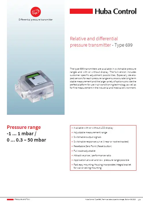
1/5Huba Control Type 699 | Technical data subject to change | Edition 09/2020Pressure and fl owThe type 699 transmitters are available in switchable pressure ranges and with or without display. The full-version includes customer specific adjustment possibilities. Especially develo-ped sensors for each pressure range ensure accurate long term stable measurement and the large variety of options provide the perfect platform for use in air conditioning technology as well as for fine measurement in the industrial and medical environment.Relative and di ff erentialpressure transmitter -Type 699Differential pressure transmitter+ Available with or without LCD display + Adjustable measurement range + Switchable output signals+ Switchable response curve (linear or root-extracted)+ Resettable Zero Point (Reset button) + Full scale adjustable+ Attractive price / performance ratio+ Application at over and low pressure range possible + Fast, easy mounting. Housing incorporates integral bracket for wall or ceiling mountingPressure range -1 ... 1 mbar / 0 ... 0.3 – 50 mbar2/5Huba Control Type 699 | Technical data subject to change | Edition 09/2020Pressure and fl owPressure rangeRelative and differential-1 ... 1 mbar / 0 ... 0.3 – 50 mbar Operating conditions MediumAir and neutral gases TemperatureMedium / ambient 0 ... +70 ºCStorage-10 ... +70 ºCNo cond e nsationTolerable overload on one sideApplication at over pressure range< 3 mbar P1 = 50 mbar P2 = 4 mbar> 3 mbar P1 = 100 mbar P2 = 4 mbar Application at under pressure range< 3 mbar P1 = -4 mbar P2 = -50 mbar> 3 mbarP1 = -4 mbar P2 = -100 mbarRupture pressureambient temperature 2 x overload70 ºC1.5 x overloadMaterials in contact with mediumS e nsorC e ramic Al 2O 3 (96%)Diaphragm Silicon eHousingPolycarbonat PCElectrical overviewOutput 1) Pow e r supply 1) Load Curr e nt consumption 2)2 wire 4 ... 20 mA 8.0 ... 33 VDC < supply voltage - 8 V[Ohm] < 20 mA 3 wire 0 ... 10 V 13.5 ... 33 VDC / 24 VAC ±15% > 10 kOhm < 10 mA 0 ... 20 mA 13.5 ... 33 VDC / 24 VAC ±15% < 500 Ohm < 30 mA 4 ... 20 mA 13.5 ... 33 VDC / 24 VAC ±15% < 500 Ohm < 30 mA 0 ... 5 V 3) 6.5 ... 33 VDC / 24 VAC ±15% > 10 kOhm < 10 mA Filter Response time switchable by off / 0.2s / 1s / 5s / 20s Polarity reversal protection Short circuit proof and protected against polarity reversal. Each connection is protected against crossover up to max. supply voltage.Dynamic response Response time < 20 ms Load cycle< 10 HzProtection standard Without coverIP 00With coverIP 54IP 65DisplayLCD DisplayDouble spaced per 8 digit alphanumericAt additional backlight LCD-Display 30 mA current consumption Module MODBUSRTU RS-485Ranges of adjustmentThe zero piont is adjustable by reset button.The Full scale is adjustable by DIP-Switch and additional by the turbopoti.AdjustabilityOptional version with self configurable parameters (see order code selection table)Electrical connectionScrew terminals for wire and stranded conductors up to 1.5 mm 2Cable gland with built-in strain relief PG11Pressure connection Connection pipeØ 6.2 mmMounting instructions Installation arrangement Recommendation: Vertical, (Factory calibration) with pressure connections downwards MountingMounting bracket (integrated in case)Tests / Admissions ULElectromagnetic compatibilityCE-conformity acc. EN 61326-2-3 WeightWithout display ~ 90 g With display~ 100 gPackagingSingle packaging in cardboard Multiple packaging20 / 40 / 1200.02 A3/5Huba Control Type 699 | Technical data subject to change | Edition 09/2020Pressure and fl owOut100%a)Pressurec)Out b)Test conditions:25 ºC, 45% rF, Power supply 24 VDC TC z.p. / TC z.p. 0 … 70 ºC- no additional root-extracted errors - For changing diaphragm position, compensable with zero point reset ParameterUnit±0.5 mbar0 ... 1 mbar0 ... 3 mbar0 ... 5 mbar0 ... 10 - 50 mbarTolerance zero point max.% fs ±1.0±1.0±0.7±0.7±0.7Tolerance zero full scalemax.% fs ±1.0±1.0±0.7±0.7±0.7Resolution % fs0.2 0.2 0.1 0.1 0.1Total of linearity, hysteresis and repeatability max.% fs ±1.0±1.0±1.0±1.0±0.6Long therm stability acc. to DIN EN 60770% fs ±1.0±1.0±1.0±1.0±1.0TC zero point 1) typ.% fs/10K ±0.2±0.2±0.2±0.1±0.1TC zero point 1) max.% fs/10K ±1.0±1.0±0.5±0.4±0.4TC sensitivity 1) typ.% fs/10K ±0.3±0.3±0.2±0.1±0.1TC sensitivity 1)max.% fs/10K±0.6±0.6±0.5±0.5±0.24/5Huba Control Type 699 | Technical data subject to change | Edition 09/2020Pressure and flow9297EN 60 715-TH 35-7.54512835.2611.6Fig. 3Fig. 1Fig. 2Universal2 and3 wire3 wire2 wire Connection kit for vent duct (metal), 90º angled including tube 2 m long (Fig. 1) 104312Connection kit for vent duct (plastic), straight including tube 2 m long (Fig. 2) 100064DIN-rail mounting adaptor (Fig. 3) 112854Module MODBUS 117305Calibration certificate104551V rsion Variabl e param e t e rs Dual DIP-Switch Pressure ranges in grades Tenfold DIP-Switch Pressure ranges in grades; stepless adjustable with Turbo-Poti / output signals / fi lter (o ff / on) / response curve (linear / root extracted)Te nfold DIP-Switch with Display Pre ssure range s in grade s; ste ple ss adjustable with Turbo-Poti / pre ssure units / pre ssure range characte r / output signals; additional 0 ... 5 V / fi lter (o ff/ 0.2s / 1s / 5s / 20s) / response curve (linear / root extracted) / backlight (o ff / 5min / on)Huba Control AG Headquarters Schweiz Industriestrasse 17CH-5436 Würenlos Telefon +41 56 436 82 00Fax+41 56 436 82 82***********************Huba Control AGBranch O ff ice United KingdomUnit 13 Berkshire House, County Park Business Centre, Shrivenham Road Swindon Wiltshire SN1 2NR Phone +44 1993 77 66 67Fax+44 1993 77 66 71***********************Huba Control SA Succursale France Rue LavoisierTechnopôle Forbach-Sud F-57602 Forbach Cedex Téléphone +33 3 87 84 73 00Télécopieur +33 3 87 84 73 01***********************Huba Control AG Niederlassung Deutschland Schlattgrabenstrasse 24D-72141 Walddorfhäslach Telefon +49 7127 2393 00Fax+49 7127 2393 20***********************Huba Control USA, Inc.O ff ice United States of America 303 Wyman Street Suite #300Waltham MA 02451Tel: +1 866-6HUBACO (+1 866-648-2226)************************Huba Control AG Vestiging Nederland Hamseweg 20A NL-3828 AD-Hoogland Telefoon +31 33 433 03 66Telefax+31 33 433 03 77***********************。

2763 / 2767 / 2769全自动互感器试验装置特点⏹ 单台仪器测量电流及电压互感器。
⏹ 全自动测量、数字显示电流/电压比误差、相移、试验电流及电压。
⏹ 可测量互感器的一次侧和二次侧的电流和电压。
⏹ 测试变压器和标准变压器的变比可以不同。
⏹高性价比:单台标准变压器即可测试不同的变压器;不同的标准变压器和试验变压器变比无需外部分压器即可相互匹配。
⏹ 可输入交互参数以简化操作。
⏹ 测量进行期间,微处理器监控所有输入和控制。
⏹ 2 x 16字符点阵,纯语言显示错误信息。
⏹ 测量耗时短。
⏹ 动态平均。
⏹ 精度高。
⏹ 固有负载低。
⏹ 可连接至外部打印机(RS 232C 接口) ⏹ 前板设有压电晶体制键盘。
⏹产品规格遵从IEC 60044-1, IEC 60044-2; IEC 60044-3; IEC 60044-7,ANSI/IEEE C57.13-1978 和 VDE 0414, part 2标准。
⏹ 含RS 232C接口用于连接计算机。
可选配件⏹ 遥控测量过程用- IEEE 488 接口 ⏹更多可选配件参见采购信息综述TETTEX 仪器公司出产的2767型电流/电压互感器自动测试装置是一款高效、精确的互感器测量仪,专为实验室、工业生产、质量管理及官方计量站应用而设计。
随着现今质量管理标准的日益严格,测量设备的操作舒适度和可靠性越发受到关注。
该款测试仪基于最新技术开发,开创了质量、可靠性、可操作性和可维护性上的新标准,在电流/电压误差、相位差和激励电流/激励电压的测量范围上,该仪器完全符合国际标准。
该仪器经过德国物理技术研究院(PTB )测试,校正核准,完全符合PTB 仪表变压器测试标准。
全套测试系统同时,TETTEX 仪器公司也设计并销售计算机控制电流和电压互感器测量设备,以满足客户的特定需求,它们包括: ⏹ 2767型组合测试装置,用于电流和电压比互感器测试。
⏹ 4760系列标准电流互感器(电流比较器)。
空气压缩机零配件介绍GENTLY螺杆主机—所有产品都采用进口主机,其主机上都采用瑞典质量最高SKF的面对面安装滚锥轴承,其轴承以线接触方式承受力载负荷。
这样就大大的延长了轴承的使用寿命。
GENTLY主机上装有一个轴承油槽,在主机停机时,可以大量储存冷却剂,这样可以更好的降低压缩机重新起动工作时内腔的温度与更好地润滑,从而延长了主机的使用寿命。
螺杆转子采用最新设计的5:6非对称齿形,由线密封到带密封的优化型线,利于形成油膜,极大地减小内泄漏,因此可以24小时连续高效的运行。
微电脑智能控制系统(节能控制器)GENTLY所有产品均采用独自开发、设计的PLC智能微电脑控制系统。
整个系统都由一个中央处理器完成系统管理工作,各个零件都由各种传感器来完成信息输送的工作,并能自动监控控制、多机连控(由程序自动来控制所联接的压缩机系统)、或通过485口接到用户电脑来实现人机对话,系统语言并能中英文互换提高语言的可行性,系统还有一个储蓄器来完成压缩机系统的各种信息的储蓄,方便压缩机系统的日常维护。
从而系统的目的就是为每一个客户易于操作、维护和更节约费用。
大大减少操作人员的工作量与一些客观因素所引起的不必要故障而造成的费用。
1、压缩机的自动保护功能。
A、电机过载保护——自动停机B、排气温度过高保护——自动停机C、超压力压缩保护——自动停机D、电源相路出错保护——自动停机E、油细分离器堵塞——警告F、.机油过滤器堵塞——警告G、空气滤清器堵塞——警告H、润滑油量提示A、排气压力显示B、润滑油油压显示C、排气温度显示D、运行累计时间显示E、电机过载显示F、压缩机运行显示G、压缩机停机显示A、具有警示复位、清除旧信息功能B、具有对故障警示提供诊断相应资料功能C、具有故障汇记功能D、具有远程通讯功能E、具有24台机组联机功能✧比例调节进气阀1)特殊设计的侍服气缸,调节范围0—100%;2)具有止回功能,无须加装油路止回阀和断油阀;3)配有机械式放空阀;✧反比例容量调节阀1)较一般膜片式容调阀,寿命更长,无易损件;2)调节范围宽;3)调节压力动作稳定;✧压力维持阀1)开启压力准确可靠;2)带止回功能;3)压力损失小;4)阀芯采用非金属,不会有生锈所引起的动作失灵;✧温控阀1)热敏感元件动作稳定,有效避免油在低温和高温下工作;2)油温有效控制在70—85℃;3)阀芯动作稳定,无卡死误动作故障;✧油过滤器1)过滤精度10微米;2)压差小;3)带压差报警发讯器;✧油细分离器1)带预分离的三层分离;2)压差小初始压差0.2bar;3)分离效果好,残油量为1—3mg/m3;4)抗压强度高,能承受5bar压差✧双螺杆压缩机通用油1)有效减少主机泄露;2)有效提高主机寿命;3)不结焦;✧西门子接触器1)所有接触器加装阻容吸收器;2)欧姆龙逆项保护器;3)BURKERT电磁阀;3 / 18GENTLY压缩机技术优势GENTL Y压缩机在研究、制造过程中,主要地注重了减少不必要的维护费用和时间。
1)室外温湿度传感器现场使用的室外温湿度传感器主要有两个型号QFA3160 电源:24VDC;输出:0-10VQFA3171电源:24VDC;输出:4-20mA按上图片可以修改传感器的信号类型和量程范围,信号类型出场都是调试好的,基本不用改。
量程范围根据当地气候,一般情况用R3档。
上图为传感器接线图(需要注意QFA3171温度和湿度需要单独供电)。
调试的时候需要检查1.传感器供电(一般为24VDC,特殊类型需查看说明书)。
2.传感器和模块上的接线(电压和电流型在AI模块上的接线不同)。
3.传感器量程;信号类型是否和硬件组态中一致。
4.改完量程一定要盖上传感器的盖子才能正确度数5.程序中的FC105的上下限应与计算值对应。
2)水管温度传感器现场使用的室外温湿度传感器主要有两个型号PT100和LG-Ni1000;PT100为温度0度时电阻为100欧姆的铂电阻,LG-Ni1000是指温度0度是电阻为1000欧姆的镍电阻。
接线方式分为2线制和3线制。
3线制的接法可以消除线组对传感器测量数值的影响传感器端只有两个段子,3线制接线方法为将其中两个线接到传感器一个段子上,模块端分别接在S-和M-上,剩余的一根线接到M+上;2线制的接法为将两根线分别接到传感器两个段子上,模块端分别接在M+和M-,同时将模块端S-和M-短接。
硬件组态的时候,如果选择的是PT100Sta.,那么程序中除以10,如果选择的是PT100Cl.,就要除100。
3)流量传感器流量传感器型号:DWM2000电源:24VDC输出:4-20mA接线方法和设置如下图:拨码的计算调试的时候需要检查1.传感器供电(一般为24VDC,特殊类型需查看说明书)。
2.传感器和模块上的接线。
3.传感器量程;信号类型是否和硬件组态中一致。
4.必须在不开水泵,同时保证管道中液体静止时才能调零。
5.程序中的FC105的上下限应与计算值对应。
4)西门子压力传感器型号:QBE2002电源:24VDC输出:0-10V接线方法:现场很多西门子传感器线的颜色为棕、蓝、白与接线图上线色不同,但是还是按照棕—供电、白—GND、蓝—输出信号的接法。
0970 0007 VA 400 Chinese, V1.03, 02.04.08VA 400 热式质量流量传感器产品特点1希尔思的流量传感器VA 400是基于热式质量流量原理设计的。
其测量标准容积流量,量程大,并且测量值不受压力和温度影响。
该传感器可通过一个1/2英寸球阀安装到管道内。
这使得安装过程可以在不关闭压缩空气系统的情况下带压完成。
该传感器有两个量程可供选择,并且可带显示或不带显示。
带显示的型号会显示实际容积流量和总消耗量。
管道直径和消耗量基数可以通过按键来设置。
包括气体种类、流量单位和参考标准在内的各种设置可在工厂或通过我们的服务套装来设定。
服务套装内包含一个电脑软件以及一个能将传感器连接到电脑的USB端口的服务套装转换器。
每一个传感器都提供一个与流量对应的模拟输出(4…20mA)和一个与消耗量基数对应的电气隔离脉冲输出。
· 插入式设计,可带压安装· 基于热式质量流量原理,测量值不受压力和温度影响· IP65外壳,即使在恶劣工业环境中也能提供良好保护· 响应迅速· 精度高,量程大· 管道直径:1/4” 至 12” (其他管径可根据客户要求订做)0970 0007 VA 400 Chinese, V1.03, 02.04.082用户必须在启动仪器之前完整地阅读操作指南,并加以认真遵守。
对于因不遵守本手册规定而造成的任何损坏,制造商概不负责。
如果用户违反本手册所描述或规定的程序,擅自改动仪器,则仪器的保修将失效,并且制造商对此不须承担任何责任。
仪器只能按所说明的专门用途加以使用。
对于仪器是否适用于任何其他用途,希尔思仪表不作任何的保证,并且不对于本手册中可能包含的错误负责。
对于由本仪器的交付、性能及使用导致的损坏,希尔思仪表不承担责任。
希尔思的 VA 400 型产品可在压缩空气管道、空气输送管或通道中作固定式或移动式使用。
它可用于测量和控制压缩空气和其它气体的流量与消耗量。
WT-400M 系列智能四回路显示控制变送仪表使用说明书电子四十六所天津索思仪表测控系统技术有限公司联系人:周金宝 邹菁 王树洁 地址:天津市南开区科研西路20号 邮编:300192 电话:022-******** 87893040 87899183 87890392 87899181(传真) 公司网址: E-mail :sales@二、主要技术指标一、基本功能及特点● 精度: 0.5级适用于温度、压力、流量、液位、重量等工业过程参数的测量与显示,并且可以选择对过程参数进行报警或位式控制,还可以选择将过程参数变送输出给后级仪表、记录仪、计算机或采集系统等。
● 显示:4路4位数字显示 (0.56”LED 红色)● 显示分辨率:1● 输入信号: Pt100、Cu50、BA1、热电偶(N、K、E、J、T、S、R、B )、 ● 四排显示可以同时显示四路测量值 ● 高性能开关电源,交、直流通用输入 DC 4~20mA、 0~10mA、 1~5V、 0~5V● 输出信号: 继电器触点输出220V/1A(阻性负载,内部电火花消除电路)DC24V 供电 <30mA● 输入分度、量程可以通过面板按键设定● 最多可以带4个报警,报警控制方式、报警限、回差值可以通过面板按键设定 ● 工作条件: 环境温度 0~50℃ 相对湿度 ≤85% RH 避免强腐蚀性气体仪表电源 AC 60~260V 或 DC 24~350V 全范围、无极性● 最多可以带2路隔离变送输出,输出方式、变送量程可以通过面板按键设定 ● 可以提供馈电输出● 仪表重量: <470g● 可以带RS485/RS232/RS422隔离通讯接口,MODBUS 协议三、仪表使用方法 3、后端子接线说明:1、仪表外形及开孔尺寸:WT-400M 系列横式后端子图(竖式将上图逆时针旋转90度)160×80×140 mm 横式 80×160×140 mm 竖式开孔152+0.5×76+0.5 mm 开孔76+0.5×152+0.5 mm2、显示面板及按键使用说明:名称 内容 Ⅰ号显示屏 正常状态下,显示第一回路测量值 参数设定状态下,显示参数设定值 Ⅱ号显示屏 正常状态下,显示第二回路测量值 参数设定状态下,显示参数名提示符 Ⅲ号显示屏 正常状态下,显示第三回路测量值 显示屏Ⅳ号显示屏正常状态下,显示第四回路测量值 S参数设定入口按键(长按该键5秒钟以上,进入参数设置状态)参数设定确认按键(修改参数后,按一下保存参数并进入下一参数)♦ 参数设定时,用于移动光标(每按一下,参数闪烁位循环左移)▲ 参数设定时,用于增加数值(每按一下,正闪烁位数字加一)按键Q 参数设定时,参数修改状态下,取消修改当前参数值参数设定时,参数无改动状态下,退出设置AL1 第一回路有超限报警时灯亮AL2 第二回路有超限报警时灯亮AL3 第三回路有超限报警时灯亮指示灯AL4第四回路有超限报警时灯亮★ 以上接线图仅供参考。
压力传感器
OEM 压力传感器– 400系列
0 ... 10 - 100 mbar
400系列压力传感器采用瑞士富巴自己开发的悬臂樑陶瓷芯片,其输出的电压信号经过温度补偿。
已被放大和线性处理的电压输出信号可直接直接适用于电气控制系统。
400系列压力传感器非常适合白色家电产品(如洗衣机,洗碗机等)的容器液位的连续测量。
有最小订货量要求
OEM 压力传感器– 501系列
-1 ... 0 - 60 bar
501系列压力传感器采用瑞士富巴自己开发的陶瓷芯片,其电流输出信号经过校准和放大。
多种压力和电气接头可供选择。
有最小订货量要求
OEM 压力传感器– 503系列
0 ... 2.5 - 25 bar
503系列压力传感器采用瑞士富巴自己开发的陶瓷芯片,其电压输出信号经过校准和放大的。
专为大批量OEM生产而设计。
有最小订货量要求
OEM 压力传感器– 505系列
0 ... 4 bar
505系列压力传感器特别适用于加热和工业循环流体中水压比的测量。
陶瓷芯片由瑞士富巴自己开发的。
输出的电压信号经过校准和放大。
专为大批量OEM生产而设计。
在壁挂炉里得到广泛的应用。
有最小订货量要求
OEM 压力传感器– 506系列
-1 ... 7 - 60 bar
506系列压力传感器采用瑞士富巴自己开发的陶瓷芯片,输出信号经过校准和放大,适用于标准化电流输出。
专为工业制冷系统而开发。
有最小订货量要求
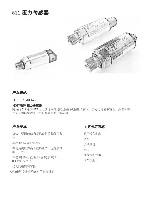
OEM 压力传感器– 511系列
-1 ... 0 - 600 bar
OEM 压力传感器– 515系列
-1 ... 0 - 600 bar
515系列压力传感器结构紧凑,在机械应力、EMC兼容性、操作可靠性方面具有极高规格。
OEM 压力传感器– 516系列
–1 … 0 – 16 bar
516系列压力传感器应用瑞士富巴开发的陶瓷技术,最近十年来使用在数百万种应用之中。
此传感器结合采用独特的集成电路设计,在其温度范围下拥有极高的精度。
516系列压力传感器采用放大辐射输出信号技术,可以直接装配使用,无需用户调节温度或压力。
固定订货量
压力传感器– 520系列
-1 ... 9 bar / 0 ... 2.5 – 600 bar
520系列压力传感器应用了瑞士富巴开发的厚膜技术。
压力传感器芯片被焊接到压力接头上。
因而适用于制冷业包括氨水在内的所有气体和液体制冷剂。
520系列压力传感器结合采用独特的集成电路设计,在其温度范围下具有优越的电磁兼容性和极高的精度。
广泛应用于制冷,液压和气动控制等各种工业自动化技术中。
压力传感器– 528系列
–1 ... 0 – 60 bar
结构紧凑的528系列压力传感器基于瑞士富巴开发的陶瓷传感器芯片。
经过20多年的持续开发和使用,其性能和稳定性得到充分证明。
528系列的传感器使用适用于各种领域的自动控制。
压力传感器– 680系列
0 ... 0.1 - 1000 bar
680系列压力传感器采用压电电阻测量芯片,产生经过补偿校准和放大的传感器信号,适用于标准化电压或电流输出。
多种压力和电气接头可供选择。
此传感器采用不锈钢材质。
先进的模块结构系统,独特的工业设计,可满足特殊工业应用要求。
压力传感器– 691系列
-1 ... 0 - 600 bar
691系列压力传感器采用独特的陶瓷技术,最近十年来使用在数百万种应用之中。
此传感器产生经过校准和放大的传感器信号,适用于标准化电压或电流输出。
多种压力和电气接头可供选择。
压力传感器– 522系列
0 ... 2.5 – 600 bar
522系列船舶用压力传感器应用了瑞士富巴开发的厚膜不锈钢压力芯片。
压力传感器芯片被焊接到压力接头上,广泛应用于各种高要求的工业自动化技术中。
522系列船舶用压力传感器已经通过美国、法国、挪威、德国劳埃德和英国劳埃德船级社认证。
压力传感器– 527系列
0 ... 1 – 60 bar
结构紧凑的527系列压力传感器基于瑞士富巴开发的陶瓷传感器芯片。
经过20多年的持续开发和使用,其性能和稳定性得到充分证明。
527系列的传感器使用适用于各种领域的自动控制,尤其是船舶制造业,已经通过美国、法国、挪威、德国劳埃德和英国劳埃德船级社认证。