最小二乘法电机故障诊断
- 格式:pdf
- 大小:1.03 MB
- 文档页数:5


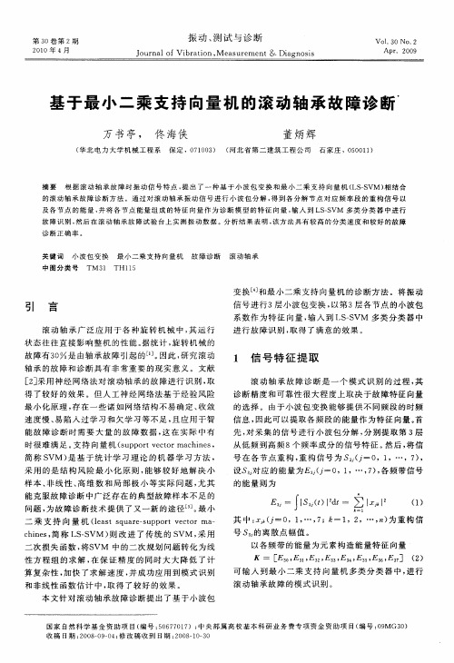
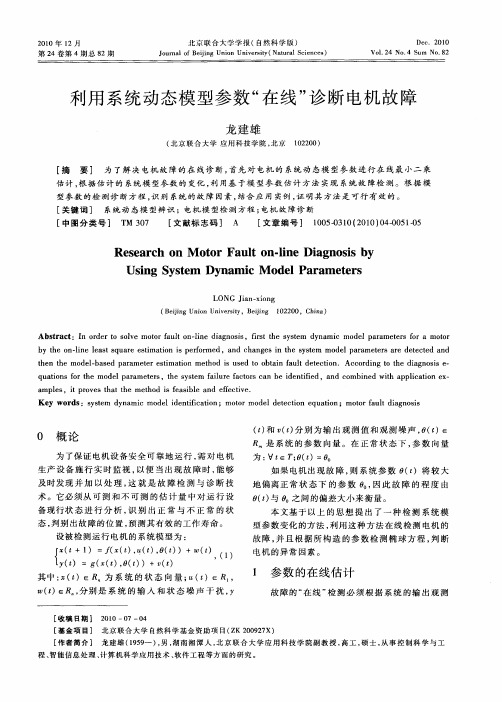
基于参数辨识法的异步电动机故障诊断许允之;王臻;刘艳;张倩【摘要】参数辨识法是异步电动机在线故障诊断的有效方法.根据定子电压、电流数据,采用递推最小二乘算法,计算电动机参数,在线辨识电动机故障,并讨论渐消记忆递推最小二乘法中遗忘因子对参数辨识的影响.鉴于模型的复杂性,用灰色系统观点线性化异步电动机模型,使参数快速收敛,但参数缺乏明确的物理含义.从电动机内部电磁关系入手,建立鼠笼异步电动机旋转坐标系电磁模型,消除磁链变量,避免磁链观测,达到故障诊断的目的.【期刊名称】《煤矿机电》【年(卷),期】2014(000)006【总页数】5页(P40-44)【关键词】参数辨识;递推最小二乘法;灰色系统;坐标变换【作者】许允之;王臻;刘艳;张倩【作者单位】中国矿业大学信息与电气工程学院,江苏徐州221116;华中科技大学电气与电子工程学院,湖北武汉430074;中国矿业大学信息与电气工程学院,江苏徐州221116;中国矿业大学信息与电气工程学院,江苏徐州221116【正文语种】中文【中图分类】TM307+.10 引言鼠笼型异步电动机最常见的故障为转子断条故障。
如果不能及时发现,转子断条故障将使电动机运行状态不断恶化。
基于故障频率分量fb=(1±2ks)f1进行频谱分析的方法[1-3]和基于神经网络[4]和遗传算法[5]进行参数识别的多种方法,大多很难消除参数与磁链之间的耦合,增加了实际检测诊断的难度。
本文用最小二乘算法快速有效地求解异步电动机状态间接参数[6,7],通过与正常状态参数作比较,在线诊断电动机转子断条故障,有效地避免了磁链观测,实际应用中证明此方法可靠有效。
2 基于参数识别的故障诊断方法2.1 辨识法原理通过识别电机参数可以诊断鼠笼型电动机断条故障[8]。
假设系统为:式中,y为输出变量;u为输入变量;e为系统噪声;θ为系统参数。
e一般是均值为零的高斯白噪声。
忽略其影响,则式(1)可以写成矩阵形式:式中, Y=[y(1)y(2) … y(m)];y(k),u(k)分别为tk时刻的输出和输入。


电机动态参数的鲁棒最小二乘辨识方法研究电机动态参数的鲁棒最小二乘辨识方法是一种常用的电机参数辨识方法,它可以通过对电机的输入输出数据进行处理,得到电机的动态参数,从而实现对电机的控制和优化。
本文将介绍电机动态参数的鲁棒最小二乘辨识方法的研究。
一、电机动态参数的鲁棒最小二乘辨识方法的基本原理电机动态参数的鲁棒最小二乘辨识方法是一种基于最小二乘法的电机参数辨识方法。
它的基本原理是利用电机的输入输出数据,通过最小二乘法对电机的动态参数进行辨识。
具体来说,它可以通过以下步骤实现:1. 收集电机的输入输出数据,包括电机的电流、电压、速度、位置等参数。
2. 建立电机的动态模型,包括电机的电路模型和机械模型。
3. 利用最小二乘法对电机的动态参数进行辨识,包括电机的电阻、电感、转动惯量、摩擦系数等参数。
4. 对辨识结果进行鲁棒性分析,评估辨识结果的可靠性和精度。
二、电机动态参数的鲁棒最小二乘辨识方法的研究进展电机动态参数的鲁棒最小二乘辨识方法是一种经典的电机参数辨识方法,已经得到了广泛的应用和研究。
近年来,随着电机控制技术的不断发展和电机应用领域的不断拓展,电机动态参数的鲁棒最小二乘辨识方法也得到了进一步的研究和改进。
1. 基于神经网络的电机参数辨识方法神经网络是一种强大的模式识别和数据处理工具,已经被广泛应用于电机参数辨识领域。
基于神经网络的电机参数辨识方法可以通过对电机的输入输出数据进行训练,得到电机的动态参数,具有较高的精度和鲁棒性。
2. 基于模糊逻辑的电机参数辨识方法模糊逻辑是一种基于模糊集合理论的推理方法,可以处理不确定性和模糊性问题。
基于模糊逻辑的电机参数辨识方法可以通过对电机的输入输出数据进行模糊化处理,得到电机的动态参数,具有较高的鲁棒性和可靠性。
3. 基于深度学习的电机参数辨识方法深度学习是一种基于神经网络的机器学习方法,可以处理大规模、高维度的数据。
基于深度学习的电机参数辨识方法可以通过对电机的输入输出数据进行深度学习,得到电机的动态参数,具有较高的精度和鲁棒性。

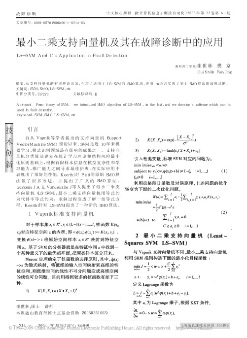
技术创新中文核心期刊《微计算机信息》(测控自动化)2006年第22卷第6-1期360元/年邮局订阅号:82-946《现场总线技术应用200例》故障诊断最小二乘支持向量机及其在故障诊断中的应用LS-SVMAndIt’sApplicationinFaultDetection(南阳理工学院)崔世林樊京Cui,ShilinFan,Jing摘要:从支持向量机的有关理论出发,介绍了适用于LS-SVM的SMO算法,并用c#语言实现了基于SMO算法的故障诊断。
关键词:SVM;SMO;LS-SVM;c#中图分类号:TP273文献标识码:BAbstract:FromtheoryofSVM,weintroducedSMOalgorithmofLS-SVM.inthelast,andwedevelopasoftwarewhichcanbuusedinfaultdetection.keyword:SVM;SMO;LS-SVM;c#文章编号:1008-0570(2006)06-1-0214-03引言自从Vapnik等学者提出的支持向量机(SupportVectorMachineSVM)理论以来,SVM是近10年来机器学习、模式识别领域最有影响的成果之一。
支持向量机分类算法建立在统计学习理论和结构风险最小化原则基础上,根据有限样本信息在模型复杂性和学习能力、推广能力之间寻求最佳折衷,在实际应用中表现出了很好的性能,Keerthi对Platt的原始SMO算法做了很多改进,并提出了广义的SMO算法。
SuykensJAK、VandewalleJ等人提出了最小二乘支持向量机(LS-SVM),最小二乘支持向量机用等式约束代替不等式约束,求解过程变成了解一组等式方程。
Keerthi针对LS-SVM提出了一种新的SMO算法。
1Vapnik标准支持向量机对于样本集,核函数K(xi,xj)对应特征空间z的内积,即。
变换将原始空间样本映射到特征空间z。
利用Matlab最小二乘法对牵引变电所接地网故障诊断的研究摘要:牵引变电所接地网埋设在地下,由于土壤的腐蚀或施工质量问题,导致接地性能变坏,威胁着牵引供电的安全稳定运行。
本文将牵引变电所接地网近似等效成纯电阻网络,根据接地网的拓扑结构和接地引线间电压的测量数据,建立故障诊断的方程组,利用matlab求解该诊断方程组,得到接地网各支路电阻的变化值,进而判断接地网的腐蚀程度,找到故障所在位置。
通过仿真计算,验证了本文接地网故障诊断方法的有效性和实用性。
关键词:接地网;最小二乘法;故障诊断引言接地网是牵引变电所重要设备,需要同时满足工作接地、保护接地与防雷接地的要求。
它不仅为牵引变电所内各种电气设备提供一个公共的电位参考点,而且在系统故障时还能迅速排泄故障电流,并防止地电位异常升高,确保跨步电压、接触电压和转移电压在容许的安全范围内,保障人身和设备安全,而在发生雷电时能将雷电流迅速泄入大地,使避雷器附近的物体得到保护,所以接地网接地性能的优劣直接关系到变电站所工作人员的人身安全及设备的正常运行,合格的接地网在电力系统安全运行中具有十分重要的作用[1]。
许多电气事故都是由于接地装置的缺陷引起的。
接地装置的缺陷原因有两个方面:一种是构成接地网的支路导体常常因施工时焊接不良或漏焊、接地短路电流的电动力作用和土壤的腐蚀等原因,使得接地引线出现腐蚀、甚至断裂或与接地网导体之间电气连接不良;另一种是构成接地网的支路导体深埋在地下,运行条件恶劣,特别是在一些潮湿和有害气体存在的地方,或土壤呈酸性的地方容易发生腐蚀,使得接地网导体出现不同程度的腐蚀、甚至断裂,接地性能变差,不能满足电力系统安全运行的要求。
由于施工工艺或金属腐蚀所造成的接地网电气连接故障,其带来的安全问题时有发生。
目前国内外学者已有不少研究成果。
本文根据牵引变电所接地网结构,利用MATLAB搭建其仿真电路,通过仿真测试,运用最小二乘法进行关联矩阵运算,得到相关诊断结果。
Artificial Immune Based Support Vector Machine Algorithm for Fault Diagnosis of Induction Motors İ. AYDIN1, Student Member, IEEE, M. KARAKÖSE2, E. AKIN3, Member IEEE1Computer Technology and Programming Education ProgramKemaliye H. A. AKIN Technical Vocational School of Higher EducationErzincan University, 24600, Kemaliye, Erzincan, Turkey2, 3Computer Engineering DepartmentFırat University, 23119, Elazığ, Turkey{iaydin, mkarakose, eakin}@.trAbstract-The use of induction motors is widespread in industry. Many researchers have studied the condition monitoring and detecting the faults of induction motors at an early stage. Early detection of motor faults results in fast unscheduled maintenance. In this study, a new artificial immune based support vector machine algorithm is proposed for fault diagnosis of induction motors. Support vector machines (SVMs) have become one of the most popular classification methods in soft computing, recently. However, classification accuracy depends on kernel and penalty parameters. Artificial immune system has abilities of learning, memory and self adaptive control. The kernel and penalizes parameters of support vector machine are tuned using artificial immune system. The training data of support vector machine are extracted from three phase motor current. The new feature vector is constructed based on park’s vector approach. The phase space of this feature vector is constructed using nonlinear time series analysis. Broken rotor bar and stator short circuit faults are classified in combined phase space using support vector machines. The experimental data are taken from a three phase induction motor. One, two and three broken rotor bar faults and 10% short circuit of stator faults are detected successfully.Key words: Support vector machines, artificial immune system, time series analysis, fault detection and diagnosis, induction motors, stator and broken rotor bar faults.I. I NTRODUCTIONInduction motors are the most used motors in industry applications. These motors are utilized in petrochemical, domestic and mining industries [1]. Induction motors are also used in military, aerospace and nuclear plants and reliability is important in these applications. These motors are reliably and they present numerous advantage but operation in dusty environments wears away them. This wear causes failures any part of an induction motor. Most motor failures reduce production and interrupt the process [2]. Therefore, many researchers have been studying to reduce maintenance costs and prevent unscheduled downtimes for induction motors. The motor failures are concerned one of three induction motor components: rotor, bearing and stator. The stator and rotor faults are among 14% and 38% of all motor faults, respectively. Although thermal and vibration monitoring have been used for fault diagnosis, motor current has been observed in the most of recent research [3].Parameter estimation and other model based techniques have been used for fault diagnosis and monitoring. These techniques are based on mathematical model of motor and require a deep knowledge about motor components.The fault diagnosis and monitoring of induction motors have been done using artificial intelligence techniques in recent years. These techniques require minimum motor configuration intelligence and any modeling of motor is not required [4]. By using these techniques, motor faults can be detected without an expert. Artificial intelligence techniques usually use current, voltage, speed, vibration signals of an induction motor for fault diagnosis. Fault detection based on motor current relies on amplitudes of frequency components in the current spectrum. Ondel et al. [5] have proposed k-nearest neighbor method for broken rotor bar faults. They have used three phase currents and voltages of an induction motor. One, two and three broken rotor bar faults have been detected under four different load conditions. Artificial neural networks and support vector machines have been compared for bearing fault diagnosis [6]. Bearing faults of an induction motor have been detected using time domain vibration signals. Zhitong et al. [7] have used support vector machines to detect broken rotor bar faults. Motor current signature analysis has been used to extract the features for inputs of support vector machines in their study. A fault diagnosis and monitoring method based on artificial intelligence method has been developed for broken rotor bar and stator faults detection [8]. A new feature vector called as envelope has been achieved using three phase stator current and slip computation. Phase space of this vector is formed using nonlinear time series analysis method. Motor faults have been classified using Bayesian classification algorithm. Aydın et al. [9] have proposed a time series data mining algorithm for broken rotor bar faults. In their study, feature data are extracted from three phase motor currents. One, two and three broken rotor bar faults are diagnosed at four different speeds. In this study, a new fault diagnosis algorithm based on artificial immune and support vector machines is proposed for broken rotor bars and stator faults. Previous fault detection algorithms based on artificial intelligence have monitored minimum two signals for fault detection. Motor current signature analysis is the most used method to detect broken rotor bar faults, but this method requires motor speed for slip1-4244-0891-1/07/$20.00 ©2007 IEEEcomputation and fails for motors with feeding PWM. Our method needs only three phase motor current for fault diagnosis. The kernel and penalize parameter of support vector machines affect performance of this classification method. The optimal values of these parameters have been tuned using artificial immune method.II. PROPOSED ARTIFICIAL IMMUNE BASED SUPPORT VECTOR MACHINE ALGORITHM FOR FAULT DIAGNOSIS OF INDUCTIONMOTORSBroken rotor bars and stator faults have been detected using artificial immune based support vector machine algorithm. One, two and three broken rotor bar faults and stator faults are recognized under four different operation speeds. The proposed method for classification of broken rotor bar faults needs three phase motor currents.A. Data Preprocessing and Obtaining of Feature VectorThe features of broken rotor bar and stator faults are extracted from three phase motor currents. Three phase motor currents are transformed to two park’s vector components. The new feature vector is constructed using these park’s vector components. Park’s vector approach is used to achieve a 2D representation of phase currents of a three phase induction motor. Park’s vector approach is given in (1).cb Ic b a I qd 2121616132−=−−=(1)Under ideal conditions, Park’s vector transformation of balanced three phase currents is shown in (2).2sin(26)sin(26max max πωω−==t I I t I I q d (2)Where I max is the supply phase current maximum value andω is the supply frequency. The Park’s vector is a circularpattern centered on the origin of the coordinates.The proposed fault classification scheme is given in Fig. 1.Park’s vector components are achieved from three phasemotor current and they are termed as I d and I q . The newfeature vector I o is constituted using these park’s vectorcomponents. The feature vector is shown in Fig. 2. After feature vector have been achieved, phase space of feature vector is constructed. The nonlinear time series analysis examines a time series in a phase space [10]. Time delay τ and embedding dimension d are important parameters in constituting a reconstructed phase space or briefly called phase space. For instance, when 2=τ and d=3, the vector ),,(24t t t t x x x X −−=is a point in phase space. Fig. 1. Fault classification scheme.Fig. 2. The new feature vector.Mutual information is used estimating the time delay andfalse nearest neighbor is used determining the embedding dimension. The details of these methods are given in [11]. B. Support Vector Machines (SVMs) SVMs are two classes classification method based on statistical learning theory [12]. For n-dimensional space, input data x i (i=1….k) belongs to class 1 or class 2 and the associated labels be -1 for class 1 and +1 for class 2. If the input data can be separated linearly, the separation hyper plane can be shown in (3). b x w X f T +=)( (3) Where w is n-dimensional weight vector and b is scalar multiplier or bias value. This equation finds a maximum margin to separate positive class from negative class. The decision function is shown in (4). )sgn()(b x w x f T +=(4)If two classes can be separated linearly, the hyper plane that satisfies maximum margin between two classes is found by solving (5). An example for linearly separable data is shown in Fig. 3. ⎪⎭⎪⎬⎫⎪⎩⎪⎨⎧≥+0)(||||212b x w y to Subject w Minimize i i i (5) When the parameters of SVM are well tuned, classificationperformance is increased. SVM training is done by solvingthe optimization problem in (5).⎪⎪⎪⎪⎭⎪⎪⎪⎪⎬⎫⎪⎪⎪⎪⎩⎪⎪⎪⎪⎨⎧=≥=−=∑∑∑===ki for y to subject x x K y y L imize i ki i i k i k j i j i j i j i i ....100),(21)(max 110,αααααα (6)Where K(x i ,x j ) is kernel function, i α are Lagrange multipliers. When the data can not be separated linearly,kernel function mapping changes according to (7).ij j i j i C x x K x x K δ1),(),(+= (7) Where C is penalize parameter and appropriate value of this parameter increase the classification performance. ij δ is Kronecker symbol. In this study, radial based kernel functionis used and this function is given in (8).))2/(exp(),(22σji j i x x x x K −−= (8)Where σis kernel parameter and this parameter affects distributing complexity of data in the feature space.Fig. 3. Hyper plane and support vectors.C. Artificial Immune System and Parameters Optimization of SVMs The immune system is an efficient self-defense method that guards the human body from foreign antigens or pathogens [13]. Artificial immune system is an emerging soft computingmethod inspired by natural immune system. This method is used in pattern recognition, classification, optimization and anomaly detection problems. Clonal selection is an artificial immune algorithm that is used for optimization problems.Clonal selection has not crossover operator, so this method is different from genetic algorithm. Affinity proportionalreproduction and affinity maturation are two distinctiveproperties of clonal selection. Because of these properties,clonal selection converges faster than genetic algorithm anddoesn’t catch local minimum. In this study, optimal parameters of support vector machine are selected using clonal selection. Each antibody is coding as binary string. Its construction is shown in Fig. 4. The proposed clonal selection algorithm is given in Fig. 5. Kernel σ and penalize parameters are selected in the range of [0.1, 2.55] and [1, 255], respectively. Precision of kernel σis 0.1 and penalize parameter is 1. The length of coding is selected as eight bits for each parameter. The mutation rate has been selected as 0.5. Affinity of each antibody iscalculated according to (9).)m e *100100max()antibody (f −= (9)Where e is number of misclassified data and m is length ofdata. It is selected n 1 highest affinity elements of population and generated clones of these individuals proportionally to their affinity with the antigen. If affinity of an individual ishigh, then clones of it are high.Fig. 4. Binary coding of antibodiesFig. 5. Clonal selection.Mutation rate of an individual is inversely proportional of its affinity. In this study inverse of an exponential function is used to establish a relationship between the mutation rate and the normalized affinity. This approach is given in (10). )exp()(**sa a m −= (10)Where a * is normalized affinity and can be determined bya *=a/a max . The control of smoothness is done by parameter sand is selected as 4 in our study.III. EXPERIMENTAL RESULTSWe performed experiments on an actual induction motorfor our analyses. The characteristics of the three phase induction motor used in our experiment are listed in Table I. The motor was tested with a healthy rotor, 10% stator short-circuit fault and with a faulty rotor that had one, two and three broken rotor bars. The diagram of experimental prototype is depicted in Fig. 6. The motor phase currents are saved with 3 kHz sampling frequency for duration 3 seconds. The supply voltages of the each motor condition are 380, 340, 300 and 260 V, respectively. Three phase motor currents, park’s vector component and feature vector are given in Fig. 7 for one broken rotor bar fault supplying with 300 V.TABLE IINDUCTION MOTOR CHARACTERISTIC USED IN THEEXPERIMENTDescription Value Power 0.37 kW Input Voltage 380 V Full Load Current 1.2 A Supply Frequency50 HzNumber of Poles4 Number of Rotor bars 22 Full Load Speed 1390 rpmFig. 6. A diagram of experimental prototype .After the feature vector is achieved, phase space of each condition has been constructed. For phase space, embedding dimension d is selected as two and time delay τ is selected as four by using false nearest neighbor and mutual information methods, respectively. The phase space of healthy motor is shown in Fig. 8. After phase space is constructed for eachmotor data, these phase space are combined as shown in Fig. 9. The artificial immune based SVM method for fault classification algorithm is applied in this phase space. The performance of clonal selection which separates the healthy phase space and one broken rotor bar faults is given in Fig. 10.Fig. 7. Phase currents, Park’s vector component and feature vector.Fig. 8. Healthy motor phase space.Fig. 9. Combined phase space.IterationF i t n e s sFig. 10. Clonal selection performance.SVM is normally a two class classification method. We have used one to other classification method for multiple classifications. The results of classification are given in table 2. The average performance of proposed method is %98.85 and only three phase motor currents are used. The most used methods in literature for stator and rotor faults are based on motor current signature analysis. This method needs motor slip computation to detect these faults. Clonal selection algorithm finds optimal kernel and penalize parameters at e few iteration as shown at Fig. 10.Fig. 11. SVM result with optimal kernel and penalize parameters.TABLE IIRESULTS OF ARTIFICIAL IMMUNE BASED SVM ALGORITHM FORFAULT CLASSIFICATION.Class NSV σ C AccuracyRate (%)CHB1 11 0.27 213 99.00 CHB2 12 0.17 159 99.00 CHB3 15 1.38 140 97.50 CHSF 13 0.38 108 99.00 CB1B2 9 0.38 242 99.00 CB1B3 4 0.63 88 99.00 CB1SF 4 1.01 32 99.00 CB2B3 5 0.45 244 99.00 CB2SF 16 0.19 140 99.00CB3SF 4 0.99 47 99.00 Average Accuracy Rate 98.85Broken Bar FaultsPark vector’s approach has been used for stator faults. But this method uses all of motor current. But our method uses only data relevant to fault and less data uses for fault classification.IV. CONCLUSIONThe stator and rotor faults in an induction motor have been detected using three phase motor currents. The park’s vector components have been extracted from three phase motor currents and new feature vector have been constructed from these components. The healthy and faulty motor conditions are classified in combined phase space using artificial immune based SVM algorithm. The optimal parameters of SVM are obtained using clonal selection algorithm. The motor currents have been taken an actual experimental setup and success results have been obtained.REFERENCES[1]B. Ayhan, M. Y. Chow and M. H. Song, “Multiple Discriminant Analysis and Neural Network-Based Monolith and Partition Fault-Detection Schemes for Broken Rotor Bar in Induction Motors”, IEEE Transactions on Industrial Electronic, Vol. 53, No. 4, pp. 1298-1308, August 2006.[2]M. Haji, H. A. Toliyat, “Pattern Recognition- A Technique for Broken Rotor Fault Detection ‘Eccentricity and Broken Bar Fault”, IEEE Thirty-Six Industry Applications Conference, Vol. 3, pp. 1572-1578, 2001.[3]M. E. H. Benbouzid and G.B. Kliman, “What Stator Current Processing-based Technique to Use for Induction Motor Rotor Faults Diagnosis?”, IEEE Transactions on Energy Conversion, Vol. 18, Issue. 2, pp. 238-244, June 2003.[4]F. Filippetti,G. Franceschini, C. Tassoni, and P. Vas, “Recent Developments of Induction Motor Drives Fault Diagnosis Using AI Techniques”, IEEE Transaction on Industrial Electronics, Vol. 47, No.5, pp. 994-1004, October 2000.[5]O. Ondel, E. Boutleux and G. Clerc, “A Method to Detect Broken Rotor Bars in Induction Machine Using Pattern Recognition Techniques”, IEEE Transactions on Industry Applications, Vol. 42, No. 4, pp. 916-923, July/Augst 2006.[6]B. Samanta, K. R. Al-Balushi and S. A. Al-Araimi, “Artificial Neural Networks and Support Vector Machines with Genetic Algorithm for Bearing Fault Detection”, Engineering Applications of Artificial Intelligence, Vol. 16, Issues 7-8, pp. 657-665, October-December 2003.[7]C. Zhitong, F. Jiazhong; C. Hongpingn; H. Guoguang, E. Ritchie, “Support Vector Machine Used to Diagnose the Fault of Rotor Broken Bars of Induction Motors”, IEEE Electrical Machines and Systems (ICEMS), Vol. 2, pp. 891 – 894, 2003.[8] Aderiano M. da Silva, “Induction Motor Fault Diagnostic and Monitoring Methods”, M.S. Thesis, Marquette University, Milwaukee, WI, 2006.[9] Aydın İ., KARAKÖSE M., AKIN E., “A Simple and Efficient Method for Fault Diagnosis Using Time Series Data Mining”, IEEE Electrical Machines and Drives Conference (IEMDC07), 597-600, 2007.[10] H. Kantz and T. Schreiber, “Nonlinear Time Series Analysis”, Cambridge: Cambridge University Press, 1997.[11]X. Feng, H. Huang, “A Fuzzy-Set-Based Reconstructed Phase Space Method for Identification of Temporal Patterns in Complex Time Series”, IEEE Transactions on Knowledge and Data Engineering, Vol. 17, No. 5, pp. 601-613, May 2005.[12] N. Cristianini and J. Shawe-Taylor, “An Introduction to Support Vector Machines and Other Kernel-based Learning Methods”, Cambridge University Press, 189 p., 2000.[13]L. N. De Castro and J. Timmis, “Artificial Immune Systems: A New Computational Intelligence Approach”, Springer Verlag, New York, USA, 2002.。