Appendix --Pressure Vessel Picture (1)
- 格式:doc
- 大小:20.10 MB
- 文档页数:31

HY10-1632-M2.3/USLabeling & StampingBladder AccumulatorsHY10-1632-M2.2/US Pre-Charging Instructions Bladder Accumulators If you have questions about the information contained inthis Maintenance & Installation Guide, please contact:Accumulator & Cooler Division - Americas phone 815 636 4100/accumulatorThe information specified in this guide serves to help understand how to install & maintain the product. The information given does not release the user from their own judgment and obligation of verification. The natural process of wear and aging also impacts how easily a product can be serviced.Extra care is taken in the preparation of this literature, but Parker is not responsible for any inadvertenttypographical errors or omissions. Information in this guide is only accurate as of the date of this publication. For a more current information base, please consult the Parker Accumulator & Cooler Division website at: /accumulatorMachesney Park, Illinois10711 N. Second Street, Machesney Park, Il 61115© Copyright 2016 Parker Hannifin Corporation. All rights reserved.Santa Fe Springs, California14087 Borate Street, Santa Fe Springs, CA 90670Offer of SaleThe items described in this document are hereby offered for sale by Parker Hannifin Corporation, its subsidiaries or its authorized distributors. This offer and its acceptance are governed by the provisions in the “Offer of Sale.”Main Product Label DetailAll BA Series Accumulators conform to ASME Boilerand Pressure Vessel Code Section VIII, Division 1 andthe European Pressure Equipment Directive 2014/68/EU(formerly 97/23/EC). Many of the accumulators in theBA Series are also Australian and Canadian registered.Each of the design codes and standards require specialinformation on the labels and stamps.Serial number of the specific accumulator.The internal gas capacity of the accumulator.Parker’s sales order number for the manufacturing lot.This helps customer service rapidly answer anyquestions pertaining to the specific accumulator.Temperature range the internal sealcomponents & bladder will continuouslymeet without rapid degradation.The year the accumulator was manufactured.The customer specified nitrogen pre-charge pressure.If no pre-charge is specified by the customer, this willbe left blank. There will still be a holding charge of29 PSIg (2 bar) max inside the accumulator.Parker’s CE registration number per PED 2014/68/EU(formerly 97/23/EC). If the vessel pressure x volume(PS x V) ratio is less than 50, then the accumulator willbe marked SEP for Sound Engineering Practice perArticle 4.3. (Formerly Article 3.3 under 97/23/EC.)Reminder that all ASME information is stampedon shell.Parker’s manufacturing address.Canadian & Australian Label DetailCanadian Stamping DetailASME Shell Stamping DetailCE Shell Stamping DetailSUPPLIERSUPPLIERSUPPLIER MAWP 3000 PSI AT 200°F V5GHY10-1632-M2.3/US 10/2016© 2016 Parker Hannifin CorporationParker Hannifin CorporationAccumulator & Cooler Division10711 N Second StreetMachesney Park, IL 61115phone 815 636 4100。
APPENDIX W —NONMANDATORYForm U-3A02FORM U-3MANUFACTURER’S CERTIFICATE OF COMPLIANCECOVERING PRESSURE VESSELS TO BE STAMPED WITH THE UM SYMBOL,SEE U-1(j)As Required by the Provisions of the ASME Code Rules,Section VIII,Division 11.Manufactured and certified by F1(Name and address of Manufacturer)2.Manufactured for F2(Name and address of Purchaser)3.Location of installation F56F3(Name and address)4.Type:F4F5F6F8(Horiz.,vert.,or sphere)(Tank,separator,etc.)(Capacity)(Mfg’s.serial No.)F9F10(CRN)(Drawing No.)(Year built)5.ASME Code,Section VIII,Div.1F13F14[Edition and Addenda (date)](Code Case No.)6.Shell(a)No.of course(s):(b)Overall length (ft &in.):F16F17Course(s)Material Thickness Long.Joint (Cat.A)Circum.Joint (Cat.A,B,&C)Heat Treatment No.Diameter,in.Length (ft &in.)Spec./Grade or TypeNom.Corr.TypeFull,Spot,NoneEff.TypeFull,Spot,NoneEff.Temp.TimeF18F19F20F21F22F23F24F25F26F277.Heads:(a)(b)F 20F27(Mat’l Spec.No.,Grade or Type)(H.T.—Time &Temp.)(Mat’l Spec.No.,Grade or Type)(H.T.—Time &Temp.)Thickness Radius Side to Pressure Category A Location (Top,Elliptical Conical HemisphericalFlat Bottom,Ends)Min.Corr.CrownKnuckleRatio Apex Angle RadiusDiameterConvexConcaveTypeFull,Spot,NoneEff.F28F22F29F30F31(a)(b)If removable,bolts used (describe other fastening)F32(Mat’l Spec.No.,Grade,Size,No.)8.Type of jacketJacket closureF33F34(Describe as ogee &weld,bar,etc.)If bar,give dimensions;if bolted describe or sketch9.MAWP psi at max.temp.F.Min.design metal temp. F atpsi.F 35F36F37(internal)(external)(internal)(external)10.Impact testat test temperature ofЊF.F38F38[Indicate yes or no and the component(s)impact tested]11.Hydro.,pneu.,or comb.test press.Proof testF39F4012.Nozzles,inspection,and safety valve openings:MaterialNozzle Thickness How Attached PurposeDiameterFlangeReinforcementLocation(Inlet,Outlet,Drain,etc.)No.or SizeTypeNozzleFlangeNom.Corr.MaterialNozzleFlange(Insp.Open.)F20F20F41F42F43F44F45F46F47F48F 49F48F 49F5013.Supports:SkirtLugsLegsOthersAttachedF51F51F51F51F51(Yes or no)(No.)(No.)(Describe)(Where and how)14.Manufacturer’s Partial Data Reports properly identified and signed by Commissioned Inspectors have been furnished for the following items ofthe report:(List the name of part,item number,mfg’ and identifying number)F5215.Remarks:F53CERTIFICATE OF SHOP COMPLIANCEF59We certify that the statements made in this report are correct and that all details of design,material,construction,and workmanship of this vessel conform to the ASME Code for Pressure Vessels,Section VIII,Division 1.UM Certificate of Authorization No.Expires DateNameSigned(Manufacturer)(Representative)This form (E00111)may be obtained from the Order Dept.,ASME,22Law Drive,Box 2300,Fairfield,NJ 07007-2300.Form U-42001SECTION VIII—DIVISION1FIG.W-3.1EXAMPLE OF THE USE OF FORM U-4。
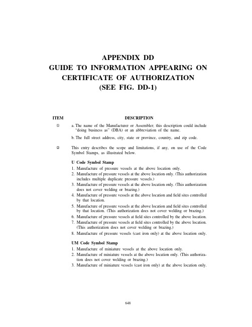
APPENDIX DDGUIDE TO INFORMATION APPEARING ON CERTIFICATE OF AUTHORIZATION(SEE FIG.DD-1)ITEM DESCRIPTION① a.The name of the Manufacturer or Assembler;this description could include“doing business as”(DBA)or an abbreviation of the name.b.The full street address,city,state or province,country,and zip code.②This entry describes the scope and limitations,if any,on use of the CodeSymbol Stamps,as illustrated below.U Code Symbol Stamp1.Manufacture of pressure vessels at the above location only.2.Manufacture of pressure vessels at the above location only.(This authorizationincludes multiple duplicate pressure vessels.)3.Manufacture of pressure vessels at the above location only.(This authorizationdoes not cover welding or brazing.)4.Manufacture of pressure vessels at the above location andfield sites controlledby that location.5.Manufacture of pressure vessels at the above location andfield sites controlledby that location.(This authorization does not cover welding or brazing.)6.Manufacture of pressure vessels atfield sites controlled by the above location.7.Manufacture of pressure vessels atfield sites controlled by the above location.(This authorization does not cover welding or brazing.)8.Manufacture of pressure vessels(cast iron only)at the above location only.UM Code Symbol Stamp1.Manufacture of miniature vessels at the above location only.2.Manufacture of miniature vessels at the above location only.(This authoriza-tion does not cover welding or brazing.)3.Manufacture of miniature vessels(cast iron only)at the above location only.648FIG.DD-1SAMPLE CERTIFICATE OF AUTHORIZATION650。
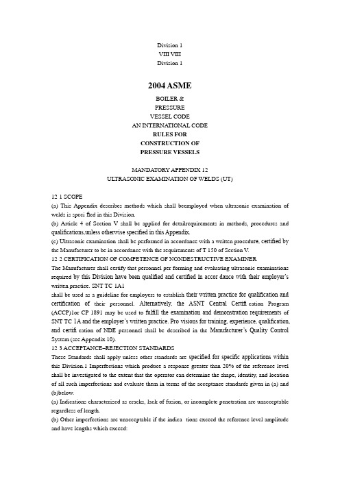
Division 1VIII VIIIDivision 12004 ASMEBOILER &PRESSUREVESSEL CODEAN INTERNA TIONAL CODERULES FORCONSTRUCTION OFPRESSURE VESSELSMANDATORY APPENDIX 12ULTRASONIC EXAMINA TION OF WELDS (UT)12-1 SCOPE(a) This Appendix describes methods which shall beemployed when ultrasonic examination of welds is speci-fied in this Division.(b) Article 4 of Section V shall be applied for detailrequirements in methods, procedures and qualifications,unless otherwise specified in this Appendix.(c) Ultrasonic examination shall be performed in accordance with a written procedu re, certified by the Manufacturer to be in accordance with the requirements of T-150 of Section V.12-2 CERTIFICATION OF COMPETENCE OF NONDESTRUCTIVE EXAMINERThe Manufacturer shall certify that personnel per-forming and evaluating ultrasonic examinations required by this Division have been qualified and certified in accor-dance with their employer’s written practice. SNT-TC-1A1shall be used as a guideline for employers to establish their written practice for qualification and certification of their personnel. Alternatively, the ASNT Central Certifi-cation Program (ACCP)1or CP-1891 may be used to fulfill the examination and demonstration requirements of SNT-TC-1A and the employer’s written practice. Pro-visions for training, experience, qualification, and certifi-cation of NDE personnel shall be described in the Manufacturer’s Quality Control System (see Appendix 10).12-3 ACCEPTANCE–REJECTION STANDARDSThese Standards shall apply unless other standards are specified for specific applications within this Division.1 Imperfections which produce a response greater than 20% of the reference level shall be investigated to the extent that the operator can determine the shape, identity, and location of all such imperfections and evaluate them in terms of the acceptance standards given in (a) and (b)below.(a) Indications characterized as cracks, lack of fusion, or incomplete penetration are unacceptable regardless of length.(b) Other imperfections are unacceptable if the indica- tions exceed the reference level amplitude and have lengths which exceed:(1)1⁄4 in. (6 mm) for t up to 3⁄4 in. (19 mm);(2)1⁄3t for t from 3⁄4 in. to 21⁄4 in. (19 mm to 57 mm);(3)3⁄4 in. (19 mm) for t over 21⁄4 in. (57 mm).where t is the thickness of the weld excluding any allow-able reinforcement. For a butt weld joining two members having different thicknesses at the weld, t is the thinner of these two thicknesses. If a full penetration weld includes a fillet weld, the thickness of the throat of the fillet shall be included in t.12-4 REPORT OF EXAMINATIONThe Manufacturer shall prepare a report of the ultra-sonic examination and a copy of this report shall be retained by the Manufacturer until the Manufacturer’s Data Report has been signed by the Inspector. The report shall contain the information required by Section V. In addition, a record of repaired areas shall be noted as well as the results of the reexamination of the repaired areas.The Manufacturer shall also maintain a record of all reflections from uncorrected areas having responses that exceed 50%of the reference level. This record shall locate each area, the response level, the dimensions, the depth below the surface, and the classification。


石化3503最新规范1范围本标准明确了石油化工建设工程项日从工程开工到工程交工验收过程中形成的设计、采购、施工及检测等交工技术文件的要求。
本标准适用于石油化工新建、扩建和改建工程项目的交工技术文件编制、整理和交付。
2规范性引用文件下列文件对于本标准的应用是必不可少的。
凡是注口期的引用文件,仅注口期的版本适用于本标准。
凡是不注日期的引用文件,其最新版本(包括所有的修改单)适用于本标准。
GB/T10609.3技术制图复制图的折叠方法GB/T11822科学技术档案案卷构成的一般要求GB/T14689技术制图图纸幅面和格式GB50300建筑工程施工质量验收统一标准GB/T50328建设工程文件归档规范DA/T28国家重大建设项目文件归档要求与档案整理规范SH/T3508石油化工安装工程施工质量验收统一标准SH/T3903右油化工建设工程项目监理规范SH/T3904石油化工建设工程项日竣工验收规范3术语和定义GB/T50328、SH/T3903和SH/T3904确立的及以下术语和定义适用于本标准。
3.1交工技术文件hand over technical documentation工程总承包单位或设计、采购、施上、检测等承包单位在建设工程项目实施过程中形成并在工程交工时移交建设单位的工程实现过程、使用功能符合要求的证据及竣工图等技术文件的统称,是建设工程文件归档的组成部分。
质量证明文件原件original quality certificate加盖生产厂检验专用章或质量证明专用章的产品质量证明文件或由供应商、采购单位在产品质量证明文件复印件上加盖确认印章的延续性质量证明文件。
3.3项目管理单位project management contractor按照合同约定和建设单位授权,代表建设单位为工程项日实施各阶段提供工程项日管理服务并承担相应管理责任的工程项目管理企业或经建设单位批准成立的项目管理机构(包括PM、PMC、IPMT等项目管理模式下的项目管理机构)。
Mandatory AppendicesA02MANDATORY APPENDICESAppendix1Supplementary Design Formulas (313)Appendix2Rules for Bolted Flange Connections With Ring Type Gaskets (329)Appendix3Definitions (350)Appendix4Rounded Indications Charts Acceptance Standard for RadiographicallyDetermined Rounded Indications in Welds (353)Appendix5Flanged and Flued or Flanged Only Expansion Joints..........................360.1 Appendix6Methods for Magnetic Particle Examination(MT) (361)Appendix7Examination of Steel Castings (363)Appendix8Methods for Liquid Penetrant Examination(PT) (366)Appendix9Jacketed Vessels (368)Appendix10Quality Control System (377)Appendix11Capacity Conversions for Safety Valves (380)Appendix12Ultrasonic Examination of Welds(UT) (384)Appendix13Vessels of Noncircular Cross Section (385)Appendix14Integral Flat Heads With a Large,Single,Circular,Centrally LocatedOpening (431)Appendix16Submittal of Technical Inquiries to the Boiler and Pressure VesselCommittee (438)Appendix17Dimpled or Embossed Assemblies (440)Appendix18Adhesive Attachment of Nameplates (452)Appendix19Electrically Heated or Gas Fired Jacketed Steam Kettles (453)Appendix20Hubs of Tubesheets and Flat Heads Machined From Plate (454)Appendix21Jacketed Vessels Constructed of Work-Hardened Nickel (455)Appendix22Integrally Forged Vessels (456)Appendix23External Pressure Design of Copper,Copper Alloy,and Titanium AlloyCondenser and Heat Exchanger Tubes With Integral Fins (458)Appendix24Design Rules for Clamp Connections (460)Appendix25Acceptance of Testing Laboratories and Authorized Observers for CapacityCertification of Pressure Relief Valves (467)Appendix26Pressure Vessel and Heat Exchanger Expansion Joints (469)Appendix27Alternative Requirements for Glass-Lined Vessels (481)Appendix28Alternative Corner Weld Joint Detail for Box Headers for Air-Cooled HeatExchangers (483)Appendix29Requirements for Steel Bars of Special Section for Helically WoundInterlocking Strip Layered Pressure Vessels (486)Appendix30Rules for Drilled Holes Not Penetrating Through Vessel Wall (489)Appendix31Rules for Cr–Mo Steels With Additional Requirements for Welding and HeatTreatment (491)FIG.1-4PRINCIPAL DIMENSIONS OF TYPICAL HEADS When P is known and t is desired,t p R(Y 1⁄3−1)p RoY1⁄3−1Y1⁄3(1)whereY p 2(SE+P) 2SE−PWhen t is known and P is desired,P p2SEY−1Y+2(2)whereY pR+t R3pR o R o−t3Symbols are as defined in UG-27and1-1.1-4FORMULAS FOR THE DESIGNFORMED HEADS UNDERINTERNAL PRESSURE(a)The formulas of this paragraph provide for design of formed heads of proportions other those given in UG-32,in terms of inside and outside diameter.(b)The symbols defined below are used in formulas of this paragraph(see Fig.1-4):t p minimum required thickness of head after form-ing,in.(mm)P p internal design pressure(see UG-21),psi(kPa)A021-4APPENDIX1—MANDATORY1-5TABLE1-4.2VALUES OF FACTOR M(Use Nearest Value of L/r;Interpolation Unnecessary)L/r 1.0 1.25 1.50 1.75 2.00 2.25 2.50 2.75 3.00 3.25 3.50 M 1.00 1.03 1.06 1.08 1.10 1.13 1.15 1.17 1.18 1.20 1.22 L/r 4.0 4.5 5.0 5.5 6.0 6.57.07.58.08.59.0M 1.25 1.28 1.31 1.34 1.36 1.39 1.41 1.44 1.46 1.48 1.50 L/r9.510.0010.511.011.512.013.014.015.016.0162⁄31 M 1.52 1.54 1.56 1.58 1.60 1.62 1.65 1.69 1.72 1.75 1.77 NOTE:(1)Maximum ratio allowed by UG-32(j)when L equals the outside diameter of the skirt of the head.orP p2SEt cos␣D o−0.8t cos␣(6)1-5RULES FOR CONICAL REDUCERSECTIONS AND CONICAL HEADSUNDER INTERNAL PRESSURE(a)The formulas of(d)and(e)below provide forthe design of reinforcement,if needed,at the cone-to-cylinder junctions for conical reducer sections andconical heads where all the elements have a commonaxis and the half-apex angle␣≤30deg.Subparagraph(g)below provides for special analysis in the designof cone-to-cylinder intersections with or without rein-forcing rings where␣is greater than30deg.In the design of reinforcement for a cone-to-cylinderjuncture,the requirements of UG-41shall be met.(b)NomenclatureA rL p required area of reinforcement at large end ofcone,in.2(mm2)A rs p required area of reinforcement at small end ofcone,in.2(mm2)A eL p effective area of reinforcement at large end in-tersection,in.2(mm2)A es p effective area of reinforcement at small end in-tersection,in.2(mm2)E s p modulus of elasticity of cylinder material,psi(kPa)E c p modulus of elasticity of cone material,psi(kPa)E r p modulus of elasticity of reinforcing ring mate-rial,psi(kPa)NOTE:The modulus of elasticity shall be taken from the applicableTable TM in Section II,Part D.When a material is not listed inthe TM tables,the requirements of U-2(g)shall be applied.E1p efficiency of longitudinal joint in cylinder.Forcompression(such as at large end of cone),E1p1.0for butt welds.E2p efficiency of longitudinal joint in cone.For com-pression,E2p1.0for butt welds.f1p axial load at large end due to wind,dead load,etc.,excluding pressure,lb/in.(kN/m)f2p axial load at small end due to wind,dead load,etc.,excluding pressure,lb/in.(kN/m)P p internal design pressure(see UG-21),psi(kPa)Q L p algebraical sum of PR L/2and f1,lb/in.(kN/m)Q s p algebraical sum of PR s/2and f2,lb/in.(kN/m)R s p inside radius of small cylinder at small end ofcone,in.(mm)R L p inside radius of large cylinder at large end ofcone,in.(mm)S s p allowable stress of cylinder material at designtemperature,psi(kPa)S c p allowable stress of cone material at design tem-perature,psi(kPa)S r p allowable stress of reinforcing ring material atdesign temperature,psi(kPa)t p minimum required thickness of cylinder atcone-to-cylinder junction,in.(mm)t c p nominal thickness of cone at cone-to-cylinderjunction,in.(mm)t r p minimum required thickness of cone at cone-to-cylinder junction,in.(mm)t s p nominal thickness of cylinder at cone-to-cylin-der junction,in.(mm)␣p half-apex angle of cone or conical section,deg.⌬p angle indicating need for reinforcement at cone-to-cylinder junction having a half-apex angle␣≤30deg.When⌬≥␣,no reinforcement is required at thejunction(see Tables1-5.1and1-5.2),deg.y p cone-to-cylinder factorp S s E s for reinforcing ring on shellp S c E c for reinforcing ring on cone1-52001SECTION VIII—DIVISION11-5 TABLE1-5.1VALUES OF⌬FOR JUNCTIONS AT THE LARGECYLINDER FOR␣≤30deg.P/S s E10.0010.0020.0030.0040.005⌬,deg.1115182123P/S s E10.0060.0070.0080.0091...⌬,deg.252728.530...NOTE:(1)⌬p30deg.for greater values of P/S s E1.TABLE1-5.2VALUES OF⌬FOR JUNCTIONS AT THE SMALLCYLINDER FOR␣≤30deg.P/S s E10.0020.0050.0100.02⌬,deg.46912.5P/S s E10.040.080.100.1251⌬,deg.17.5242730NOTE:(1)⌬p30deg.for greater values of P/S s E1.(c)For a cone-to-cylinder junction,the followingvalues shall be determined at large end and again atthe small end in order that both the large end and thesmall end can be examined:Determine P/S s E1and then determine⌬at the largeend and at the small end,as appropriate,from Tables1-5.1and1-5.2.Determine k:k p1when additional area of reinforcement is notrequiredp y/S r E r when a stiffening ring is required,butk is not less than1.0(d)Reinforcement shall be provided at the junctionof the cone with the large cylinder for conical headsand reducers without knuckles when the value of⌬obtained from Table1-5.1,using the appropriate ratioP/S s E1,is less than␣.Interpolation may be made inthe Table.The required area of reinforcement shall be at leastequal to that indicated by the following formula whenQ L is in tension:A rL p kQ L R LS s E11−⌬␣tan␣(1)**At the large end of the cone-to-cylinder juncture, the PR L/2term is in tension.When f1is in compression **For some of the terms of the above equation(s),it may be necessary to convert millimeters to meters to obtain a rational result in SI units.and the quantity is larger than the PR L/2term,the design shall be in accordance with U-2(g).The calcu-lated localized stresses at the discontinuity shall not exceed the stress values specified in1-5(g)(1)and(2).The effective area of reinforcement can be determinedin accordance with the following formula:A eL p(t s−t)ΊR L t s+(t c−t r)ΊR L t c/cos␣(2)Any additional area of reinforcement which is required shall be situated within a distance ofΊR L t s from the junction of the reducer and the cylinder.The centroidof the added area shall be within a distance of0.25؋ΊR L t s from the junction.(e)Reinforcement shall be provided at the junctionof the conical shell of a reducer without aflare andthe small cylinder when the value of⌬obtained from Table1-5.2,using the appropriate ratio P/S s E1,is lessthan␣.The required area of reinforcement shall be at least equal to that indicated by the following formula whenQ s is in tension:A rs pkQ s R sS s E11−⌬␣tan␣(3)**At the small end of the cone-to-cylinder juncture,the PR s/2term is in tension.When f2is in compressionand the quantity is larger than the PR s/2term,the design shall be in accordance with U-2(g).The calcu-lated localized stresses at the discontinuity shall not exceed the stress values specified in1-5(g)(1)and(2).The effective area of reinforcement can be determinedin accordance with the following formula:A es p0.78ΊR s t s[(t s−t)+(t c−t r)/cos␣](4)Any additional area of reinforcement which is requiredshall be situated within a distance ofΊR s t s from the junction,and the centroid of the added area shall be within a distance of0.25ΊR s t s from the junction.(f)Reducers not described in UG-36(e)(5),such as those made up of two or more conical frustums having different slopes,may be designed in accordance with(g). (g)When the half-apex angle␣is greater than30 deg.(0.52rad),cone-to-cylinder junctions without a knuckle may be used,with or without reinforcing rings,if the design is based on special analysis,such asthe beam-on-elastic-foundation analysis of Timoshenko, Hetenyi,or Watts and Lang.See U-2(g).When suchan analysis is made,the calculated localized stressesA02A02 A021-5APPENDIX1—MANDATORY1-6FIG.1-6SPHERICALLY DISHED COVERS WITH BOLTING FLANGESat the discontinuity shall not exceed the followingvalues.(1)(Membrane hoop stress)+(average discontinu-ity hoop stress)shall not be greater than1.5S,wherethe“average discontinuity hoop stress”is the averagehoop stress across the wall thickness due to the disconti-nuity at the junction,disregarding the effect of Poisson’sratio times the longitudinal stress at the surfaces.(2)(Membrane longitudinal stress)+(discontinuitylongitudinal stress due to bending)shall not be greaterthan S PS[see UG-23(e)].The angle joint(see3-2)between the cone andcylinder shall be designed equivalent to a double butt-welded joint,and because of the high bending stress,there shall be no weak zones around the angle joint.The thickness of the cylinder may have to be increasedto limit the difference in thickness so that the anglejoint has a smooth contour.1-6SPHERICALLY DISHED COVERS(BOLTED HEADS)(a)Circular spherical dished heads with boltingflanges,both concave and convex to the pressure andconforming to the several types illustrated in Fig.1-6,shall be designed in accordance with the formulaswhich follow.(b)The symbols used in the formulas of this para-graph are defined as follows:t p minimum required thickness of head plate afterforming,in.(mm)L p inside spherical or crown radius,in.(mm)r p inside knuckle radius,in.(mm)P p internal pressure(see UG-21)for the pressureon concave side,and external pressure for thepressure on convex side[see UG-28(f)],psi(kPa)S p maximum allowable stress value,psi(kPa)(seeUG-23)T pflange thickness,in.(mm)M o p the total moment,in.-lb(kN W m),determined asin2-6for heads concave to pressure and2-11for heads convex to pressure;except that forheads of the type shown in Fig.1-6sketch(d),H D and h D shall be as defined below,and anadditional moment H r h r(which may add or sub-tract)shall be included whereH r p radial component of the membrane loadin the spherical segment,lb(kN),actingat the intersection of the inside of the1-62001SECTION VIII—DIVISION11-6flange ring with the center line of thedished cover thicknessp H D cot1h r p lever arm of force H r about centroid offlange ring,in.(mm)H D p axial component of the membrane load inthe spherical segment,lb(kN),acting atthe inside of theflange ringp0.785B2Ph D p radial distance from the bolt circle to theinside of theflange ring,in.(mm)1p angle formed by the tangent to the centerline of the dished cover thickness at itspoint of intersection with theflange ring,and a line perpendicular to the axis of thedished coverp arc sinB2L+tNOTE:Since H r h r in some cases will subtract from the total moment, the moment in theflange ring when the internal pressure is zero may be the determining loading forflange design.A p outside diameter offlange,in.(mm)B p inside diameter offlange,in.(mm)C p bolt circle,diameter,in.(mm)(c)It is important to note that the actual value of the total moment M o may calculate to be either plus or minus for both the heads concave to pressure and the heads convex to pressure.However,for use in all of the formulas which follow,the absolute values for both P and M o are used.(d)Heads of the type shown in Fig.1-6sketch(a):(1)the thickness of the head t shall be determined by the appropriate formula in UG-32for pressure on concave side,and UG-33(a)(1)for pressure on convex side;(2)the head radius L or the knuckle radius r shall comply with the limitations given in UG-32;(3)theflange shall comply at least with the require-ments of Fig.2-4and shall be designed in accordance with the provisions of2-1through2-7for pressure on concave side,and2-11for pressure on convex side. (Within the range offlange standards listed in Table U-3,theflange and drillings may conform to the standards,and the thickness specified therein shall be considered as a minimum requirement.)(e)Heads of the type shown in Fig.1-6sketch(b) (no joint efficiency factor is required):(1)head thickness(a)for pressure on concave side,t p5PL6S(1)(b)for pressure on convex side,the head thick-ness shall be determined based on UG-33(c)using the outside radius of the spherical head segment;(2)flange thickness for ring gasketT pΊM o SB΄A+B A−B΅(2)**(3)flange thickness for full face gasketT p0.6ΊP S΄B(A+B)(C−B)A−B΅(3)NOTE:The radial components of the membrane load in the spherical segment are assumed to be resisted by itsflange.(Within the range offlange standards listed in Table U-3,theflange and drillings may conform to the standards,and the thickness specified therein shall be considered as a minimum requirement.)(f)Heads of the type shown in Fig.1-6sketch(c) (no joint efficiency factor is required):(1)head thickness(a)for pressure on concave side,t p5PL6S(4)(b)for pressure on convex side,the head thick-ness shall be determined based on UG-33(c)using the outside radius of the spherical head segment;(2)flange thickness for ring gasket for heads with round bolting holesT p Q+Ί1.875M o(C+B)SB(7C−5B)(5)** whereQ pPL4SC+B7C−5B****For some of the terms of the above equation(s),it may be necessary to convert millimeters to meters to obtain a rational result in SI units.1-6APPENDIX1—MANDATORY1-7(3)flange thickness for ring gasket for heads withbolting holes slotted through the edge of the headT p Q+Ί1.875M o(C+B)SB(3C−B)(6)**whereQ p PL4SC+B 3C−B(4)flange thickness for full-face gasket for heads with round bolting holesT p Q+ΊQ2+3BQ(C−B)L(7) whereQ p PL4SC+B 7C−5B(5)flange thickness for full-face gasket for heads with bolting holes slotted through the edge of the head T p Q+ΊQ2+3BQ(C−B)L(8) whereQ pPLC+B(6)the requiredflange thickness shall be T as calculated in(2),(3),(4),or(5)above,but in no case less than the value of t calculated in(1)above. (g)Heads of the type shown in Fig.1-6sketch(d) (no joint efficiency factor is required):(1)head thickness(a)for pressure on concave side,t p 5PL6S(9)(b)for pressure on convex side,the head thick-ness shall be determined based on UG-33(c)using the outside radius of the spherical head segment;**For some of the terms of the above equation(s),it may be necessary to convert millimeters to meters to obtain a rational result in SI units.(2)flange thicknessT p F+ΊF2+J(10) whereF pPBΊ4L2−B28S(A−B)andJ pM o SBA+B A−B(h)These formulas are approximate in that they do not take into account continuity between theflange ring and the dished head.A more exact method of analysis which takes this into account may be used if it meets the requirements of U-2.1-7LARGE OPENINGS INCYLINDRICAL SHELLS1-7(a)Openings exceeding the dimensional limits given in UG-36(b)(1)shall be provided with reinforce-ment that complies with the following rules.Two-thirds of the required reinforcement shall be within the following limits:1-7(a)(1)parallel to vessel wall:the larger of three-fourths times the limit in UG-40(b)(1),or equal to the limit in UG-40(b)(2);1-7(a)(2)normal to vessel wall:the smaller of the limit in UG-40(c)(1),or in UG-40(c)(2).1-7(b)Openings for radial nozzles that exceed the limits in UG-36(b)(1)1-7(b)(1)and which also are within the range defined by the following limits shall meet the require-ments in(b)(2),(3),and(4)below:(a)vessel diameters greater than60in.(mm) I.D.;(b)nozzle diameters which exceed40in.(mm) I.D.and also exceed3.4ΊRt;the terms R and t are defined in Figs.1-7-1and1-7-2;(c)the ratio R n/R does not exceed0.7;for nozzle openings with R n/R exceeding0.7,refer to(c) below and/or U-2(g).A021-72001SECTION VIII—DIVISION11-7FIG.1-7-1The rules are limited to radial nozzles in cylindricalshells that do not have internal projections,and do notinclude any analysis for stresses resulting from exter-nally applied mechanical loads.For such cases U-2(g)shall apply.1-7(b)(2)The membrane stress S m as calculatedby Eq.(1)or(2)below shall not exceed S,as definedin UG-37for the applicable materials at design condi-tions.The maximum combined membrane stress S mand bending stress S b shall not exceed1.5S at designconditions.S b shall be calculated by Eq.(5)below.1-7(b)(3)Evaluation of combined stresses frominternal pressure and external loads shall be made inaccordance with U-2(g).1-7(b)(4)For membrane stress calculations,usethe limits defined in Fig.1-7-1,and comply with thestrength of reinforcement requirements of UG-41.Forbending stress calculation,the greater of the limitsdefined in Fig.1-7-1or Fig.1-7-2may be used.Thestrength reduction ratio requirements of UG-41neednot be applied,provided that the allowable stress ratioof the material in the nozzle neck,nozzle forging,reinforcing plate,and/or nozzleflange divided by theshell material allowable stress is at least0.80.NOTE:The bending stress S b calculated by Eq.(5)is valid andapplicable only at the nozzle neck-shell junction.It is a primarybending stress because it is a measure of the stiffness required tomaintain equilibrium at the longitudinal axis junction of the nozzle-shell intersection due to the bending moment calculated by Eq.(3).Case A(See Fig.1-7-1)S m p PR(R n+t n+ΊR m t)+R n(t+t e+ΊR nm t n)A s(1)Case B(See Fig.1-7-1)S m p PR(R n+t n+ΊR m t)+R n(t+ΊR nm t n)A s(2)1-7APPENDIX 1—MANDATORY1-7FIG.1-7-2Cases A and B (See Fig.1-7-1or Fig.1-7-2)M p R 3n 6+R R n e P(3)**a p e +t/2(4)S b p Ma I(5)**1-7(b)(5)Nomenclature.Symbols used in Figs.1-7-1and 1-7-2are as defined in UG-37(a)and as follows:A s p shaded (cross-hatched)area in Fig.1-7-1,CaseA or Case B,in.2(mm 2)**For some of the terms of the above equation(s),it may be necessary to convert millimeters to meters to obtain a rational result in SI units.I p moment of inertia of the larger of the shadedareas in Fig.1-7-1or Fig.1-7-2about neutral axis,in.4(mm 4)a p distance between neutral axis of the shaded areain Fig.1-7-1or Fig.1-7-2and the inside of vessel wall,in.(mm)R m p mean radius of shell,in.(mm)R nm p mean radius of nozzle neck,in.(mm)e p distance between neutral axis of the shaded areaand midwall of the shell,in.(mm)S m p membrane stress calculated by Eq.(1)or (2),psi (kPa)S b p bending stress at the intersection of inside ofthe nozzle neck and inside of the vessel shell along the vessel shell longitudinal axis,psi (kPa)S y p yield strength of the material at test temperature,see Table Y-1in Subpart 1of Section II,Part D,psi (kPa)1-7(c)It is recommended that special consideration be given to the fabrication details used and inspectionA021-72001SECTION VIII—DIVISION11-8 employed on large openings;reinforcement often may beadvantageously obtained by use of heavier shell plate for avessel course or inserted locally around the opening;weldsmay be ground to concave contour and the inside corners ofthe opening rounded to a generous radius to reduce stressconcentrations.When radiographic examination of welds isnot practicable,liquid penetrant examination may be usedwith nonmagnetic materials and either liquid penetrant ormagnetic particle inspection with ferromagnetic materials.Ifmagneticparticleinspectionisemployed,theprodmethodis preferred.The degree to which such measures should beused depends on the particular application and the severityof the intended service.Appropriate proof testing may beadvisable in extreme cases of large openings approachingfull vessel diameter,openings of unusual shape,etc.1-8RULES FOR REINFORCEMENT OFCONE-TO-CYLINDER JUNCTIONUNDER EXTERNAL PRESSURE(a)The formulas of(b)and(c)below provide forthe design of reinforcement,if needed,at the cone-to-cylinder junctions for reducer sections and conical headswhere all the elements have a common axis and thehalf-apex angle␣≤60deg.Subparagraph(e)belowprovides for special analysis in the design of cone-to-cylinder intersections with or without reinforcing ringswhere␣is greater than60deg.In the design of reinforcement for a cone-to-cylinderjuncture,the requirements of UG-41shall be met.The nomenclature given below is used in the formulasof the following subparagraphs:A p factor determined from Fig.G and used to enterthe applicable material chart in Subpart3ofSection II,Part DA eL p effective area of reinforcement at large end in-tersection,in.2(mm2)A es p effective area of reinforcement at small end in-tersection,in.2(mm2)A rL p required area of reinforcement at large end ofcone,in.2(mm2)A rs p required area of reinforcement at small end ofcone,in.2(mm2)A s p cross-sectional area of the stiffening ring,sq in.(mm2)A T p equivalent area of cylinder,cone,and stiffeningring,sq in.(mm2),whereA TL pL L t s2+L c t c2+A s for large endA TS pL s t s+L c t c+A s for small endB p factor determined from the applicable materialchart in Subpart3of Section II,Part D formaximum design metal temperature,psi(kPa)[see UG-20(c)]D L p outside diameter of large end of conical sectionunder consideration,in.(mm)D o p outside diameter of cylindrical shell,in.(mm).(In conical shell calculations,the value of D sand D L should be used in calculations in placeof D o depending on whether the small end D s,or large end D L,is being examined.)D s p outside diameter at small end of conical sectionunder consideration,in.(mm)E1p efficiency of longitudinal joint in cylinder.Forcompression(such as at small end of cone),E1p1.0for butt welds.E2p efficiency of longitudinal joint in cone.For com-pression,E2p1.0for butt welds.E c p modulus of elasticity of cone material,psi(kPa)E r p modulus of elasticity of stiffening ring material,psi(kPa)E s p modulus of elasticity of shell material,psi(kPa)E x p E c,E r,or E sNOTE:The modulus of elasticity shall be taken from the applicableTable TM in Section II,Part D.When a material is not listed inthe TM tables,the requirements of U-2(g)shall be applied.f1p axial load at large end due to wind,dead load,etc.,excluding pressure,lb/in.(kN/m)f2p axial load at small end due to wind,dead load,etc.,excluding pressure,lb/in.(kN/m)I p available moment of inertia of the stiffeningring cross section about its neutral axis parallelto the axis of the shell,in.4(mm4)I′p available moment of inertia of combined shell-cone or ring-shell-cone cross section about itsneutral axis parallel to the axis of the shell,in.4(mm4).The nominal shell thickness t s shall beused,and the width of the shell which is takenas contributing to the moment of inertia of thecombined section shall not be greater than1.10ΊDt s and shall be taken as lying one-half oneach side of the cone-to-cylinder junction or ofthe centroid of the ring.Portions of the shellplate shall not be considered as contributingarea to more than one stiffening ring.CAUTIONARY NOTE:Stiffening rings may be subject to lateralbuckling.This should be considered in addition to the requirementsfor I s and I′s[see U-2(g)].I s p required moment of inertia of the stiffening ringcross section about its neutral axis parallel tothe axis of the shell,in.4(mm4)I′s p required moment of inertia of the combined1-8APPENDIX1—MANDATORY1-8 lated localized stresses at the discontinuity shall notexceed the stress values specified in1-5(g)(1)and(2).The effective area of reinforcement can determinedin accordance with the following formula:A es p0.55ΊD s t s[(t s−t)+(t c−t r)/cos␣](4)Any additional area of stiffener which is requiredshall be situated within a distance ofΊR s t s from thejunction,and the centroid of the added area shall bewithin a distance of0.25ΊR s t s from the junction.When the cone-to-cylinder or knuckle-to-cylinderjuncture is a line of support,the moment of inertiafor a stiffening ring at the small end shall be determinedby the following procedure.Step1.Assuming that the shell has been designedand D s,L s,and t are known,select a member to beused for the stiffening ring and determine cross-sectionalarea A TS.Then calculate factor B using the followingformula.If F s is a negative number,the design shallbe in accordance with U-2(g):B p3⁄4F s D s A TSwhereF s p PN+f2tan␣N p R s tan␣2+L s2+R L2−R s26R s tan␣**Step 2.Enter the right-hand side of theapplicable material chart in Subpart3of Section II,Part D for the material under consideration at the value of B determined by Step1.If different materials are used for the shell and stiffening ring,use the material chart resulting in the larger value of A in Step4below. Step 3.Move horizontally to the left to the material/temperature line for the design metal tempera-ture.For values of B falling below the left end of the material/temperature line,see Step5below.Step4.Move vertically to the bottom of the chart and read the value of A.Step5.For values of B falling below the left end of the material/temperature line for the design tempera-ture,the value of A can be calculated using the formula **For some of the terms of the above equation(s),it may be necessary to convert millimeters to meters to obtain a rational result in SI units.A p2B/E x.For value of B above the material/ temperature line for the design temperature,the designshall be either per U-2(g)or by changing the cone or cylinder configuration,stiffening ring location on the shell,and/or reducing the axial compressive force to reduce the B value to below or at the material/ temperature line for the design temperature.For valuesof B having multiple values of A,such as when Bfalls on a horizontal portion of the curve,the smallest value of A shall be used.pute the value of the required momentof inertia from the formulas for I s or I′s.For the circumferential stiffening ring only,I s pAD s2A TS14.0For the shell-cone or ring-shell-cone section,I′s pAD s2A TS10.9Step7.Determine the available moment of inertiaof the ring only I or the shell-cone or ring-shell-coneI′.Step8.When the ring only is used,I≥I sand when the shell-cone or ring-shell-cone is used:I′≥I′sIf the equation is not satisfied,a new section witha larger moment of inertia must be selected,and the calculation shall be done again until the equation is met.The requirements of UG-29(b),(c),(d),(e),and(f)and UG-30are to be met in attaching stiffening ringsto the shell.(d)Reducers not described in UG-36(e)(5),such as those made up of two or more conical frustums having different slopes,may be designed in accordance with(e).(e)When the half-apex angle␣is greater than60 deg.(1.1rad),cone-to-cylinder junctions without a knuckle may be used,with or without reinforcing rings,if the design is based on special analysis,such asthe beam-on-elastic-foundation analysis of Timoshenko, Hetenyi,or Watts and Lang.See U-2(g).The effectof shell and cone buckling on the required area and moment of inertia at the joint is to be taken into consideration in the analysis.When such an analysisA02。
PRESSURE VESSELSFEDERAL REPUBLIC OF GERMANY February 1996TRB 801 N.. 45 TECHNICAL REGULATIONS FOR PRESSURE VESSELS SPECIAL PRESSURE VESSELS IN ACCORDANCE WITH APPENDIX II TO $12 OF THE PRESSURE VESSEL ORDER 1TRB 801 No.45 AUGUST 1992No. 45 CASINGS OF INSTALLATION PARTSThis Draft TRB 801 No. 45 has been submitted to the Federal Minister for Labour and Social Affairs for the notification procedure in accordance with the EC Information Directive (83/189/EEC last amended as Directive 88/182/EEC) and will not take effect as a regulation of the special Committee on Pressure Vessels until the procedure has concluded with its publication in the Federal Labor Gazette.The Technical Regulations in accordance with the Pressure Vessel Order are published by the: Hauptverband der gewerblichen Berufsgenossenschaften e.V., Berufsgenossenschaftliche Zentrale fur Sicherheit und Gesundheit-BGZ-, Sankt Augustin.(The Federation of Industrial Employers Liability Insurance Association,Central Office for Accident Prevention and Industrial Medicine, Sankt Augustin)IntroductionThis TRB contains not only the regulation determined by the technical committee on Pressure vessels in line with modern technology, but also the recommendation of the Federal Minister for Employment and Social Affairs. The recommendations portion is represented by underline text. The subdivision of this TRB agrees withthat of Appendix II to Clauses 12 of the Pressure Vessel Order. The specifications of the Pressure Vessel Order are printed in italics. If Appendix II of the Pressure Vessel Order specifies that a particular test is not applicable, then this test is to be replaced only when the type and scope is specifically detailed in TRB 801. If tests by Authorized Inspectors are omitted, then the relevant tests by experts only need to be carried out if specified in TRB 801.1.Scope1.1This TRB801 no.45 is valid for casings of equipment parts in accordance with Appendix II to clause 12 of the Pressure Vessel Order.1.2This TRB contains special rules and supersedes previous TRB in this respect.1.3Clauses 5 to 10of this regulation, except 7.5.1 are not valid for the castings of equipment parts in refrigerating plant and heat pumping system. See TRB 801. No.45 “Press ure Vessels in Refrigerating and heat Pumping Systems”.1.4This TRB is not to be applied if the respective pressure vessel or pipelines are exempt from application of the Pressure Vessel Order.2.Specifications from Appendix II No. 45 Pressure Vessel Order2.1Pressurized valve casings and similar components to be used as equipment parts in pressure vessels or pipeline shall be given a pressure test and, if required, a leak test by the manufacturer.2.2Casting in 2.1 having a permitted working pressure greater than 1 bar are to be initially tested by the authorized inspector if the pressure content product of the casing is greater than 200. Tests specified in sentence 1 may be omitted if the pressure vessel or pipeline is not subject to testing before commissioning by authorized inspectors or if subject to testing by such inspectors in accordance with Appendix II.2.3Test specified in 2.2, sentence 1 may also be omitted where the pressure chamber of the casing meets the conditions of Clause 2. Para. 1 no. 9 or Clause 8. Para.1 Group 1.2.4Clause 9 Para.5 shall be applied accordingly.2.5Within the framework of the recuuring testing of pressure vessels or pipeline by authorized inspectors or experts, casing according to 2.1 shall be tested to the required level.3.Definition3.1Casings of equipment parts are pressure bearing valve casings and similar equipment. They contain independent pressure chambers as specified by TRB 002. This refers to equipment parts and pressure vessel or pipelines within the meaning of Clause 3, Para. 2 and 11 of the Pressure Vessel Order. Included in pressure bearing casings are force-bearing connecting elements which join casing parts subject to pressure. Equipment parts without independent pressure chambers connecting piping to equipment parts and pressure chambers for the maintenance of supply or for leak supervision in pipelines or pipeline extensions shall conform to the TRB series 400 of specifications.3.2Fittings are, for example, slides, valves, taps or shutters.3.3Comparable facilities are, for example, standpipes and float casings where the principle of use and construction of a pressure vessel are applied.3.4The chamber volume of a valve is the geometrical size of the hollow chamber with free flow section, commencing with the closest openable connection, or at connections used in place of openable connections, less the volume of non-removable fitting. See TRB 002.In the case of safety valves, the products of pressure and content on the inlet and outlet side are determined separately. In order to classify the entire safety valve in accordance with 4.2.2, reference is made in eachcase to the greater pressure content product.3.5A quality assurance system describes the composition and organization chart for carrying out quality assurance documented and contractually initiated by the manufacturer. As well as the necessary means for its operation.4.General4.1Pressurized casings in similar installationsPressurized casings in similar installations according to 3.3 shall conform to the requirements and test regulations of the Pressure Vessel Order for pressure vessels of the relevant test Group according to Clause 8 of the Pressure Vessel Order. This TRB contains no requirements for pressurized casings for similar installations.4.2Pressurized valve casings4.2.1The definitions of 3.4 are to be applied in defining the pressure/content product for valve casing products under pressure.4.2.2In carrying out tests under 7.5, valve casings are classified into three Groups:Group A: 0.1<p<=1 barOrp>1 bar and pxl<=200 barxlGroup B: p>1bar and 200barxl<pxl<=1000 barxlGroup C: p>1bar and pxl > 1000 barxl5.Material and DesignThe materials and design shall be selected to accord with the intended purpose (exposure to pressure and temperature and the charge material). Account should be taken especially of dynamic stresses such as pressure surges or peaks.5.1Suitable materialsFor valve casings and within the specified limits of application, the following materials may be used: (1)P lain and alloyed steels in accordance with AD-Merkblatt Specifications W1,W4, W7,W8,W9, W12 andW13;(2)A ustentic grades of steel to AD-Merkblatt W2(3)C ast steel to AD-Merkblatt W5;(4)N odular graphite iron to AD-Merkblatt W3/2;(5)A luminum and aluminum alloys, wrought materials to AD-Merkblatt W6/1;(6)C opper and copper alloys and wrought materials to AD-Merkblatt W6/2 and;(7)N on-metallic materials to the “N” serials of AD-Merkblattspecifications.Where operating temperatures fall bellow minus 10C AD-Merkblatt W10 shall also be taken into account. Others materials may also be used provided they have proven suitability for the intended application. Such proof may be furnished in the form of tests or proven past capability. In the case of Group A valve casings such proof shall be furnished by the manufacturer and in the case of Group B valve casings by the Authorized inspector.5.2The testing and certification of materials5.2.1for Group A casings, the scope of the tests and the verification provided shall be in accordance with the requirements of the “W” series of AD-Merkblatt specifications as they are set out to apply to materials for Group I, II and V pressure vessels.For material for valve casings of Group B and C, the scope of testing and verification of the test shall be in accordance with the requirements of the “W” series of AD-Merkblatt specifications as they are set out to apply to materials for Group III, IV, VI and VII pressure vessels.For all other materials testing and test verification are regulated in the suitability tests.5.2.2In the case of valve casings with a nominal size not greater than 50 and by way of deviation from 5.2.1, a works certificate 2.2 in accordance with DIN 50049 is sufficient proof of quality properties in the case of unalloyed or low alloy normally annealed materials and also the following:.X5CrNiTi 18 10 Material No. 1.4541. X6CrNiMoTi 17 122 Material No. 1.4571. X6CrNiNb 18 10 Material No. 1.4550.G-X6CrNi 18 9 Material No. 1.4308G-X6CrNiMo 18 10 Material No. 1.4408. G-X5CrNiMoNb 18 10 Material No. 1.4581. G-X2CrNiNb 18 9 Material No. 1.4552. X2CrNiMoN 22 5 3 Material No. 1.4462. G-X3CrNiMoCuN 26 6 3 Material No. 1.4515. G-X3CrNiMoCuN 26 6 3 3 Material No. 1.4517.X5CrNi 18 10 Material No. 1.4301.X5CrNiMo 17 12 2 Material No. 1.4401.X2CrNiMo 17 13 2 Material No. 1.4404.X2CrNiMoN 17 13 3 Material No. 1.4429.X2CrNiMo 18 14 3 Material No. 1.4435.X5CrNiMo 17 13 3 Material No. 1.4436.X2CrNiMo 18 16 4 Material No. 1.4438.X6CrNiMoNb 17 12 2 Material No. 1.4580.G-X6CrNi 18 10 Material No. 1.69026.The Manufacturer’s Quality Assurance SystemThe quality assurance system of the manufacturer according to 3.5 shall essentially embody the following features:anization-with organization chart setting out responsibilities and areas of authority in accordance withEN29001 sub-clause 4.12.Contract checking in accordance with EN 29001, sub-clause 4.33.Design management in accordance with EN 29001, sub-clause4.44.Material procurement- procurement information- in accordance with EN 29001, sub-clause 4.65.Identification and traceability, in accordance with EN 29001, sub-clause 4.86.Process control with work instructions, suitability of plant for correct manufacture and testing, processmonitoring and qualifying specialist processes- in accordance with EN 29001, sub-clause 4.97.Testing-especially test supervision, goods inwards checks, interim tests, final tests, test reports- inaccordance with EN 29001, sub-clause 4.108.Test equipment monitoring, in accordance with EN 29001, sub-clause 4.119.Control of defective products, in accordance with EN 29001, sub-clause 4.1310.Quality records, in accordance with EN 29001, sub-clause 4.16 and11.Training-qualification of operating personnel- in accordance with EN 29001, sub-clause 4.187.Precommissioning tests7.1The following tests are required for valve casings:(1)S tress rating and check that the design meets safety requirements.(2)V isual examination of finished casing for faults(3)C hecking finished casing for dimensional accuracy in accordance with documentation in (1) above(4)L eak test on casings where these are cast components. A functional test of the item of equipment is notnecessary at this stage. Leak testing is carried out in accordance with DIN 3230. Part 3, clause 5(5)H ydraulic pressure test, in accordance with DIN 3230. Part 3, clause 5(6)N on destructive testing of valve casing moulds and of the weld seams of pressure bearing surfaces(7)T est to ensure that the correct materials have been used where casing parts have been made of alloymaterials.7.2The following shall be tested during stress testing and safety testing in accordance with 7.1 (1)(1)A dequate dimensioning in accordance with DIN 3840, taking strength values into consideration inaccordance with the “W” series of the AD-Merkblatt specifications and the suitability assessment.(2)I mpeccable safety-related design.(3)U se of suitable materials.(4)C orrect processing of materials.7.3Hydraulic pressure testing of the finished valve casing in accordance with 7.1(5) takes place with a testpressure rating of 1.3 times the permitted operating pressure, or 1.5 times the nominal pressure. The pressure level during testing shall be taken into account when sizing the valve casing (see DIN 3840).Should it not be possible to determine the stress by calculation, a random check of deformation or a burst test should be carried out-especially where other material are used. When this test is carried out, verification shall be provided that the safety coefficient used in the calculation has been maintained in accordance with AD-Merkblatt B o, and especially with regard to deformation in the calculation of the strain limit (sigma 0.2, sigma 1.0) and to frature in the calculation of tensile strength.Should the leak test according to 7.1(4) meet the criteria set , then the hydraulic test may be waived.7.4the following regulations are to be observed when performing non destructive tests on the moulds for valve casings and weld seams on pressure-bearing walls, in accordance with 7.1 (6)7.4.1Product moulds(1)S teel grades in accordance with 5.1 (1) and (2). Product moulds shall be tested as follows:Ultrasonic testing:a)S heets in accordance with AD-Merkblatt SEL 072 full ultrasonic test.b)P ipes in accordance with AD-Merkblat W2 or W4.c)F rogings, rolled bar or steel section, except drop forgings.Test scope: As far as possible, each element is tested in two acoustic irradiation directions at 90degree to each other.Permitted corrupts <=50mm <=EFG3s>50mm to 100mm <=EFG4s>100mm to 150mm <=EFG5s>150mm <=EFG6surface crack testinga)h ot-formed areasb)d rop forgings, except those with a gross weight not exceeding 30 kg, provided they are made fromnon-alloy steels 15 Mo 3, 13 CrMo 4 4 or from steel x6CrNiTi 18 10, x6CrNiMoTi 17 12 and x6CrNiNb 18 10. By agreement with the authorized inspector the surface crack test may be waived for 10CrMo 9 10.Permitted errors: linear indications <=3mm(2)S teel grades in accordance with 5.1 (3)The casings of valves are tested in accordance with DIN 1690 part 10 quality class B. For casings of valves where DN<=150 and > 150 quality class D to DIN 1690 part 10 is sufficient provided the product of nominal size DN and the permitted operating pressure in bar does not exceed 20000. For Group A, B and C valve casings with ends welded to the pipe the quality class is class A to DIN 1690 part 10.(3)N odular graphite iron according to 5.1 (4)The test is completed as agreed with the customer.(4)M aterials in accordance with 5.1 (5) to (7)For Group A valve casings, testing is carried out in accordance with the suitability assessment by the manufacturer: see AD-merkblatt WO, Clause 4. For Group Band C testing is carried out in accordance with the suitability assessment by the authorized inspector.(5)O ther materials in accordance with 5.1For Group A valve casings, testing is carried out in accordance with the suitability assessment by the manufacturer: see AD-merkblatt WO, Clause 4. For Group Band C testing is carried out in accordancewith the suitability assessment by the authorized inspector.7.4.2Weld seams on pressure bearing walls(1)A ll welding seams of valve casings in Group A, B, C shall be non-destructively tested along theirentire length. Where the test is on nozzle seams, as in figure 1, 2 volumetric test is required. By way of deviation from this, a surface crack test is adequate for nozzles where the following applies:d AI<=50mm and d AI/d I<0.1The testing technique and evaluation should be carried out in accordance with AD-Merkblatt HP 5/3(2)A non-destructive test is not required for weld seams on valve casings of Groups A and B of thematerials in question are not HP 0 and the nominal size of the valve does not exceed DN 100.Figure 1 Example of welds on a connector7.5Carrying out the tests7.5.1Tests on valve casings of the following Groups are to be carried out as shown:(1)G roup A by the manufacturer(2)G roup B by the manufacturer after the inspection of the quality assurance system by the authorizedinspector, and(3)G roup C by the authorized inspectorProvided that in the remainder of this TRB no regulations are specified which counter the above.Group B and C valve casings may be tested by the manufacturer where they are to be used as equipment parts in pressure vessels or pipelines not subject to pre-commissioning testing by authorized inspectors or are not subject to testing by the authorized inspectors in accordance with Appendix II.When checking the quality assurance system, the inspector will ascertain whether it is in place, is being correctly implemented and is effective. The check is carried out at commencement of production and asa running check at least twice a year. Any changes in the system shall be notified to the inspector by themanufacturer immediately. In the case of Group B casings, an individual check may also be carried out by the inspector. For the casings of Group B and C. $9(5) of the Pressure Vessel Order may be applied.7.5.2 Non-destructive tests in accordance with 7.1 (6) are normally carried out and assessed by:. the product castings manufacturer for the moulds and/or. the manufacturer of casings for weld seams of pressure-bearing walls.Verification is provided by a type B Acceptance Test Certificate in accordance with DIN 50049. Testresults for moulds for Group C valve casings shall subsequently be evaluated by the authorizedinspector.7.5.3The manufacturer carries out checks in accordance with 7.1 (7) to ensure that incorrect materials havenot been used.7.6Verifying the tests7.6.1In the case of Group A and B valve casings, or those tested in accordance with $9 clause 5 of thePressure Vessel Order, the test shall be verified by a type B Acceptance Test Certificate in accordance with DIN 50049. In that verification, it is sufficient for Acceptance Test Certificate B to be accompanied by a list summarizing the relevant material certificates in accordance with the “W” series of the AD-Merkblatt specifications.7.6.2By way of deviation from 7.6.1, it is sufficient for the manufacturer of Group A valve casings with anominal size not exceeding DN 50 to affix the mark “HW”7.6.3Group C valve casings shall have test verified by means of a type A Acceptance Test Certificate inaccordance with DIN 50049. The Certificate shall contain the material verifications of the original material in accordance with the “W” series AD-Merkblatt specifications (see 5.2)7.6.4For the non-destructive testing of valve casing moulds and of welds of pressure-bearing walls andtheir verification. See 7.5.28Recurring Tests8.6Valve casings shall be tested to the specified level within the framework of pressure vessel or pipeline testsby the authorized inspector or expert testing the pressure vessel/pipeline.8.7The recurring test will depend on the nature and level of the recurring tests being carried out on thepressure vessel or pipeline. The test on the valve casing is normally carried out at the same time as the pressure test. When the pressure vessel is internally tested or the pipeline externally tested. A report is required on the condition of the pressure bearing walls of the valve casing.9Marking9.1Valve casings shall be permanently marked as follows:(1)The mark of the casing or forging manufacturer and also the mark of the manufacturer (i.e. the companyassuming responsibility for the processing, assembly and testing of the equipment parts):(2)The material designation;(3)The nominal pressure or the permitted operating pressure and temperature;(4)The nominal size;(5)The valve identity number on Group C casings.9.2Valve casings requiring a type A Acceptance Test Certificate in accordance with DIN 50049 as averification of quality shall carry the mark of the authorized inspector and also the smelting number alongside the material description.9.3By way of deviation from 9.1 flangeless valve casings with small geometric measurements up to 2 (DN50)- i.e. casings with welded ends, external or blind internal threads, soldered ends and similar, onlyrequire the following details:For valve casings <DN25 (<1”)(1)t he manufacturer’s mark;(2)t he material designation: the 4-digit material number without the initial digit material Group identifier issufficient;(3)t he nominal pressure or permitted operating pressure.In addition for valve casings >=DN 25 to DN 50 (1” to2”).the permitted operating temperature.10Instructions in the application of TRB 100 and TRB 20010.1 PrinciplesThe requirements of TRB 100(2.6) and TRB 200(2.2) shall be applied as appropriate to the pressure-bearing casing parts of valves made of metallic material. The following regulations shall be observed. 10.1.1General principles for manufacturers and materialsThe manufacturer of materials and the materials for pressure bearing valve casings shall fulfil therequirements of the “W” series of AD-Merkblatt specifications where they apply to pressure vessels of Groups III, IV, VI, and VII, provided nothing to the contrary is specified hereinafter or elsewhere in this TRB.10.1.1.1Ball graphite castings having a nominal tensile strength not exceeding 400N/mm for valve casings of asize not exceeding DN 150 may be delivered with an Acceptance Test Certificate 3.1 B, by way of deviation from the requirements set out in clause 6 of AD-Merkblatt specification W3/2, provided the producing factory’s authorized inspect or supplies a certificate showing constant and faultless manufacture, which can be seen to have been achieved when at least 10 samples of different casts have been examined by the inspector and no faults found. If on valve casings made of ball graphite cast iron in accordance with AD-Merkblatt specification W3/2, the impact test is carried out not on sample rod but , by way of exception, retrospectively on the casing itself by the inspector, then DVM specimens may be used of ISO V specimens, under the same conditions.10.1.1.2 when using steel castings in accordance with AD-Merkblatt specification W5 for pressure bearingvalve casing parts, the requirements of the quality classification in this TRB apply with regard toquality grading.10.1.1.3 Attention is drawn to AD-Merkblatt specification W9, sub-clause 1.2.10.1.1.4 Material according to AD-Merkblatt specification W3/1 and W 3/3 should not be applied to pressure-bearing valve casing parts.10.1.2 General principles for design, manufacture and associated testing manufacturers and the process ofmanufacturing valve casings shall fulfil the requirements of the “HP” series of AD-Merkblattspecifications as they apply to Group III, IV, VI, VII pressure vessels and provided no variation is laiddown in this TRB.10.1.2.1 AD-Merkblatt specification HP0, Clause 7 Appendix shall not be applied with regard to the scope ofthe non-destructive tests.10.1.2.2 The instructions relating to design in AD-Merkblatt specification HP 1 apply as appropriate to valvecasings. Valve casings shall be designed in accordance with DIN 3840.10.1.2.3 Where the manufacturer of valve casings is by concentric seams and remains constant, the testing ofwelded joints may be omitted in accordance with AD-Merkblatt specification HP 5/2, subject to thefollowing conditions:(1)t hat the valva casing is made from group 1 or 6 material in accordance with AD-Merkblattspecification HP 0 and(2)t hat welding process E is used-i.e. manual welding with rod electrode,.submerged arc welding, or.filler wire electrodes with protective gasThe authorized inspector shall ensure that the conditions are being maintained by means of spot checks and the results of non-destructive tests. At the same time the test reports published certify that the process test is being extended.10.1.2.4 AD-Merkblatt specification HP 5/3, sub-clause 2.1 is not applied.。
Pressure Vessel Picture
炼油厂
2002年江苏“江堰市天然气工程”,照片为气化站工程(含
两台50m3 196℃低温储罐)
AR1设备制造
不锈钢氧化塔
精馏塔
炼油蒸馏塔
塔类容器
塔类容器
为中美合资南通醋酸纤维有限公司制造的丙酮回收塔,
直径为1.2m,高度为33m
蒸发塔
封头产品在日本工厂里组装
(ⅠⅡⅢ型)螺旋板式换热器
II,III型可拆式螺旋板式换热器
I型不可拆式螺旋板式换热器
浮头式换热器
不锈钢换热器
重叠式换热器
重叠式换热器
钛材热交换器(5m2-500m2)
换热器管束
计量槽
列管冷凝器
列管冷凝器
列管冷凝器
列管冷凝器
列管冷凝器
槽车(1-15m3)
出口日本的设备之一
储罐
储存容器
球罐施工
神舟号飞船回收舱试验件
卧式容器
旋压封头
压力容器
液化石油气储罐
液化石油气储罐
L2铝制汽车运输槽车
L2铝制卧式、立式储罐
制造的压力容器通过铁路专线出厂
贮罐
贮罐
贮罐(1-200m3)
酒精回收流程
甲醇.酒精回收塔流程图。