MAX11156:模数转换器
- 格式:pdf
- 大小:321.78 KB
- 文档页数:1

AN-DISPATCH-010 Rev B11 FEB 2011MotorolaXTL-5000 Radios to 223 Series Adapter PanelsTable of Contents1.0 General (3)2.0 Interconnect Cable Assembly (3)3.0 223 Series Panels (4)3.1 TRA-223 Setup (4)3.1.1 TRA-223 Dip Switch Settings (4)3.2 DSP-223 Setup (5)3.2.1 DSP-223 Jumper Settings (5)3.3 IP-223 Setup (5)3.3.1 IP-223 Jumper Settings (5)2AN-DISPATCH-010AN-DISPATCH-010 31.0GeneralThis application note is intended to assist technical staff with cable assembly and hardware setup of different Telex 223 series adapters (TRA-223, DSP-223 and IP-223) to a Motorola**1 XTL-5000 series mobile radio.2.0Interconnect Cable AssemblyA cable assembly is required to connect to the 26-pin accessory connector of the XTL to the various 223 series adaptor e Table 1 to build the specified cable assembly.1.See “Copyright Notice” on page 7.TABLE 1. Cable Assembly PinoutsTRA-223DB-25 Pin DSP-223DB-25 Pin IP-223DB-25 Pin XTL 26-PinSignal25252523MIC +24242421RX +14141416PTT 77714 & 15GNDMotorolaXTL-5000 Radios to 223 Series Adapter PanelsMotorola XTL-5000 Radios to 223 Series Adapter Panels4 AN-DISPATCH-0103.0223 Series Panels3.1TRA-223 Setup 3.1.1TRA-223 Dip Switch SettingsTo set front panel dip switches , do the following:1. Set to on :•position 4•position 6•position 72. Select 2- or 4-wire operation using:•position 1•position 2•position 3REFERENCE:For more information, see the TRA-223 Technical ManualP/N 803570, Line Connection section. This document is available for download at /.FIGURE 1.XLT Cable Assembly DiagramMotorola XTL-5000 Radios to 223 Series Adapter PanelsAN-DISPATCH-010 53.2DSP-223 SetupNo DSP-223 software programming is required. 3.2.1DSP-223 Jumper SettingsTo set the DSP223 Jumpers, do the following:1. Set to the A position :•J14, J15, J22, J23, J24, J25, J27.2. Set to the B position:•J12 and J13 3. Solder close JP2.To set the operating mode , do the following > Select 2- or 4- wire operation:•J19, J20 and J21.REFERENCE:For more information, see the DSP-223 Technical Manual (P/N 803274), DSP to Console Line Connection section. Thisdocument is available for download at /.3.3IP-223 SetupSetup the desired IP-223 line’s jumpers for Local radio control.3.3.1IP-223 Jumper SettingsTABLE 2. Jumper SettingsLine 1Jumper SettingsLine 2J33, J34 B = 4-WireJ5, J6J16, J21 A = Singled EndedJ19, J20J14Hanging on center pin = 10K Ohm J24J3, J9, J11 A = Single Ended J25, J28, J29J13 B = HighJ27J17, J22 B = 600 OhmsJ10, J15R377Solder bridge the pads together R381Motorola XTL-5000 Radios to 223 Series Adapter Panels 6 AN-DISPATCH-010P ROPRIETARY N OTICEThe product information and design disclosed herein were originated by and are the property of Bosch Security Systems, Inc. Bosch reserves all patent, proprietary design, manufacturing, reproduction, use and sales rights thereto, and to any article disclosed therein, except to the extent rights are expressly granted to others.C OPYRIGHT N OTICECopyright 2011 by Bosch Security Systems, Inc. All rights reserved. Reproduction, in whole or in part, without prior written permission from Bosch is prohibited.*All other trademarks are property of their respective owners.**MOTOROLA and the Stylized M logo are registered in the U.S. Patent and Trademark Office.W ARRANTY AND S ERVICE I NFORMATIONFor warranty and service information, refer to / warranty.F ACTORY S ERVICE C ENTERFactory Service CenterBosch Security Systems, Inc.Radio Dispatch Products8601 East Cornhusker HighwayLincoln, Nebraska, 68507C ONTACT I NFORMATIONSales:Phone...............................................(800) 752-7560Fax ..................................................(402) 467-3279E-mail.......................**********************.com Customer Service:Repair...............................................(800) 553-5992 Technical Support:Phone ..............................................(800) 898-6723********************************************.comWeb C LAIMSNo liability will be accepted for damages directly or indirectly arising from the use of our materials or from any other causes. Our liability shall be expressly limited to replacement or repair of defective materials.AN-DISPATCH-010 7Revision HistoryDocument Title: Motorola XTL-5000 Radios to 223 Series Adapter PanelsDocument Number: AN-DISPATCH-010Revision Change Description DateA Update brand, format and new document number. (Reference rev B)01-OCT-2009B Update Telex website url. Table 2 correction to row 7 column 1.11-FEB-2011。

MAX25611EVKIT#Evaluates: MAX25611A/MAX25611B MAX25611 Evaluation KitGeneral DescriptionThe MAX25611 evaluation kit (EV kit) provides a proven design to evaluate the MAX25611A/MAX25611B auto-motive high-voltage, high-brightness LED (HB LED) controller. The EV kit is set up for boost and buck-boost configurations and operates from a 6V to 18V DC supply voltage. The EV kit is configured to deliver up to 0.88A to one string of LEDs. The total voltage of the string can vary from 3V to 36V. The anode of the LED string should be connected to the LED+ terminal. The cathode of the LED string can be connected either to GND (boost mode) or IN (buck-boost mode). In the case of boost mode, the input voltage should not exceed the LED string voltage. Benefits and Features●Configured for Boost and Buck-Boost Application●Analog Dimming Control●Proven PCB Layout●Fully Assembled and Tested FeatureOrdering Information appears at end of data sheet.Quick StartRequired Equipment●MAX25611 EV kit●12V, 5A DC power supply● A series-connected LED string rated at least 1A●Oscilloscope with a current probeProcedureThe EV kit is fully assembled and tested. Follow the steps below to verify board operation. Caution: Do not turn on power supply until all connections are made.1)Verify that all jumpers (J1, J2, and J7) are in theirdefault positions, as shown in Table 1.2)Connect the positive terminal of the 12V supply to theVIN PCB pad and the negative terminal to the nearest GND PCB pad.3)Connect the LED string across the LED+ and LED-PCB pads on the EV kit for buck-boost configura-tion. For boost configuration, connect the LED string across the LED+ and GND PCB pads on the EV kit.The LED string voltage should be higher than the input voltage in this configuration.4)Clip the current probe on the wire connected to theLED string.5)Turn on the DC power supply.6)Verify that the LEDs turn on.7)Verify that the oscilloscope displays approximately0.88A.Click here for production status of specific part numbers.Evaluates: MAX25611A/MAX25611BMAX25611 Evaluation Kit Detailed DescriptionThe MAX25611 EV kit provides a proven design to evalu-ate the MAX25611A/MAX25611B high-voltage HB LED driver with integrated high-side current sense. The EV kit is set up for boost and buck-boost configurations and operates from a 6V to 18V DC supply voltage. The string-forward voltage can vary from 3V to 36V. The EV kit is optimized for 0.8A and a series of 8 LEDs in a string. Other configurations may require changes to component values.Analog Dimming Control (REFI)When J2 is installed across pins 1-2, the LED current is set at the maximum current. The REFI pin is connected to VCC and in this case, the LED current is given by the following equation:LED 220mVI R14=In the case of the EV kit, I LED is set to 0.88A.When J2 is installed across pins 2-3, the REFI pin is con -nected to the voltage-divider of R1 and R2, which sets the REFI voltage. If V REFI < 1.2V, then V REFI sets the LED current level.()REFI LEDV 0.2V I 5R14−=×Alternatively, the analog dimming can be controlled by removing the shunt on J2 and applying a voltage between 0 and 5.5V on the REFI test point on the EV kit. REFI voltages above 1.3V are limited to an equivalent of 1.3V inside the IC.Pulse-Dimming Input (PWMDIM)The EV kit demonstrates the PWM dimming feature of the buck controller using either an external PWM signal, or a DC voltage at the DIM pin.Analog-to-PWM dimming: Install a shunt across J1 (1-2). Adjust the potentiometer R18 to set a DC voltage on the PWMDIM pin. The PWM dimming duty cycle is set by the voltage at PWMDIM between 0.2V (0% duty) and 3V (100% duty). Alternatively, drive the PWMDIM testpoint with an external DC source. PWMDIM voltages above 3V set the dimming duty cycle to 100%.Direct PWM dimming: Leave J1 open and connect a PWM signal to the PWMDIM testpoint. Vary the duty cycle to increase or decrease the intensity of the HB LED string. The PWMDIM input of the device has a 2V (max) rising threshold and a 0.8V (min) falling threshold and is com -patible with 3.3V and 5V logic-level signals. Uninstall C2 to achieve fast PWMDIM rise and fall edges at the IC pin.Table 1. MAX25611 EV Kit Jumper DescriptionsJUMPERSHUNTPOSITION DESCRIPTIONJ11-2*Connects the PWMDIM pin of the device to VCC through a voltage divider formed by R13 and R18. The dimming duty cycle is adjusted from 0% to 100% for PWMDIM level between 0.2V and 3V. The dimming frequency is internally set at 200Hz.2-3Connects the PWMDIM pin to ground to disable the analog dimming function and keep the IC off.OpenConnect an external function generator to drive the PWMDIM pin with a signal from 0 to 3.3V or higher. PWMDIM pulse width should be at least above one switching period.Recommended PWMDIM frequency range is from 200Hz to 2kHz for visible LEDs. IR LEDs can operate at lower frequencies where flicker is not visible.J21-2*Connects VCC to the REFI pin. LED current is at the maximum value of 0.88A in this configuration.2-3Connects the REFI pin of the device to VCC through a voltage divider formed by R1 and R2.Adjusting R2 allows programming the LED current from 0 to 0.88A for REFI levels from 0.2V to 1.3V. For REFI voltages above 1.3V, the LED current is limited at 0.88A.OpenConnect an external voltage source to set the LED current from 0 to 0.88A for REFI levels from 0.2V to 1.3V. For REFI voltages above 1.3V, the LED current is limited at 0.88A.J71-2*Connects the IN pin to the same input supply as the boost power stage through a 10Ω filter resistor.OpenConnect an external supply voltage greater than 4.7V to J7 pin 2 to bias the IC IN pin.Evaluates: MAX25611A/MAX25611B MAX25611 Evaluation Kit2.2MHz OperationThe EV kit can be used to evaluate 2.2MHz operation. To test the 2.2MHz application:●Change the IC to MAX25611B (provided).●Change L2 to 2.2µH.●Change C9 to 0.22µF. R6 remains at 50Ω.●Output capacitance can be reduced to 1x 4.7µF. Notethat short pulse widths at low frequencies benefit from having higher total output capacitance to counter leak-age currents that discharge the output voltage before the next pulse.●Change other components as required (e.g., MOSFET,FET current sense R9, LED current sense R14). High-Beam/Low-Beam ApplicationThe EV kit can be used to evaluate high-beam/low-beam switching applications. Connect the low-beam LED string across LED+ and HB_LED+, and the high-beam LED string across HB_LED+ and GND. Use a function genera-tor or a DC source to drive the HIGHBEAM_OFF pad to 5V or GND to disabled or enable the high-beam LEDs. Slew rate control of the driving signal, or adjustment of R19 and C17 values can be used to control the transi-tion of the Q3 shunting FET to minimize surge currents through the low-beam LEDs.Latch CircuitThe latch circuit proves HB+LED+ short-to-battery protec-tion by disabling the shunt FET gate. This prevents the shunt FET from shorting out the battery. The latch is reset by removing power to recycle VCC.Voltage Regulator ConfigurationThe EV kit can be reconfigured as a voltage regulator using R27 and R28 as the voltage feedback resistor divider, after removing R14.()()REFIOUTV0.2R27R28V5R27−+=×Setting V REFI = 1.2V selects a large feedback signal for better accuracy and noise immunity. For simplicity, select R27 to match the programmed regulation voltage across ISENSEP and ISENSEN. For example, with V REFI = 1.2V, V(ISENSEP - ISENSEN) = 200mV, and R27 should be 200Ω. This makes 1mV per Ω or 1mA down the resis-tor string, minimizing the error due to ISENSEN leakage current. The calculation for R28 is then simplified to (VOUT - 0.2) x 1000.The following components should also be changed:●Power stage components (Q1, L2, D1, R9 and outputcapacitance) as required for the application (voltage, current rating, etc).●COMP components (R6, C9, C16) to match the appli-cation requirements.●Remove C14, R17, and Q2.#Denotes RoHS compliance.PART TYPEMAX25611EVKIT#EV KitOrdering InformationEvaluates: MAX25611A/MAX25611B MAX25611 Evaluation KitMAX25611 EV Kit Bill of MaterialsITEM REF_DES DNI/DNP QTY MFG PART #MANUFACTURER VALUE DESCRIPTION1C1, C19—2GRM32ER72A225KA35;CGA6N3X7R2A225K230;CC1210KKX7R0BB225MURATA;TDK;YAGEO2.2UFCAPACITOR; SMT (1210); CERAMIC CHIP; 2.2UF; 100V; TOL = 10%;MODEL = GRM SERIES; TG = -55°C to +125°C; TC = X7R2C2, C16—2CGA3EANP02A103J080AC TDK0.01UF CAPACITOR; SMT (0603); CERAMIC CHIP; 0.01UF; 100V; TOL = 5%; MODEL = MULTILAYER CERAMIC CHIP CAPACITOR; TC = NPO3C3—1EEE-TG2A220UP PANASONIC22UF CAPACITOR; SMT (CASE_F); ALUMINUM-ELECTROLYTIC; 22UF; 100V; TOL = 20%; MODEL = TG SERIES; TG = -40°C TO +125°C4C4, C5,C11-C13, C15—6CGA6M3X7S2A475K200AE;CGA6M3X7S2A475K200ABTDK;TDK 4.7UFCAPACITOR; SMT (1210); CERAMIC CHIP; 4.7UF; 100V;TOL = 10%; TG = -55°C TO +125°C; TC = X7S; AUTO5C6—1C1608X6S1A475K TDK 4.7UF CAPACITOR; SMT (0603); CERAMIC CHIP; 4.7UF; 10V; TOL = 10%; TG = -55°C TO +105°C; TC = X6S6C7, C8—2GCJ188R71H104KA12;GCM188R71H104K;CGA3E2X7R1H104K080AAMURATA;MURATA;TDK0.1UFCAPACITOR; SMT (0603); CERAMIC CHIP; 0.1UF; 50V;TOL = 10%; TG = -55°C TO +125°C; TC = X7R; AUTO7C9—1GCM188R71C105KA64;CGA3E1X7R1C105K080ACMURATA;TDK1UFCAPACITOR; SMT (0603); CERAMIC CHIP; 1UF; 16V; TOL = 10%;TG = -55°C TO +125°C; TC = X7R; AUTO8C10—1GRM1885C1H102JA01;C1608C0G1H102J080MURATA;TDK1000PFCAPACITOR; SMT (0603); CERAMIC CHIP; 1000PF; 50V;TOL = 5%; TG = -55°C TO +125°C9C14—1C0603C101K1GAC KEMET100PF CAPACITOR; SMT (0603); CERAMIC CHIP; 100PF; 100V; TOL = 10%; MODEL = C0G; TG = -55°C TO +125°C; TC = +10C17—1C0603X472J1GAC KEMET4700PF CAPACITOR; SMT (0603); CERAMIC CHIP; 4700PF; 100V; TOL = 5%; MODEL = FT-CAP; TG = -55°C TO +125°C; TC = C0G11C20—1C0805C104J1RAC KEMET0.1UF CAP; SMT (0805); 0.1UF; 5%; 100V; X7R; CERAMIC CHIP12C21—1CGA3E3X7S2A104K080AB TDK0.1UF CAPACITOR; SMT (0603); CERAMIC CHIP; 0.1UF; 100V; TOL = 10%; TG = -55°C TO +125°C; TC = X7S13D1—1DFLS2100DIODESINCORPORATEDDFLS2100DIODE; SCH; SMT (POWERDI-123); PIV = 100V; IF = 2A14D2—11N4148WS-7-FDIODESINCORPORATED1N4148WS-7-F DIODE; SWT; SMT (SOD-323); PIV = 75V; IF = 0.3A15D5—11N4148W-7-FDIODESINCORPORATED1N4148W-7-FDIODE; SWT; SMT (SOD-123); PIV = 100V;IF = 0.3A; -65°C TO +150°C16FB1—1HF70ACB322513TDK52INDUCTOR; SMT (1210); FERRITE-BEAD; 52; TOL = ±25%; 0.4A; -40°C TO +125°C17GND, HB_LED+,HIGHBEAM_OFF, J3-J6,LED+, LED-, VCC, VIN—119020 BUSS WEICO WIRE MAXIMPADEVK KIT PARTS; MAXIM PAD; WIRE; NATURAL; SOLID;WEICO WIRE; SOFT DRAWN BUS TYPE-S; 20AWG18J1, J2—2PCC03SAAN SULLINS PCC03SAAN CONNECTOR; MALE; THROUGH HOLE; BREAKAWAY; STRAIGHT THROUGH; 3PINS; -65°C TO +125°C19J7—1PCC02SAAN SULLINS PCC02SAAN CONNECTOR; MALE; THROUGH HOLE; BREAKAWAY; STRAIGHT THROUGH; 2PINS; -65°C TO +125°C20L1—1MSS1278T-472ML COILCRAFT 4.7UH INDUCTOR; SMT; FERRITE BOBBIN CORE; 4.7UH; TOL = ±0.2; 6.2A; -40°C TO +125°C21L2—1MSS1278T-153ML COILCRAFT15UH INDUCTOR; SMT; FERRITE; 15UH; 20%; 4.9A22MH1-MH4—49032KEYSTONE9032MACHINE FABRICATED; ROUND-THRU HOLE SPACER; NO THREAD; M3.5; 5/8IN; NYLON23Q1—1SQJA86EP-T1_GE3VISHAY SILICONIX SQJA86EP-T1_GE3TRAN; NCH; SO-8L; PD-(48W); I-(30A); V-(80V)24Q2—1FDC3535FAIRCHILDSEMICONDUCTORFDC3535TRAN; P-CHANNEL POWER TRENCH MOSFET; PCH;SSOT-6; PD-(1.6W); I-(-2.1A); V-(-80V)Evaluates: MAX25611A/MAX25611B MAX25611 Evaluation KitMAX25611 EV Kit Bill of Materials (continued)ITEM REF_DES DNI/DNP QTY MFG PART #MANUFACTURER VALUE DESCRIPTION25Q3—1FDC3512ON SEMICONDUCTOR FDC3512TRAN; N-CHANNEL POWERTRENCH MOSFET; NCH; SUPERSOT-6; PD-(1.6W); I-(3A); V-(80V)26Q4—1MMBT2907AFAIRCHILDSEMICONDUCTORMMBT2907ATRAN; SMALL SIGNAL TRANSISTOR; PNP; SOT-23;PD-(0.35W); IC-(-0.6A); VCEO-(-60V)27Q5—1MMBT2222LT1G ON SEMICONDUCTOR MMBT2222LT1G TRAN; NPN; SOT-23; PD-(0.225W); I-(0.6A); V-(30V)28R1—1CRCW060324K9FK VISHAY DALE24.9K RESISTOR; 0603; 24.9KΩ; 1%; 100PPM; 0.10W; THICK FILM29R2, R18—23296W-1-103LF BOURNS10K RESISTOR; THROUGH-HOLE-RADIAL LEAD; 3296 SERIES;10KΩ; 10%; 100PPM; 0.5W; SQUARE TRIMMING POTENTIOMETER;25 TURNS; MOLDER CERAMIC OVER METAL FILM30R3, R4—2CRCW0603100RFK;ERJ-3EKF1000;RC0603FR-07100RLVISHAY DALE;PANASONIC100RESISTOR; 0603; 100Ω; 1%; 100PPM; 0.10W; THICK FILM31R6—1CRCW060349R9FK VISHAY DALE49.9RESISTOR; 0603; 49.9Ω; 1%; 100PPM; 0.10W; THICK FILM 32R7—1CRCW06033K32FK VISHAY DALE 3.32K RESISTOR; 0603; 3.32K; 1%; 100PPM; 0.10W; THICK FILM33R8, R12,R16, R17—4CRCW06030000ZS;MCR03EZPJ000;ERJ-3GEY0R00VISHAY DALE;ROHM;PANASONIC0RESISTOR; 0603; 0Ω; 0%; JUMPER; 0.10W; THICK FILM34R9—1ERJ-8CWFR043PANASONIC0.043RESISTOR; 1206; 0.043Ω; 1%; 75PPM; 1W; THICK FILM35R10—1CRCW0603475KFK VISHAY DALE475K RESISTOR; 0603; 475KΩ; 0.1%; 100PPM; 0.1W; THICK FILM36R11—1CRCW060310K0FK;ERJ-3EKF1002VISHAY DALE;PANASONIC10K RESISTOR; 0603; 10K; 1%; 100PPM; 0.10W; THICK FILM37R13—1CRCW06033K00FK VISHAY DALE3K RESISTOR; 0603; 3KΩ; 1%; 100PPM; 0.10W; THICK FILM 38R14—1LRC-LR2512LF-01-R250F TT ELECTRONICS0.25RESISTOR; 2512; 0.25Ω; 1%; 100PPM; 2W; THICK FILM 39R15—1CRCW06031M00JN VISHAY DALE1M RESISTOR; 0603; 1MΩ; 5%; 200PPM; 0.10W; METAL FILM 40R19—1CRCW060320K0JN VISHAY DALE20K RESISTOR; 0603; 20KΩ; 5%; 200PPM; 0.10W; METAL FILM 41R21—1ERA-V15J100V PANASONIC10RESISTOR; 0603; 10Ω; 5%; 1500PPM; 0.063W; METAL FILM 42R22—1LRC-LR1206LF-01-R100-F TT ELECTRONICS0.1RESISTOR; 1206; 0.1Ω; 1%; 100PPM; 0.5W; THICK FILM 43R23, R25—2ERJ-3GEYJ102V PANASONIC1K RESISTOR; 0603; 1KΩ; 5%; 200PPM; 0.10W; THICK FILM 44R24—1301-10K-RC XICON10K RESISTOR, 0603, 10KΩ, 5%, 200PPM, 1/16W, THICK FILM 45R26—1ERJ-3GEYJ472V PANASONIC 4.7K RESISTOR; 0603; 4.7KΩ; 5%; 200PPM; 0.10W; THICK FILM46SU1-SU3—3S1100-B;SX1100-B KYCON;KYCON SX1100-B TEST POINT; JUMPER; STR; TOTAL LENGTH = 0.24IN; BLACK; INSULATION = PBT;PHOSPHOR BRONZE CONTACT = GOLD PLATED47TP1—17006KEYSTONE7006CONNECTOR; PANELMOUNT; BINDING POST; STRAIGHT THROUGH; 1PIN; RED48TP2—17007KEYSTONE7007CONNECTOR; PANELMOUNT; BINDING POST; STRAIGHT THROUGH; 1PIN; BLACK49U1—1MAX25611ATC MAXIM MAX25611ATC EVKIT PART - IC; MAX25611ATC; PACKAGE OUTLINE DRAWING: 21-0139; LAND PATTERN DRAWING: 90-0068; TQFN16-EP50PCB—1MAX25611MAXIM PCB PCB:MAX2561151C18DNP0C0805C104J1RAC KEMET0.1UF CAP; SMT (0805); 0.1UF; 5%; 100V; X7R; CERAMIC CHIP52D3DNP01N4148W-7-FDIODESINCORPORATED1N4148W-7-FDIODE; SWT; SMT (SOD-123); PIV = 100V;IF = 0.3A; -65°C TO +150°C53R5DNP0ERJ-8CWFR043PANASONIC0.043RESISTOR; 1206; 0.043Ω; 1%; 75PPM; 1W; THICK FILM 54R20DNP0CRCW0603499KFK VISHAY DALE499K RESISTOR; 0603; 499KΩ; 1%; 100PPM; 0.1W; THICK FILM 55R27DNP0CRCW0603220RFK VISHAY DALE220RESISTOR; 0603; 220Ω; 1%; 100PPM; 0.10W; THICK FILM 56R28DNP0CRCW060360K4FK VISHAY DALE60.4K RESISTOR, 0603, 60.4KΩ, 1%, 100PPM, 0.1W, THICK FILM80TOTALEvaluates: MAX25611A/MAX25611B MAX25611 Evaluation KitMAX25611 EV Kit SchematicsEvaluates: MAX25611A/MAX25611BMAX25611 Evaluation Kit MAX25611 EV Kit Component Placement Guide—Top SilkscreenMAX25611 EV Kit PCB Layout DiagramsEvaluates: MAX25611A/MAX25611BMAX25611 Evaluation Kit MAX25611 EV Kit PCB Layout—Top ViewMAX25611 EV Kit PCB Layout Diagrams (continued)Evaluates: MAX25611A/MAX25611BMAX25611 Evaluation Kit MAX25611 EV Kit PCB Layout—Bottom ViewMAX25611 EV Kit PCB Layout Diagrams (continued)Maxim Integrated │ MAX25611 EV Kit Component Placement Guide—Bottom SilkscreenMAX25611 EV Kit PCB Layout Diagrams (continued)Maxim Integrated cannot assume responsibility for use of any circuitry other than circuitry entirely embodied in a Maxim Integrated product. No circuit patent licenses are implied. Maxim Integrated reserves the right to change the circuitry and specifications without notice at any time.Maxim Integrated and the Maxim Integrated logo are trademarks of Maxim Integrated Products, Inc.© 2019 Maxim Integrated Products, Inc. │ 11REVISIONNUMBERREVISION DATE DESCRIPTION PAGES CHANGED 03/19Initial release —13/19Updated part number to MAX25611A/MAX25611B 1–11Revision HistoryFor pricing, delivery, and ordering information, please visit Maxim Integrated’s online storefront at https:///en/storefront/storefront.html .MAX25611EVKIT#。
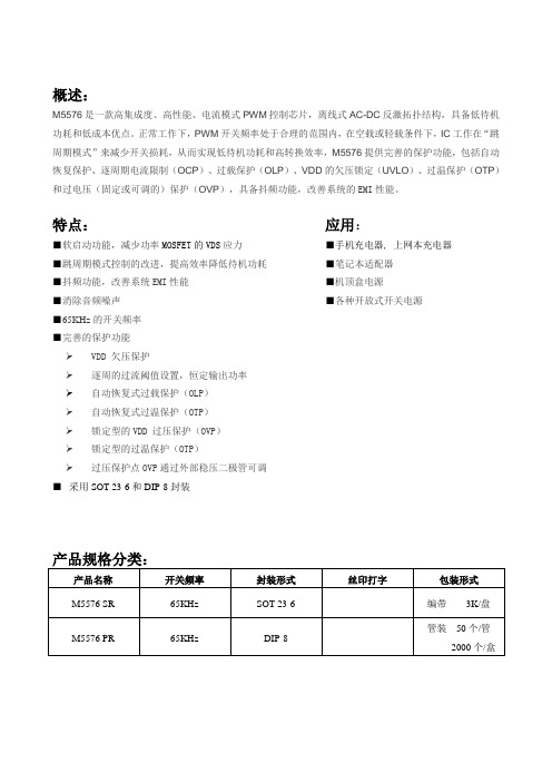
概述:M5576是一款高集成度、高性能、电流模式PWM控制芯片,离线式AC-DC反激拓扑结构,具备低待机功耗和低成本优点。
正常工作下,PWM开关频率处于合理的范围内,在空载或轻载条件下,IC工作在“跳周期模式”来减少开关损耗,从而实现低待机功耗和高转换效率,M5576提供完善的保护功能,包括自动恢复保护、逐周期电流限制(OCP)、过载保护(OLP)、VDD的欠压锁定(UVLO)、过温保护(OTP)和过电压(固定或可调的)保护(OVP),具备抖频功能,改善系统的EMI性能。
特点:应用:■软启动功能,减少功率MOSFET的VDS应力■手机充电器, 上网本充电器■跳周期模式控制的改进,提高效率降低待机功耗■笔记本适配器■抖频功能,改善系统EMI性能■机顶盒电源■消除音频噪声■各种开放式开关电源■65KHz的开关频率■完善的保护功能VDD 欠压保护逐周的过流阈值设置,恒定输出功率自动恢复式过载保护(OLP)自动恢复式过温保护(OTP)锁定型的VDD 过压保护(OVP)锁定型的过温保护(OTP)过压保护点OVP通过外部稳压二极管可调■采用SOT-23-6和DIP-8封装典型应用:图1 M5576SR 应用图SOT-23-6图2 M5576PR 应用图DIP-8管脚排列图:M5576PR M5576SR 图3 DIP-8(顶部视图) 图4 SOT-23-6(顶部视图)管脚描述:芯片使用时极限参数:注:如果器件工作条件超出上述各项极限值,可能对器件造成永久性损坏。
上述参数是工作条件的极限值,不建议器件工作在推荐条件以外的情况。
器件长时间工作在极限工作条件下,其可靠性及寿命可能受到影响。
芯片内部框图:图5 M5576内部框图电气参数(Ta=25o C):应用信息M5576是一款高集成度、高性能、电流模式PWM控制芯片,离线式AC-DC反激拓扑结构,具备低待机功耗和低成本优点。
扩展模式大大降低了待机功耗,方案设计适应国际节能的要求。

16位A D转换器M A X1166的原理及应用16位A/D转换器MAX1166的原理及应用摘要:MAX1166是美国MAXIM公司生产的逐次逼近型16位低功耗模数转换器,该转换器内带4.096V精密参考源,同时具有并行数据输出接口。
文章介绍了该模数转换器的特性、功能及实际应用电路。
关键词:A/D转换单片机接口 MAX1166 1概述MAX1166是美国MAXIM公司生产的逐次逼近型16位模数转换器,该芯片片内除集成了逐次逼近型ADC所必须的逐次逼近寄存器SAR、高精度比较器和控制逻辑外,还集成了时钟、4.096V精密参考源和接口电路,其内部结构框图如图1所示。
MAX1166的数据总线为8位,因此与目前广泛使用的8位微处理器连接非常方便。
MAX1166的典型参数如下:●并行数据输出接口:8位●采样频率:165ksps●精度:最大线性误差%26;#177;2LSB,16位无误码●内部参考源电压:4.096V●外部参考源电压输入范围:+3.8~5.25V●模拟电压输入范围:+4.75~+5.25V●数字电压输入范围:+2.7~+5.25V●小电流外部参考电源流为1.8mA内部参考电源流为2.7mA采样率在10ksps时的外部参考电源电流为0.1μA;●采用20管脚TSSOP封装。
MAX1166共有20个引脚,图2为其引脚排列图,这些引脚大体可分为三类。
第一类是电源类其中,模拟电源AVDD和数字电源DVDD应分别通过0.1μF的钽电容与模拟地和数字地相连接。
而数字地DGND和模拟地AGND1、AGND2通常共地。
第二类为模数信号类其中,AIN为模拟信号输入端;D0/D8~D7/D15为数字量并行输出口。
第三类是控制信号类其中CS输入为转换启动端;R/C(输入)为读取结果/模数转换控制端;EOC(输出)用于指示转换结束;HBEN输入用来控制从总线读出的数据是转换结果的高字节还是低字节;REFADJ为参考电源选择端,该端通过0.1μF钽电容与模拟地相接时选择内部参考电源模式而当其直接与模拟电源相接时选择外部参考电源模式;REF为参考电源输入/输出端,选择内部参考电源时该脚应通过4.7μF钽电容接模拟地而选择外部参考电源时该脚为外部参考电源输入端。

THIN QFN17181920212223GNDDL2V+LDOOUT DL1LDOON BST18765432REFILIM2ILIM1VCC TONLSAT SKIP MAX15401OVP/UVP 24LX1THIN QFN23242526272829V+LDOIN V DD LDOOUT FBLDO DL1LDOON 8765432ILIM1CC1GATE V CC TON LSAT SKIP MAX15411OVP/UVP 30BST12122GNDDL2109REFILIM2*V+TON SKIPILIM1CSP1CSN1BST1DH1LX1*V DD DL1**CC1GND LSA TILIM2CSP2CSN2BST2DH2LX2*V DD V CCDL2GND REF13R0.7V7RMAX1540/MAX1541FB1**REFIN1OUT1ON1PGOOD1FB2OUT2ON2PGOOD2FAULT1INT REF1INT FB1INT FB2FAULT2**FBLANK**ODOVP/UVPBLANKENABLE OVPENABLE UVP *LDOIN*LDOOUT **FBLDO LDOON**GA TEMAX1540/MAX1541INT REF2MAX1540、MAX1541是笔记本电脑中常用的内存/芯片组供电控制芯片。
MAX1540、MAX15MAX1540、MAX1541的内部电路框图MAX1540、MAX1541的针脚封装图限流电路1PWM控制器限流电路2PWM控制器输入电压FB1 译码器FB2 译码器2.0V基准空载译码空载译码/计时器低压差稳压器饱和限制过零比较限流MAX1541才有该部分电路POWER GOOD信号产生电路与错误信号保护电路POWER GOOD信号产生电路与错误信号保护电路饱和限制过零比较限流引脚号引脚名称引脚功能MAX1540MAX154111OVP/UVP过压/欠压保护和放电模式控制输出端。
ads1115原理(一)ads1115的相关原理解析什么是ads1115•ads1115是一种高精度、低功耗的模拟转换器(ADC)•它由德州仪器(Texas Instruments)公司推出,是一款采用I²C 接口的16位ADC芯片I²C接口简介•I²C全称为Inter-Integrated Circuit,是一种串行通信协议•ads1115利用I²C接口与主控设备进行通信•I²C接口具有双线制,包括串行数据线(SDA)和串行时钟线(SCL)ads1115的工作原理1.ads1115通过SDA和SCL接收来自主控设备的指令和时钟信号2.主控设备发送启动信号,ads1115进入工作模式3.ads1115根据指令进行模拟输入信号的采样和转换4.转换完成后,ads1115将结果存储在16位寄存器中5.主控设备通过读取寄存器中的数据获取转换结果ads1115的特点•高精度:ads1115的分辨率达到16位,提供更准确的模拟信号转换•低功耗:ads1115的设计旨在降低能耗,适用于电池供电的应用•内置比较器:ads1115可以通过内置的比较器实现电压或电流的阈值检测•多路输入:ads1115提供4个单端或2个差分输入通道,满足不同应用的需求ads1115的应用场景•电池管理:利用ads1115的低功耗和高精度特点,进行电池电压监测和容量估算•温度测量:通过连接温度传感器,利用ads1115进行精确的温度测量•压力监测:结合压力传感器,ads1115可以测量液体或气体中的压力,并输出相应的模拟信号总结•ads1115是一款高精度、低功耗的模拟转换器•它利用I²C接口与主控设备进行通信,完成模拟输入信号的采样和转换•ads1115具有高精度、低功耗、多路输入等特点,适用于多种应用场景以上就是对ads1115的相关原理的解析,希望对读者有所帮助。
ads1115的寄存器解析前言•ads1115具有多个寄存器,用于存储配置信息和转换结果•理解寄存器的作用和配置将有助于使用ads1115进行准确的模拟信号转换寄存器列表1.寄存器0:配置寄存器(Config Register)2.寄存器1:控制寄存器(Control Register)3.寄存器2:低字节数据寄存器(Low Byte Data register)4.寄存器3:高字节数据寄存器(High Byte Data register)配置寄存器详解•配置寄存器用于设置ads1115的工作模式和参数•共有16个位,每个位对应一个特定的功能或配置选项工作模式•Bit 15:MODE(模式位)–0:连续转换模式–1:单次转换模式输入选择•Bit 14-12:MUX(输入选择位)–000:AINP = AIN0,AINN = AIN1(差分输入0-1)–001:AINP = AIN0,AINN = AIN3(差分输入0-3)–010:AINP = AIN1,AINN = AIN3(差分输入1-3)–011:AINP = AIN2,AINN = AIN3(差分输入2-3)–100:AINP = AIN0,AINN = GND(单端输入AIN0)–101:AINP = AIN1,AINN = GND(单端输入AIN1)–110:AINP = AIN2,AINN = GND(单端输入AIN2)–111:AINP = AIN3,AINN = GND(单端输入AIN3)增益选择•Bit 11-9:PGA(增益选择位)–000:FSR = ±6.144V–001:FSR = ±4.096V–010:FSR = ±2.048V–011:FSR = ±1.024V–100:FSR = ±0.512V–101:FSR = ±0.256V–110:FSR = ±0.256V–111:FSR = ±0.256V 数据速率•Bit 8-5:DR(数据速率位)–0000:8 SPS–0001:16 SPS–0010:32 SPS–0011:64 SPS–0100:128 SPS–0101:250 SPS–0110:475 SPS–0111:860 SPS–1000:8 SPS–1001:16 SPS–1010:32 SPS–1011:64 SPS–1100:128 SPS–1101:250 SPS–1110:475 SPS–1111:860 SPS操作模式•Bit 4:OS(操作模式位)–0:尚未启动转换–1:启动转换操作状态•Bit 3:OS-单次位–0:未完成单次转换–1:完成单次转换引脚禁用•Bit 2:COMP_MODE(比较器模式位)–0:比较器模式功能启用–1:比较器模式功能禁用比较器开关•Bit 1:COMP_POL(比较器极性位)–0:比较器输出为标准–1:比较器输出翻转比较器模式•Bit 0:COMP_LAT(比较器延迟位)–0:比较器延迟功能启用–1:比较器延迟功能禁用以上就是ads1115的寄存器配置解析,希望能帮助你更好地理解ads1115的工作原理和设置。
第30卷 第3期 苏州科技大学学报(工程技术版)V ol. 30 No. 3 2017 年 9 月Journal of Suzhou University of Science and Technology(Engineering and Technology)Sep.2017基于ADS1115多通道低功耗环境参数检测系统设计李长才肖金球4华猛^(1.苏州科技大学电子与信息工程学院,江苏苏州215009;2.苏州市智能测控工程技术研究中心,江苏苏州215009)摘要:为了可靠准确地检测环境参数,尽可能降低功耗,设计了基于ADS1115多通道低功耗检测系统。
采用 ADS1115作为数据采样与转化模块,STM32处理器作为控制与处理模块。
通过配置ADS1115寄存器,进行通道转换 与数据采集。
利用STM32的待机模式,大大降低了系统功耗。
给出了 ADS1115芯片的简介、硬件设计方案、软件实现 方法以及最终测试结果。
经测试,该检测系统具有功耗低、体积小、可靠稳定以及功能扩展性好等特点,适用于对功 耗要求比较高的数据采集与测量环境中。
关键词:ADS1115;参数检测;多通道;STM32;低功耗中图分类号:TP274 文献标识码:A文章编号:2096-3270(2017)03-0077-04当前,模数、数模转化器[1]已经被广泛的应用在工业、通信、汽车及消费类领域,在电子智能测量技术的 高速发展的趋势下,对数据采集与转换的要求也越来越高。
特别是在电能供应不便的地方,数据采集需要的 电能只有通过电池或太阳能板提供,所以需要模数转换器具有低功耗特性。
此外,数据采集检测系统还需要 稳定、可靠、安全地运行,实现对数据的测量与监控。
ADS1115不仅具有低功耗的特性,而且体积小、精度高,集成了多路复用器以及増益放大器等部件,简化了外围电路的设计。
在特定的场合,能够充分发挥其优势。
该文设计了基于ADS1115多通道低功耗环境参数检测系统I利用ADS1115单次转化模式以及STM32处 理器的待机模式,大大降低了整个系统的功耗,实现了系统可靠稳定运行。