实时时钟及温度传感器芯片DS1629的接口与应用
- 格式:pdf
- 大小:635.02 KB
- 文档页数:4

智能温控风扇设计摘要:本文综述了温度控制技术的有关概念以及现今温度控制技术存在的问题,同时介绍了温度控制技术的发展历史以及研究现状并指出随着温度控制技术的不断发展,温度控制技术将朝着高精度、智能化等方面快速发展关键词:温度控制;发展;智能化The design of Intelligent Temperature Control Fan Abstract:This paper discusses conceptions related to temperature control and points out the main problem of temperature control technology. And it also states development background and furture development of intelligent temperature control system and it points out that with these development of temperature control technology, the temperature control system will become more precise, intelligent.Key words: temperature control; development;intelligent1.1 综述目的随着温度控制技术与计算机、通信等技术的不断结合,使得现今的温度控制技术在过去几十年里有了极大发展。
同时,随着工业化生产的不断发展,其对温度控制的提出了高精度、高智能化的发展要求。
因此,介绍了解当前温度控制系统的发展状况对设计研究高精度、高智能化的温度控制系统有其积极意义。
1.2 有关概念PID控制——将偏差的比例、积分、微分通过线性组合构成控制量。
用这一控制量对被控对象进行控制,这样的控制称为PID控制。
![[课件]智能传感器PPT](https://uimg.taocdn.com/be9fa7f628ea81c758f5783b.webp)
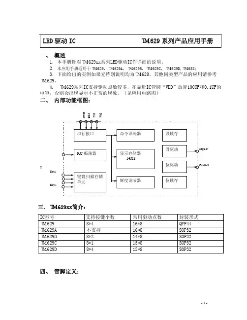
江苏省无锡市蠡园经济开发区滴翠路100号9栋2层 第 1 页 共 13 页http://www.i-core. cn 邮编:214072 版本:2011-12-A1AIP1629ALED驱动控制专用电路产品说明书说明书发行履历:版本 发行时间 新制/修订内容2011-12-A1 2011-12新制深圳富瑞世嘉 中微爱芯一级代理手机(微信):13530167943网 址:www.forchip.cn1、概 述AIP1629A 是一块LED 驱动专用电路,内置MCU 数字接口、数据锁存器等电路。
主要应用于冰箱、空调 、家庭影院等产品显示屏的驱动控制。
其主要特点如下: ● 采用功率CMOS 工艺 ● 显示模式:16段×8位● 辉度调节电路(占空比8级可调) ● 串行接口(CLK 、DIO 、STB ) ● 内置RC 振荡(400KHz±5%)● 内置上电复位电路 ● 封装形式:SOP322、功能框图及引脚说明2.1、引脚排列图图1、引脚排列图江苏省无锡市蠡园经济开发区滴翠路100号9栋2层 第 2 页 共 13 页http://www.i-core. cn 邮编:214072 版本:2011-12-A1深圳富瑞世嘉 中微爱芯一级代理手机(微信):13530167943网 址:www.forchip.cn2.3、引脚说明引脚 符 号引脚名称功 能1、2、4、5、28、29、31、32GRID1~GRID8 输出(位)位输出, N 管开漏输出。
7 DIO 数据输入 在时钟上升沿输入串行数据, 从低位开始。
8 CLK时钟输入 在时钟上升沿输入串行数据9 STB 片选 在上升或下降沿初始化串行接口, 随后等待接收指令。
STB 为低后的第一个字节作为指令,当处理指令时,当前其它处理被终止。
当STB 为高时,CLK 被忽略。
3、6、30 VSS逻辑地接系统地 10、27VDD逻辑电源5V±10%11~26 SEG1~SEG16输出(段)段输出, P 管开漏输出。
AiP1629A3-line Serial Interface/Common Cathode16Seg*8GridLED Controller/DriverProduct Specification1、General DescriptionAiP1629A is an LED Controller driven on a 1/8 duty factor.16segment output lines,8 grid output lines, one display memory, control circuit are all incorporated into a single chip to build a highly reliable peripheral device for a single chip microcomputer. Serial data is fed to AiP1629A via a three-line serial interface. Housed in a 32 pins SOP package, AiP1629A pin assignments and application circuit are optimized for easy PCB Layout and cost saving advantages.Features:CMOS technologydisplay modes(16 segment*8 grid)8-step dimming circuitrySerial interface for clock, data input, strobe pinsBuilt-in RC oscillator: (400KHz±5%)Available in 32 pins, SOP2、Block Diagram And Pin Description2.1、Pin Configurations2.2、Pin DescriptionPin No. Pin NameDescription 1、2、4、5、28、GRID1~Grid Output Pins29、31、32 GRID87 DIO8 CLKData input PinThis pin inputs serial data at the rising edge of the shift clock(starting from the lower bit)Clock input Pin .This pin reads serial data at the rising edge andoutputs data at the falling edge.9 STBSerial Interface Strobe PinThe data input after the STB has fallen is processed as acommand. When this pin is “HIGH”, CLK is ignored.3、6、30 VSS Ground Pin10、27 VDD Power Supply11~26 SEG1~SEG16 Segment Output Pins3、Electrical Parameter3.1、Absolute Maximum Ratings(Tamb=25℃, All voltage referenced to Vss, unless otherwise specified)Characteristic Symbol Conditions Value Unit Supply Voltage VDD -0.5~7.0 V Input Voltage V I -0.5~VDD+0.5 VDrive output current I O1 -50 mAI O2 +200 mA Power Dissipation P D 400 mW Operating Temperature T amb -40~+80 ℃torage Temperature T stg -65~+150 ℃Soldering Temperature T L 10s 250 ℃3.2、Recommended Operating Range(Ta= -20℃~+70℃,GND=0V)Parameter Symbol Min. Typ. Max. Unit Logic supply voltage V DD 3 5 5.5 VHigh-level input voltage V IH 0.7V DD - V DD VLow-level input voltage V IL 0 - 0.3V DD V3.3、Electrical Characteristics3.3.1 DC Characteristics (Tamb=25 C , VDD=4.5~5.5V, unless otherwise specified)Parameter Symbol Conditions Min. Typ. Max. Unit High-level output I OH1 SEG1~SEG16,V o=VDD -2V -20 -25 -40 mA current I OH2 SEG1~SEG16,V o= VDD-3V -20 -30 -50 mA3/ 13Low-level outputcurrent I OL1 GRID1~GRID8,Vo=0.3V 80 140 -mALow-level output current Segment Idout VO = 0.4V,dout 4 --mAHigh-level output Itolsg VO = VDD–3V,SEG1~SEG16 -- 5 % current toleranceInput leakagecurrent II VI=VDD/VSS --±1 µA High-level inputvoltage V IH CLK,DIO, STB 0.7VDD --V Low-level inputvoltage V IL CLK,DIO, STB --0.3VDD V Hysteresis Voltage V H CLK,DIO, STB -0.35 -V Dynamic currentdissipation IDDdyn No load , display off -- 5 mA3.3.2 AC Characteristics (Tamb=25 C , VDD=4.5~5.5V, unless otherwise specified)Parameter Symbol Conditions Min Typ Max Unit Oscillationf OSC - 400 - KHz frequencyPropagation t PLZ CLK→DIO - - 300 ns delay t PZL CL=15pF, R L=10KΩ- - 100 nsSeg1/KS1~T TZH1 - - 2 us Rise Time CL=300pF Seg8/KS8T TZH2Grid1~Grid8 - - 0.5usFall Time T THZ CL=300pF、Segn、Gridn - - 120us Maximum clockFmax Duty=50% 1 - - MHz frequencyInputC I - - - 15 pF capacitance3.3.3 Timing Characteristics(Ta= -20℃~+70℃,V DD=4.5V~5.5V)Parameter Symbol Conditions Min Typ Max Unit C lock pulse width PWCLK - 400 - - ns STB pulse width PWSTB - 1 - - μs S et-up time for data t SETUP - 100 - - ns H old time for data t HOLD - 100 - - ns Propagation delayt CLK STB CLK↑→STB↑ 1 - - μs CLK to STBWait time t WAIT CLK↑→CLK↓ 1 - - μs4、Function Description4.1、Display mode AND RAM addressData transmitted from an external device to AiP1629A via the serial interface are stored in the Display RAM and are assigned addresses. The RAM addresses of AiP1629A are given below in 8 bits unit.xxHL(low 4 bit) xxHU(high 4 bit) xxHL(low 4 bit) xxHU(high 4 bit)B0 B1 B2 B3 B4 B5 B6 B7 B0 B1 B2 B3 B4 B5 B6 B7 00HL 00HU 01HL 01HU GR102HL 02HU 03HL 03HU GR204HL 04HU 05HL 05HU GR306HL 06HU 07HL 07HU GR408HL 08HU 09HL 09HU GR50AHL 0AHU 0BHL 0BHU GR60CHL 0CHU 0DHL 0DHU GR70EHL 0EHU 0FHL 0FHU GR8 NOTE:when power up, first transfer data to RAM, and then setup display on.4.2、Commands DescriptionA command is the first byte (b0 to b7) inputted to AiP1629A via the DIO Pin after STB Pin has changed from HIGH to LOW State. Bit 7、bit 6 used to distinguish different instruction.B7 B6 Commands0 1 Data setting commands1 0 Display control commands1 1 Address setting commandsWhen input command, the STB can be set “1”,serial communication initialization, input command are invalid instruction.4.2.1、Data setting commandsThe Data Setting Commands executes the Data Write or Data Read Modes for AiP1629A,B1,B0can not set 01 or 11 or 10.B7 B6 B5 B4 B3 B2 B1 B0 Function Description0 1 XX 0 0 SET write write0 1 0 Auto increaseAddress increase0 1 1 Fixed address0 1 0 Normal modeTEST mode0 1 1 Test mode4.2.2、ADDRESS SETTING COMMANDSAddress Setting Commands are used to set the address of the display memory. The address is considered valid if it has a value of 00H to 0FH. If the address is set to 0FH or higher, the data is ignored until a valid4.3、Serial Communication FormatReceive 1 bit data all in rising of the clockWrite data time:4.4、DisplayCommon-cathode LED driverYou can write data”3F”in“00”address to set the digital tube display “0”Common-anode LED driverYou can write data ”01” in “00,02,04,06,08,0a” address and other address write “00” to set the digital tube display “0”.SEG8 SEG7 SEG6 SEG5 SEG4 SEG3 SEG2 SEG10 0 0 0 0 0 0 1 00H0 0 0 0 0 0 0 1 02H0 0 0 0 0 0 0 1 04H0 0 0 0 0 0 0 1 06H0 0 0 0 0 0 0 1 08H0 0 0 0 0 0 0 1 0AH0 0 0 0 0 0 0 0 0CHB7 B6 B5 B4 B3 B2 B1 B0Note: SEGn p-channel, open drain output, GRIDn N-channel, open drain output. when using, SEGn connect to anode of LED, GRIDn connect to cathode of LED.4.5、The serial data transfer in the applications4.5.1、Address Increasing ModeDisplay memory is updated by incrementing addresses. Please refer to the following diagram.where:Command 1: Data setting commandCommand 2: Address settingcommandData 1 to n: Transfer display data (16bytes max.)Command 3: Display control command4.5.2、Fixing AddressThe following diagram shows the waveforms when updating specific addresses.where:Command 1:Data setting commandCommand 2:Address setting commandData 1 : display dataCommand 3:Address settingcommand Data 2 : display data。
DS18B20数字温度计设计西南大学工程技术学院,重庆 400716摘要:本文介绍了利用美国DALLAS半导体公司最新推出的一种改进型智能温度传感DS18B20和ATMEL公司生产的AT89C2051,结合四位共阳型LED,采用动态显示的方法实现室内温度的检测和读数。
本文设计的数字温度计基于DS18B20单线总线结构,与单片机的接口电路简单无须外部电路,同时由于DS18B20能直接读出被测温度,并且可根据实际要求通过简单的编程实现9~12位的数字值读数方式,因而使得整体设计思路简单,可以实现-55~+125゜C的温度测量,精度误差在0.1゜C以内。
本文给出了具体的硬件电路和软件设计。
关键词:单片机DS18B20智能温度传感器DS18B20 DIGITAL THERMOMETER DESIGNLI XuejianCollege of Engineering and Technology, Southwest University, Chongqing 400716, ChinaAbstract:This paper presents the method for a digital thermometer design made of DS18B20,a newly-product of advaced Programmable Resolution 1-Wire® Digital Thermometer(DALLAS),and AT89C2051 (ATMEL).This design adopts dynamic dispay method with four LED to measu re room temperature.This digital thermometer is based on the one wire configuration of DS18B 20, and no external circuit is required.Since the measured temperature can be directly read by DS18B20 and 9-12 digits reading can be implemented through simple programming, the overall design concept is simple. Temperature within -55~+125゜C can be measured with an error of +/-0.1゜C. Detailed circuits and softwaredesign are given here.Key Words:single-chip computer DS18B20 smart temperature sensor文献综述自动控制领域中,温度检测与控制占有很重要地位。
FM38025T 实时时钟芯片产品说明书2017. 07本资料是为了让用户根据用途选择合适的上海复旦微电子集团股份有限公司(以下简称复旦微电子)的产品而提供的参考资料,不转让属于复旦微电子或者第三者所有的知识产权以及其他权利的许可。
在使用本资料所记载的信息最终做出有关信息和产品是否适用的判断前,请您务必将所有信息作为一个整体系统来进行评价。
采购方对于选择与使用本文描述的复旦微电子的产品和服务全权负责,复旦微电子不承担采购方选择与使用本文描述的产品和服务的责任。
除非以书面形式明确地认可,复旦微电子的产品不推荐、不授权、不担保用于包括军事、航空、航天、救生及生命维持系统在内的,由于失效或故障可能导致人身伤亡、严重的财产或环境损失的产品或系统中。
未经复旦微电子的许可,不得翻印或者复制全部或部分本资料的内容。
今后日常的产品更新会在适当的时候发布,恕不另行通知。
在购买本资料所记载的产品时,请预先向复旦微电子在当地的销售办事处确认最新信息,并请您通过各种方式关注复旦微电子公布的信息,包括复旦微电子的网站(/)。
如果您需要了解有关本资料所记载的信息或产品的详情,请与上海复旦微电子集团股份有限公司在当地的销售办事处联系。
商标上海复旦微电子集团股份有限公司的公司名称、徽标以及“复旦”徽标均为上海复旦微电子集团股份有限公司及其分公司在中国的商标或注册商标。
上海复旦微电子集团股份有限公司在中国发布,版权所有。
目录目录 (3)1说明 (4)2产品综述 (5)2.1产品简介 (5)2.2产品特点 (5)2.3性能指标 (5)2.3.1极限参数 (5)2.3.2电参数 (6)2.4引脚说明 (7)2.4.1SOP14封装 (7)2.4.2引脚功能定义 (7)3封装信息 (8)3.1SOP14封装 (8)版本信息 (9)上海复旦微电子集团股份有限公司销售及服务网点 (10)1 说明本文档为FM38025T芯片简单技术手册。
FM38025T是复旦微电子公司开发的低功耗RTC芯片,请联系复旦微电子公司提供更多相关文档支持设计开发。
温湿度智能测控系统摘要本设计实现的是单片机温湿度测量与控制系统,通过在LCD1602 上实时显示室内环境的温度和相对湿度。
系统采用集温湿度传感器与A/D 转换器为一体的DHT90 传感器芯片,通过单片机AT89C52 处理进行显示,其它模块包括了实时时钟/日期产生电路和超限报警处理电路,对所测量的值进行实时显示和报警处理。
本文介绍了基于ATMEL 公司的AT89C52 系列单片机的温湿度实时测量与控制系统和显示系统的设计,包括介绍了硬件结构原理,并分析了相应的软件的设计及其要点,包括软件设计流程及其程序实现。
系统结构简单、实用,提高了测量精度和效率。
关键词:温湿度测控DHT90 传感器AT89C52 单片机LCD1602AbstractThe design and implementation of measurement and control temperature and humidity is MCU system, through which the temperature and humidity measurement LCD1602. System adopts set temperature and humidity sensor and A/D converter for DHT90 chip microcontroller processing, through that other modules including real-time clock/date produce circuit and the off-gauge alarm circuit, the value of measurement for real-time display and alarm.The paper introduces the ATMEL company based on AT89C52 single-chip series of temperature and humidity measurement and control system and real-time display system design, including the hardware structure and principle, and the corresponding software design, including the design of the software and its key process and procedure.System structure is simple,practical, and improve the measuring precision and efficiency.Keywords:temperature and humidity control, DHT90, LCD1602,AT89C52目录摘要 (I)Abstract (II)目录 (III)前言 (1)1 概述 (2)1.1 温度、湿度数据采集与监测技术的发展历程 (2)1.2 内外温度和湿度测量的发展史 (3)2 系统总体设计 (6)2.1 系统功能设计 (6)2.2 系统设计原则 (6)3 方案论证与比较 (8)3.1 3.2 3.3 3.4数据采集部分 (8)控制部分 (9)显示部分 (10)系统框架图 (10)4 系统硬件结构 (11)4.1 温湿度传感器DHT90 (13)4.1.1 温湿传感器DHT90 的简介 (13)4.1.2 接口说明 (14)4.1.3 温湿传感器DHT90 的工作过程 (14)4.1.4 输出转换为物理量 (16)4.2 AT89C52 (18)4.2.1 主要性能参数 (18)4.2.2 功能特性概述 (18)4.2.3 特殊功能寄存器 (21)4.2.4 存储器结构 (23)4.2.5 看门狗定时器 (24)4.2.6 定时器2 (25)4.2.7 中断 (27)4.3 单片机最小系统的设计 (27)4.3.1 复位电路设计 (27)4.3.2 时钟电路设计 (28)4.3.3 报警电路 (28)4.3.4 键盘设定模块 (29)4.3.5 稳压电路 (30)4.4 软件设计 (30)5系统软件设计 (31)6仿真与调试 (32)6.1 仿真 (32)6.2 硬件调试 (33)总结 (35)致谢 (37)参考文献 (38)附件 (39)前言在现代工业现场,随着科技的进步和自动化水平的提高,电缆的用量越来越大,电缆的安全保护已成为不可忽视的问题。
使⽤TM1629A芯⽚驱动⽶字数码管⽶字数码管可以显⽰数字和26个英⽂字母,应⽤范围⽐8字数码管更⼴泛⼀些。
市⾯上常见的⽶字数码管有三种,⼀种是15段的,另⼀种是16段,还有⼀种是17段的。
TM1629A可以驱动15和16段的数码管。
⼀、TM1629A主要参数共阴数码管:16 段 × 8 位共阳数码管:8 段 × 16 位8级辉度调节串⾏接⼝(CLK,STB,DIO)逻辑电源电压范围:-0.5~7.0V正常⼯作电压电压:5.0V ⼿册在天微官⽹上有,百度⼀下也很多。
⼆、电路设计 ⼿册给出了两个驱动8位数码管的电路,并未给出驱动⽶字数码管的电路。
参照这两个电路设计了驱动15位红⾊⽶字管的电路。
经过试验,电源电压完全可以使⽤3.3V,亮度⾮常⾼,甚⾄曾烧坏过⼀个笔画,也不知是不是数码管的质量问题。
三、驱动程序 该芯⽚有3个控制线,分别是:DIO:数据输⼊线CLK:时钟输⼊线STB:⽚选线 需要注意的是,TM1629A的CLK的时钟周期较慢(⼤于500ns),要根据MCU的频率测试⼀下,如果不能满⾜要求,要加⼊适当的延时。
特别需要注意的是时序图中的t CLK-STB和PW STB,都要求最⼩1us。
最好的办法是在DIO、CLK、STB变化的前后都插⼊⾜够长时间的延时,整个调通后再优化时间。
3.1 初始化⼯作 ⾸先进⾏初始化⼯作,主要是定义功能脚的⼯作模式。
1/****************************************************2*说明:初始化TM1629A3*备注:io.h中定义了 STB P3^2,CLK P3^3,DIO P5^54****************************************************/5void TM1629A_Init(void)6 {7/*GPIO初始化,均为开漏输出*/8 SET_BIT(P3M1, 2); //宏功能:令P3M1的BIT2=19 SET_BIT(P3M0, 2);10 SET_BIT(P3M1, 3);11 SET_BIT(P3M0, 3);12 SET_BIT(P5M1, 5);13 SET_BIT(P5M0, 5);14/*STB、CLK赋初值*/15 STB = 1;16 CLK = 1;17 }3.2 基本的写⼊函数 实际⼯作频率设定的是5.5296MHz。
2007 Microchip Technology Inc.超前信息DS70265A_CNdsPIC33FJ12MC201/202数据手册高性能16位数字信号控制器查询DSPIC33FJ12MC202|DSPIC33FJ12MC201供应商捷多邦,专业PCB打样工厂,24小时加急出货DS70265A_CN 第ii 页超前信息2007 Microchip Technology Inc.提供本文档的中文版本仅为了便于理解。
请勿忽视文档中包含的英文部分,因为其中提供了有关Microchip 产品性能和使用情况的有用信息。
Microchip Technology Inc.及其分公司和相关公司、各级主管与员工及事务代理机构对译文中可能存在的任何差错不承担任何责任。
建议参考Microchip Technology Inc.的英文原版文档。
本出版物中所述的器件应用信息及其他类似内容仅为您提供便利,它们可能由更新之信息所替代。
确保应用符合技术规范,是您自身应负的责任。
Microchip 对这些信息不作任何明示或暗示、书面或口头、法定或其他形式的声明或担保,包括但不限于针对其使用情况、质量、性能、适销性或特定用途的适用性的声明或担保。
Microchip 对因这些信息及使用这些信息而引起的后果不承担任何责任。
如果将Microchip 器件用于生命维持和/或生命安全应用,一切风险由买方自负。
买方同意在由此引发任何一切伤害、索赔、诉讼或费用时,会维护和保障Microchip 免于承担法律责任,并加以赔偿。
在Microchip 知识产权保护下,不得暗中或以其他方式转让任何许可证。
商标Microchip 的名称和徽标组合、Microchip 徽标、Accuron 、dsPIC 、K EE L OQ 、K EE L OQ 徽标、microID 、MPLAB 、PIC 、PICmicro 、PICSTART 、PRO MATE 、rfPIC 和SmartShunt 均为Microchip Technology Inc.在美国和其他国家或地区的注册商标。
E:\Item\design\tmxx led demo\sw\currency.c/***************************************************************************************************File name: Author: Version: Date: MCU:leddriver demo programmexcwyleddemo 0.12006年7月21日AT89S5212Mkeilc v3.05c// 文件名// 作者// 版本// 完成日期// 单片机型号// 单片机使用的晶体频率// 软件开发环境Description: 本程序是深圳市天微电子有限公司LED驱动IC的演示程序,采用C语言编写// 用于详细说明此程序文件完成的主要功能,与其他模块// 或函数的接口,输出值、取值范围、含义及参数间的控// 制、顺序、独立或依赖等关系Others: 本程序仅仅提供演示,任何个人或企业直接使用本程序造成的损失本公司不承担任何责任// 其它内容的说明Function List: 1.delay()2.indate()3.outdate()4.display()——延时程序——通过MCU向LEDdriver中写入一字节的数据——通过MCU从LEDdriver中读出一字节的数据——采用地址自动加1方式的显示程序5.display2()——采用固定地址方式的显示程序6.in_led()7.out_sw() ——采用地址自动加一方式先LED显存——读SW输入口状态// 主要函数列表,每条记录应包括函数名及功能简要说明History:1. Date:Author:// 修改历史记录列表,每条修改记录应包括修改日期、修改// 作者及修改内容简述2006年7月21日9:02xcwyModification:1)进一步添加了详细的注释2. Date:Author: xcwy2006年12月17日Modification:1)修改为本公司通用的LED驱动程序*************************************************************************************************** */ #include <REG52.h>#include<stdio.h>#include<intrins.h>//**************************************************************************************************#define #define #define #define #define #define #define #define #define #define #define #define #define #define #define #define #define #define #define #define tm1616tm1618tm1618atm1620tm1620btm1623tm1624tm1626atm1626btm1626ctm1626dtm1628tm1629tm1629atm1629btm1629ctm1629dtm1638tm1668tw16281234567891011121314151617181920#define icmodel tm1616 //这里选择的TM1616,更改“tm1616”可以得到其他型号IC的驱动程序#if icmodel==tm1616E:\Item\design\tmxx led demo\sw\currency.c#define seg #define grid 7 4#define dismodel 1#elif icmodel==tm1618#define seg #define grid #define key 5 7 3#define dismodel 4#elif icmodel==tm1618a#define seg #define grid #define key 7 5 4#define dismodel 2#elif icmodel==tm1620#define #define seggrid86#define dismodel 3 #elif icmodel==tm1620b#define #define #define seggridkey673#define dismodel 4 #elif icmodel==tm1623#define #define #define seggridkey1174#define dismodel 4 #elif icmodel==tm1624#define #define seggrid117#define dismodel 4 #elif icmodel==tm1626a#define #define #define #define #define seggridkeyswled107526#define dismodel 4 #elif icmodel==tm1626b#define #define #define #define #define seggridkeyswled117546#define dismodel 4 #elif icmodel==tm1626c#define #define #define #define seggridkeyled11751#define dismodel 4 #elif icmodel==tm1626d#define #define #define #define seggridkeyled10751#define dismodel 4 #elif icmodel==tm1628#define #define #define seggridkey1074#define dismodel 4 #elif icmodel==tm1629E:\Item\design\tmxx led demo\sw\currency.c#define #define #define seggridkey1684#define dismodel 1 #elif icmodel==tm1629a#define #define seggrid168#define dismodel 1 #elif icmodel==tm1629b#define #define #define seggridkey1484#define dismodel 1 #elif icmodel==tm1629c#define #define #define seggridkey1584#define dismodel 1 #elif icmodel==tm1629d#define #define #define seggridkey1284#define dismodel 1 #elif icmodel==tm1638#define #define #define seggridkey1084#define dismodel 1 #elif icmodel==tm1668#define #define #define seggridkey1075#define dismodel 1 #elif icmodel==tw1628#endif #else#error "你必须确认IC的型号是否存在?"#define#define#define#defineseggridkeydismodel10751#define #define #define #define #define #define #define #define #define #define dissetmodewritedatamode_zwriteledmode_zreadkeymodereadswmodewritedatamode_gwriteledmode_gstartaddressdisconmodedatacount0x030x400x410x420x430x440x450xc00x8c2*grid//显示模式设置//采用地址自动加一方式写显存//采用地址自动加一方式写LED显存命令//读按键命令//读SW口命令//采用固定地址方式写显存//采用固定地址方式写LED显存命令//起始地址//显示控制//采用地址自动加一方式传输数据的个数//定义全局变量unsigned char k1,k2,k3,k4,k5; unsigned da_sw; //按键值寄存器//SW寄存器unsigned int//端口的定义count;sbit sbit STBCLK=P2^0;=P2^1;sbit sbit DIOSPEAK=P2^2;=P2^7;//串行通讯口//外接蜂鸣器,可以不必理会//*********************************************子程序开始************************************E:\Item\design\tmxx led demo\sw\currency.c//----------------------------------------------延时程序开始---------------------------------void delay(int k){unsigned char i,j;for(;k>0;k--)for(j=255;j>0;j--)for(i=255;i>0;i--);}//----------------------------------------------延时程序结束----------------------------------//----------------------------------------------写入输入1个字节(8bit)到LED_IC程序开始--------- //输入8BIT数据//在时钟的上升沿通过MCU向LED驱动IC——TM16xx写数据void indate(unsigned char p){unsigned int i;STB=0; //保证“STB”为低电平,程序不依赖于之前端口的状态//保证程序在实际运行中不会出现“端口迷失”for(i=0;i<8;i++){CLK=0; //先将“CLK”清零if((p&0x01)!=0){}}else{}CLK=1;p=p>>1;DIO=1;DIO=0;//需要传送的数据的低位为“1”,则把“DIO”清零//需要传送的数据的低位为“0”,则把“DIO”置高//送时钟的上升沿//准备送下一个BIT//送完一个字节后退出循环}//----------------------------------------------写入输入1个字节(8bit)到LED_IC程序结束--------- //----------------------------------------------从LED_IC读入1个字节(8bit)程序开始------------- //输出8BIT数据//在时钟的上升沿通过MCU从LED驱动IC——TM16xx读数据#ifdef keyunsigned char outdate(){unsigned char i,k=0;DIO=1;STB=0; //i——控制循环次数,k——临时保存读到的数据//释放DIO为输入//保证“STB”为低电平,程序不依赖于之前端口的状态//保证程序在实际运行中不会出现“端口迷失”for(i=0;i<8;i++) {CLK=0;k=k>>1;if((P2&0x04)==0){k=k&0x7f;//先将“CLK”清零//如果“DIO”为低电平,则把k的最高位清“0”,其他各位保持不变}else{k=(k|0x80&0xff); //如果“DIO”为高电平,则把k的最高位置“1”,其他各位保持不变}CLK=1; }return(k);//送时钟的上升沿//送完一个字节后退出循环//返回读到的1字节数据}#endif//----------------------------------------------从LED_IC读入1个字节(8bit)程序结束----------- //----------------------------------------------采用地址自动加一方式传输地址和数据开始------ //采用地址自动加1方式E:\Item\design\tmxx led demo\sw\currency.c//上电后LED-DRIVER显存中的数据是随机的,上电后马上传显示控制命令字(打开显示),会出现乱码。
DS1621是DALLAS公司生产的一种功能较强的数字式温度传感器和恒温控制器。
与同系列的DS1620相比控制更为简单,接口与I2C总线兼容,且可以使用一片控制器控制多达8片的DS1621。
其数字温度输出达9位,精度为0.5℃。
通过读取内部的计数值和用于温度补偿的每摄氏度计数值,利用公式计算还可提高温度值的精度。
DS1621可工作在最低2.7V 电压下,适用于低功耗应用系统。
利用DS1621和一片2051单片机即可构成一个简洁但功能强大的低电压温度测量控制系统。
1. DS1621基本特性DS1621无需外围元件即可测量温度,将结果以9位数字量(两字节传输)给出,测量范围为-55℃~+155℃,精度为0.5℃;典型转换时间为1s;用户可自行设置恒温计的温度值,且将该设置值存储在非易失存储器中。
数据的读出和写入通过一个2-线串行接口完成,DS1621采用8脚DIP或SOIC封装。
2. 引脚描述及功能方框图DS1621的引脚描述如表1所列。
图1是DS1621的功能框图。
3. DS1621的工作方式DS1621既可独立工作(此时作为恒温控制器),也可通过2-线接口在MPU的控制下完成温度的测量和计算。
DS1621的工作方式是由片上的设置/状态寄存器来决定的,该寄存器的定义如下:其中DONE为转换完成位,温度转换结束时置1,正在进行转换时为0;THF为高温标志位,当温度超过TH预置值时置1;TLF为低温标志位,当温度低于TL预置值时置1;NVB为非易失存储器忙位,向片内E2PROM写入时置1,写入结束后复位写入E2PROM通常需要10ms;PCL为输出极性位,为1时激活状态为逻辑高电平,为0时激活状态为逻辑低电平,该位是非易失的;1SHOT为一次模式位,该位为1时每次收到开始转换命令执行一次温度转换,为0时执行连续温度转换,该位亦是非易失的。
DS1621在嵌入一个系统前,需由MPU将设置/状态寄存器值通过2-线接口写入该寄存器,之后DS1261或作为恒温计独立工作,或在MPU控制下进行温度测量和计算。
题目:电子温度计的设计专业:应用电子技术班级:电子3121作者:刘冬指导教师:程晓芳摘要随着人们生活水平的不断提高,单片机控制无疑是人们追求的目标之一,它所给人们带来的方便也是不可否认的。
其中电子温度计就是一个典型的例子,医院、家庭等随处可见,为了能更加满足人们的需要,数字体温计正在更新换代。
电子温度测量方式是随着电子技术的兴起而快速发展的一门学科,它利用材料随温度变化的参数转换成电信号对温度进行测量。
电子温度计功能完善、使用方便安全、精度高,克服了传统电子温度计价格昂贵,测量功能单一、误差偏大等问题,使用效果良好,有很好的推广应用价值。
本文通过对电子温度计的系统组成、应用方面、使用技术、功能特点、技术指标等方面来介绍与设计电子温度计。
目录摘要......................................................... 错误!未定义书签。
第一章绪论 (1)1.1选题的依据及意义 (1)1.2国内外研究现状及发展趋势(含文献综述) (2)1.3本课题研究内容及方案 (4)1.3.1 硬件设计 (4)1.3.2 软件设计 (5)1.3.3 方案设计 (5)1.4研究目标、主要特色及工作进度:......................... 错误!未定义书签。
1.4.1 研究目标.......................................... 错误!未定义书签。
1.4.2 主要特色.......................................... 错误!未定义书签。
第二章系统总体方案设计 (5)2.189C51单片机的介绍 (6)2.1.1 89C51单片机管脚图 (7)2.1.2 89C51单片机的中断系统 (8)2.1.3 89C51单片机的定时/计数器 (8)2.2温度传感器DS18B20 (9)2.2.1 DS18B20的性能特点 (9)2.2.2 DS18B20与单片机的典型接口设计 (9)2.2.3 DS18B20 的内部结构 (11)2.2.4 DS18B20 的测温原理 (11)2.2.5 告警信号: (12)2.2.6 CRC 的产生: (12)2.2.7 DS18B20使用中注意事项 (12)2.31602字符型LCD简介 (13)2.3.1 1602LCD的基本参数及引脚功能 (13)2.3.2 1602LCD的指令说明及时序 (15)2.3.3 1602LCD的RAM地址映射及标准字库表 (16)2.3.4 1602LCD的一般初始化(复位)过程 (17)2.4DS1302时钟芯片 (17)第三章系统硬件设计 (19)3.1硬件设计:本文采用89C51单片机作为主要控制芯片,具体框图如图3-1所示。