同步电机规格书
- 格式:doc
- 大小:59.00 KB
- 文档页数:5
Use and Maintenance ManualforThree-phase Synchronous Motor Dalian Yulin Electric Motor Co., Ltd.1. OverviewThis manual provides the instructions and guidance on the receipt, storage, installation, operation and maintenance of a synchronous motor.Only when the installation, operation and maintenance are performed in strict accordance with the requirements of the manual, can the long-term, safe and reliable use of the motor can be ensured.1.1Main components of motorThe main components of the motor are: stator, rotor, rolling bearing, end cap, terminal box, chassis, slip ring, etc.1.2Meaning of sign code1.2.1 Ingress protectionDepending on installation location and use conditions, the types of protection for the motor enclosure include IP23 and IP44.1.2.2 Cooling methodThe sign of cooling method consists of characterization letters "IC" and the subsequent characterization numbers and letters. This series is IC01, self-cooling open-type, with a fan mounted on the shaft.1.3 Terminal of stator and rotor1.3.1 The wire terminals of three-phase winding of synchronous motor stator use U, V, W and N as the signs and use N as the ground terminal.1.3.2 The initial and final terminals of winding of synchronous motor rotor (magnetic field) use F1 and F2 as the signs.1.4 Rotation directionThe rotation direction of synchronous motor is clockwise looking from the drive end.2. Installation2.1 Packing and deliveryThe packing for the motor shall adopt unit packing. For this reason, the user should refer to the outline drawing to determine the content receiving, verify that the receipt is complete, and inspect that the box has signs of damage.If the box is indeed defective or damaged, please notify the manufacturer’s business sector in severe cases. Preferably in the presence of representatives of the transport sector, open the damaged box for check. If the motor body is found to have damage, the necessary testing and repair should be conducted according to the damage degree prior to installation. Meanwhile, the motor nameplate must be stated with the relevant data, including model, power, voltage, speed, production number and date of manufacture and so on.2.2 Lifting and handling2.2.1 The slings must be used, so that the motor can be lifted via lifting bar, lifting hole or boom.2.2.2 When the entire motor is lifted, the weight distribution must be appropriate.2.3 Storage informationThe motor should be stored in a clean and dry place and be covered. If the place is kept cold, wet or humidity-variable, and the temperature of the motor winding should be several degrees higher than the ambient temperature, in order to avoid dew condensation or damping. During long-term storage, the electric heater on the motor can be electrified to get rid of moisture insidethe motor.Preferably, the insulation resistance shall be measured once every month to test the protective effect of storage. When there are significant changes in insulation resistance, indicating the cause is damping. Now, you should consider improving the storage conditions.2.4 Preparation before installation2.4.1 UnboxingRemove all packaging, clean away anti-rust oil and dirt with petroleum solvent, and comply with necessary safety precautions.2.4.2At the installation site, check all the items in the packing list of the motor. If you receivethe parts and components are missing or the equipment is damaged, you should immediately notify the manufacturer.2.4.3On the base frame, the location marker shall be determined to identify the center line andof the unit and the elevation of the base surface.2.4.4According to the outline drawing, the foundation shall be verified to determine that the pit,ventilation pipes, cables and tubing position is correct, and there is enough space for the installation of the unit and its accessories.2.4.5According to the outline drawing, the size and location of foundation bolt hole, and theelevation on the top of bolt.2.5Selection of installation locationWhile deciding where to install the motor, you should consider the following factors:2.5.1 Environmental conditions for the installation of the motor:a. Altitude of not more than 1000m;b. Ambient air temperature of not exceeding 40 ℃;c. The monthly average maximum relative humidity of ambient air in the wettest month is 90%, while the monthly average minimum temperature is not higher than 25 ℃.In case of failure to meet the above three requirements, special orders shall be needed, which will be indicated in special technical conditions.2.5.2 The motor shall be installed in a well ventilated place, and the air inlet and outlet on the motor shall be kept in appropriate positions, in order to prevent the exhaust hot air from entering the air inlet, resulting in repeated cycles, or prevent the hot air exhausted from a motor from directly entering another motor.2.5.3 There should be sufficient space around the motor to disassemble, clean, or check the motor.2.6 Foundation2.6.1 The foundation must be rigid, and the resulting vibration shall be reduced.2.6.2 The motor foot (or chassis side) must be placed on the base plate. The top surface of the base plate shall be a horizontal plane, and its elevation shall be slightly lower than the maximum size of the distance from the motor shaft centerline to the foot (or chassis side).2.7 GroutingThe clean sand and cement shall be mixed at the mixing ratio of 1: 1, and be mixed with water into slurry; the slurry shall be thin enough to fully fill the underside of the chassis or the base plate. The entire operation process of slurry mixing and pouring shall be as fast as possible without interruption. The slurry shall fill all the structural space of the chassis or the base, and be perfused to flush with the top surface of the chassis or the base plate.2.8 Adjustment of mounting surface2.8.1 The adjustment shims shall be made of the thin steel plates with different thicknesses, the width and length shall be slightly greater than the foot size (those with the chassis are not subject to this limit), and a gap or hole shall be provided to get out of the foundation bolts.2.8.2 After the adjustment in the direction of height, plugging shall be performed using the shims with the thickness used for measurement.2.8.3Upon the final alignment of axis, the shims shall adopt a small quantity of thick shims, instead of a large quantity of thin shims. In general, multiple shims with the thickness of 1.5mm and above shall be replaced by the single shim with the equal thickness. After the final alignment the center, the positioning pin hole shall be drilled and shorn, and then be installed with the positioning pins.2.8.4 In case the drive end of the motor needs to be installed with coupling, hammering shall be prohibited, in order to prevent the shaft from withstanding the impact.3. Operation Instructions3.1 Preparation before operation3.1.1 Inspect that the voltage, frequency, phase, etc on the motor nameplate are consistent with the parameters of power supply.3.1.2 Measure the insulation resistance of motor winding. For the minimum allowable value, see4.4.1. If necessary, dry it.3.1.3Inspect that the stator (armature) lead and power line signs of the motor to determine whether the motor rotation direction meet the requirements.3.1.4Inspect that the connections of motor control, protection and monitoring devices are in compliance with the specifications and the corresponding drawings.3.1.5 Inspection of slip ring and carbon brushThe carbon brush shall be able to move freely up and down in the carbon brush box, and the carbon brush shall maintain a certain pressure.3.1.6 Inspect for any foreign objects left in the motor, and use appropriate hand tools to move the rotor disk, and inspect for rubbing sound.3.2 Commissioning of motor3.2.1 It is recommended that the commissioning of synchronous motor should be conducted in the case of failure to butt the supporting machine.3.2.2 Verification of rotation directionFor the synchronous motor, inspect the correctness of the rotation direction in the way of post-electrification inching (press start control button, then immediately press the shutdown control button).3.2.3 Rotate the motor again to timely inspect the temperature of the bearing.3.2.4 For the allowable temperature of the bearing, see4.1.2.3.4 Startup and shutdown of synchronous motor3.4.1 For the salient-pole synchronous motor with slip ring, start-up resistance shall be connected in series within the loop of rotor (magnetic field) winding upon start-up, and start-up resistor element resistance, current and other parameters shall be consistent with the electrical documents.3.4.2 Start-up duty of synchronous motor3.4.3.1 When the initial state of the motor is the ambient temperature, the second consecutive start shall be allowed.3.4.3.2 When the initial state of the motor is rated operating temperature, only once start shall be allowed.3.4.3.3Only after an interval of 1-3 hours, can re-start-up be conducted according to Section 3.4.3.1 and Section 3.4.3.2.The start-up time interval stated in this section depends on the heat capacity and cooling conditions of start winding. In principle, the start-up winding shall be cooled to ambient temperature before re-start-up.3.4.4 Start-up mode of synchronous motor3.4.4.1 Direct start-up, i.e. the terminal of stator (armature) winding is connected directly to the power supply.3.4.4.2 Undervoltage start-up, i.e. during start-up, the terminal of stator (armature) winding is connected to the power supply via the reactor (or auto-transformer, heat rheostat). The start-up voltage upon undervoltage start-up shall be determined based on the motor parameters, in order to avoid the motor damage caused by overheating during start-up.3.4.5 Start-up of synchronous motor after electrification, i.e. after the motor is synchronized, the excitation current shall be adjusted to meet the need of the load.3.4.6 Shutdown of synchronous motor3.4.6.1 Turn-on of motor power switch.3.4.6.2 Input of start-up resistance, this will play the role of resistance de-excitation.3.4.6.3 Stop of auxiliary equipment (fuel pumps, water pumps, blowers, etc.).4 Maintenance and repairThrough regular periodic inspection, you can discover defects, in order to eliminate hidden dangers and prevent the occurrence of faults, and improve operational reliability.4.1 Temperature rise limit and allowable temperature of motor4.1.1 For the temperature rise limits of motor, see Table 6.4.1.2 Allowable temperature of motor bearing:Rolling bearing (at the ambient temperature of not exceeding 40 ℃) is 95 ℃.4.2 Monitoring for temperature of motor4.2.1 For the monitoring setting values (initial value) of Class B insulation and Class F insulation4.2.2 If the operating temperature values are known, then:Alarm value = operating temperature +5 ℃ Tripping value = operating temperature +10 ℃4.2.3 Normal operating temperature often changes with the ambient temperature; the setting value shall be adjusted according to the ambient temperatures in different seasons. 4.3 Vibration limits of motora. At the rated speed of 600r/min and above, the vibration limit of motor shall be 2.8mm / s; b At the rated speed of 600r/min below, the double-amplitude limit of motor shall be 0.075mm.4.4 Insulation resistance of motor4.4.1 Minimum allowable values of winding insulation resistance:a. At the ambient air temperature: 1MΩ/kV;b. In the hot state (under operating conditions):=1000+100UR PWhere: R- insulation resistance of motor winding, MΩ; U- rated voltage of motor winding, V;P - rated power of motor, kW; rated power of generator, kV A.4.4.2 At the ambient air temperature, the minimum allowable value of insulation resistance of embedded temperature detectors : 1MΩ4.4.3 At the ambient air temperature, the minimum allowable value of insulation resistance of insulation bearing:a. Newly installed motor: 1MΩ;b. After r egular overhaul: 0.3MΩ. 4.5 Drying of motorIf the insulation resistance value of motor winding is less than the minimum allowable value, heating and drying shall be performed to remove moisture.4.6 Maintenance and repair of stator (armature) winding and the rotor (magnetic field) windingIn order to fully examine and clean the motor, the rotor must be pulled from the stator.According to the degree and condition of accumulation of dust on the winding, you can clean the motor with the following method. 4.6.1 Wipe-dryWhen the surface that needs to be cleaned is just covered with dust, use a clean lint-free cloth to wipe it dry, but you can not use a waste cloth.4.6.2 BlowingSome gaps inside the motor, which are difficult to reach shall be blown with clean and dry compressed air (pressure less than 0.2MPa), in such a direction that the dust can not be brought deeper into the motor.4.6.3Solvent cleaning methodFor the removal of fat, dirt, wax, oil, etc from the winding, solvent cleaning method is particularly effective. A cloth moistened with mild detergent solution shall be used to wipe the surface, and then it shall be wiped with a dry cloth.4.7 Maintenance and repair of bearing4.7.1 Maintenance and repair of rolling bearingRolling bearing is the standard replaceable part.The grease grade used for rolling bearing shall comply with the standard requirements. The grease has a finite life, and under the influence of mechanical stress and chemical aging, it has gradually lost its lubricating properties. Therefore, it needs to be regularly replaced.For the allowable temperature of rolling bearing, see 4.1.2, so that the grease can achieve the expected normal life.4.7.2Replacement of lubricantGenerally, 50g lubricant shall be injected once a month, and complete replacement shall be conducted once a year. However, this depends largely on the running time, operating temperature and the degree of oil contamination. In case of severe turbidity or sudden rise in temperature without external influence, the lubricant shall be replaced.4.8Maintenance and repair of slip ring ring and carbon brush4.8.1 The surface of slip ring shall be kept smooth and cylindrical. After a period of running, slip ring contact surface will form a layer of oxide film containing graphite, and the surface film may be in color between light gray and black, depending on carbon brush grades, current density, air temperature and humidity.When the surface of slip ring is not smooth, but is covered with rust and burn marks, the fine sand paper can be used for grinding.4.8.2To make two rings be worn uniformly, their polarities need to be replaced once to twice within one year.4.8.3 During the running of motor, it is normal that the carbon brush wear is less than 6mm/1000 hours. When the carbon brush is worn too much, you should also get a new carbon brush. The grade of the new carbon brush must be the same as that of the original carbon brush. The contact surface between the new carbon brush and the slip ring shall be machined into the arc that is the same as the radius of slip ring, in order to ensure the good contact between the carbon brush and the slip ring.4.8.4On the insulation between the slip ring and the carbon brush holder, the extent of accumulation of dust shall be regularly checked and the dust shall be cleared away, preferably by removing the toner with a vacuum cleaner, and blowing with compressed air, and finally wiping with a clean dry cloth.4.9 Routine inspection of motor during running4.9.1 Measure the stator (armature) winding temperature, bearing temperature, inlet and outlet airtemperature, analyze the records, and inspect that there is abnormal situation.4.9.2 Inspect that the motor has unusual mechanical noise or the changing sound (such as friction or percussion sound, etc.).4.9.3Vibration measurement, the measuring point can be selected in the middle of the bearing chamber.4.9.4Inspection of lubrication system, including the oil level of bearing, the rotation state and oil-bring extent of slip ring, any oil spills and discoloring of lubricant, etc.4.10 Regular shutdown maintenance period of motorThe regular shutdown maintenance period of motor shall be based on site conditions and type of the motor structure, typically be in accordance with the following deadlines:a.Motor overhaul: once a year;b.Motor repair: 2-4 times per year.5 Motor failure analysis5.1 Possible failure of synchronous motor5.1.1 During start-up, due to the too low supply voltage, the motor can not rotate.The decrease rate of the motor start-up torque is proportional to the square of the voltage drop. If the decreased start-up torque is less than the load resistance torque, the motor will not rotate.5.1.2During start-up, the motor has magnetic noise, but the rotor does not rotate, with obviousvibration.This may be because the motor is started after being supplied with the excitation current. Now, the excitation status of the excitation device shall be inspected.5.1.3 During start-up, the motor gives normal magnetic noise, but the rotor does not rotate.This may be because the load torque is too large, or the increase in load is more than the motor start-up torque due to a failure of dragged machine.5.1.4 During start-up, the junction of damping ring sparks.Usually, the connecting bolts are not tightened, or the junction of damping ring has bad contact.5.1.5 The motor fails to be frequently started in accordance with the requirements of Section 3.4.3, so overheating is caused to the start-up winding, resulting in unsoldering or breaking of damping bar.5.1.6 During start-up, due to the low supply voltage and insufficient torque, the speed can not be increased to 95-97% of rated speed, resulting in non-pull-in synchronization.5.1.7 The setting range of excitation part of excitation device can also cause non-pull-in synchronization.5.1.8 Slip ring flash or singeing, mainly due to:5.1.9 The cylindrical coaxiality of slip ring is not good, or the surface of slip ring is rough.5.1.10 The grade of the carbon brush is inappropriate, or the pressure on the carbon brush is too small, which hinders the carbon brush from sliding because of being tightly packed in the carbon brush box.。
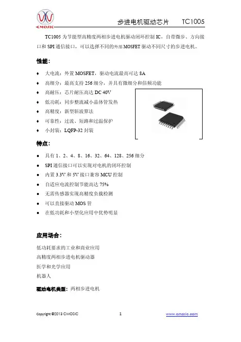
TC1005为节能型高精度两相步进电机驱动闭环控制IC ,自带微步、方向接口和SPI 通信接口,可以选择不同的外部MOSFET 驱动不同尺寸的步进电机。
性能:♦ 大电流:外置MOSFET ,驱动电流最高可达8A ♦ 高细分:最高支持256细分,并具有微细分和倍频功能 ♦ 高耐压:芯片耐压高达DC 40V ♦ 低功耗:同步整流减小晶体管发热 ♦ 高精度:新型斩波算法 ♦ 可靠性:过流、短路和过温保护 ♦ 小封装:LQFP-32封装特点:● 具有1、2、4、8、16、32、64、128、256细分 ● SPI 通信接口可以实现对电机的闭环控制 ● 内置3.3V 和5V 接口兼容MCU 控制 ● 自适应电流控制节能高达75% ● 无需传感器实现高精度负载检测 ● 可以直接驱动MOS 管● 在低功耗和小型化应用中优势明显应用场合:低功耗要求的工业和商业应用 高精度两相步进电机驱动器 医学和光学应用 机器人驱动电机类型:两相步进电机1 工作原理1.1 原理框图1.2 步进和方向控制序列发生器和SPI通过斩波的方式实现电机控制两种控制方案:第一种是步进和反向控制脉冲的控制方式,第二种是通过SPI配置参数的方式。
控制和诊断寄存器给改变电机条件和修改电机状态带来了灵活性。
内部集成了正弦和余弦发生器,在接收一个脉冲后,运动一个微步距,从而实现电机的微步运行。
1.3 SPI控制方式还有一种方式只需要通过SPI进行控制。
高级的控制和诊断功能可以灵活的控制微步的波形实现两相电流的控制,通过电机自适应实现电机平滑控制。
通过CPU查找驱动表发送给两个控制单元,低速性能得到改善,高速可在几十KHZ 至几百KHZ依靠处理器的供电,实现电机控制。
1.4 斩波驱动每个斩波周期,电机电流通过采样电压和设定值进行比较。
这种方案可以满足高动态需求,从而实现了快衰减和过零的保障。
衰减周期可以设置,过零可以通过编程得到改善。
1.5 无感负载检测高精度负载测量,无需外置传感器实现电机的机器负载,负载的测量明显减小了机器的功耗,从而使驱动器散热得到改善,提高了驱动器精度和降低了功耗。
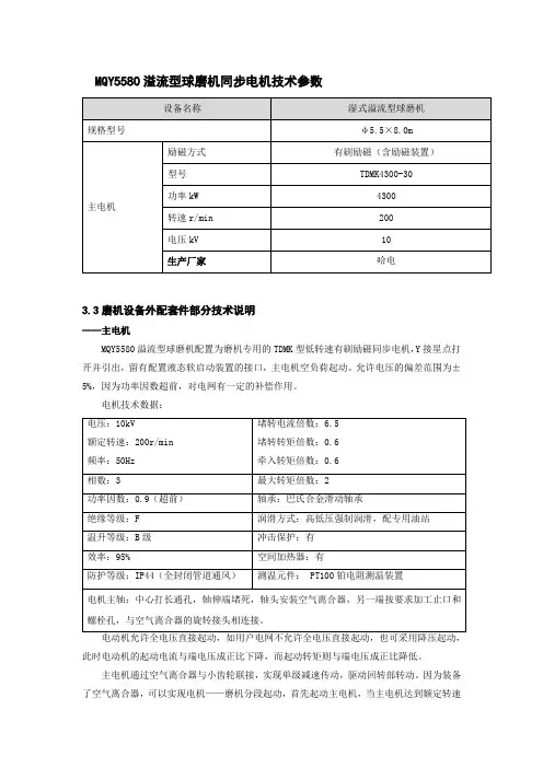
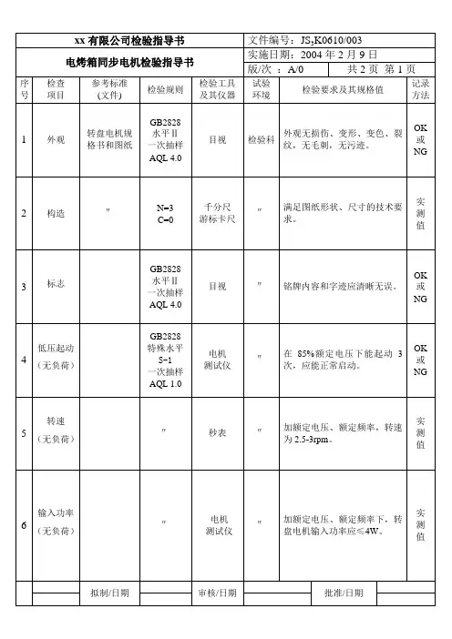
MQY5580溢流型球磨机同步电机技术参数3.3磨机设备外配套件部分技术说明——主电机MQY5580溢流型球磨机配置为磨机专用的TDMK 型低转速有刷励磁同步电机,Y 接星点打开并引出,留有配置液态软启动装置的接口,主电机空负荷起动。
允许电压的偏差范围为±5%,因为功率因数超前,对电网有一定的补偿作用。
电机技术数据:此时电动机的起动电流与端电压成正比下降,而起动转矩则与端电压成正比降低。
主电机通过空气离合器与小齿轮联接,实现单级减速传动,驱动回转部转动。
因为装备了空气离合器,可以实现电机——磨机分段起动,首先起动主电机,当主电机达到额定转速时,向空气离合器的气囊中充气,4~6秒内空气离合器的气囊达到额定压力压着闸瓦抱紧轮毂,带动小齿轮,驱动回转部回转。
分段起动可降低起动电流,改善起动条件,减少了对电网的冲击,空气离合器可使电机的起动力矩仅为额定力矩的0.4倍(一般要达到1.8~2.8倍),牵入转矩为额定力矩的0.3倍(一般为1.0倍),起动电流为额定电流的3倍左右(一般为6~7倍)。
这样电机可获得良好的机械特性,尚可避免对电源造成巨大的冲击,可相应减小选矿厂主变压器的容量,降低无功损耗,同时可以降低磨机的装机功率。
主电机进入PLC信号有定子温度、轴承温度、轴承振动、电机电流。
——有刷同步电动机微机励磁主要特点:静态励磁为全控桥整流方式,谐波较小,灭磁采用带电流回馈的逆变灭磁;标准配置互为热备用双套调节控制通道,工作通道故障时自动切换至备用通道,励磁无波动;操作电源采用交直流同时供电,两套独立开关电源;不停机更换故障插件;主回路、控制回路、触发脉冲及操作回路完全隔离;故障状态甩功能及故障消失后自动恢复;全数字化微机控制;双闭环励磁调节,可恒励磁电流或恒功率因数运行;失步保护及不减载再同步;智能化故障检测;中文菜单、触摸屏控制、数字化设置及调整参数,显示故障信息;具有RS-485串行通讯接口,方便与后台监控系统连接。
产品规格书零件号:ACC01-0000000零件名称:电机控制器总成产品型号:α-EC1060-A浙江阿尔法汽车技术有限公司60kW电机控制器规格书版/次: A / 01目录1.文档说明 (4)1.1 目的及范围 (4)1.2 术语及缩写词定义 (4)1.3 引用标准 (4)2.产品概要 (6)2.1 产品概述 (6)2.2 应用范围 (6)2.3 基本信息 (6)3. 工作环境 (7)4. 产品功能 (7)4.1电机控制器工作性能参数 (7)4.2电机控制器控制模式 (8)4.3电机控制器上下电流程 (9)4.4CAN矩阵协议 (9)4.5转矩控制 (15)4.6转速控制 (15)4.7性能限制 (16)4.8防抖 (17)4.9放电功能 (17)4.10零位自学习 (18)4.11故障保护 (19)4.12Bootloader刷写功能 (20)5.约束条件 (20)5.1 结构边界 (20)5.2 线束安装 (20)5.3 电气连接 (21)5.4 电气脚位定义 (22)6.安全特性 (24)6.1耐电压 (24)6.2绝缘阻抗 (25)7.电磁兼容特性 (25)8.质保 (25)9.可靠性 (25)10. 标签、包装、运输、储存 (26)10.1 包装 (26)10.2 运输 (26)10.3 储存 (26)11.故障检查及排除 (26)12.安全指南 (28)附录一 (30)1.文档说明1.1 目的及范围该文件介绍了360VDC,电机控制器总成产品的主要功能、性能,包括主要的参数、功能框图、约束条件、结构说明、安全规范、使用注意事项,帮助用户正确使用该电力电子单元产品。
1.2 术语及缩写词定义表1-1 术语及缩写词1.3 引用标准以下表格列出了设计所需参照的中国国家标准(简称国标)及相关的国际标准。
如所附标准被修订,请使用该标准最新版本。
表1-2 引用国内标准表1-3 引用国际标准2.产品概要2.1 产品概述本文所指电力电子单元包括:电机控制器。
1 概述本说明书提供了有关同步电机(含同步发电机、同步电动机及同步调相机)的收货、存放、安装、运行以及维护方面的说明及指导。
本说明书仅涉及各类卧式同步电机、对于立式同步电机,除了采用本说明书外,尚需专用说明书予以充实。
在本说明书或外形图中,未曾涉及到的有关安装、运行、维护方面所发生的问题,请与我厂联系。
只有严格按照外形图及使用说明书的要求,进行安装、运行及维护,方能确保电机长期、安全、可靠的使用。
电机的基本技术要求按GB 755,IEC 34-1。
1.1 电机的主要部件电机的主要部件有:定子、转子、滑动轴承(端盖式滑动轴承或座式滑动轴承)或滚动轴承、端盖、出线盒、底架、集电环或无刷励磁机等。
有时还可能有通风顶罩、冷却器、静止励磁装置等。
通风顶罩是可变部件,通过变更顶罩的结构,可以达到具体运行条件所需的各种防护等级或噪声控制等目的。
1.2 标志代号的含义1.2.1 防护等级电机的外壳防护型式,取决于安装地点及使用条件。
电机外壳的防护,由二种防护组成:a. 第一种防护:防止人体触及或接近壳内带电部分和壳内转动部件,以及防止固体异物进入电机;b. 第二种防护:防止由于电机进水而引起的有害影响。
防护等级的标志按GB 4942. 1,IEC34-5。
防护等级的标志由表征字母“IP”(气候防护型用“IPW”)及其后面的二个表征数字组成,第一位数字表示第一种防护的各个等级,第二位数字表示第二种防护的各个等级。
数字的含义分别见表1、表2。
表1 第一位表征数字表示的防护等级ּ1ּ第二位表征数字6(防海浪电机)、7(防浸水电机)、8(潜水电机)略1.2.2 冷却方法冷却方法的标志按GB 1993,IEC 34-6。
冷却方法的标志由表征字母“IC”及其后面的表征数字及字母组成。
表3列出了部分冷却方法标志的含义。
表31.2.3 安装型式电机的安装型式,是用轴线方向和固定用构件的状况来全面表达电机的安装情况。
安装型式的标志按GB 997,IEC 34-7。
通机2KW改进型单相同步发电机
绝缘材料、漆包线选用标准及技术要求
编制:
校对:
审核:
批准:
重庆阿波罗机电技术有限公司
第一部分:定子
说明:定子绝缘材料为F级。
1A、漆包线技术规格书
二、漆包线QZ(G)-2/155中代号的字母含义:
QZ ——聚酯漆;
G ——改性漆;
2 ——2级漆膜(厚漆膜);
155——温度指数为155。
1B、绝缘材料技术规格书一、表1规定了2KW改进型发电机定子所用绝缘材料:
1C、绝缘漆的技术规格书
定子所用浸渍漆规格为GT142/D改进环氧聚酯无溶剂漆,其特性、用途、
第二部分:转子
说明:转子绝缘材料为H级。
2A、漆包线技术规格书
二、漆包线QZY-2/180中代号的字母含义:
QZY ——聚酯亚胺漆;
2 ——2级漆膜(厚漆膜);
180——温度指数为180。
2B绝缘材料技术规格书
二、各绝缘材料特性、用途、性能指标:
1、聚芳砜纤维纸复合箔6550 0.20 沪Q/JB1929-84 (NMN)
聚芳砜纤维纸复合箔有两种:一种是6540属F级绝缘,一种是6550属H级
3C 绝缘漆的技术规格书
转子所用浸渍漆规格为GT142/D改进环氧聚酯无溶剂漆,其特性、用途、。
变频专用直驱式永磁同步电动机技术规格书引言直驱式永磁同步电动机是一种高效、可靠且精确的电动机,广泛应用于工业领域。
本技术规格书旨在详细描述该电动机的技术参数和性能特点,以便用户了解并正确使用该产品。
一、电机基本参数1.1 额定功率:电动机的额定功率为X千瓦,适用于各种工业场景。
1.2 额定电压:电动机的额定电压为Y伏特,可适应不同电源供电。
1.3 额定转速:电动机的额定转速为Z转/分钟,可根据实际需求进行调整。
1.4 绝缘等级:电动机采用A级绝缘,确保电机在工作过程中的安全可靠性。
二、电机性能特点2.1 高效节能:采用直驱式结构,消除了传动装置的损耗,提高了整机效率,实现了节能运行。
2.2 精确控制:通过变频器控制,电动机的转速和扭矩可精确调节,满足各种工业应用的需求。
2.3 高起动扭矩:电动机具有较大的起动扭矩,能够满足启动过程中的高负载要求。
2.4 低噪音低振动:电动机采用直接驱动方式,减少了传动装置的振动和噪音,提高了工作环境的舒适性。
2.5 高可靠性:电动机采用永磁同步技术,具有较高的抗干扰能力和稳定性,能够长时间稳定运行。
三、应用领域3.1 机床行业:电动机可用于数控机床、车床、铣床等各种机床设备,提高加工精度和生产效率。
3.2 制造业领域:电动机可应用于各种生产线和装配线,满足生产过程中的动力需求。
3.3 交通运输:电动机可用于电动汽车、电动自行车等交通工具,实现环保出行。
3.4 石油化工:电动机可应用于泵、风机等设备,提供动力支持,节约能源消耗。
3.5 其他领域:电动机还可应用于食品加工、纺织、医疗设备等多个领域,满足不同行业的动力需求。
结论变频专用直驱式永磁同步电动机具有高效节能、精确控制、高可靠性等特点,广泛应用于各个工业领域。
通过本技术规格书,用户可以了解到该电动机的基本参数和性能特点,从而选择适合自身需求的产品。
我们相信,该产品将为用户带来更高效、可靠的工作体验,并为工业发展做出积极贡献。
CONTENTS1 SCOPE 32 REFERENCES 33 SERVICE CONDITIONS 34 REQUIREMENTS 35 INSPECTION AND TESTING 76 SHIPPING, HANDLING AND STORAGE 91. SCOPEThis specification covers the minimum technical requirements for the design, manufacture, and testing of synchronous alternating current generator suitable for installation on living quarters of YUEDONG island B, the People’s Republic of China.. Any exception to the requirements of this specification shall be submitted in writing for resolution by Purchaser.2. REFERENCES2.1. GENERAAll equipment specified herein shall be designed to comply with most recent issue of the applicable IEC or U.S.A.'s standards and codes.2.2. THE LIST OF THE APPLICABLE STANDARDS AND CODES IS PROVIDED IN APPENDIX I ANDAPPENDIX II.2.3. THE FOLLOWING SPECIFICATIONS ARE CONSIDERED PART OF THIS SPECIFICATION:SPC-CC-003 External Painting For Offshore FacilitiesSPC-MA-002 Noise And Vibration SpecificationSPC-EL-001 General electrical specificationSPC-EL-014 Power, Control & Earthing CableSPC-EL-015 ELECTRICAL PACKAGED EQUIPMENT3. SERVICE CONDITIONS3.1. REFER TO THE PROJECT DESIGN BASIS FOR DETAILED ENVIRONMENTAL CONDITIONS.3.2. LOCATION: INDOORS UNCLASSFIED AREA4. REQUIREMENTS4.1. ITEM DEFINITIONThe synchronous alternating current (AC) generator required is of the industrial type, and suitable for mounting as part of a skid package.4.2. CHARACTERISTICS4.2.1. P erformanceload ratingThe generator shall have the minimum base load rating specified on the data sheet. Compliance with the data sheet requirements shall require that the power actually measured at the generator output terminals under site rating conditions be equal to or greater than the load rating specified on the data sheet.Continuous serviceThe generator shall provide a minimum of 24 months of continuous operation between major overhauls. Operation shall be at the base load rating under offshore site conditions.Parallel operationThe generator shall be suitable for parallel operation under load conditions up to the rated load, at voltage of 95% to 105% of the rated voltage.Operation under abnormal conditionsa. The generator shall be capable of withstanding a current overload of 50 % above the ratedamperage for 1 minute while maintaining the approximate rated voltage output.b. The generator shall be capable of withstanding, without damage, a 30-second, three-phaseshort circuit at its terminals when operating at rated kilovoltampere (KVA) and power factor,at 5 % over-voltage, with fixed excitation.c. The generator shall also be capable of withstanding, without damage, any other short circuitat its terminals of 30 seconds or less, provided:∙The machine phase currents under fault conditions are such that the negative phasesequence current, (I2) expressed in per unit of stator current at rated KVA, and theduration of the fault in seconds (t) are limited to values which give an integratedproduct, (I2)2t, equal to or less than 40,∙The maximum phase current is limited by external means to a value which does notexceed the maximum phase current obtained from the three-phase fault.d. The generator shall be capable of continuous operation in an unbalanced system with noneof the phase currents exceeding the rated current.e. The generator shall be capable of continuous operation with none of the phase currentsexceeding the rated current even though the voltage, frequency, and power factor exceeddesign ratings by 10 %.f. The generator shall be capable of running at least 20 % above the rated speed for 5 minuteswithout mechanical damage.g. The generator armature shall be capable of withstanding, at least twice a year, a currentoverload of 30 % above the rated amperage for a minimum of 1 minute, with overloadstarting from stabilized normal operating temperatures at rated conditions.h. The generator field winding shall be capable of withstanding, at least twice a year, a voltageoverload of 25 % above the rated voltage for a minimum of 1 minute with the overloadstarting from stabilized normal operating temperatures at rated conditions.4.2.2. P hysical characteristicsLifting lugs shall be incorporated in the generator to facilitate a single-point lift without a spreader bar, if practicable.4.3. DESIGN AND CONSTRUCT ION4.3.1. G enerala. The generator shall comply with NEMA MG 1, Motors and Generators (or IEC equivalent).b. The generator and the auxiliary equipment shall incorporate features that facilitateinterconnection with associated driver equipment.c. The generator shall be TEFC type.d. The generator shall be designed so that the rotor can be removed from the generatorenclosure without disturbing the stator.e. Embedded, encapsulated, 100-ohm platinum, resistance temperature detectors (RTD) shallbe provided to monitor the stator winding temperature at six suitable locations (two perphase).f. The generator shall be suitable for operation in a 3-phase, 3-wire, insulated (ungrounded)system.g. The generator shall be Wye connected. The neutral point shall be fully insulated from thegenerator frame and the skid frame.h. The minimum subtransient reactance shall be as specified on the data sheets.i. The telephone influence factor (TIF) of the generator, measured at the generator terminals,shall not exceed 100 balanced and 75unbalanced.j. The generator shall be capable of either synchronizing with a live circuit or closing on a dead bus.k. The generator shall have prelubricated, shielded ball bearing.4.3.2. I nsulationa. Generator insulation shall be NEMA Class F.b. The insulation shall be treated for a 100% relative humidity tropical environment and shallnot support fungus growth.c. Generator stator insulation shall be the vacuum-pressure-impregnation process (VPI) andshall receive a minimum of three complete VPI cycles. If VPI is not available, the normalinsulation shall be supplemented with extra dips and bakes for maximum protection againstmoisture and salt contamination.d. The insulation design shall be consistent with a NEMA Class B temperature rise, assumingthat the temperature of the ambient air used for cooling is 40︒C(104‘F) .4.3.3. E xcitersa. The generator shall have rotating, brushless exciters with hermetically sealed diodes andthree-phase, full-wave rectification.b. The main exciter shall be of the revolving armature type and have a nominal response notless that 1.0, with rotating rectifiers directly connected to the generator field. The rating ofthe rotating rectifiers shall be capable of withstanding transient overcurrents resulting from ashort circuit at the generator stator terminals.c. The rated output of the exciter and rectifier assembly shall be 110 % of the continuousmaximum generator excitation voltage and current rating. Each arm of the rectifier bridgeshall be capable of withstanding peak reverse voltage due to pole slipping or faultysynchronizing.4.3.4. S pace heatersGenerator and exciter anticondensation heaters shall be provided to maintain the interior temperature of the generator and exciter 5 C(41‘F) above the ambient temperature. The heaters shall be rated for a 220-Volt, 50-Hertz, single-Phase power supply.4.3.5. C abling and terminal boxesa. All cables on the generator that interconnect equipment and junction boxes shall be providedby the generator Vendor. Such cabling shall be in accordance with the specificationSPC-LD-EL-014, "Power, Control & Earthing Cable".b. Cables within the skids shall be terminated by means of compression type cable glands(supplied by the generator Vendor). the cable gland must be brass and suitable for amourcable .at same time the vendor should supply cable gland for all outgoing cables .c. All generator terminal boxes shall be totally enclosed. Control boxes shall be equipped withterminals for outgoing cables.d. One or more separate terminal boxes shall be provide for each of the following.∙Generator line∙Stator winding temperature detectors∙Generator heaters∙Generator alarm circuitse. All spare conductors shall have an individual terminal for each wire.4.3.6. V oltage regulationa. Voltage regulation and suppression equipment shall be supplied for installation in thegenerator remote control panel furnished by the generator Vendor. Regulation andsuppression equipment shall be reliable, fully suitable for control and protection of thegenerator, and of high quality.b. An acceptable method shall be provided for manual voltage regulation (MVR) control ofcoarse and fine excitation. Control shall be provided over the complete range of thegenerator characteristic output, starting from approximately zero terminal voltage on an opencircuit.c. The automatic voltage regulation(AVR) shall be provided.d. A low excitation or reverse volt-ampere reactive (VAR) relay shall be included to prevent theregulator from reducing the generator excitation level below approved (safe operating) limitsunder leading power factor conditions. This equipment shall be designed to provide both analarm and an interlock in the event of extreme low excitation when operating under eitherautomatic or manual excitation control.e. The voltage regulator shall be sensitive enough to maintain the generator terminal voltagewithin plus or minus 1.0 % of the controlled value for any deviation in output over the entireload range of the generator.f. If the generator is subjected to sudden loss of rated load, the automatic voltage regulatorshall be capable of restoring the momentary over-voltage at the generator terminals to within2 % of the rated terminal voltages within a period not exceeding3 seconds.g. The voltage regulator shall lower excitation during reduced speed operation, such as startingor idling the prime mover. Under-excitation and over-excitation limiting circuitry shall beprovided to maintain synchronism and to protect the field from excessive thermal stressesdue to loss of excitation current, including malfunction of the AVR.4.3.7. G enerator protectionThe generator shall be provided with the minimum requirements for trip initiation listed on the one line diagram.a. A remote indication of trip initiation shall be provided.b. Four volt-free contacts(two normal open, two normal close) shall be provided that willoperate when a trip is initiated. The contacts shall be connected to outgoing terminals foruse by the Purchaser.c. Trip initiation shall be designed for fail-safe operation.4.3.8. I nstrumentationVENDOR shall provide, as a minimum, the instrumentation specified on the one line diagram.instruments shall be visible from outside any enclosures without having to open access plat es or doors.4.3.9. V ibration equipmenta. As a minimum, the generator frame shall be provided with a suitable vibration switch. Thefunction of the vibration switch shall be limited to shutting down the generator unit.b. If specified, the rotor shaft shall be monitored by vibration probes suitable for X/Y readout oneach end of the rotor. Two probes shall be mounted on each bearing 90 degrees apart.4.3.10. I dentification and markinga. Corrosion-resistant, stainless steel nameplates shall be securely fastened with stainlesssteel hardware to each identifiable piece of equipment.b. Generator nameplates shall be embossed with the following information.∙Manufacturer∙Serial number, type, and frame reference∙Purchase order number∙Year of manufacture∙Rated output (continuous duty) (KVA)∙Rated power facto∙frequency (Hertz)∙Rated stator current (Amps)∙Rotor current and voltage at rated output∙Rated speed, revolutions per minute (RPM)∙Heater rating and voltage∙Subtransient reactance (%)∙Transient reactance (%)∙Class of insulation∙Phase rotation∙Weight of rotor and stator (Kgs)c. Arrows showing the direction of rotation shall be either cast on the generator case orembossed on a stainless steel plate. The plate shall be attached to the generator withstainless steel pins.4.3.11. N oiseThe generator noise limitation shall be in full accordance with the Specification SPC-LD-MA-002, "Noise And Vibration Specification".4.4. DOCUMENTATION REQUIREMENTS4.4.1. T he following information shall be submitted with the proposal.a. Completed data sheetb. Drawings of the generator showing overall dimensions and equipment withdrawal spacerequirementsc. Drawings providing locations and detailed specifications of all electrical and mechanicalinterface pointsd. Drawings delineating removal methods for major components to permit maintenance in alocal workshope. Block diagrams for AVR and exciter models, showing the transfer functions and constantsf. Generator characteristic curvesg. Requirements for generator lubricants and electrical supplies4.4.2. The following drawings shall be submitted for approval after award of contract.a. Certified approval drawings as listed in 4.4.1b. Sectional arrangement of generator and exciters showing construction of componentelementsc. Schematic and wiring diagrams of control, indication, instrumentation, and protectionsystems including terminations, interconnecting cable, and remote connected items.d. Full details of proposed inspection and testing programse. Detailed operating and maintenance instructions specific to the equipment suppliedf. Complete list showing manufacturer and model number of all instruments and accessories tobe used4.4.3. A ll following documentation shall be supplied to the Purchaser within 2 weeks of delivery of theequipment.a. Final, approved versions of all items called for in 4.4.1 and 4.4.2b. Critical speed data and torsional analysisc. Full documentation of all inspections and tests performed including all logs, curves, andcertificates. The documentation shall also note any replacement of equipment orcomponents that failed during testing.d. As-built drawings including schematics showing mechanical, structural, instrumentationcontrols, and electrical detailse. A complete list of any special tools and any handling equipment necessary to maintain thegenerator5. INSPECTION AND TESTING5.1. GENERALa. VENDOR shall carry out the tests specified in this section to ensure that the generatorcomplies with the requirements of this specification both under test conditio ns and normaloperation.b. VENDOR shall supply test certificates to the Purchaser at a date not later than the deliverydate. The test certificates shall contain details, including performance characteristics, of eachtest performed.5.2. GENERATORSa. Temperature-rise test shall be conducted on the generator. Any temperature detectionequipment in addition to the normal temperature detectors needed for conducting the testsshall be subject to approval by the Purchaser or his representative.b. Tests shall be carried out to determine the polarization index of the generator.c. Before the generator is subjected to any running tests, a dynamic balance test of thecomplete machine shall be conducted and satisfactory results demonstrated to thePurchaser or his representative. The rotor shall be run at 20 % overspeed for 2 minuets.The rotor shall be thoroughly inspected before and after the test. No part shall show signsof permanent deformation and the windings shall not show damage.d. The generator shall be assembled in the shop complete with the bearings, coolingequipment, exciters, rectifiers, voltage regulator, and controls that will be delivered with themachine. The generator shall then be driven by a calibrated prime mover and lossmeasurements taken.e. The stator and rotor winding resistance shall be measured before and after the running test.f. A generator waveform test shall be performed.g. The open-circuit characteristics shall be measured at normal speed up to 130% of the ratedvoltage and the voltage maintained for 5 minutes. Losses shall be measured at a number ofintermediate values agreed to by the Purchaser or his representative.h. Short-circuit characteristics shall be measured up to 120% of rated current during the test.Losses shall be measured at rated current and at a number of intermediate values agreed toby the Purchaser. The generator shall be run at normal speed with reduced excitation for theloss measurements.i. A short-circuit heat run shall be carried out at normal speed and rated current until steadytemperatures are obtained. Losses, temperatures, and other relevant quantities shall bemeasured throughout the test at intervals agreed to by the Purchaser or his representative.j. An open-circuit heat run shall be carried out at normal speed and rated voltage until steady temperatures are obtained. Losses, temperatures, and all other relevant quantities shall bemeasured throughout the test at intervals agreed to by the Purchaser or his representative.k. Immediately before completing the heat run, measurements of noise around the machine shall be made at positions agreed to by the Purchaser or his representative. Themeasurements shall be repeated after the heat run with the generator unexcited. With thegenerator unexcited, measurements of stator vibration of 50 and 100 Hertz shall be madeimmediately before the heat run is terminated and immediately afterwards.l. A phase-sequence test shall be made.m. An instantaneous short-circuit test shall be carried out at 70% of the rated voltage.Subtransient reactance and the TIF shall be determined (not required for type-testedgenerators).n. High voltage and insulation resistance tests on the stator and rotor winding shall be carried out after completion of all running tests. The winding under test shall be at the normalworking temperature. The generator shall be completely assembled as if in service. Theinsulation resistances shall be measured immediately before and after the high voltage tests.o. Generator efficiency shall be calculated from the results of the preceding tests. The efficiency and power losses shall be stated on the test certificate.5.3. EXCITERS5.3.1. G eneralThe following tests or measurements shall be made on all exciters.∙Resistance measurements of all windings∙High-voltage and insulation resistance measurements∙Dielectric test5.3.2. T ype-tested or first issue excitersThe following tests or measurements shall be made on exciters that have not been type-tested or are first issue.∙Open-circuit curves with and without different field∙Load curve∙Full-load temperature rise test at the maximum continuous rating of the exciters∙Excitation system loss test∙Waveform test5.4. SILICON DIODE ASSEMBLYThe following tests shall be made on diode assemblies to demonstrate compliance with this specification.a. Continuous rated and momentary overload temperature runsb. Reverse direct-current (DC) voltage test. (with the surge suppression device removed, thediode assembly shall withstand for 15 seconds a reverse voltage applied between the outputterminals at an approved DC voltage level).c. Reverse alternating-current (AC) voltage test. (with the surge suppression device removed,the diode assembly shall withstand for 1 minute a reverse voltage applied between theoutput terminals at an approved AC voltage, root mean square (RMS).d. Rectifier short-circuit test (Rectifiers shall withstand an instantaneous three-phase shortcircuit at the main generator terminals).5.5. EXCITATION CONTROL EQUIPMENTThe automatic excitation control and field suppression equipment shall be tested in conjunction with the generator and exciter to demonstrate both compliance with the specification and performance of the equipment for acceptance by the Purchaser or his representative.6. SHIPPING, HANDLING AND STORAGE6.1. EACH SHIPPING SECTION SHALL BE PROVIDED WITH SUPPORTS IN THE FORM OF SUITABLESTEEL SECTIONS, LIFTING EYES, ETC. TO MAINTAIN ALIGNMENT OF PARTS DURING SHIPPING, HANDLING, HOISTING AND INSTALLATION. LOCATION OF LIFTING POINTS SHALL BE CLEARLY MARKED ON SHIPPING CONTAINERS AND ON DRAWINGS. EACH SHIPPING SECTION SHALL HAVE ITS WEIGHT CLEARLY MARKED ON THE CONTAINER. THE WEIGHT SHALL BE IN KGS.6.2. PREPARATION FOR SHIPMENT SHALL PROTECT THE GENERATOR AUXILIARY DEVICESACCESSORIES, ETC. AGAINST CORROSION , DAMPNESS, BREAKAGE OR VIBRATION INJURY DURING TRANSPORTATION AND HANDLING.6.3. EACH SHIPPING CONTAINER SHALL BE IDENTIFIED WITH THE CONTENTS, PURCHASEORDER NUMBER AND ITEM NUMBER.6.4. INSTRUCTIONS SHALL BE PROVIDED FOR REASSEMBLY OF SECTIONS IN THE FIELD.6.5. EACH SHIPPING CONTAINER SHALL HAVE ITS WEIGHT AND LIFTING POINTS CLEARLYMARKED ON THE CONTAINERAPPENDIX IInternational Electrotechnical Commission(IEC)1 IEC 34 Rotating Electrical Machines2 IEC 72 Dimensions And Output Ratings For Rotating Electrical Machines3 IEC 185 Current Transformers4 IEC 186 Voltage Transformers5 IEC 529 Degrees Of Protection Provided By Enclosures6 IEC 85 Recommendations For The Classification Of Materials For The Insulation Of ElectricalMachinery And Apparatus In Relation To Their Thermal Stability In S erviceAPPENDIX IICodes and Standards of The Unite States1 American Petroleum Institute (API)1.1 API RP14FZ Recommended Practice For Design And Installation Of Electrical SystemsFor offshore Production Platforms2. Institute of Electrical and Electronic Engineers(IEEE)2.1 IEEE 45 Recommended Practice For Electric Installation On Shipboard3 National Electrical Manufactures Association(NEMA)3.1 NEMA MG 1 Motors And Generators4 National Fire Protection Association(NFPA)4.1 NFPA 70 National Electrical Code (NEC)5 United States Department Of Labor - Occupational Safety And Health Administration (OSHA)5.1 29 CFR 1910 General Industry OSHA Safety And Health Standards。
T1250-16/1730 10kV卧式同步电动机技术说明一、电机结构1.技术要求电机起动、运行性能达到起动运行性能指标。
电机整体绝缘等级为F极。
电机定子采用VPI真空压力浸渍绝缘处理。
电机定子绕组设有测温电阻元件Pt100,每相两个,共六个。
电机的滑动轴承的温升、噪声均达到国家标准。
电机满足励磁采装置和励磁参数及要求。
2.电机的可靠性和使用寿命:电机的大修间隔时间(累计运行时间)不少于10000小时;电机使用寿命不小于10年。
3.电机的试验电机的试验包括工厂及现场试验和检验,工厂试验和检验包括电动机的检查试验和型式试验。
工厂及现场试验和检验按最新的国家规范执行。
(1)电动机的试验方法按GB1029《三相同步电动机试验方法》;(2)电动机的噪声测定按GB10069《旋转电机噪声测定方法及限值》;3)电动机的振动测定按GB10068《旋转电机振动测定方法及限值》;4. 备品备件随机提供碳刷一套以及厂家认为应提供的备品备件。
5.专用工具随机提供一套电机安装专用工具。
- 1 -6.图纸和资料合同签订后在15天内向用户单位提供改造电机有关图纸和技术资料。
7.电机设计方案与实施7.1材料标准和电机制造标准我公司设计生产的电机及材料均依据以下最新标准和规格进行设计、制造检验和安装。
1)采用的技术标准名称和代号名称缩写中国国家标准GB国际标准化组织标准ISO国际电工委员会标准IEC中国机械工业行业标准JB中国水电行业标准SD中国电力行业标准DL中国水利行业标准SL中国法定单位及国际单位制2)材料标准及设备制造标准JB/T8667.2-97 大型三相同步电动机技术条件GB755 旋转电机基本技术要求GB/T1993-93 旋转电机冷却方式GB997 电机结构及安装形式代号GB/T13384-92 机电产品包装通用技术条件GB191 包装储运图示标志GB4772.2 电机尺寸及工差GB4831-84 电机产品型号编制方法GB4942.1 -85 电机外壳防护分级GB10068.1 旋转电机振动测定方法及限值振动测定方法GB7672.1~7672.6-87 玻璃丝包绕组线JB/T2623-1994 电机用电刷尺寸与结构型式JB/T10500.1-2005 电机用埋置式热电阻GB/T6108.3-2006/IEC60182-3:1972 绕组线基本尺寸JB/T6488.4-1995 云母带JB/T6213.1~.5-1992 电机绕组引接软电缆和软线索7.2电机结构内容7.2.1慨述卧式同步电动机为三相凸极式同步电动机,型号:T1250-16/1730 额定电压为10kV。