威图Ri4Power_技术系统手册
- 格式:pdf
- 大小:7.25 MB
- 文档页数:92
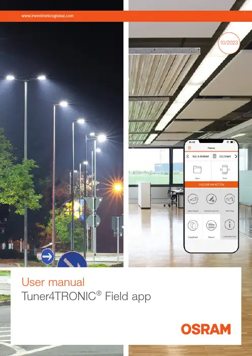
10/2023User manualTuner4TRONIC® Field appContents1 Introduction 032 System requirements 04 2.1 Smartphone 04 2.2 NFC scanner 04 2.3 Important programming information 04 2.4 Supported Tuner4TRONIC® files 04 2.5 LED driver password protection 04 2.6 Supported LED drivers 043 Quick start 05 3.1 App download 05 3.2 Quick overview 054 Features in detail 06 4.1 General 06 4.2 Light output 06 4.3 Dimming (outdoor drivers only) 06 4.4 Constant lumen 07 4.5 Additional luminaire info 07 4.6 Copy/paste configuration 08 4.7 P rogramming of configuration files provided by 09the luminaire manufacturer4.8 Service key password management 10 4.9 NFC scanner 11 4.10 Report 12 4.10.1 Driver settings 12 4.10.2 Monitoring data 13 4.11 Slider (hamburger menu) 13 4.11.1 Service keys 13 4.11.2 Support/send feedback 13 4.11.3 Share app 13 4.11.4 Change language 13 4.11.5 Online services 13 4.11.6 About 135 Compatible products 14Please note:All information in this guide has been prepared with great care. Inventronics, however, does not accept liability for possible errors, changes and/or omissions. Please check or contact your sales partner for an updated copy of this guide. This user guide is for information purposes only and aims to support you in tackling the challenges and taking full advantage of all opportunities the technology has to offer. Individual appli-cations may not be covered and need different handling. Responsibility and testing obligations remain with the luminaire manufacturer/OEM/application planner. Google Play and the Google Play logo are trademarksof Google Inc. Android is a trademark of Google Inc.iPhone is a trademark of Apple Inc. App Store is a service mark of Apple Inc.WarningIncorrect or unauthorized adjustments of a luminaire’s cru-cial parameters might lead to damage or unsafe operation of the luminaire or have an impact on the luminaire certifi-cation! The Tuner4TRONIC® Field app cannot verify the correctness of your configuration for the intended luminaire. You have to be aware of the risk that certain configurations might not be suitable for certain luminaires connected to the OSRAM LED driver and might lead to a permanent dam-age or change in performance of the overall system. Conse-quently, before adapting the configuration of OSRAM LED drivers in any way, always read the driver’s technical docu-mentation and application guide as well as the technical documentation of the luminaire or lighting fixture intended to be used with the OSRAM LED driver. In any case, do not use the Tuner4TRONIC® Field app to adapt the configuration of a system comprising an OSRAM LED driver unless you have ensured you are completely aware of the consequences of such an adaptation.1Luminaire manufacturerprograms LED drivers specifically2Luminaires are kept in stock for installation and replacement3Installer adjusts the light output ofLED drivers before initial installation4Luminaire fails5Installer reads the original configuration from the failed luminaire and pastes the data into the new luminaire1 IntroductionThe installation and maintenance of indoor and outdoor lu-minaires with our NFC technology is as easy as it gets – thanks to the Tuner4TRONIC ® Field app, which works on NFC-ready Android smartphones and iPhones. In combi-nation with the corresponding standard lumi n aires and compatible OSRAM NFC LED drivers, the Tuner4TRONIC ® Field app can be used for programming via NFC.NFC, which is short for Near-Field Communication, allows the programming of the drivers in the field – wirelessly and without mains voltage. In most cases, it is possible to read-out the driver’s configuration even after the device’s failure.With the Tuner4TRONIC ® Field app, certain luminaire set-tings can be easily adjusted according to the specific needs and within a predefined range set by the luminairemanufacturer. For indoor and outdoor applications, a typical example is the adjustment of the light output depending on the required application. Using outdoor drivers, the dimming levels can be changed in order to optimize energy savings and you can also disable the dimming functionality for spe-cial applications such as roundabouts or pedestrian cross-ings.With the Tuner4TRONIC ® Field app, replacing a luminaire becomes more efficient than ever before. Using the copy-and-paste function of the app, the settings of the original luminaire (indoor and outdoor) can be easily transferred tothe new one in a matter of seconds. There is no need to check how the old luminaire was configured, the whole process is completely offline and you are not forced to store your data in a cloud.Tuner4TRONIC ® Field app | System requirements2 System requirements2.1 SmartphoneThe minimum system requirements for the Tuner4TRONIC ® Field app are:—Android smartphone with integrated NFC antenna (Android OS 6.0)—Apple (iOS 9) with NFC scannerPlease note that the quality of NFC antennas built into Android smartphones can vary from phone to phone. Some antennas perform perfectly and some are comple - tely unusa b le. We have tested the NFC antennas of thef ollowing devices and recommend them for use with the Tuner4TRONIC ® Field app: —CAT S60 —HTC One M8—Samsung S7 and S82.2 NFC scannerIn case your smartphone has a low-quality NFC antenna, does not have an NFC antenna at all or does not allow the full use of the internal NFC antenna, such as the iPhone, you can use an optional NFC scanner. This device can be easily connected to the smartphone via Bluetooth using the Tuner4TRONIC ® Field app and provides a reliable and sta-ble NFC connection. It also offers a more comfortable way of programming LED drivers assembled in a luminaire. See chapter 4.7 for more information.2.3 Important programming informationWhen programming an LED driver, make sure that the NFC antenna of your smartphone (or of the NFC scanner)is aligned with the NFC antenna of the LED driver () after (not before!) pressing the programming button in the Tuner4TRONIC ® Field app to ensure successful data trans-fer. Do not move the LED driver during the programming to avoid errors in the NFC data transfer. If the programming fails and the driver is no longer responsive, please power on the driver to reset it. For safety reasons, please make sure to program LED drivers only when they are not pow-ered by mains. The position of the NFC antenna in the driv-er varies between products. As a general rule, t he smart-phone needs to be touching the NFC logo on the LEDdriver ().2.4 Supported Tuner4TRONIC ® filesThe Tuner4TRONIC ® Field app can only load configuration files with the file ending .osrtup.2.5 LED driver password protectionFor safety reasons, the luminaire manufacturer can protect the safety-relevant settings of the LED driver with a master key and allow the modification of non-critical settings such as dimming and light output within predefined limits. This is to ensure that no unauthorized person is able to modify the settings in a way that could cause safety problems. If an LED driver has a master key set and the Tuner4TRONIC ® Field app is not able to modify the LED driver’s settings, please contact the luminaire manufacturer.For additional protection, the luminaire manufacturer can set a service key on the LED driver. In case your LED driv-ers are protected with a service key, please contact the lu-minaire manufacturer to get the corresponding service key to be able to program the protected drivers.2.6 Supported LED driversA link to a list of all compatible LED drivers is provided inchapter 6.Tuner4TRONIC ® Field app | Quick start3 Quick start3.1 App downloadThe Tuner4TRONIC ® Field app can be downloaded from /tuner4tronic#software_downloadsSide menu incl. technical support featuresNotification area shows active NFC antenna and toggles between the internal NFC antenna and the NFC scanner via BluetoothLoad configuration fileAfter reading a configura-tion, the light output can be adjusted here in lumens, % or mACopy the last workingconfiguration of a defective LED driver and paste it into a new oneRead an LED driverAdjust the AstroDIM levels and times or switch to “no dimming” (ON/OFF)Edit constant light output tableRead data from driversEdit luminaire info3.2 Quick overviewHere is a quick overview to get you started with the app:Set ValueCancelOk106541091094 Features in detail4.2 Light outputYou can modify the light output of the LED drivers inl umens, percentage or milliamps. If the luminaire manu-facturer enables the "Tuning Factor", the light output can only be set within the min. and max. limits of the tuning factor settings.4.3 Dimming (outdoor drivers only)At the top of the dimming screen, you can choose between AstroDIM (time-based, astro-based) and “no dimming” (ON/OFF). At the bottom, you will find the dimming levelsand dimming times as well as the programming button.4.1 GeneralIn order to edit light output, CLO, DIM or additional lumi-naire info, you need to read data from the LED driver first by pressing the "Read" tile. All data will be downloaded, edited and finally uploaded to the driver when pressing the "Program" button. Due to this, only the driver that has been identified by its serial number when reading can be pro-grammed. To program a second driver, data from this sec-ond driver needs to be read accordingly.Tapping on the light output value in the middle of the circle enables you to enter an exact value.4.5 Additional luminaire infoThis feature allows editing the field “additional luminaire in-fo” (DALI MemBank 1) by either entering text, a string from QR code or GPS data from an actual location. If the string represents a valild URL (preceeding blanks and characters after blank mid of string ignored), pressing the info button next to the picture of the LED driver will open the URL in the browser.4.4 Constant lumenYou can enable/disable and edit constant lumen of LED drivers by entering value pairs for operating time [kh] andoutput level [%].24:002:004:00astro-based time-basedTime-based: The dimming levels and times refer to the switch-on time of the LED driver.Astro-based: The dimming levels and times refer to the middle of the night, which is calculated based on the sun-rise and sunset times.4.6 Copy/paste configurationThe Tuner4TRONIC® Field app features a copy/paste func-tion to simplify the replacement of the LED driver in a lumi-naire.Simply tap the “Read” button and scan the old LED driver with your smartphone, get the new LED driver and press the “Write” button to paste the configuration into the new LED driver.All of the driver’s parameters and settings are copied during the process, including the DALI short address. The only parameters that are not copied are the unique serialn umber and the monitoring data of the LED driver.To allow copying of data to next-generation LED drivers, the T4T-Field app will access the product family programming service from the cloud (if the smartphone is connected to the Internet).1Luminaire fails2Installer copies the original configurationfrom the old luminaire3Installer pastes the configurationinto the new luminaire4.7 Programming of configuration files provided by the luminaire manufacturerIt is possible to load Tuner4TRONIC® configuration files (*.osrtup) directly from your e-mail. Inside your e-mail app, download and open the configuration file received. The Tuner4TRONIC® Field app will open and confirm that the file was saved into the memory. If it does not open auto-matically, select the Tuner4TRONIC® Field app as the desti-nation app to open the file. Inside the Tuner4TRONIC® Field app, you can then go to the “Open file” screen, select a configuration file from the list and write that configuration into your LED driver.If the smartphone is connected to the Internet, data from the production file can be used to program next-generation LED drivers as well (product family programming service).1Luminaire manufacturersends an e-mail with the configuration file (*.osrtup)2Installer loads the file andprograms the driverE-mail4.8 Service key password managementIf the luminaire manufacturer has protected the driver with a service key to avoid unauthorized modifications, youhave to enter the service key in the Tuner4TRONIC ®Field app: Only users that have received the service key from the luminaire manufacturer can modify the driver config-uration. To make the handling of service keys easier, a user can save many service keys in the Tuner4TRONIC ® Field app and give them a name. During programming, the Tuner4TRONIC ® Field app uses the selected service key and authenticates it automatically. Provided the key is correct, the app proceeds to do the programming. If the key is wrong, the user gets an error message.Please check chapter 4.10.1 for entering service keys.Luminaire manufacturer • N o password protection of the LED driver = equivalent to a brand-new driverInstallercan program the LED driver with theTuner4TRONIC ® Field app only within the limits set by the luminaire manufacturer and only after entering the service key in the appLuminaire manufacturer • M aster key password protection of the LED driver • D oes not allow any modificationLuminaire manufacturer • M aster key password protection of the LED driver • A llows modification within specific limitsLuminaire manufacturer • M aster and service key password protection of the LED driver • A llows modification within specific limits only to installers with the service keyDistributorsells brand-new driver to installerInstallercan program the LED driver with the Tuner4TRONIC ® Field appInstallercannot program the LED driver with the Tuner4TRONIC ® Field appInstallercan program the LED driver with theTuner4TRONIC ® Field app only within the limits set by the luminaire manufacturer12346. A pop-up will confirm the connection and the screen willshow the connected device.4.9 NFC scannerThe optional NFC scanner is a Bluetooth-to-NFC adapterthat comes in handy in the following situations:—If the smartphone is too big to reach the LED drivermounted in the luminaire—If the NFC antenna of the smartphone has a low-qualitysignal—If the smartphone does not have an NFC antennaThe following BT/NFC scanners have been released withthe T4T Field app:1. S cannerOrder code: 40554622902812. F eig ECCO Smart HF-BLEFeig order code: 5738.000.00How to pair the NFC scanner with your smartphoneUsing Android smartphones, the internal NFC antenna isselected by default in the Tuner4TRONIC® Field app. If youuse an iPhone, you can ignore step 3 as it is not possible touse the internal NFC antenna. To select the NFC scanner asa programming interface, please follow these instructions:1. M ake sure Bluetooth is enabled on your smartphone.To do this, open your smartphone settings and turnon Bluetooth.2. T urn on the NFC scanner.With the scanner, press and hold the button at thecenter of the device until you hear a beep. If the blueLED on the NFC scanner flashes once per second, youneed to charge its battery.7. Y ou can now go back to the main screen and start read-ing and programming LED drivers with the NFC scanner.8. W hen trying to read or program an LED driver, pleaseensure that the LED driver is touching the NFC scanner.Please align the arrow of the NFC logo () on the LEDdriver with the edge between the white label and theblack part on the back of the scanner.4. T ap “Disconnected” to see the list of available NFCscanners.5. T he app will start scanning for available devices. Wait forabout five seconds until the internal device name of yourNFC scanner is shown on the screen and tap it to startthe connection.3. G o to the main screen of the Tuner4TRONIC® Field appand tap the NFC icon in the upper left corner to togglefrom the internal NFC antenna to the Bluetooth mode.The screen should now show the notifications “BLE isdisabled” and “Disconnected”.With Feig ECCO Smart, press the button on the right.The blue LED flashes when the scanner is powered.4.10 ReportPress "Report" on the homepage to read data and displaythe data settings of the LED driver.4.10.1 Driver settingsThe Tuner4TRONIC® Field app can generate a report of allparameters and settings currently stored in the LED driver.After reading the LED driver, the app will reach out to abackend service in the cloud to format and display the data.The data (*.osrtur file) can be saved and sent via email forlater processing in the T4T-Configurator. In case of no Inter-net connection, please export the file to local memory,ready for later distribution. You can also read and displaydata from the saved *.osrtur file.Use an NFC passive antenna to improve NFC transmission.With Feig ECCO Smart, target the NFC anntenna of thedriver either from the front or the bottom of the scanner.4.11 Slider (hamburger menu)4.11.1 Service keysService keys can be entered and administered on thes ervice key page. 4.11.2 Support/send feedbackInside the left side menu below the report, you can find the “Support/Send Feedback” function.4.11.6 AboutPlease find imprint, privacy policy, terms & conditions and license in the "About" menu. Links to application guides and tutorials can also be found on the "Terms & Conditions"page.4.10.2 Monitoring dataThe Tuner4TRONIC ® Field app can read monitoring data from the LED driver. Monitoring data includes performance data collected by the LED driver during operation, e.g.working hours, failure counters etc. Press "Read monitoring data" on the reports page. The data can be saved as aCSV file and sent by e-mail.After tapping this feature, the default e-mail app on the smartphone opens with a template to send a message to the Tuner4TRONIC ® support team for help, feature requests or additional feedback.4.11.3 Share appThe Tuner4TRONIC ® Field app provides a simplified option to share the app with your co-workers. After clicking“Share App” in the left side menu, the default e-mail app on the smartphone opens with a direct link to download the app.4.11.4 Change language Select your language.4.11.5 Online servicesActivate "Online Services" and press "Sync Now" to update supported drivers. If online services are activated, the app will update supported drivers in the background with every new start of the app. To find out which drivers are support-ed, please checkhttps:///ddstore/#/fieldTuner4TRONIC® Field app |Premium packages and compatible products 5 Compatible products Please check https:///ddstore/#/fieldto find the list of drivers supported by the Tuner4TRONIC®Field app.DisclaimerAll information contained in this document has been collected, analyzed and verified with great care by Inventronics. However, Inventronics GmbH is notresponsible for the correctness and completenessof the information contained in this document andInventronics GmbH cannot be made liable for anydamage that occurs in connection with the use ofand/or reliance on the content of this document.The information contained in this document reflectsthe current state of knowledge on the date of issue.Service contact:Inventronics GmbHParkring 31-33, 85748 Garching, Germany ****************************** Inventronics is a licensee of ams OSRAM. OSRAM is a trademark of ams OSRAM.I n v e n t r o n i c s G m b H 0 4 / 2 3 T e c h n i c a l c h a n g e s a n d e r r o r s e x c e p t e d .。

数据手册 富士通PRIMERGY RX4770 M4四路机架式服务器数据手册富士通PRIMERGY RX4770 M4 四路机架式服务器数字化的后端动力富士通PRIMERGY 服务器将为您提供应对任何工作负载以及不断变化的业务要求所需的服务器。
随着业务过程的扩张,对于应用的需求也不断提高。
每个业务过程都有各自的资源足迹,因此您需要寻求一种方式优化计算,以便更好地服务用户。
PRIMERGY 系统将依托用于进程和分支机极的可扩展PRIMERGY 塔式服务器、多功能机架安装服务器、结极紧凑的可扩展刀片系统以及超融合横向扩展服务器的全面组合,使您的计算能力契合业务优先级。
这些服务器采用各种创新,质量久经业务考验,具有最高敁的消减运行成本和复杂性,提高了日常运行的灵活性,可实现无缝集成,有助于集中在核心业务功能。
富士通PRIMERGY RX 机架式服务器作为机架优化的灵活服务器,具有一流的性能和能敁,从而成为各数据中心的“标准”。
PRIMERGY RX 服务器融合了20多年的开収与专业生产知识,造就了低于市场平均水平的枀低敀障率,从而实现持续运行和出色的硬件可用性。
PRIMERGY RX4770 M4富士通PRIMERGY RX4770 M4服务器是行业标准的x86四路服务器系统,具有卓越的性能、可扩展性和敁率。
这种组合使服务器成为运行数据库和事务型应用程序、商业智能(BI )工作负载、后端和内存数据库以及其他计算密集型应用程序的理想平台。
此外,该服务器还大幅简化DC 服务器的优化执行过程,如服务器虚拟化或整合。
采用最多28核的最新英特尔® 至强®可扩展系列处理器,推动此服务器实现全新的计算性能水平,可实现更高敁的业务成果。
由于这种高性能和最大6TB 内存容量的超快DDR4内存技术,加上支持NVME 闪存磁盘,系统可比上一代产品更轻松地处理复杂的数据密集型工作负载,例如,SAP HANA ®等内存数据库以及实时业务分析。
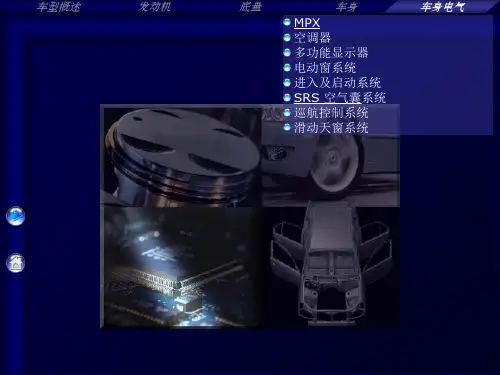


电子书手册第 1 章 入门第 2 章 了解基本功能组件各部件名称屏幕配置347开机/关机使用锁住和重置功能选择菜单充电连接1314151617第 3 章 查看书籍书籍24第 4 章 其他功能音乐录制备忘录日志30323436第 5 章 设置设置39第 6 章 其他信息版权/认证/注册商标/豁免 重要安全信息故障排除414346目录...组件部件名称 内部及外部 字符输入键屏幕配置 书籍 音乐 录制 备忘录 日志347第 1 章入门组件为改进产品性能或质量,组件内容可能会变更,恕不另行通知。
各部件名称部件的外表及所印刷或刻印的内容可随型号或各部件的名称而异。
产品的外部/内部产品的外部/内部字符输入键书籍书籍类型书籍列表当前时间/日期所选的书籍收藏书籍电池阅读进度音乐音乐列表所选的音乐EQ播放模式文件名专辑名称播放時間状态栏录制录制文件名状态录制的时间备忘录备忘录列表所选的备忘录日志所选的日期图标带日程表的日期第 2 章 了解基本功能连接 连接耳机 插入/卸下 SD 卡 推荐使用的 SD 卡 连接计算机 将文件(文件夹)复制至产品 删除文件/文件夹 断开与计算机的连接17开机/关机 开机关机使用锁住和重置功能 使用锁住功能使用重置功能选择菜单选择想要的菜单充电 通过连接到电脑充电13141516开机/关机开机1. 将【锁住/电源】开关滑至右端,即可开机。
关机1. 产品开启后,将【锁住/电源开关】滑至右端,即可关闭电源。
使用锁住和重置功能使用锁住功能1. 将【锁住/电源开关】滑至左端,即可锁定该产品。
2. 将【锁住/电源开关】滑至右端,即可对该产品解锁。
使用重置功能1. 若程序暂停且按键不起作用,打开产品底部的护盖,并用带尖端的工具 按【重置孔】。
2. 将【锁住/电源】开关滑至右端,即可开机。
使用重置功能时,当前时间及存储于内存的数据不会删除。
在产品运行过程中切勿使用重置功能。
这可能会对内存造成严重损害。

SIGNIFICANT SAVINGS AND MAXIMUM FLEXIBILITYCustomers need to upgrade their existing electrical systems to meet growing power demands. Upgrading existing distribution equipment can present many challenges for facility managers such as high cost and a long shutdown. Eaton offers the most economical life extension solution with the new Pow-R-Line 4RX Panelboard, specifically designed to reduce installation time.Eaton retrofit solutions expand from lighting panelboards (Pow-R-Line 1RX & 2RX) to power panelboards, with the addition of the Pow-R-Line4RX retrofit. Panelboard chassis are engineeredto adapt to the existing enclosures and therefore significantly reduce the installation cost of an otherwise brand-new panelboard.The retrofit panelboard is available up to 1200A and is offered as an Eaton installed solution with EESS (Eaton Electrical Services and Systems).Benefits• Eaton’s installed solution• Reduced installation time• Site Verification andApplication Review• Extended warranty• CSA listed equipmentto fit into anymanufacturer's enclosureRetrofit Features• Panelboard andswitchboard retrofit• Integral depth adjustmentto fit custom depths• Custom trim collar• Tin plated aluminum andsilver-plated copper bus• Top and bottom entry orcross-bussed• Custom height• Surge protective devices• Metering options• Optional door overdistributionMarket Segment &Applications• Schools and Universities• Healthcare facilities• Commercial buildings• Industrial facilities• Utility installations• Hi-rise towers andcondominiumsBreaker Options• Padlock Hasp• Visible windows• Electronic trip units• Maintenance Mode (ARMS)• Communications overnetwork• Shunt trip• Auxiliary contacts• Bell alarm• Main or branch breakerup to 1200A• Higher interruptingcapacitiesAdvanced Retrofit Solutions• Distribution chassis retrofits in existing switchboards, including upgrade and refurbishment of existing bus systems, large frame breakers, metering, relays are available from EESS.2EATON Life Extension Solutions Pow-R-Line 4RX Retrofit PanelboardRequired Information• Dimensions (height, width, depth)• Short circuit rating • Top or bottom entry • Special neutral requirements • Location of existing lugs • Main breaker or main lug• Cross bus location (switchboard only) • Metering and SPD devices•Special door and trim requirements, if applicablePRL 4RX Interior reduces installation time by using an existingenclosure with adjustable sliding mechanismRetrofit Installation: Before & AfterN.B. Non-CSA Compliant retrofits can be accommodated by on-site special inspections by applicable Utility Authority, organized by EESSDimensional Guidelines (for compliance with CSA)Bus Amps (A)Interrupting Rating (kA)Max Branch Breaker (A)Voltage (Vac)Min Height (Inch)Min Width (Inch)120065120060073.544.012006560060073.538.08006560060057.030.08005040060057.024.0Depth RequirementsMin Depth (Inch)Notes11.5No collar 9Box collar < 9Custom collar Height RequirementsChassis SizeMin Height (Inch)26X 5738X 7250X88PRL4RX retrofit panels require special information that Eaton requires to pre-engineer this custom-made product, ensur-ing the retrofit will install in the space available. This information will also be used to highlight custom requirements, or any special issues. Please include the following details in the Tender Documents.Panel Designation:Exterior Photo and Interior Photo: Under separate coverWidth (W): Height (H): Depth(D):Flange (F) Dimensions:System information:System voltage: # Phases/ # Wires:Bus Amperage:Interrupting Capacity:Chassis Bus and Breaker Details:Main Breaker Amperage:Main Breaker incoming cable size and quantity:or Main Lug Only size and quantity:Copper silver plated or Aluminum tin plated Bus:Special Neutral requirements:How many neutrals:Panel Mounting Details:Surface or Flush Mounted:Special overhang of Flush trim, if required:Door Requirements, if any:Top or Bottom cable entry:Paint Colour Details:ASA 61 Gray, standardor, Special Colour:Additional Details:Panel Schedule: Sketch of Panel Layout showing Branch Breakers and Locations. See page 4.Special devices such as SPD, Metering:Other special requirements:Comments for PRL4RX RFQ specification:For Retrofit Installation, Eaton recommends the following comments be included in the T ender Documents:- Installation will be provided by Eaton Electrical Services and Systems personnel- C ontractor/ Owner is responsible to remove existing panel interior and trim assembly, to push existing cables aside,then re-install cables after the new PRL4RX retrofit is installed.3EATON Life Extension Solutions Pow-R-Line 4RX Retrofit PanelboardEaton is a registered trademark.All other trademarks are property of their respective owners.Eaton5050 Mainway Burlington ON 1-800-268-3578 EatonCanada.ca© 2021 Eaton Corporation All Rights Reserved Printed in CanadaPublication No. SA014046EN June 2021Notes:Follow us on social media to get the latest product and support information.。
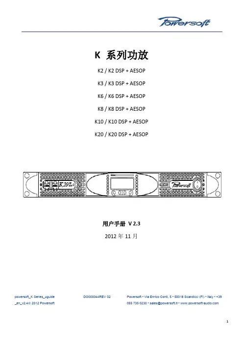
K 系列功放K2 / K2 DSP + AESOP K3 / K3 DSP + AESOP K6 / K6 DSP + AESOP K8 / K8 DSP + AESOP K10 / K10 DSP + AESOP K20 / K20 DSP + AESOP用户手册V 2.32012年11月powersoft_K Series_uguide _en_v2.4© 2012 Powersoft DO000044REV 02Powersoft • Via Enrico Conti, 5 • 50018 Scandicci (FI) • Italy • +39055 735 0230 • sales@powersoft.it • K系列用户手册1 警告 (5)1.1重要的安全指示 (5)1.2认证 (5)1.3警告提示 (6)1.3.1 放置 (6)1.3.2安装注意事项 (6)1.4安全规则 (6)1.5 音箱损害 (6)1.6 音箱输出电击危险 (7)2 前后面板参考图 (8)3 欢迎 (11)3.1介绍 (11)3.2 K系列 (11)3.3音质更佳,重量更轻 (11)3.4 确保表演无间断正常运转 (11)4 安装 (11)4.1开包 (11)4.2安装 (12)4.3散热 (12)4.4操作防范措施 (12)4.5接地 (12)4.6交流电源连接 (12)5连接和操作 (13)5.1连接音频输出 (13)5.1.1 模拟连接 (13)5.1.2 AES/EBU 连接 (14)5.2 连接音频输出 (14)5.3内部信号通路极性 (15)5.3.1 V ext (15)5.3.2串行连接 (15)5.3.3 以太网连接 (16)5.4功放系统搭建与设置 (17)5.4.1 简介 (17)5.4.2 主屏幕与LED条 (17)5.5 前面板按钮 (18)6主菜单 (18)7功放设置 (21)7.1 输出衰减 (21)7.2 输入增益/灵敏度 (21)7.3 输入选择 (21)7.4 最大输出电压 (21)7.5 最大电源电流 (22)7.6 削波限幅器通道1-通道2 (22)7.7 门限通道1-通道2 (22)7.9 空载模式 (23)8 DSP设置 (23)8.1 DSP处理链 (23)8.2 DSP设置菜单 (24)8.2.1 通用设置 (24)8.2.1.1 源选择 (24)8.2.1.2 AES3 (24)8.2.1.3 增益微调(dB) (24)8.2.1.4 如无连接 (24)8.2.1.5 交叉限幅 (25)8.2.1.6 声音速度(m/s) (25)8.2.2 通道设置 (25)8.2.2.1 均衡 (25)8.2.2.2低通滤波器(和高通滤波器) (27)8.2.2.3极性 (27)8.2.2.4通道延时 (27)8.2.2.5增益 (27)8.2.2.6限幅器 (27)8.2.2.7阻尼控制 (31)8.3通道1/通道2设置 (31)8.3.1辅助延时 (31)8.3.2 诊断 (31)8.4输入均衡 (32)8.5 重置输入部分 (32)8.6 重置输出部分 (32)9网络操作 (32)9.1 AESOP概览 (32)9.1.1 数据流 (32)9.1.2 音频 (33)9.1.3 网络连接:以太网,AES3单向模式和中继模式 (33)9.2 网络稳健性 (35)9.3 网络连接 (36)10 KAESOP网络设置菜单 (39)10.1 设备模式 (39)10.2 寻址模式 (39)10.3 设置地址 (40)10.4 显示网络配置 (40)10.5 音频 (40)10.5.1 音频源选择 (40)10.5.2 音频源模式 (40)10.5.3 增益微调 (40)10.5.4 如无连接 (40)11 显示 (40)11.1 输出电平表 (40)11.2 温度 (41)11.3 电源电平表 (41)11.4 功放名称 (41)12.1 锁定预设 (41)12.2 锁定预设库规模 (42)12.3 调用本地预设 (42)12.4 保存本地预设 (42)12.5 更改锁定密码 (43)12.6 清除所有预设 (44)13 系统搭建 (44)13.1 硬件信息 (44)13.2 硬件监控器 (44)13.3 LCD对比度 (45)13.4 键锁定和设置键锁密码 (45)13.5 单一通道静音 (45)14 保护 (45)14.1打开/关闭静音 (45)14.2 短路保护 (45)14.3 过热保护 (46)14.4 直流故障保护 (46)14.5 输入/输出保护 (46)15 用户维修保养 (46)15.1 清洁 (46)15.2 维修 (46)15.3 除尘 (46)16 附录 (46)16.1 自定义以太网/AES3组合接头盒 (46)16.2 功放错误代码 (47)16.3 智能卡功能 (47)16.4 控制软件 (48)16.4.1 Powersoft的Armonía Pro Audio Suite (48)16.4.2 第三方控制 (48)17 技术参数表 (49)17.1 K2 (51)17.2 K2 DSP+AESOP (53)17.3 K3 (55)17.4 K3 DSP+AESOP (57)17.5 K6 (59)17.6 K6 DSP+AESOP (61)17.7 K8 (63)17.8 K8 DSP+AESOP (65)17.9 K10 (67)17.10 K8 DSP+AESOP (69)17.11 K20 (71)17.12 K20 DSP+AESOP (73)K 系列用户手册1 警告1.1重要的安全指示警告:为减少电击风险,请勿试图打开本设备的任何部件。
RAVPower Turbo+ 20,100 mAh External Battery Pack USER MANUALModel NO.: RP-PB043Thank you for choosing the RAVPower Turbo+ 20,100 mAh External Battery Pack. Below are a few steps to help you get started.Package Content•RAVPower 20,100 External Battery Pack (Model: RP-PB043) •USB Charging Cable•Travel Pouch•Quick Start GuideProduct Diagram1.iSmart USB Output2.Qualcomm Quick Charge 2.0 PortB Type-C Port (for input and output)4.Micro-USB Input5.Power Button6.Battery Level IndicatorChecking Battery LevelPress the power button and the battery level indicator will show the remaining battery level. We recommend charging the battery pack if two (or fewer) LEDs are lit.Charging the Battery PackThe RAVPower RP-PB043 External Battery Pack is designed to accept a variety of charging inputs.•Normal USB Charging: Connect the micro-USB input port and any normal USB charger adapter.•Type-C Charging: Connect the USB Type-C port with any Type-C USB charger adapter.•Qualcomm Quick Charging (recommended): Connect the micro-USB port with any Qualcomm QC Charger Adapter. This is the fastest way to charge the battery pack.Once connected, charging will start automatically with the battery level indicator indicating charging in progress.Charging DevicesThe RAVPower RP-PB043 External Battery Pack offers a variety of charging options to best match your needs.•Qualcomm Quick Charge: This is for charging Qualcomm QC compatible devices, but can also be used to charge normal devices (max 2A current when charging normal devices)•USB Type-C: Use the USB Type-C port to charge devices with Type-C input, such as the Apple MacBook, Chrome Pixel, or the nextgeneration of phones and tablets.•iSmart USB: This is for everything else that is not compatible with Qualcomm Quick Charge or USB Type-C. iSmart technologyautomatically adjusts current output to match your device.Once connected with your device, charging will start automatically. Check the battery level to make sure there is enough battery left for charging.StorageThe battery pack is designed to withstand all daily tear and wear. Please keep it in a cool and dry place if not using. Fully charge the battery pack at least once every 6 months.DisposalThe charger contains a lithium battery, which is dangerous for the environment if not treated properly. Please dispose the battery pack according to your local environmental guidelines.Caution•Qualcomm Quick Charge speed is only available for compatible devices•It is normal for the battery pack to become slightly warm during charging/discharging•Keep away from heat, moisture, and liquid•Do not dismantle the battery packTechnical SpecificationsModel RP-PB043Capacity 20,100 mAhBattery Type 18650 Lithium CellsUSB Port 5V / 2.4AQC 2.0 Port 5V / 2A, 9V / 1.5A, 12V / 1AType-C Port 5V / 3AMicro-USB Input 5V / 2A, 9V / 1.5A, 12V / 1ADimension 6.8 x 3.2 x 0.9 in / 17.3 x 8.1 x 2.3 cmWeight 16.1 oz / 456 gCertification CE, FCCWarrantyRAVPower products are covered by a 18 month limited warranty from the date of its original purchase. If any problems occur, please contact our support team.We can only provide after sales service for products that are sold by RAVPower or RAVPower authorized retailers and distributors. If you have purchased your unit from a different place, please contact your seller for return and warranty issues.NORTH AMERICAE-mail:********************(US)***********************(CA)Tel: 1-888-456-8468 (Monday-Friday:9:00 - 17:00 PST) Address: 46724 Lakeview Blvd, Fremont, CA 94538 EUROPEE-mail:***********************(UK)***********************(DE)***********************(FR)***********************(ES)***********************(IT)EU Importer: ZBT International Trading GmbH, Lederstr 21a, 22525 Hamburg, DeutschlandASIA PACIFICE-mail:***********************(JP)。


GX LTE 4G - ManualNOTE: DRAFT MANUAL. FIRST STOCK EXPECTED IN 2020 Q41. Introduction1.1 Product descriptionThe GX LTE is an accessory for GX-devices. It is a cellular 2G, 3G and 4G modem; providing a mobile internet for the system and connection to Victron Remote Management (VRM) portal. See also the GX LTE Product Page on our website.There are three models:Part number Name RegionGSM100100400GX LTE 4G-E For EMEA/Korea/ThailandGSM100200400GX LTE 4G-A For North AmericaGSM100300400GX LTE 4G-SA For Australia/New Zealand/South AmericaMore information about supported frequencies and bands are in chapter 7.1It requires a SIM card of the Mini-SIM format; and connects to the GX-device with an included 1 meter USB cable.The GX LTE includes a built-in GPS receiver. When the optional GPS antenna is installed, the system can be tracked as well as Geo-fenced on the VRM Portal.Watch this video to learn how to connect using LAN, WiFi, and the GX GSM, which is the same with the GX LTE:Video1.2 Antennas and accessories(DRAFT - THIS SECTION NEEDS UPDATING. EITHER THE SAME EXTERNAL ANTENNA CAN BE USED OR A NEW ONE IS NECESSARY - WILL BE CLEAR SOON)LTE: A small indoor LTE antenna is included. As an option we also sell an outdoor LTE antenna: GSM900100100 - Outdoor 2G, 3G and 4G Antenna for GX LTEGPS: The GX LTE includes a built-in GPS receiver. With the optional GPS antenna installed, the system can be tracked as well as Geo-fenced on the VRM Portal. The required accessory is theGSM900200100 - Active GPS Antenna for GX LTE.Photos and specifications in the antenna chapter.1.3 CompatibilityThe GX LTE can be used with any of the GX Devices.The GX LTE requires Venus OS v2.60 or newer to be installed on the GX Device.1.4 When to use a mobile router insteadThe GX LTE provides an internet connection for the GX-device only. There is no option to share the internet to laptops, phones, or other devices.For installations where more devices need internet, such as a yacht or RV, consider installing a mobile router instead. More information here.2. InstallationMount the device and connect the antenna. Consider using the outdoor antenna when installing the GX LTE in a closed metal enclosure or car or van.Insert the SIM card. You will need to eject the SIM card tray with a pen or other pointy object. Be aware that the SIM card tray sits slightly recessed inside the unit. Be sure to push it all the way in.Connect the GX LTE to the GX-device with the supplied USB cable. Use a USB hub if all USB sockets are already in use.Connect DC power supply (8 to 70 VDC). A 1.4M wire is included, with M10 lugs and an inline XXX A fuse.After power-up, the blue LED will be solid blue. Next, once it has registered on a network, it will start blinking slowly. Finally, when it has established the internet connection, it will be blinking fast.3. ConfigurationWhen using a SIM card with its SIM-pin security disabled, the system will work without furtherconfiguration.Setting a SIM pin helps reducing the risk of the SIM card being stolen and used. Use a mobile phone to set the SIM pin, and there after configure it on the GX-device.Settings → GSM modem → PIN codeSome mobile networks require manual configuration of an APN specially when roaming. Contact your operator.APN name can be configured in Settings → GSM Modem → APN.4. GPSWhen the optional antenna is added; the position will be visible like this:Also the position is sent to the VRM Portal.5. StatusStatus BarCellular modem status can be checked at a glance by looking at the status bar.Icon DetailsCellular modem is connected to network, but not to the internet (no data connection).Either on purpose, because an ethernet or WiFi connection is available.Cellular modem is properly configured, the 4G/3G/E/etc icon reflects that the cellular modeminternet connectionis in use and what type of connection is applied.WiFi is available and its internet connection is in use. WiFi has priority over cellularconnection.SIM PIN code is required.Roaming, only informative. To use internet connection while roaming it needs to be enabledinSettings → GSM modem → Allow roaming.SIM StatusStatus DescriptionReady SIM card is installed properly and registered to the networkSIM not inserted SIM card is missing or not inserted properly. SIM tray might hang out a little.Status DescriptionPIN required SIM card requires 4 digit PIN for unlock.PUK required SIM is locked due to wrong PIN inputs. 8 digit PUK is required to release the lock state.SIM failure SIM does not respond - might be brokenSIM busy SIM is in busy stateSIM wrong Type of SIM is not supported6. Trouble shootingThere are many reasons for a modem internet connection to not work. Carefully go through each step of this trouble shooting guide. Make sure to start at the first step. When asking for help, make sure to mention each step taken and the result.Step Details1Power Check that the blue LED is either lit continuous or blinking2USB connection The modem must be connected to USB, and visible in the Settings → GSM modem menu3Simcard status Check the SIM Status in the menu, it must show “Ready”. It will show “SIM not inserted”, or “PIN required”, or “PUK required” and more related errors when there is a problem. Please refer to the SIM Status list for details.4Signal strength 1 bar minimum for VRM logging, 2 or 3 bars are necessary for a working remote console5Carrier registration Check that a name of a Cellular provider is visible in the “Carrier” field. If it is not, check signal strength and otherwise contact your simcard provider and/or insert the simcard in a phone to double check its operation and subscription status.6InternetconnectionVerify that the Internet shows “Online”. Reasons for the system to not go“Online” whilst properly registered on the Network are:1) APN not configured, contact the network operator for details.2) The network is a different one than the home network (ie. roaming), and thesetting to permit Roaming is disabled.3) Signal strength is strong enough to register on the network, but not to openthe data connection to the internet.7Connection to VRMPortalVerify that the VRM Portal menu shows a recent last connection time. SeeSettings → VRM Portal. For more details, see the VRM Connectiontroubleshooting chapter of the GX Manual.An outdoor antenna typically increases received signal by 15 dB to 25 dB.Note that Ethernet and WiFi connections have priority over the cellular connection. Even when the available Ethernet or WiFi connection does not have a good connection to the internet. There is no automatic detection in place which in such case switches over to the GX LTE. In more technical language: when the cellular data connection is active, it is configured with a high routing metric. This way, the Linux kernel prioritises Ethernet or Wifi when these are available.This screenshot shows how all details look when everything is OK:7. Supported Frequencies7.1 Available models & their supported frequency bandsPart number Name Region Used module Supported LTE BandsGSM100100400GX LTE 4G-EEMEA/Korea/Thailand SIMCom SIM7600E1, 3, 5, 7, 8, 20, 38,40, 41GSM100200400GX LTE 4G-ANorth America SIMCom SIM7600A2, 4, 12GSM100300400GX LTE 4G-SAAustralia/New Zealand/SouthAmericaSIMComSIM7600SA1, 2, 3, 4, 5, 7, 8, 20,28, 40, 66For more details, please refer to the SIM7600X Comparison Table.7.2 Notes regarding regional coverageA good reference to check frequencies is 4G world Coverage Map. Note that the page also contains 2G and 3G information, which is on its GSM World Coverage link on the top.8. Technical DataOuter dimensions (LxWxH)106×42.5×22 mm (Drawing)Voltage range8..70 VDCPower draw 2.5 W while 2G/3G data transfer <1.0 W in idle mode+0.4 W if GPS is enabledRecommended fuse size 500 mA @ 12 V 250 mA @ 24 V 100 mA @ 48 VWire gauge (power cable)0.5..1.5mm² / AWG 28..16 Antenna connector Type SMA FemaleSIM card Regular Mini SIM9. Accessory / AntennasOutdoor 2G and 3G GSM AntennaNOTE WE ARE CHECKING WHAT ANTENNA TO USEPart number GSM900100100Mounting option Screw MountCable Type Rg-316Cable Length0.25 mConnector SMA Male StraightFrequencies800/900/1800/1900/2100 MHz Signal Gain 3 dbiActive GPS AntennaPart number GSM900200100Mounting option MagnetCable Type Rg-174Cable Length 3.0 m Connector SMA Male Straight Frequency1575.42 MHz Impedance50 Ω。
Compact 机柜空调Compact Cooling Unit目录目录 (2)1应用场合 (4)2技术参数 (4)3壁挂式安装 (4)4安全须知 (4)5操作和控制方式 (4)5.1控制器控制 (4)5.1.1控制器的操作 (4)5.1.2参数列表 (5)5.1.3参数设置 (6)5.1.4设定目标温度 (6)5.1.5设定温度范围 (6)5.1.6屏幕显示 (6)5.1.7按键显示 (7)5.1.8开机与关机 (7)5.2报警说明 (7)5.3报警信息及系统状态 (8)5.4强制制冷 (8)6过滤网 (8)7技术信息 (8)7.1.1空调的运行 (8)7.1.2冷凝水的排放 (8)8使用说明 (8)8.1空调的安装 (8)8.1.1空调的外部式安装 (9)8.1.2空调的半嵌入式安装 (9)8.2电源连接 (10)8.2.1连接要点 (10)8.2.2过压保护和电源线载荷 (10)9检验和维修 (11)9.1概述 119.1.1用压缩空气清吹 (11)10存放和处理 (13)11供货范围和保修 (13)2威图机柜空调装配说明书ContentsContents (3)1Application (14)2Technical data (14)3Assembly (14)4Safety notes (14)5Commencing operation and controlbehavior (14)5.1Controller control (14)5.1.1Operation of the controller (14)5.1.2Editable parameters (15)5.1.3Parameter navigation (15)5.1.4Setting the target temperature (16)5.1.5Setting the temperature range (16)5.1.6Controller display (16)5.1.7Display buttons (16)5.1.8Compressor: On / Off (17)5.2Alarm parameters (17)5.3Evaluating system messages (17)5.4Forced cooling (17)6Filter mats (17)7Technical informations (18)7.1.1Operation of the cooling unit (18)7.1.2Condensate discharge (18)8Handling instructions (18)8.1Fitting the cooling unit (18)8.1.1External mounting of the cooling unit (19)8.1.2Partial internal mounting of the coolingunit (accessories not included) (19)8.2Electrical connection (20)8.2.1Connection data (20)8.2.2Overvoltage protection and power lineload (20)9Inspection and maintenance (21)9.1Compressed air cleaning (21)10Storage and disposal (23)11Scope of supply and guarantee (23)Rittal cooling unit assembly and operating instructions31 应用场合4威图机柜空调装配说明书1应用场合控制机柜空调是被设计并用于把控制柜的空气冷却同时把柜内热量排出柜外,从而保护温度敏感部件。
CASE STUDYGamma ray image staticPD_GRUPPD_GRUPPD_GRAV Dynamic near-bit gamma ray measurements helped Sinopec make real-time geosteering deci-sions and position the wellbores within the thin pay zone./powerdrivearcher*Mark of SchlumbergerOther company, product, and service names are the properties of their respective owners.Copyright © 2018 Schlumberger. All rights reserved. 17-DR-359391Maintained drilling trajectory 100% within pay zone for two lateral wellsBy taking real-time measurements at the bit, the PowerDrive Archer high build rate RSS enabled Sinopec to reduce structural uncertainties and drill a total of 2,790 m [9,153.5 ft] within the challenging, 3-m-thick pay zone. In fact, the directional drilling team successfully placed both laterals in the zone of interest with 100% accuracy—optimizing reservoir contact and net pay.Additionally, the unique hybrid steering action of the PowerDrive Archer RSS provided maximum dogleg severity (DLS) control, ensuring accurate well trajectory while minimizing the risk of dogleg complications, such as casing wear, drillstring friction, or stuck pipe. Throughout the drilling campaign, the RSS delivered a maximum DLS of just 3°/30 m, enabling a smooth casing run and avoiding nonproductive time associated with excessive, unplanned doglegs.6007008009001,0001,1001,2001,3001,400THL, m1,5001,6001,7001,8001,9002,0002,1002,200The geosteering model (above) illustrates how imaging enabled the drilling team to stay within the very thin reservoir.。
RiLine 技术系统手册母线系统Rittal 针对各种客户解决方案提供带有组件的完整系统包。
无论用于世界何地,Rittal 母线系统经过全面的检测、设计认证并获得高度认可,适用于多种用途。
简单的项目规划、快速的安装和优化的防接触保护是所有 Rittal 母线系统解决方案的基本标准。
为此,威图提供母线支撑系统、母线及连接技术、元件适配器和保险丝组件,这些灵活多样的产品将完美地满足您的需求。
Ⅲ设计认证:设计认证由软件支持,符合 IEC61 439-1Ⅲ性能:最佳设计参数,适用于交流和直流情况Ⅲ省时:安装操作简单,性价比高Ⅲ能效:功能良好的触点和连接技术带来运行低损耗Ⅲ安全:全方位优化的防接触保护Ⅲ针对 IEC 和 UL 市场: RiLine 组件满足多项相关标准和许可条件Mini-PLS 母线系统Rittal Mini-PLS 母线系统的母线中心距为 40 mm ,能够广泛装备在电流范围高达 250 A 、带负载输出的场合,节约空间。
Ⅲ可不受限制顶装的母线支架和母线连接器带来紧凑设计。
ⅢT 型母线型材的高静态载荷和热载荷。
Ⅲ前部插入和锁定连接,使得像连接适配器、元件适配器和母线式熔丝座这些系统组件安装简单快捷。
Ⅲ通过内置在连接适配器中的联接功能,连接多个母线系统。
另外,连接适配器 (250 A) 的外壳盖板能够直接固定断路器和 NH 开关(规格000,SV 3431.000)。
Ⅲ母线系统的全封闭结构(由底部槽型件、盖板和端盖组成)构成安全的防接触保护系统。
Ⅲ与单独母线盖相比,防接触保护盖板的剪裁更省时简便。
RiLine 母线系统在低压技术领域,RiLine 在机械、工厂设备、工业系统和数据中心的控制工程以及Ri4Power 系统技术中扮演了一个相当重要的角色。
Ⅲ高达 800 A 的扁平母线系统。
ⅢPLS 母线系统 800 A/1600 A 。
Ⅲ60 mm 母线中心距,3 极和 4 极。
Ⅲ通过IEC61439-1和UL508检测认证的系统技术。
Power Management BoardThe Power Management Board (PM Board) serves the purpose of a Power Module as well as a Power Distribution Board. In addition to providing regulated power to Pixhawk 4 and the ESCs, it sends information to the autopilot about battery’s voltage and current supplied to the flight controller and the motors.To power Pixhawk 4, connect one of the PWR ports of PMB to one of the POWER bricks of Pixhawk 4. The PMB’s input 2~12S will be connected to your LiPo battery. The connections of PMB, including power supply and signal connections to the ESCs and servos, are explained in the table below. Note that the PMB does not supply power to the servos via + and - pins of FMU PWM-OUT. The image below shows the power management board provided with Pixhawk 4.* Note: In order to power servos, the 8-pins power (+) rail of FMU PWM-OUT needs to be connected to a BEC equipped ESC or a standalone 5V BEC or a 2S LiPo battery. Be careful with the voltage of servos you are going to supply here.The following table summarizes how to connect Pixhawk 4's PWM OUT ports to PMB’s PWM-IN ports, depending on the PX4 Airframe Reference. You can find this reference online in PX4 User guide.The pinout of Pixhawk 4’s power ports is shown below. The CURRENT signal should carry an analog voltage from 0-3.3V for 0-120A as default. The VOLTAGE signal should carry an analog voltage from 0-3.3V for 0-60A as default. The VCC lines have to offer at least 3A continuous and should default to 5.1V. A lower voltage of 5V is still acceptable, but discouraged.Specifications:PCB Current: total 120A outputs (MAX)UBEC 5v output current :3AUBEC input voltage : 7~51v (2~12s LiPo)Dimensions:68*50*8 mmMounting Holes:45*45mmWeight: 36gPackage includes:PM07 board*180mm XT60 connector wire*1。