直线电机安装
- 格式:docx
- 大小:873.37 KB
- 文档页数:10

直线电机光栅尺安装方法
嘿,你问直线电机光栅尺咋安装呀?这事儿可得好好说道说道。
首先呢,咱得把安装光栅尺的地方给清理干净喽。
这就好比你要贴个漂亮的贴纸,那得先把墙面擦干净不是?可不能有灰尘啊、杂物啥的,不然会影响安装效果。
清理好地方后,咱就得把光栅尺拿出来啦。
这光栅尺长得就像一把长长的尺子,可别小瞧它哦,它的作用可大着呢。
把光栅尺放在要安装的位置上,比划比划,看看合不合适。
接着呢,就得开始固定光栅尺了。
可以用螺丝啊、胶水啥的,把光栅尺牢牢地固定在那里。
这就像给一个调皮的小孩戴上帽子,得戴得稳稳的,不能让它掉下来。
固定的时候可得注意力度,别太紧也别太松。
太紧了可能会把光栅尺弄坏,太松了又固定不住。
固定好光栅尺后,还得检查一下安装得正不正。
这就像你穿衣服得看看扣子扣对了没有,不能歪歪扭扭的。
可以用水平仪啊、尺子啥的,量一量,看看光栅尺是不是安装得平平整整的。
在安装光栅尺的过程中,还得小心别把它给刮花了。
这光栅尺就像个娇气的小公主,得温柔对待。
如果不小心刮花了,可能会影响它的测量精度哦。
给你举个例子哈,就好比你要安装一个相框。
你得先把墙面擦干净,然后把相框放在合适的位置上,用钉子或者胶水固定好。
固定好后,还得看看相框是不是挂得正,不能歪了。
安装直线电机光栅尺也是一样的道理哦。
总之呢,安装直线电机光栅尺需要细心和耐心。
一步一步来,别着急。
只要你按照正确的方法做,就一定能把光栅尺安装好。
嘿嘿,这下你明白了不?。

直线电机的安装目录:一、直线电机的安装设计1.1直线电机结构设计,强度与刚度1.2 直线电机走线1.3 Z 轴(垂直轴)刹车1.4 防撞设计1.5 直线电机防护设二、安装工艺2.1 直线电机安装尺寸和公差2.2 直线电机装配方法2.3 装配其它注意事项2.4 光栅尺安装位置及安装座要求2.5 光栅尺安装精度要求2.6 光栅尺的防护2.7 冷却系统一、直线电机的安装设计1.1直线电机结构设计,强度与刚度直线电机、磁板的安装位置,应当尽量设计靠近运动结构的重心位置,以平衡运动时的推力。
直线电机与磁板之间持续存在较大的磁吸力,工作台、鞍座等设计时,必须考虑有足够的强度和刚度。
同时,为避免移动部件过于笨重,应尽量考虑采用高强度的材质,以及多筋板结构。
其它结构上提高刚度的办法有:1上拱结构2导轨等支撑点尽量靠近直线电机线圈3机床的固定部分刚性尽可能高、移动部分的重量尽可能轻,因为直线电机对刚性和移动部分重量比旋转电机更敏感1.2 直线电机走线直线电机相对于旋转伺服电机的系统而言,由于其推进动力在移动部件上,所以走线较旋转伺服电机复杂,许多线缆都需要通过拖链来连接。
主要需要通过拖链的线缆有:线圈的动力线、线圈的冷却管路、光栅尺读数头的数据线(如果读数头设计在移动部件上)、导轨润滑油管路。
这些走线均需要通过拖链连接,请务必在设计时详尽考虑。
1.3 Z 轴(垂直轴)刹车直线电机应用在 Z轴(垂直轴)上时,由于重力的作用,在未通电时,或直线电机无力矩输出时,会发生掉落事故。
必须设计 Z轴的刹车装置。
为增加安全性,建议设计 Z轴平衡装置(如机械配重、氮气平衡缸等)。
1.4 防撞设计为了避免意外的撞击事故造成直线电机的损坏,直线电机两端要加防撞缓冲装置。
设计缓冲装置时须注意:缓冲装置受力点避免在线圈、滑块等精密元件上。
1.5 直线电机防护设计(1)铁屑防护直线电机的磁板,由于对铁屑有较强的吸引力,故应当在移动部件上设计铁屑的刮除装置,同时也要避免铁屑在磁板两端过度堆积。

MOUNTINGANDINSTALLATIONGUIDELINES34Important Note:The recommendations included in this Kollmorgen Selection Guide are intended to serve as general installation guidelines, and are for reference purposes only. Kollmorgen assumes no responsibility for incorrect implementation of these techniques, which remain the sole responsibility of the user.KBM(S) series motors, as well as any other Kollmorgen frameless brushless motors that are supplied as 2-piece rotor/stator kits, should be installed by the user according to the general guidelines below.User Interface ResponsibilitiesTo assure proper performance and reliability of the motor when installed in the system, the user is responsible for designing the mounting interface in the following manner:BearingsThe user-supplied bearing system in the motor application must exhibit sufficient stiffness to maintain a rigid, uniform clearance gap between the rotor and the stator under all operating conditions. Concentricity requirements noted on each model-specific Kollmorgen outline drawing should be considered by the user when sizing and selecting bearings for appropriate radial and preload forces to achieve desired motor running gap clearance and total runout. Bearings with the lowest possible friction and high quality lubricant should be chosen to minimize overall system friction, which allows optimal motor operation.Stator Mounting MaterialsA metallic housing/clamp structure is suggested to rigidly mount the stator to assure best conductive heatsinking path and proper structural integrity. Aluminum alloys are preferred due to their superior thermal conductivity and strength-to-weight ratio, although stainless steel alloys (300 series or equivalent) are an acceptable alternative for applications that are less thermally critical. Carbon steel, cast iron, 400 series stainless alloys and other magnetic flux-conducting ferrous metals are the least desirable choices for stator mounting, but can certainly be used in some cases if proper design choices are considered. Consult a Kollmorgen Engineerfor assistance if such metals must be used. Plastics or other similar thermally isolating materials are not recommended, since they adversely affect the heatsinking capacity of the system, making it necessary to significantly de-rate the motor’s performance.Rotor Mounting MaterialsThe magnetized rotor may be mounted to any metallic shaft of the user’s choice. Carbon steel and stainless steel are the most commonly used shaft materials, although aluminum alloys are occasionally used if properly designed for the intended torqueand thermal operating range. The user’s intended method of attaching the rotor to the shaft may influence the optimum material and tolerance choices for the shaft. The user’s shaft does not need to carry flux or function as a portion of the magnetic circuit to achieve rated performance when using a Kollmorgen brushless motor.GroundingWhen mounted in the application, the laminated stack (or bare metal outer sleeve) of the stator must be at the same electrical ground potential as the system chassis and the drive amplifier chassis. If this common ground path is not ensured, the application may exhibit electrical noise and also create an electrical shock hazard. The risk of shock is particularly prevalent when using high pole-count motors with large capacitance characteristics. Typically, if the stator is mounted using electrically conductive metallic components, then a robust ground path between stator stack and machine chassis is inherently achieved. Kollmorgen suggests performing a continuity check to confirm proper ground path before enabling the motor system. In some applications, depending on mounting configuration and materials chosen by the user, a separate conductive ground strap may be required. In such cases, the user is responsible for installation of the ground path and electrical verification.Mounting and Installation Guidelinesw w w.k o l l m o r g e n.c o mM O U N T I N G A N D I N S T A L L A T I O N G U I D E L I N E S35WiringKBM(S) series motors are supplied with UL-compliant unterminated flying leadwires. The user is responsible for proper leadwire routing and connection per the diagrams shown on Kollmorgen drawings. Avoid routing wires across sharp corners, pinch points or edges that may pierce the insulation. Clamp or otherwise secure wire bundle in high vibration applications and avoid wirecontact with moving/vibrating surfaces that may abrade the insulation. Provide strain relief for all wire bundles and allow room for a generous bend radius. User assumes responsibility for connector installation, crimping, soldering, shielding, sleeving or any other wire bundling or electrical interface enhancement beyond the configuration shown on the Kollmorgen outline drawing.Stator MountingKollmorgen suggests the following options for installation of the motor stator depending on torque, vibration and thermal characteristics of the application, as well as cost, ease of assembly and serviceability desired by the user.Adhesive BondIn most cases, motors in the general peak torque range up to 750 N-m may have the stator bonded in place using a structural epoxy, such as Hysol ® EA934NA, 3M ™ Scotchweld ™ 2214 or other similar adhesives. Bonding is a preferred installation technique for the KBM(S)-10XXX through KBM(S)-57XXX size stators, although shrink fitting as described in the next section is also an acceptable option. Bonding can certainly be used to secure stators larger than the aforementioned size range if desired, butrequires additional design and process considerations. To successfully utilize adhesive bonding, the user’s stator enclosure should be designed as a cylindrical cup, as shown in the illustration below, with a small shoulder for axial positioning at one end and open at the opposite end. The shoulder serves as a stop point for the stator to bank against when inserted from the open end, and should generally clear the maximum outer diameter of the winding end turn by no less than 1 mm at all circumferential points. A small internal chamfer at the open end of the housing cup simplifies stator insertion. If using a thick structural epoxy, inner diameter of the housing cup should be approximately 0.051 mm - 0.102 mm larger than the maximum outer diameter of the stator. However, the user should consult the adhesive manufacturer for proper bond line thickness, application process and curing instructions. Small grooves shown in the inner diameter of the housing in the illustration below are intended to serve as adhesive reservoirs forthick structural epoxies, but are considered optional featuresper the user’s discretion. If a retaining compound, such asLoctite ® 640™ or other similar adhesive, is preferred instead of a structural epoxy, a much tighter clearance between housing inner diameter and stator outer diameter must be controlled to maintain appropriate bond line thickness. Refer to adhesive manufacturer’s guidelines for recommendations. User assumes responsibility for selecting proper adhesive and for designing housing dimensions per expected thermal growth rate atintended temperature extremes of application. Adhesive curetemperatures should not exceed 155°C to avoid damaging themotor stator. Stator and housing surfaces should be cleanedthoroughly prior to bonding to ensure good adhesion.INSERT STATOR ILLUSTRATION II.A CONCEPTUSER'S STATOR HOUSING CHAMFER 1mm MIN.0.1020.051mmAdhesive Bond IllustrationMOUNTINGANDINSTALLATIONGUIDELINES36Mounting and Installation GuidelinesShrink FitThe user’s housing may be designed with an inner diameter that is slightly smaller than the outer diameter of the motor stator, providing an interference fit when installed. Pressing the stator into the housing at normal room temperature is not recommended because ofits laminated construction. Instead, heating the housing to achieve enough thermal growth to freely slide the stator inside is a more common technique that achieves the desired interference fit when the housing cools. Aluminum or steel housings may be used effectively to shrink fit stators across a broad peak torque range, generally from <1 N-m up to thousands of N-m. It is generally not necessary to shrink fit small diameter motors where bonding is a simpler and equally effective option, although it is acceptable to do so at the user’s discretion. For KBM(S) series motors, shrink fit is the preferred installation technique for sizes KBM(S)-60XXX throughKBM(S)-118XXX stators. Steel has a lower coefficient of thermalexpansion than aluminum, so a steel housing must be heated to amuch higher temperature than a comparable aluminum housingto achieve the desired diameter growth and stator installationclearance. In contrast, because aluminum grows much morerapidly than steel at elevated temperatures, the user should takespecial design precautions regarding size and tolerances to assurethat an aluminum housing maintains the required interference fit atthe application’s extreme high temperature. It is important to designfor sufficient dimensional interference fit, which can be influencedgreatly by many application variables and design choices, tosafely reach the motor’s maximum torque while also avoidingcrush damage to the stator. The user assumes all responsibilityfor housing design details, material selection, fit calculations andtolerance analysis for the intended application.Axial ClampingFor low torque applications, or for applications where the stator may need to be repeatedly installed and removed from the system, axially clamping may be an acceptable option. Kollmorgen does not generally recommend this technique for high shock/vibration applications, extreme temperature applications or for peak torques greater than 50 N-m without special design considerations. Thestator enclosure shown in the illustration below is very similar tothe bonding technique example shown in the first section, withapproximately 0.051 mm – 0.102 mm slip fit clearance betweenthe inner diameter of the housing and the outer diameter of thestator. When inserted, the stator banks against a shoulder insidethe housing bore that controls axial position and provides a fixedaxial clamping surface. The shoulder should clear the maximumouter diameter of the winding end turn by no less than 1 mm atall circumferential points. A separate clamp ring with the samecircumferential clearance is placed over the opposite end of thestator and bolted (typically 4 – 12 fasteners, equally spaced) to thehousing enclosure.INSERT STATORUSER'S STATOR HOUSING CHAMFER1mm MIN.USER'S STATOR HOUSINGILLUSTRATION II.C CONCEPTINSERT STATOR1mm MIN.0.1020.051CLEARANCEmmGAP REQUIRED AT ALLTOLERANCE CONDITIONSK O L L M O R G E N Shrink Fit IllustrationAxial Clamping IllustrationM O U N T I N G A N D I N S T A L L A T I O N G U I D E L I N E S37The user should design the enclosure components to ensure that, with the stator installed, an axial clearance gap exists between the clamp ring and the end of housing at all tolerance conditions. Otherwise, the clamp ring could contact the housing before the fasteners are fully tightened, resulting in insufficient axial clamping force against the stator. If desired, the small radial space between the stator outer diameter and the housing inner diameter may be filled with a thermal compound for more efficient conduction to the heatsink. However, use caution to avoid contaminating the axial clamping surfaces with grease that may reduce clamping force. If the user wishes to evaluate this axial clamping technique for motors with higher peak torque ratings, it may be necessary to increase the total surface area of the clamping regions and increase the number of clamping fasteners.BoltingSizes KBM(S)-163XXX through KBM(S)-260XXX are supplied with the stator installed in an aluminum sleeve with flange and through-holes for bolted mounting. User interfaces for these large motors should be designed per the pilot diameters and hole patterns shown on the Kollmorgen model-specific outline drawings. Several of the smaller sizes within this motor family, such as KBM(S)-10XXX through KBM(S)-45XXX range, are also supplied with the stator installed inside an aluminum sleeve, but do not include a stepped flange and are not intended to be bolted in place. For the latter range of sizes, bonding, shrinking or clamping techniques described in previous sections are appropriate.Rotor Mounting to ShaftKollmorgen’s KBM(S) series and other frameless brushless motors utilize high-performance rare earth magnets. Use extreme caution when handling or transporting to avoid injury and product damage. The attractive forces between magnetized rotors and nearby metallic objects can be extremely powerful. Improper handling can result in sudden unexpected impacts. The strong magnetic field can also damage nearby computers, display screens and memory storage devices. Keep the rotor in its shipping container or wrapped protectively until ready to install. This practice will help avoid accidents and prevent contamination such as metallic chips or debris that tend to cling to the magnets.Axial Alignment ControlKollmorgen’s model-specific outline drawings note axial alignment that must be maintained between rotor and stator whenmounted to ensure proper motor performance. The user is responsible for designing the rotor shaft, stator enclosure and bearing system to achieve the specified mounting alignment. Machined shoulders on the shaft or grooves for removable retaining rings are common ways of controlling rotor installation position. Maximum diameter of retaining rings or shaft shoulders should be kept below the rotor diameter where magnets are bonded to the steel hub.BondingGenerally, for applications where peak torque does not exceed 750 N-m, rotors can be bonded to carbon steel or stainless steel shafts. Retaining compounds, such as Loctite 640 or other similar adhesives, usually require smooth continuous interface diameters and tight fit tolerances. Structural epoxies generally require slightly larger fit clearance to allow a thicker bond line. Epoxies often benefit from grooves in the shaft/rotor interface that function as adhesive reservoirs and may be enhanced by textured machined surfaces via knurling or grit blasting. Always clean the bond joint surfaces thoroughly to ensure good adhesion. Consult adhesive manufacturer for proper bond line thickness, fit tolerances, process details and curing guidelines. To avoid partial demagnetization of the rotor, do not cure rotor/shaft bond joints at temperatures > 180°F unless rotor is nested inside the matching stator or rotor is completely surrounded by a ferrous metal keeper fixture. Contact a Kollmorgen Engineer if more information is required on this topic. Before bonding rotors to aluminum shafts, consult with adhesive manufacturer for assistance. A highly flexible adhesive with broad thermal properties may be required.K O L L M O R G E NM O U N T I N G A N D I N S T A L LA T I O N G U I D E L I N E S38Mounting and Installation GuidelinesAxial ClampingIf the user’s shaft is designed with a machined shoulder that the rotor can rigidly bank against, the rotor may be axially clamped in place using a locknut. This technique allows the rotor to be installed and removed from the shaft repeatedly, but requires a portion of the shaft to be threaded. Rotors retained by locknuts may be generally suitable for applications up to 400 N-m peak torque, although this estimate may vary greatly depending upon size and type of nut used.BoltingMotors ranging from size KBM(S)-43XXX and larger are provided with hole patterns in the rotor hub to facilitate bolted mounting. User shaft interface should be designed per the diameter, length, axial position and hole pattern noted on the Kollmorgen model-specific outline drawing.Installing Rotor Inside StatorAs previously described, magnetic forces can be extremely powerful and surprise the user when handling or installing the rotor. Extreme caution is required when placing the rotor inside the stator.Secure the StatorConfirm that the stator is securely mounted per the guidelines previously described before attempting to install the rotor. Kollmorgen recommends taping or tying the wiring bundle aside in a safe position to avoid accidental damage.Protect the Running Gap SurfacesIf left unprotected, the outer surface of the rotor may stick or “pole” to the nearest point on the inner bore of the stator due to magnetic attractive forces as the user attempts to install it. The resulting friction as the rotor slides along the inside of the stator can potentially damage the rotor band, magnets, coatings or stator bore surfaces. T o prevent damage and simplify the rotor installation process, Kollmorgen recommends first installing a thin layer of shim material, such as Mylar ® film, in the stator’s inner bore. See photos below for examples. Mylar (DuPont ® Corp. trade name) is a commonly available polyester film, often used as electrical insulation or in laminating processes, and is available in a variety of thicknesses. The Mylar film can be installed as a single piece that is wrapped entirely around the circumference of the stator bore and slightly overlapped, or multiple pieces may be inserted axially at equally spaced points. Optimum film thickness and number of shim layers required is dependent upon the gap clearance between rotor and stator for the specific motor size the user is attempting to install. Appropriately thick Mylar film shim layer(s) will keep the rotor roughly centered inside the stator bore and provides a slick surface to slide the rotor to its intended mounting position without damage.Single Mylar Shim Multiple Mylar Shimsw ww.k o l l m o r g e n.c o mM O U N T I N G A N D I N S T A L L A T I O N G U I D E L I N E S39Installing the RotorMany of the KBM(S) series rotors are too large to safely lift by hand and the attractive force as the rotor rapidly enters the stator can be too powerful to control by hand. Kollmorgen recommends using a hoist or small overhead crane to lift the rotor into position and stabilize it for safely controlled insertion into the stator. Most large KBM(S) rotors include tapped holes in the steel hub for the user to attach eye bolts to facilitate hoist lifting. Note that swiveled eye bolts, as opposed to fixed ring eye bolts, are recommended for safe lifting with hoist chain and hook interface.Inspect the Running GapAfter the rotor is properly installed and secured, remove all Mylar shim material. Carefully inspect the running gap for any debris or obstructions. If possible, spin the rotor by hand to confirm that it rotates freely.Installation AssistanceCustomers may contact Kollmorgen for assistance with application or installation problems. See rear cover of this selection guide for contact information. If desired, Kollmorgen can also design and supply custom motor installation fixtures for the user’s unique application needs. Fixture solutions are quoted separately on a case-specific basis.Electrical Wiring Interface。
直线电机的安装目录:一、直线电机的安装设计1.1直线电机结构设计,强度与刚度1.2 直线电机走线1.3 Z 轴(垂直轴)刹车1.4 防撞设计1.5 直线电机防护设二、安装工艺2.1 直线电机安装尺寸和公差2.2 直线电机装配方法2.3 装配其它注意事项2.4 光栅尺安装位置及安装座要求2.5 光栅尺安装精度要求2.6 光栅尺的防护2.7 冷却系统一、直线电机的安装设计1.1直线电机结构设计,强度与刚度直线电机、磁板的安装位置,应当尽量设计靠近运动结构的重心位置,以平衡运动时的推力。
直线电机与磁板之间持续存在较大的磁吸力,工作台、鞍座等设计时,必须考虑有足够的强度和刚度。
同时,为避免移动部件过于笨重,应尽量考虑采用高强度的材质,以及多筋板结构。
其它结构上提高刚度的办法有:1上拱结构2导轨等支撑点尽量靠近直线电机线圈3机床的固定部分刚性尽可能高、移动部分的重量尽可能轻,因为直线电机对刚性和移动部分重量比旋转电机更敏感1.2 直线电机走线直线电机相对于旋转伺服电机的系统而言,由于其推进动力在移动部件上,所以走线较旋转伺服电机复杂,许多线缆都需要通过拖链来连接。
主要需要通过拖链的线缆有:线圈的动力线、线圈的冷却管路、光栅尺读数头的数据线(如果读数头设计在移动部件上)、导轨润滑油管路。
这些走线均需要通过拖链连接,请务必在设计时详尽考虑。
1.3 Z 轴(垂直轴)刹车直线电机应用在 Z轴(垂直轴)上时,由于重力的作用,在未通电时,或直线电机无力矩输出时,会发生掉落事故。
必须设计 Z轴的刹车装置。
为增加安全性,建议设计Z轴平衡装置(如机械配重、氮气平衡缸等)。
1.4 防撞设计为了避免意外的撞击事故造成直线电机的损坏,直线电机两端要加防撞缓冲装置。
设计缓冲装置时须注意:缓冲装置受力点避免在线圈、滑块等精密元件上。
1.5 直线电机防护设计(1)铁屑防护直线电机的磁板,由于对铁屑有较强的吸引力,故应当在移动部件上设计铁屑的刮除装置,同时也要避免铁屑在磁板两端过度堆积。
直线电机的安装调试方法
1. 嘿,直线电机安装调试第一步,那就是得认真准备好场地呀!就像建房子得先有牢固的地基一样。
你可别小瞧这一步哦!比如,咱们要是在一个乱糟糟、满是杂物的地方安装,那不就像在沼泽地里盖房子,能稳吗?肯定不行呀!所以场地清理干净整洁是超级重要的啦。
2. 直线电机拿来了,得小心轻放呀,这可不是随便扔那儿就行的。
好比是呵护一个宝贝蛋,轻拿轻放它才能安好呀!想想看,要是你粗鲁对待,它能好好工作给你回报吗?肯定不能呀!所以啊,一定拿稳了放到位。
3. 安装的时候,每一个螺丝都要拧紧咯!这就跟系鞋带一样,松了可就容易出问题。
就像你跑步的时候鞋带松了,那不得摔个大跟头呀!可别偷这点懒哦!
4. 调试那可得细心再细心呀!就像给病人看病一样,得仔细检查各项指标。
比如说电机运行的速度、精度等等,一个小细节都不能放过呀,不然到时候出问题可就麻烦大啦!
5. 嘿,还记得要给直线电机做好润滑呀!这好比给汽车加机油,能让它跑得更顺畅呢!要是不做这一步,那不就像让运动员干跑不喝水,能撑多久呀?所以润滑很关键哦!
6. 连接线路的时候可不能出错呀,这就像走迷宫,得找对路才行。
万一接错了线,那不就像走错了路,还怎么到达目的地呀!一定要仔细对照图纸哟!
7. 测试的时候得全神贯注呀,看着它运行的状态,有没有异常啥的。
这可关系到后面能不能正常工作呀,就像考试一样,得认真对待才能拿高分呀,对不?
8. 要是安装调试过程中发现了问题,别慌!冷静下来解决呀!这就像遇到困难一样,慌乱有啥用呢,得积极面对去克服呀!
9. 总之呀,直线电机的安装调试可不能马虎,这里面的学问大着呢!每一步都得做好,它才能乖乖为咱工作呀!。
双y直线电机定子安装注意事项
双Y直线电机定子安装注意事项主要包括以下几点:
1、确保磁石定子表面的精度和直线度,因为这直接影响到磁板的形变量与气隙的均匀度,进而影响电机的性能。
2、在安装磁石定子时,需要注意固定螺孔的距离、最小距离以及磁石定子之间的气隙,这些因素都会影响到电机的安装精度和最终的使用效果。
3、磁石定子与线圈溜板之间的气隙大小对磁性吸引力和电机的最大推力有重要影响。
一般要求气隙的大小为0.5mm,以确保足够的磁性吸引力和推力。
4、安装前应检查机床机械安装底座平面的平直度和定子磁选机表面的平直度,确保设备基面平整度,这对于保证直线电机的安装质量和运动精度至关重要。
5、在安装过程中,还需要注意线圈的绝缘处理,确保绝缘材料的质量和可靠性,同时在使用过程中要定期检查绝缘状态,及时修复或更换损坏的绝缘材料,以避免电流泄漏或短路现象的发生。
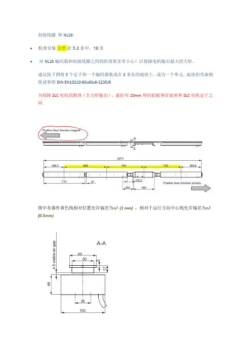
初级线圈和NL16:•检查安装公差在5.2章中,18页•对NL16编码器和初级线圈之间的距离要非常小心!以保障电机输出最大的力矩。
建议按下图将3个定子和一个编码器集成在3米长的底座上,成为一个单元,底座的弯曲刚度请参照DIN EN10210-60x60x6-S235JR为保障SLC电机的散热(全力矩输出),最好用10mm厚的铝板垫在底座和SLC电机定子之间图中各器件黄色线相对位置允许偏差为+/- (1 mm),相对于运行方向中心线允许偏差为+/-(0.5mm)•为获得较好的推力分布,电机集成单元,最好均布在环形线的直线段处次级侧:•·见5.4章,总是有南北两极交变;也包括两车之间的南北两极交变•·确保所有电车第一磁铁总是放在从相同的距离,它总是相同的磁极(南或北)•·用磁针检查每个小车的磁极顺序是正确的•·铁氧体磁体是脆的。
如果一小部分碎裂,你仍然可以使用它们。
装配前请擦拭干净•使用螺钉将磁铁整块安装在小车底部,每个直线电机最大能产生480N的推力,所以用来紧固磁块的紧固件需要核定紧固力(推荐1000N)•.用盖子保护磁块,盖子不能是铁磁材料•首先使用0.5mm的铝板或非铁磁材料保护磁块,再使初级和次级之间保持4mm的间隙(即直线电机初级和次级之间4.5mm间隙),即可获得额定的推力,间隙越小,推力越大;间隙越大,推力越小,直到7mm•如果有一个检测初级和次级之间间隙的装置是最好的;在车体上安装一个毛刷,不断对初级和次级之间进行异物清除,也是必要的•每车的长度保持在(n*100mm) +/- (1 to 4mm),不要产生累积间隙(车与车的连接有一定的可调度)5h11= 5+0,0; 5-0,075 60h11 = 6+0,0; 6-0,19。
parker直线电机使用手册parker直线电机是一种先进的电动驱动设备,具有高效、精准、稳定的特点。
本使用手册旨在为用户提供关于parker直线电机的详细操作说明和注意事项,帮助用户正确、安全地使用该设备。
正文一、产品概述parker直线电机是一种采用直线运动原理的电动驱动器,可广泛应用于机械加工、自动化装配、医疗器械等领域。
该电机具有结构紧凑、功耗低、响应速度快等优点,能够实现高精度直线运动控制。
二、安装与调试1. 安装前,请确保电机和控制器的电源已经断开,并按照说明书的要求选择适当的安装位置。
2. 仔细检查电机是否有损坏或松动的部件,如有发现问题,请及时联系售后服务。
3. 将parker直线电机正确安装到设备上,并确保固定牢固。
4. 进行电机参数的设置和调试,根据实际需求调整电机的运动速度、加速度等参数。
三、使用注意事项1. 在使用过程中,请勿超载使用电机,以免造成设备损坏或安全事故。
2. 使用前,请确保电机和控制器的电源稳定,并按照标准接线图正确接线。
3. 长时间不使用电机时,请切断电源,以免造成能耗浪费和设备损坏。
4. 请定期对电机进行维护保养,保持电机的清洁和良好的工作状态。
5. 若发现电机运行异常或故障,请及时联系售后服务,不要自行拆卸或修复。
四、售后服务1. 如果在使用过程中遇到任何问题,可随时联系售后服务。
2. 请提供详细的问题描述和相关信息,以便售后服务能够及时有效地给予帮助。
3. 售后服务将尽快解决您的问题,并提供技术支持和维修服务。
【文档结尾】本使用手册详细介绍了parker直线电机的安装、调试和使用注意事项,希望能够帮助用户正确、安全地操作该设备。
如有更多问题,请随时联系售后服务。
直线电机安装手册
直线电机是一种将电能直接转换成直线运动机械能的电力传动装置,它可以省去大量中间传动机构,加快系统反映速度,提高系统精确度,所以得到广泛的应用。
以下是直线电机的安装步骤:
1. 检查安装环境:在安装直线电机之前,请确保安装环境符合要求。
检查安装表面是否平整、干净,是否有足够的空间来安装直线电机。
2. 安装支架:根据直线电机的型号和安装方式,选择合适的支架。
将支架固定在安装表面上,确保支架稳固。
3. 安装电机:将直线电机安装在支架上,确保电机与支架之间的连接牢固。
在安装过程中,注意保护电机的电缆和连接器。
4. 连接电源和控制系统:根据电机的电源要求,将电源和控制系统连接到电机上。
确保连接正确、牢固。
5. 调整电机位置:在安装完成后,需要对电机的位置进行调整,以确保电机能够正常运行。
调整电机位置时,需要注意不要损坏电机和支架。
6. 测试电机:在安装完成后,需要对电机进行测试,以确保电机能够正常运行。
测试电机时,需要注意安全,避免发生意外。
7. 安装防护罩:如果直线电机需要防护罩,在测试完成后,需要安装防护罩。
安装防护罩时,需要注意防护罩的安装位置和固定方式。

直线电机模组安装注意事项直线电机模组是一种常用于自动化设备和机械系统中的关键部件,用于实现直线运动。
正确的安装直线电机模组对于保证设备的正常运行和延长使用寿命至关重要。
本文将介绍直线电机模组安装的注意事项和步骤,以帮助读者正确安装直线电机模组。
一、安装环境准备在开始安装直线电机模组之前,首先需要准备一个适合的安装环境。
安装环境应保持干燥、清洁,避免有尘土、水汽等杂质对直线电机模组的影响。
同时,还需要注意环境的温度和湿度,确保在规定的工作环境范围内进行安装。
二、固定基座安装直线电机模组需要通过固定基座来安装在机械系统上。
在安装之前,需要确保固定基座的平整度和垂直度符合要求,以保证直线电机模组的安装精度。
同时,还需要根据直线电机模组的尺寸和重量选择合适的固定螺栓和螺母,并使用扭力扳手按照规定的扭矩进行紧固。
三、导轨安装直线电机模组通常需要与导轨配合使用,以实现直线运动。
在安装导轨之前,需要仔细清理导轨的表面,并确保导轨的平整度和垂直度符合要求。
安装导轨时,应根据直线电机模组的尺寸和重量选择合适的定位销和螺栓进行固定,并使用水平仪和千分尺进行调整,以确保导轨与直线电机模组的平行度和垂直度达到要求。
四、接线连接直线电机模组的安装需要进行接线连接。
在接线之前,需要仔细阅读直线电机模组的接线图和说明书,确保正确理解接线方式和接线步骤。
接线时,应根据接线图进行正确的接线连接,并使用绝缘套管和绝缘胶带对接线进行绝缘保护。
接线完成后,应进行绝缘测试,确保接线的安全性和可靠性。
五、安装调试安装完成后,需要进行安装调试。
在调试之前,需要仔细检查安装的各个部件和连接是否牢固,是否存在松动或异常。
调试时,应按照直线电机模组的调试步骤和要求进行操作,调整参数和功能,确保直线电机模组的运行正常。
同时,还需要注意观察直线电机模组的工作状态和声音,以及各部件的温度和振动情况,及时发现和解决问题。
正确的安装直线电机模组对于机械系统的正常运行和性能发挥起着至关重要的作用。
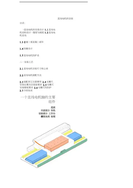
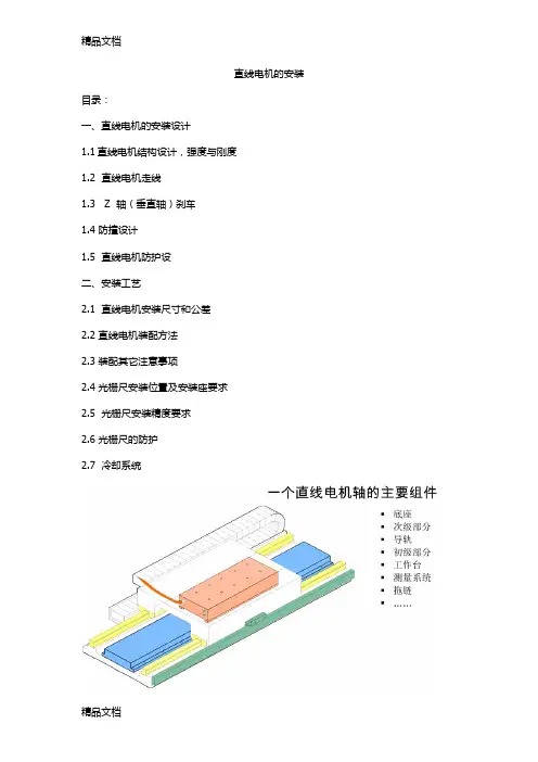
直线电机的安装目录:、直线电机的安装设计1.1直线电机结构设计,强度与刚度1.2直线电机走线1.3 Z轴(垂直轴)刹车1.4防撞设计1.5直线电机防护设二、安装工艺2.1直线电机安装尺寸和公差2.2直线电机装配方法2.3装配其它注意事项 2.4光栅尺安装位置及安装座要求 2.5光栅尺安装精度要求 2.6光栅尺的防护2.7冷却系统一个直线电机轴的主要组件底座次级部分导轨初级部分工作台测昼系统柚链一、直线电机的安装设计1.1直线电机结构设计,强度与刚度直线电机、磁板的安装位置,应当尽量设计靠近运动结构的重心位置,以平衡运动时直线电机与磁板之间持续存在较大的磁吸力,工作台、鞍座等设计时,必须考虑有足够的强度和刚度。
同时,为避免移动部件过于笨重,应尽量考虑采用高强度的材质,以及多筋板结构。
其它结构上提高刚度的办法有:1上拱结构2导轨等支撑点尽量靠近直线电机线圈3机床的固定部分刚性尽可能高、移动部分的重量尽可能轻,因为直线电机对刚性和移动部分重量比旋转电机更敏感1.2直线电机走线直线电机相对于旋转伺服电机的系统而言,由于其推进动力在移动部件上,所以走线较旋转伺服电机复杂,许多线缆都需要通过拖链来连接。
主要需要通过拖链的线缆有:线圈的动力线、线圈的冷却管路、光栅尺读数头的数据线(如果读数头设计在移动部件上)、导轨润滑油管路。
这些走线均需要通过拖链连接,请务必在设计时详尽考虑。
1.3 Z轴(垂直轴)刹车直线电机应用在Z轴(垂直轴)上时,由于重力的作用,在未通电时,或直线电机无力矩输出时,会发生掉落事故。
必须设计Z轴的刹车装置。
为增加安全性,建议设计Z轴平衡装置(如机械配重、氮气平衡缸等)。
1.4防撞设计为了避免意外的撞击事故造成直线电机的损坏,直线电机两端要加防撞缓冲装置。
设计缓冲装置时须注意:缓冲装置受力点避免在线圈、滑块等精密元件上。
1.5 直线电机防护设计(1)铁屑防护直线电机的磁板,由于对铁屑有较强的吸引力,故应当在移动部件上设计铁屑的刮除装置,同时也要避免铁屑在磁板两端过度堆积。
Packing List:A.Yaskawa Provided1)Fully assembled Sigma Trac II (Base Plate Length Varies by Order)2)Encoder Installation Manual (Fagor 14460198; 14460210)3)Fagor encoder alignment shim (0.2 mm and 0.6 mm)4)Mounting aid tool – USP-0376 (screw insertion tube) Ø15.5 (ID) x Ø19.5 mm (OD) x 100 mm (See Figure 3)**Only provided when carriage plate covers the mounting holes5)Yaskawa linear motor safety precaution manual (TOBP C230842 00B)B.Customer Provided1)Mounting bolts – Socket head cap screw recommended (see Table 1 for size & torque specs)2)Mounting base, see Page 4, Mounting Surface Recommendation**Yaskawa units are tested on laboratory grade A granite surface plate (surface flatness 0.584 µm)3) Lifting method: Jergens, Hoist Ring, FTCP, M6x1.0, 200 KG (J213405) or similar.4) Air pressure (brake models only): air pressure required to operate brake is 5.5-6.5 bar (80-95 psi), See Page 5-7CarriageType Description Material Finish Grade TensileStrength(psi)Bolt TorqueRequired(N*m)Recommended Minimum Thread EngagementStandard Base (0.5") Thick Base (1.5")AluminumPlateSteel orS.S PlateAluminumPlateSteel orS.S PlateC1, C2, C3 SHCSM8x1.25Steel BlackOxideClass12.9 140,687 41.3216 mm(20 mm boltlength)12 mm(16 mmboltlength)16 mm(46 mm boltlength)12 mm(42 mmboltlength) Steel ZincPlatedClass12.9 140,687 41.32StainlessSteel18-8(**)DIN912 39,305 11.55StainlessSteel 316DIN912 45,832 13.46A1, A2, A3 SHCSM6x1.0Steel BlackOxideClass12.9 140,687 16.9412 mm(18 mm boltlength)9 mm(15 mmboltlength)12 mm(44 mm boltlength)9 mm(41 mmboltlength) Steel ZincPlatedClass12.9 140,687 16.94StainlessSteel18-8(**)DIN912 39,305 4.73StainlessSteel 316DIN912 45,832 5.52Table 1. Bolt Torque Requirement at Specific Grade**Yaskawa uses 18-8 Stainless Steel bolts for the prevention of damage to the magnet plate.Installation:1) Carefully remove Sigma Trac II from the packaging crate by using the lifting method suggested above or a similarmethod.***CAUTION:• Do not place any magnetic objects such as iron particles close to the magnet track. Failure to observe this caution may result in injury.• Do not place any electronic devices such as clocks, magnetic cards, storage media, or measuring devices close to the magnet track. Failure to observe this caution may result in malfunction or mechanical failure of the electronic devices.• Pay attention to the magnetic attraction and confirm that there are not any magnetic objects such as iron particles attached before mounting the Sigma Trac II. Failure to observe this caution may result in injury or damage to the magnet track. (See Figure 2)2)Assemble Sigma Trac II on the mounting plate (Customer-provided)a.See Figure 1, tighten the bolts in the torque pattern shown (See Table 1 for torque requirement of eachgrade bolt)Figure 1. Sigma Trac II - Torque Pattern Order Figure 2. Sigma Trac II - Magnet Plate Caution AreaMagnaetic Plate and Carriage Omitted for clarityb. See Figure 3, for some C2 and C3 carriage / base combinations (see Table 2), it is necessary to passmounting bolts through the large holes in the carriage in order to access all mounting locations. Use of the provided screw insertion tube(s) is highly recommended to prevent any possible magnet damage to the unit.Figure 3. Screw Insertion Tube ExampleCarriage Type Base Length (Unit: mm)C2 800 900 1000 1105 --C3 1000 1105 1205 1310 1410Table 2. Mounting Tube Requirement in Slide Combination**For the C2x0800 and the C3x1000 combinations, either end-stop bumpers (Torque to 2.2 Nm when replacing) or bellows will have to be removed to be able to access specific mounting holes locations (see bolt clearance diagrams) (See Figure 4 and Figure 5)Figure 4. C2x800 Bolt Clearance DiagramFigure 5. C3x1000 Bolt Clearance DiagramMounting Surface Recommendation:This is a precision device that may flex when not securely mounted to a flat surface.1)Ensure that your mounting surface has 30 µm flatness over the area of the moving carriage for the entire surface ofthe base. Mounting surface quality will impact the life and performance of the linear stage. If any binding isdetected, check the mounting surface and adjust by shimming or lapping as necessary.**Keep in mind that these are general guidelines and the customer is responsible for installation.2)Poor accuracy may result in producing a larger load than the calculated load, and eventually lead to short life, etc.3)Reliable operation of linear motion is ensured by providing high manufacturing and mounting accuracy of mountingparts and designing a mounting structure so as to keep the accuracy and performance, while considering the required linear motion accuracy, rigidity and other related operating conditions.4)Please contact Yaskawa engineering if you have further questions or concerns.Pneumatic BrakeThe STII brake models will have a 4mm hose protruding out of the end of the cable carrier next to the sensor and power cables. Ensure that a fitting is properly securing the hose to air supply. Air supply must be clean, dry, and oil free. Brake operating pressure range is 5.5 – 6.5 bar (80 – 95 psi).Servomotor brake control for Yaskawa SERVOPACKs is handled by an external relay or SSR (solid state relay) controlled by the /BK output from the SERVOPACK. The exception to this is the Sigma-7 400V SERVOPACK with holding brake option “026” which has a built in relay for controlling the brake. Figure 6 below provides an overview of how to design a recommended brake circuit and parameterize the SERVOPACK to use the brake effectively and reliably. The brake signal should control a solenoid valve that provides air to the pneumatic brake on the Sigma Trac. It is important to note that the /BK output can only supply 50mA, the brake coil is an inductive load, and if the brake is cycled every 10 seconds or sooner, an SSR is recommended instead of a relay.Figure 6: Brake Relay CircuitPneumatic Brake (Continued)The Brake Release Time will be used in the user’s motion controller program to delay motion until the brake has been fully released. The /BK output turns ON as soon as the SERVOPACK enables the Servomotor. It is recommended to wait for at least 50ms plus the brake release time before commanding motion.The Brake Close Time will be used to set Pn506 (Brake Reference-Servo OFF Delay Time). Pn506 sets the time for howlong the motor stays enabled after the servo off command. This is used for applications in which the load might fall with the motor disabled and the brake released. Set this to the time it takes for the brake to close, plus 50ms to account for delays.Note: The motor must be stopped before the servo off command. A time delayed safety relay should be used so that the motion controller can decelerate a moving servomotor before the SERVOPACK is given a controlled servo off command.Parameter for /BK Output SelectionParameter Pn50F.2 determines the SERVOPACK output used for the /BK signal.•Make sure there is no other functions for that output•If you allocate more than one signal to the same output connector pin, a logical OR of the signals is output. Allocate the /BK signal to its own output connector pin, i.e., do not use the same output terminal for another signal.•For example, never allocate the /TGON (Rotation Detection) signal and /BK signal to the same output connector pin. If you did so, the /TGON signal would be turned ON by the falling speed on a vertical axis, and the brake would notoperate.The default setting for Pn50F.2 varies by the interface of the SERVOPACK•SGDV/SGD7So Analog voltage/pulse train reference▪/BK signal is disabled by default▪CN1-25 and CN1-26 is the first output, but has two default signals that need to be disabled or moved before /BK can be allocated.o/COIN (Positioning Completion Output) Pn50E.0 = 0 to disableo/V-CMP (Speed Coincidence Output) Pn50E.1 = 0 to disableo/BK (Brake Output) Pn50F.2 = 1 for CN1-25 and CN1-26o MECHATROLINK-II/MECHATROLINK-III/EtherCAT/Option▪CN1-1 and CN1-2•SGD7Wo200V (MECHATROLINK-III)▪Axis A: CN1-23 and CN1-24▪Axis B: CN1-25 and CN1-26o400V (MECHATROLINK-III/EtherCAT)▪Axis A: CN1-1 and CN1-2▪Axis B: CN1-23 and CN1-24•SGDV with DC Power Inputo Analog voltage/pulse train reference▪/BK signal is disabled by default▪CN1-7 and CN1-11 is the first output, but has two default signals that need to be disabled or moved before /BK can be allocated.o/COIN (Positioning Completion Output) Pn50E.0 = 0 to disableo/V-CMP (Speed Coincidence Output) Pn50E.1 = 0 to disableo/BK (Brake Output) Pn50F.2 = 1 for CN1-7 and CN1-11o MECHATROLINK-II/MECHATROLINK-III▪CN1-11 and CN1-5SGD7 400V Hardware Option "026" adds a built-in brake relay to the SERVOPACK•Pn023.0 = 0 (Use the built-in brake relays.)•SGD7W with built-in brake relay only supports Axis A•Built-in Brake Relay Specificationso Service life (number of operations): 30,000 operationso Allowable number of operations: 30 operations per minute max.o No external suppression is needed as it is already built-in。
直线电机模组安装步骤直线电机模块由磁性板(定子)、线圈(线圈滑板)、磁极位置检测单元(使用增量式编码器时)、磁性板表面未抛光钢护罩、光学切断尺等组成。
运动的原理是基于交流电在磁场中的运动,而运动的原理是基于交流电在磁场中的运动,从而控制位置。
其中永磁体采用了光切割机作为位置反馈元件。
这是因为线圈(或磁板)的运动是由磁场和励磁线圈在磁场中的相互作用完成的。
因此,磁通量的大小与电机的控制力和位置控制精度密切相关。
因此,直线电机模块的安装精度在很大程度上决定了电机的特性。
直线电机模组安装步骤下面是安装直线电机模块的主要步骤:1. 检查机床机械安装底座平面的平直度。
2. 检查定子磁选机表面的平直度。
3.真空吸尘器清洗数控车床安装的表层和直夹板的表层。
4. 预安装磁电机定子。
A、将所有电磁电机定子安装在数控车床上,用力矩扳手拧紧,用不锈钢板M8X25螺钉作为地脚螺栓,拧紧力矩为25N。
B.检查安装磁铁的表面精度和直线度。
表面精度测定方法:将大理石平台置于磁体表面,测定大理石平台的高差。
这个过程要注意的是:磁板的形状自变量和磁密度的精度是成正比的,因此,定子的定子表面的精度和平行度也要注意。
另外,磁电机的定子如果有太多可能会对磁性板造成损坏。
5. 精确测量伺服电机安装的方位角规格。
计算操作台与电磁线圈之间的电磁线圈滑板所需要的垫片厚度,并对垫片进行模具修复。
确保电磁线圈与磁体之间的磁密度为0.8mm(其中磁体的安全防护板为0.3mm)。
6. 调整磁板之间的磁密度在安装磁板的整个安装过程中,一定要注意磁板的旋光方向,另外,针对磁板中间的磁密度大小一定要进行适当的调整。
现在有很多人还不清楚这个光栅尺该安装在直线电机哪个部位呢?带你了解直线电机的光栅尺安装方法。
直线电机的光栅尺的安装更加灵活,可以安装在设备的不同位置。
主尺一般安装在机床上的工作台,读数头安装在机床上,尽量安装在主尺的下方。
安装方式必须注意切屑、切削液和油溅的方向。
如果由于安装位置限制而必须平头安装,则必须增加额外的密封,另外,通常情况下,读数头应尽量安装在相对机床的静态部件上,此时,输出线不易移动固定,而直尺应安装在相对的运动部件上。
安装光栅尺传感器时,传感器不能直接安装在粗糙的机床身上,更不能安装在油漆机身的底部。
将光栅尺和读数头分别相对运动安装在机床上的两个部件上。
用千分表检查机床工作台主尺安装面与导轨运动方向的平行度。
仪表安装在机床上,工作台移动。
平行度要求在0.1mm~1000mm之间。
如不能满足此要求,则需设计加工光栅尺底座。
底座要求如下:(1)、应增加与光栅尺长度相同的底座。
(2)、底座需经过铣磨加工,保证其平面平行度在0.1mm~1000mm之间。
另外,还需要加工一个尺体底座相等的读数头底座。
读数头底座与尺体底座的总的误差应大于±0.2mm。
安装时调整读数头位置,使读数头与光栅尺体平行度约为0.1mm,读数头与光栅尺体的间距约为1-1.5mm。
2、光栅尺安装,将光栅尺用螺丝固定咋机床工作的安装面上安装,但拧不紧时,将千分表固定在机床上,移动工作台。
调整平面的运动方向和机床的导轨的千分尺测量,螺钉位置的并行性调整,主要的主尺平行度是在0.1mm-1000mm彻底螺丝收紧。
3、在安装光栅尺主尺时,应注意一下三点:(1)、安装主尺时,如果安装的光栅尺长度在1.5m以上,则应只在两端安装在两端,应在整个主尺主题上提供支撑。
(2)、带底座安装后,用夹子夹住尺子的中点。
(3)、当无法安装时,要用光栅尺上粘贴玻璃胶,使基尺与主尺固定。
4、安装光栅尺读数头,首先要确保读数头的基面满足安装要求,然后再安装读数头。
广州微型直线电机使用方法
广州微型直线电机是一种小型电动机,常用于精密机械设备中,具有体积小、转速高、噪音低等优点。
以下是广州微型直线电机使用方法:
1. 接线:根据电机的接线图进行接线,一般需要接两根电线,注意正负极的连接。
2. 控制:广州微型直线电机一般需要使用PWM控制器进行控制,可以通过调节PWM信号的占空比来控制电机的转速和方向。
3. 安装:安装电机时需要注意电机的方向和位置,以确保电机能够正常运行,同时还需要注意电机的散热问题,可以在电机周围增加合适的散热片或散热风扇。
4. 维护:广州微型直线电机使用时需要定期清洁和润滑,以延长电机的寿命。
同时,还需要注意电机的电压和电流是否合适,不能超过电机的额定值。
以上是广州微型直线电机使用方法,希望对大家有所帮助。
- 1 -。
直线电机的安装目录:
一、直线电机的安装设计
1.1直线电机结构设计,强度与刚度
1.2 直线电机走线
1.3 Z 轴(垂直轴)刹车
1.4 防撞设计
1.5 直线电机防护设
二、安装工艺
2.1 直线电机安装尺寸和公差
2.2 直线电机装配方法
2.3 装配其它注意事项
2.4 光栅尺安装位置及安装座要求
2.5 光栅尺安装精度要求
2.6 光栅尺的防护
2.7 冷却系统
一、直线电机的安装设计
1.1直线电机结构设计,强度与刚度
直线电机、磁板的安装位置,应当尽量设计靠近运动结构的重心位置,以平衡运动时的推力。
直线电机与磁板之间持续存在较大的磁吸力,工作台、鞍座等设计时,必须考虑有足够的强度和刚度。
同时,为避免移动部件过于笨重,应尽量考虑采用高强度的材质,以及多筋板结构。
其它结构上提高刚度的办法有:
1上拱结构
2导轨等支撑点尽量靠近直线电机线圈
3机床的固定部分刚性尽可能高、移动部分的重量尽可能轻,因为直线电机对刚性和移动部分重量比旋转电机更敏感
1.2 直线电机走线
直线电机相对于旋转伺服电机的系统而言,由于其推进动力在移动部件上,所以走线较旋转伺服电机复杂,许多线缆都需要通过拖链来连接。
主要需要通过拖链的线缆有:线圈的动力线、线圈的冷却管路、光栅尺读数头的数据线(如果读数头设计在移动部件上)、导轨润滑油管路。
这些走线均需要通过拖链连接,请务必在设计时详尽考虑。
1.3 Z 轴(垂直轴)刹车
直线电机应用在 Z轴(垂直轴)上时,由于重力的作用,在未通电时,或直线电机无力矩输出时,会发生掉落事故。
必须设计 Z轴的刹车装置。
为增加安全性,建议设计Z轴平衡装置(如机械配重、氮气平衡缸等)。
1.4 防撞设计
为了避免意外的撞击事故造成直线电机的损坏,直线电机两端要加防撞缓冲装置。
设计缓冲装置时须注意:缓冲装置受力点避免在线圈、滑块等精密元件上。
1.5 直线电机防护设计
(1)铁屑防护
直线电机的磁板,由于对铁屑有较强的吸引力,故应当在移动部件上设计铁屑的刮除装置,同时也要避免铁屑在磁板两端过度堆积。
(2)切削液防护
直线电机的线圈不是完全防水的结构,接线端子上粘上切削液后,也容易造成短路漏电的事故。
所以,为防止这种情况出现,结构设计上需考虑:
※结构设计上,有防止切削液进入的结构
※线圈安装面上打硅胶也是一种简单有效的防水办法
二、安装工艺
在设计磁板和线圈的安装面时,应尽量考虑如下几点:
※磁板的安装面高于铸件平面,防止铁屑在磁板堆积。
※侧面加工安装基准,方便安装。
特别注意:
直线电机导轨安装精度要求很高,安装面一般都是用磨床磨出来的,导轨平行度最好保证在0.005mm以内。
2.1 安装尺寸和公差
2.2 装配方法
2.3 装配其它注意事项
直线电机与磁板之间有强磁性,装配时务必注意:
※不要佩戴容易被磁化的卡片,这会导致卡片磁化失效。
※由于磁板强磁性,装配好后,表面最好盖一层纸板,防止铁屑等掉落到磁板上,这会导致清理难,并容易划伤磁板表面。
※注意正确的装配顺序,不要让线圈吸合到磁板上,这样会导致拆开困难。
※磁板之间的堆放,请隔离足够厚的泡沫板或者纸板,防止磁板相互之间吸合,万一吸合上了,非常难拆开。
※作业时务必注意,手指万一被两个磁板夹住,将会受伤。
2.4 光栅尺安装位置及安装座要求
光栅尺安装方式,安装位置,安装精度对机床静态精度和动态精度影响很大,需要特别注意:
1.光栅尺安装位置尽量靠近直线电机,最好安装在导轨内直线电机的旁边。
这样,可
以减少误差,以获得最优的反馈控制效果。
2.光栅尺尺身的安装面/座有 3 种方式,床身安装面,过渡板安装面和支撑安装座;
3.安装效果最好的是床身安装面,光栅尺安装面与导轨安装面是同时加工出来的。
此种安装不易共振,安装精度容易保持。
4.如果床身上没有合适的安装面,可以考虑使用过渡板安装面,这个过渡板需要保
证足够的刚度(12mm厚度)和平面度(2 条以内)。
5.安装座方式较难调整,且容易共振;所以需要使用精度较高的加工件,且在设计
时需要考虑在 2个方向上的调整方式。
6.光栅尺读头的安装面要求与尺身类似。
2.5 光栅尺安装精度要求
光栅尺安装精度主要体现在以下几点上:
1.尺身上表面与运动方向的平行度(10 条以内,高精度要求时,3 条以内)
2.尺身侧面与运动方向的平行度(10 条以内,高精度要求时,3条以内)
3.读头与与尺身侧面的平行度(1 条以内)
4.读头与尺身的上表面的平行度(1 条以内)
5.读头与尺身的距离(1+/-0.5mm, 高精度要求时,1+/-0.1mm以内。
2.6 光栅尺的防护
可以从以下几方面考虑:
※光栅尺的安装位置,结构允许的话,在行程上可以设计安装在远离加工区域的地方,但同时要尽可能的减小阿贝误差。
※光栅尺的外部,应有足够的防护外罩,防止切削液流到尺体上;同时,光栅尺的安装方向,尽量使光栅尺的开口侧向或向下,开口不要正对铁屑及切削液飞溅的方向,
以防止光栅尺污染。
※光栅尺的安装可以加装压缩空气进行密封,但是压缩空气必须经过特别的过滤和干燥,其质量必须符合要求,在光栅尺这一段的气路上,应当安装自动检测气路气压的
反馈元件,当气路气压低于设定值时,发出报警。
2.7 冷却系统
推荐使用水冷,(监控 pH 水平),一些添加剂加入水中防止侵蚀,
有铁心直线电机数据都是基于水冷条件给出,也可以使用油冷或风冷(不推荐)。
考虑到环境温度,实现恒温调节。
冷水机组
不要使用机床的冷却剂。
力士乐推荐使用来自德国NALCO公司的成品冷却液。
如果没有条件,可以在水中加入一些添加剂用于防止对设备的侵蚀。