baldor直线电机选型手册
- 格式:pdf
- 大小:1.40 MB
- 文档页数:62

如何进行直线电机选型直线电机选型——最大推力和持续推力计算目录直线电机选型 (2)——最大推力和持续推力计算 (2)概述 (4)三角模式 (4)梯形模式 (5)持续推力 (5)计算公式 (5)例子 (6)概述直线电机的选型包括最大推力和持续推力需求的计算。
最大推力由移动负载质量和最大加速度大小决定。
推力 = 总质量 x 加速度 + 摩擦力 + 外界应力例子:当移动负载是2.5千克(包含动子),所需加速度为30m/s²时,那么,电机将产生75N的力(假设,摩擦力和外界应力忽略不计)。
通常,我们不知道实际加速度需求,但是,我们有电机运行实际要求。
给定的运行行程距离和所需要的行程时间,由此可以计算出所需要的加速度。
一般来说,对于短行程,推荐使用三角形速度模式,即无匀速运动,长行程的话,梯形速度模式更有效率。
在三角形速度模式中,电机的运动是没有匀速段的。
三角模式加速度为Acceleration = 4 x Distance / Travel_Time²梯形模式需要提前设置匀速的速度值,由此可以推算出加速度。
加速度 = 匀速 / (运动时间–位移 / 匀速)同理,减速度的计算与加速度的计算是类似的,特殊情况是存在一个不平衡的力(例如重力)作用在电机上。
通常情况下,为了维持匀速过程和停滞阶段,摩擦力和外界应力也要考虑进来,为了维持匀速,电机会对抗摩擦力和外界应力,电机停止时则会对抗外界应力。
持续推力计算公式持续推力的计算公式如下:RMSForce = 持续推力Fa = 加速度力Fc = 匀速段力Fd = 减速度力Fw = 停滞力Ta = 加速时间Tc = 匀速时间Td = 减速时间Tw = 停滞时间又最大推力和持续推力进行电机的选择。
一般情况下,应该将安全系数设置为20~30%,从而抵消外界应力和摩擦力。
例子电机需要在三角模式下,在0.2秒内,把4kg的负载移动0.3米。
电机在同行程中,返程之前停滞时间为0.15秒。
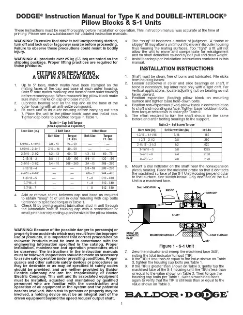
1WARNING: Because of the possible danger to persons(s) or property from accidents which may result from the improper use of products, it is important that correct procedures be followed: Products must be used in accordance with the engineering information specified in the catalog. Proper installation, maintenance and operation procedures must be observed. The instructions in the instruction manuals must be followed. Inspections should be made as necessary to assure safe operation under prevailing conditions. Proper guards and other suitable safety devices or procedures as may be desirable or as may be specified in safety codes should be provided, and are neither provided by Baldor Electric Company nor are the responsibility of Baldor Electric Company. This unit and its associated equipment must be installed, adjusted and maintained by qualified personnel who are familiar with the construction and operation of all equipment in the system and the potential hazards involved. When risk to persons or property may be involved, a holding device must be an integral part of the driven equipment beyond the speed reducer output shaft.DODGE ® Instruction Manual for Type K and DOUBLE-INTERLOCK ®Pillow Blocks & S-1 UnitsThese instructions must be read thoroughly before installation or operation. This instruction manual was accurate at the time of printing. Please see for updated instruction manuals.WARNING: To ensure that drive is not unexpectedly started, turn off and lock out or tag power source before proceeding. Failure to observe these precautions could result in bodily injury.WARNING: All products over 25 kg (55 lbs) are noted on the shipping package. Proper lifting practices are required for those products.FITTING OR REPLACING A UNIT IN A PILLOW BLOCK1. Up to 5” bore, match marks have been stamped on themating faces of the cap and base of each outer housing. Over 5” bore match mark cap and base of each outer housing before removing cap. When reassembling pillow block make sure match marks on cap and base match.2. Lubricate bearing seat on the cap and on the base of theouter housing with an anti-seize compound.3. Fit each unit to its outer housing before carrying out step7. Place the unit in the pillow block base and install cap. Tighten cap bolts to specified torque in Table 1.Table 1 – Cap Bolt Torque (Non-Expansion & Expansion)Bore Size (In.)2 Bolt Base 4 Bolt Base Bolt SizeTorque Ft.-Lbs. Bolt Size Torque Ft.-Lbs. 1-3/16 – 1-11/16 3/8 – 16 24 – 30 — — 1-15/16 – 2-3/16 7/16 – 14 40 – 50 — — 2-7/16 – 2-1/2 1/2 – 13 60 – 75 1/2 – 13 60 – 75 2-15/16 – 3 5/8 – 11 120 – 150 5/8 –11 120 – 150 3-7/16 – 3-1/2 3/4 – 10 208 – 260 3/4 –10 208 – 260 3-15/16 – 4 — — 3/4 – 10 208 – 260 4-7/16 – 4-1/2 — — 7/8 – 9 344 – 430 4-15/16 – 5 — — 1 – 8 512 – 640 5-7/16 – 6 — — 1 – 8 512 - 6406-7/16 – 7——1 - 8512 - 6404. Add or remove shims between cap and base as requiredto obtain “snug” fit of unit in outer housing with cap bolts tightened to specified torque in Table 1.5. Check fit by prying against lubrication stud in unit throughthe lubrication hole in housing cap with a screwdriver or small pinch bar depending upon the size of the pillow blocks.6. The “snug” fit becomes a matter of judgment. A “loose orsloppy” fit may allow a unit mount to move in its outer housing thus wearing the mating surfaces. Too “tight” a fit will not allow the unit to move and compensate for misalignment and for shaft deflection caused by belt pull and dead weight.7. Install bearings per installation instructions contained in thismanual.INSTALLATION INSTRUCTIONS1. Shaft must be clean, free of burrs and lubricated. File nicksfrom housing bases.2. Loosen setscrews in collar and slide bearings on shaft. Ifforce is necessary, tap inner race only with a light drift. For vertical applications, locate adjusting nut on bearing so nut faces upward.3. Position expansion (floating) pillow block on mountingsurface and tighten base hold-down bolts.4. Position non-expansion (fixed) pillow block in correct relationto shaft and mounting surface. Tighten base holddown bolts, then torque setscrews in collar per Table 2.5. The effort required to turn the shaft should be the samebefore and after bolting bearings to the support.Table 2 – Set Screw TorqueBore Size (In)Set Screw Size (In)In-Lbs 1-3/16 – 1-11/165/161651-3/4 – 2-1/23/82902-11/16 – 3-1/21/26203-15/16 – 55/813255-7/16 – 63/421506-7/16 – 77/851306. Mount a dial indicator on the shaft near the nonexpansion(fixed) bearing. Place the indicator probe so that it contacts the machined surface of the S-1 Unit Housing perpendicular to that surface. See sketch below. Only one face of the S-1 Unit is a machined face.Figure 1 - S-1 Unit7. Zero the indicator and sweep the machined face 360°,noting the total indicator turnout (TIR).8. If the TIR is less than or equal to the value shown on Table3, tighten the housing cap bolts per Table 1.9. If the TIR is greater than shown on Table 3, gently tap themachined face of the S-1 housing until the TIR is less than or equal to the value shown on Table 3. Then torque the housing cap bolts per Table 1. Sweep machined faces again to verify that the TIR is still less than or equal to the value shown on Table 3.P .O. Box 2400, Fort Smith, AR 72902-2400 U.S.A., Ph: (1) 479.646.4711, Fax (1) 479.648.5792, International Fax (1) 479.648.5895Dodge Product Support6040 Ponders Court, Greenville, SC 29615-4617 U.S.A., Ph: (1) 864.297.4800, Fax: (1) 864.281.2433All Rights Reserved. Printed in USA.06/15 Litho 20,000© Baldor Electric Company MN3037 (Replaces 499798)*3037-0615*Table 3 – Total Indicator Run-out (TIR)Shaft Size (Inches)TIR (Inches)1-3/16 – 1-7/16 0.00301-1/2 – 1-11/160.00351-3/4 – 2 0.00402-3/16 0.00402-1/4 – 2-1/2 0.00452-11/16 – 3 0.00553-3/16 – 3-1/20.00653-15/16 – 4 0.00704-7/16 – 4-1/2 0.00804-15/16 – 50.008510. The non-expansion (fixed) bearing is now installed. Move tothe expansion (floating) bearing.11. Locate expansion unit in center of its axial travel or atextreme if maximum expansion is required (do not preload stop pin) and torque collar setscrews (52) per Table 2.12. Do not install external grease fittings until completion of finalsteps below.13. Torque setscrews of expansion unit (Table 2).14. Repeat Steps 6, 7, 8 and 9 for the expansion bearing.15. The expansion (floating) bearing is now installed.LUBRICATION GUIDELINESThis bearing is factory lubricated with a lithium or lithium complex base grease which is suitable for most applications. However, extra protection is necessary if the bearing is subjected to excessive moisture, dust, corrosive vapor or other harsh environments. In these cases, the bearing should contain as much grease as speed will permit (a full bearing with consequent slight leakage through the seal is the best protection against contaminant entry).For relubrication, select a grease that is compatible with a lithium or lithium complex grease. The following table is a general guide for normal operating conditions. However, some situations may require a change in lubricating periods as dictated by experience.Normal Operation — This bearing has been greased at the factory and is ready to run. The following table is a general guide for relubrication. However, certain conditions may require a change of lubricating periods as dictated by experience. See “High Speed Operation” and “Operation in Presence of Dust, Water or Corrosive Vapors” above.High Speed Operation — High speed operation is 70% of maximum catalog speed and above. In the higher speed ranges too much grease will cause overheating. The amount of grease that the bearing will take for a particular high speed application can only be determined by experience — see “Operating Temperature” below. If excess grease in the bearing causes overheating, it will be necessary to remove grease fitting (also drain plug when furnished) to permit excess grease to escape. The bearing has been greased at the factory and is ready to run. When establishing a relubrication schedule, note that a small amount of grease at frequent intervals is preferable to a large amount at infrequent intervals.Operation in Presence of Dust, Water or Corrosive Vapors — Under these conditions the bearing should contain as much grease as speed will permit, since a full bearing with consequent slight leakage is the best protection against entrance of foreign material. In the higher speed ranges too much grease will cause overheating — see “High Speed Operation” above. In the lower speed ranges it is advisable to add extra grease to a new bearing before putting into operation. Bearings should be greased as often as necessary (daily if required) to maintain a slight leakage at the seals.Operating Temperature — Abnormal bearing temperature may indicate faulty lubrication. Normal temperature may range from a few degrees up to 100ºF above ambient, depending on bearing size, speed, loading and environmental conditions. Unusually high temperature, in this range, accompanied by excessive leakage of grease indicates too much grease. In the circumstance that there is excess grease in the bearing, remove the grease fitting to allow the excess grease to purge. When purging ceases, wipe excess grease with a clean rag and screw fitting back into the bearing. High temperature with no grease showing at the seals, particularly if the bearing seems noisy, usually indicates too little grease. Normal temperature and a slight showing of grease at the seals indicate proper lubrication.Table 4 – Lubrication Guide Read Preceding Paragraphs Before Establishing Lubrication ScheduleHours Run per Day Suggested Lubrication Period In Weeks 1 to 250RPM 251 to 500RPM 501 to 750RPM 751 to 1000RPM 1001 to 1500RPM 8162412121012751053742521Lubrication recommendations are intended for standard products applied in general operating conditions. For modified products, high temperature environments and other anomalous applications, contact product engineering at 864.284.5700.Kind of Grease — Many ordinary cup greases will disintegrate at speeds far below those at which DODGE bearings will operate successfully if proper grease is used. DODGE bearings have been lubricated at the factory with an NLGI #2 lithium complex base grease. Relubricate with lithium complex-base grease or a grease which is compatible with original lubricant and suitable for roller bearing service. In unusual or doubtful cases the recommendation of a reputable grease manufacturer should be secured.Storage or Special Shutdown — If exposed to wet or dusty conditions or to corrosive vapors, extra protection is necessary. Add grease until it shows at the seals; rotate the bearing to distribute grease; cover the bearing. After storage or idle period, add a little fresh grease before running. During long idle periods, rotate shaft at least once a month.Special Operating Conditions — Refer acid, chemical, extreme or other special operating conditions to Baldor Electric Company.。
产品样本Catalog1TL0001 Low-voltage Three-phase Motor1TL0001低压三相异步电动机2公司概况 Company Profile西门子电机(中国)有限公司是西门子在中国的独资企业,位于江苏省仪征市,占地面积为 200亩。
公司主要致力于研发和生产中小型低压三相异步电动机,目前生产符合 IEC 标准的西门子品牌三相异步电动机、以及按中国标准设计的贝得品牌系列三相异步电动机。
作为西门子在全球中小型低压电机产品的重要生产基地之一,公司坚持秉承西门子 100 多年的电动机设计和生产经验和先进技术,拥有先进的生产设备和生产工艺,采用西门子特色的现代化管理模式,严格按照国际标准 ISO9001:2008 实施全面质量管理,竭诚为广大客户提供优质的产品和服务!西门子电机(中国)有限公司 Siemens Standard Motors Ltd. (SSML)Siemens Standard Motors Ltd. (SSML) is a Siemens-ownedcompany in China. With an area of 200 acres, SSML is located in Yizheng City, Jiangsu Province. The company focuses on developing and producing small and medium low-voltage motors. Currently, SSML mainly produce Siemens brand low voltage AC motors according to IEC standards, and Beide brand low voltage motors designed according to China local standards.As one of Siemens main low-voltage motor production facilities worldwide, SSML uses the knowledge and experience of more than 100 years in motor design and manufacturing, owns the advanced manufacture equipment and process, adopts the SIEMENS modern management model , and implements comprehensive quality control according to ISO9001 2008. SSML will continuously serve customers with high quality products and good service.西门子电机(中国)有限公司3西门子电机(中国)有限公司公司概况Company Profile■ 让顾客满意• 顾客满意是公司发展的基础。
直线电机选型知识点总结一、直线电机的工作原理直线电机是一种利用电磁感应原理实现的线性运动型电机,工作原理和直流电动机相似,但是线性运动的特点使得直线电机具有更广泛的应用领域。
直线电机由定子和活动子两部分组成,通常定子是由线圈组成,而活动子则是由磁铁组成。
当通电时,定子线圈产生磁场,吸引或排斥活动子的磁铁,从而实现线性运动。
二、直线电机的分类1. 电磁直线电机:利用磁铁和电磁感应原理实现线性运动的电机,包括直线同步电机、直线步进电机等。
2. 永磁直线电机:利用永磁体和电流之间的相互作用实现线性运动的电机,包括直线同步永磁电机、直线步进永磁电机等。
3. 超导直线电机:利用超导材料的独特性质实现超导电磁体和磁场之间的相互作用,实现线性运动的电机。
三、直线电机选型的影响因素1. 负载要求:负载要求包括负载力大小、运动速度、加速度等,这些要求将影响直线电机的功率、扭矩和速度等性能参数的选取。
2. 运动模式:直线电机可以实现直线运动、往复运动、多自由度运动等不同的运动模式,根据具体的应用需求选择不同类型的直线电机。
3. 环境条件:包括工作温度、湿度、防尘防水等环境条件,好的直线电机应具有良好的耐高温、防尘防水等性能。
4. 机械结构:机械结构包括导轨、导向装置等,需要考虑直线电机与周围设备的机械匹配性,确保能够实现稳定的运动。
5. 控制系统:控制系统包括控制方式、控制精度、控制算法等,应根据具体应用场景选择合适的控制系统,确保直线电机的准确性和稳定性。
四、直线电机选型的方法1. 根据负载要求选取合适的型号:首先根据负载的大小、运动速度、加速度等要求选取合适的直线电机型号,通常可以通过查阅相关的技术手册或者咨询厂家进行选型。
2. 根据环境条件选取合适的材料和防护措施:根据具体的环境条件选取能够满足要求的材料和防护措施,例如高温工作环境可以选用耐高温材料,防水防尘环境需要选用防护等级较高的直线电机。
3. 根据机械结构进行匹配:根据直线电机与周围设备的机械匹配性进行选型,确保直线电机能够稳定运行。

科尔摩根直接驱动直线电机选型指南带有AKD TM 伺服驱动系统尔2K O LLM O R G E N 科摩根3目录直接驱动直线(DDL )电机4AKD ™伺服驱动 10 联合研发能力 14 直接驱动直线电机综述 15 无铁芯 - 非冷却型DDL 的数据和尺寸IL06 系列 18 IL12 系列 20 IL18 系列 22IL24 系列 26无铁芯磁路 28 有铁芯DDL 的数据和尺寸ICD05 系列 32ICD10 系列 34ICD 磁路 36 有铁芯- 非冷却型DDL 的数据和尺寸IC11 系列 40 IC22 系列 42 IC33 系列 46IC44 系列 50 有铁芯- 水冷型DDL 的数据和尺寸IC11 系列 54 IC22 系列 56 IC33 系列 60IC44 系列 64有铁芯磁路 68 连线和输出 70高柔性电缆组 72 应用选型 74 型号命名规则 78MOTIONEERING ® 应用引擎81科尔摩根直接驱动直线电机选型指南克服设计、采购和时间障碍科尔摩根很清楚:如果能够帮助原始设备制造商的工程师克服遇到的障碍,就可以显著提高其工作成效。
因而,我们主要通过如下三种方式来帮助他们:集成标准和定制产品在很多情况下,最佳方案都不是一成不变的。
我们拥有专业应用知识,可以根据全面的产品组合来修改标准产品或开放全定制解决方案,从而为设计奠定良好的基础。
提供运动解决方案而不仅仅是部件在各公司减少供应商数量和工程人力的过程中,他们需要一家能够提供多种集成解决方案的全系统供应商。
科尔摩根就采用了全面响应模式,为客户提供全套解决方案,这些方案将编程软件、工程服务以及同类最佳的运动部件结合起来。
覆盖全球我们在北美、欧洲、中东和亚洲拥有众多直销、工程支持团队,制造工厂以及分销商,并且临近全球各地的原始设备制造商。
这种便利优势可以加速我们的供货过程,根据客户需要随时随地供货。
财务和运营稳定性科尔摩根的母公司是价值130亿美元的丹纳赫集团。
直线电机选型要求准则:直线电机:①峰值推力不小于计算峰值推力;②连续推力不小于计算连续推力
1、直线电机的分类
单轴模组、龙门直线模组、XY直线模组、流水线直线电机、标机设备直线模组直线电机系统配套及选型
1、直线电机的选型要求
如何确定系统能达到最大的速度或者加速度?
选型要求准则:
直线电机:①峰值推力不小于计算峰值推力;
②连续推力不小于计算连续推力;
③计入20%裕度,电机推力要大于或等于1.2计算推力;
承载能力:①(有铁芯电机要考虑直线导轨有足够承载电磁吸力的能力);
②精度等级
③品牌选择(HIWIN、CPC、PIM),一般应用场景
(THK、IKO、INA),高精密应用场景
光栅方面:①光栅尺栅距;
②分辨率;
③最大允许速度=分辨率*采样频率;
④厂家选择:雷尼绍、海德汉、Microe;
驱动器方面:峰值电流大于或等于直线电机峰值电流;
连续电流大于或等于直线电机峰值电流;
母线电压Ubus=VMax Ke+IpR
2、直线电机的计算选型
1、系统运动参数的技术要求
行程:总行程、加减速行程、匀速行程;
运动时间:加速时间Ta,匀速时间Tr,减速时间Td,停歇时间Tdw、运动周期T
运动质量:有效负责、平台质量、动子质量;
运动速度:最大速度;。

产品分类A、同步带直线模组特点:根据客户需要定制长度,模组总长可达6米;可承载5kg-35kg不等;重复定位精度<=0.05mm。
注:模组总长=有效行程+(250mm~400mm不等)1.W45A-05直线模组截面:45*40mm行程:50~3850mm直度:<=0.03/300mm弯扭:<=0.03/300mm承载:0~50N扭矩:0~3N.M2.W40-10直线模组截面:40*40mm行程:50~3850mm直度:<=0.03/300mm弯扭:<=0.03/300mm承载:0~100N扭矩:0~3N.M3.W45-15直线模组截面:45*45mm行程:50~5850mm直度:<=0.03/300mm弯扭:<=0.03/300mm承载:0~150N扭矩:0~3N.M4.W50-25直线模组截面:50*50mm行程:50~5850mm直度:<=0.03/300mm弯扭:<=0.03/300mm承载:0~200N扭矩:0~4N.M5.W60-35直线模组截面:60*55mm行程:50~5850mm直度:<=0.03/300mm弯扭:<=0.03/300mm承载:0~300N扭矩:0~4N.MB、丝杆模组共1个系列,3种型号特点:固定长度;承载5kg;重复定位精度<=0.02mm;导程:2.5mm;适用42步进电机1.S35-50直线模组截面:38*23mm行程:50mm直度:<=0.03/300mm弯扭:<=0.03/300mm承载:0-50N扭矩:0~1N.M2.S35-100直线模组截面:38*23mm行程:100mm直度:<=0.03/300mm弯扭:<=0.03/300mm承载:0-50N扭矩:0~1N.M3.S35-150直线模组截面:38*23mm行程:150mm直度:<=0.03/300mm弯扭:<=0.03/300mm承载:0-50N扭矩:0~1N.M直线模组常见结构及配置示例1:一维单支单滑块直线模组CCM直线模组*1支XY连接件(地脚)*2个直连模式:电机笼/板*1个,联轴器*1个或(变速模式:变速板*1个,变速轮套件1*套)-------------------------------------------------------------------------------------------------------------2:一维单支双滑块直线模组CCM直线模组*1支附加滑块*1个XY连接件(地脚)*2个直连模式:电机笼/板*1个,联轴器*1个或(变速模式:变速板*1个,变速轮套件1*套)-------------------------------------------------------------------------------------------------------------3:一维双轨同步结构CCM直线模组*2支XY连接件(地脚)*4个直径12mm传动轴*1个联轴器12-12*2个直连模式:电机笼/板*1个,联轴器*1个或(变速模式:变速板*1个,变速轮套件1*套)-------------------------------------------------------------------------------------------------------------4:一维双轨双滑块同步结构CCM直线模组*2支XY连接件(地脚)*4个直径12mm传动轴*1个联轴器12-12*2个附加滑块*2个直连模式:电机笼/板*1个,联轴器*1个或(变速模式:变速板*1个,变速轮套件1*套)------------------------------------------------------------------------------------------------------------5:一维双轨并立结构CCM直线模组*2支XY连接件(地脚)*4个联轴器12-12*2个直连模式:电机笼/板*1个,联轴器*1个或(变速模式:变速板*1个,变速轮套件1*套)-------------------------------------------------------------------------------------------------------------6:二维XY十字卧式结构CCM直线模组*2支T型连接件*1个XY连接件(地脚)*2个直连模式:电机笼/板*2个,联轴器*2个或(变速模式:变速板*2个,变速轮套件2*套)-------------------------------------------------------------------------------------------------------------7:二维XY十字侧立结构CCM直线模组*2支L连接板*1个XY连接件(地脚)*2个直连模式:电机笼/板*2个,联轴器*2个或(变速模式:变速板*2个,变速轮套件2*套)-------------------------------------------------------------------------------------------------------------8:二维XY工字卧式结构CCM直线模组*3支直径12mm传动轴*1个T型连接件*2个XY连接件(地脚)*4个联轴器12-12*2个直连模式:电机笼/板*2个,联轴器*2个或(变速模式:变速板*2个,变速轮套件2*套)-------------------------------------------------------------------------------------------------------------9:二维XY工字X轴双滑块结构CCM直线模组*3支直径12mm传动轴*1个T型连接件*2个XY连接件(地脚)*4个附加滑块*1个联轴器12-12*2个直连模式:电机笼/板*2个,联轴器*2个或(变速模式:变速板*2个,变速轮套件2*套)-------------------------------------------------------------------------------------------------------------10:二维XY工字侧立结构CCM直线模组*3支直径12mm传动轴*1个XY连接件(地脚)*4个L连接板*2个联轴器12-12*2个直连模式:电机笼/板*2个,联轴器*2个或(变速模式:变速板*2个,变速轮套件2*套)-------------------------------------------------------------------------------------------------------------11:三维XYZ同步带侧立结构CCM直线模组*4支直径12mm传动轴*1个XY连接件(地脚)*4个T型连接件*1个L型连接件*2个联轴器12-12*2个直连模式:电机笼/板*3个,联轴器*3个或(变速模式:变速板*3个,变速轮套件3*套)-------------------------------------------------------------------------------------------------------------XY连接件(地脚)*4个T型连接板*2个联轴器12-12*2个直连模式:电机笼/板*2个,联轴器*2个或(变速模式:变速板*2个,变速轮套件2*套)-------------------------------------------------------------------------------------------------------------13:二维XYY干字侧立结构CCM直线模组*3支XY连接件(地脚)*4个L型连接板*2个联轴器12-12*1个直连模式:电机笼/板*2个,联轴器*2个或(变速模式:变速板*2个,变速轮套件2*套)-------------------------------------------------------------------------------------------------------------14:三维干字侧立悬臂Z轴CCM直线模组*4支XY连接件(地脚)*4个T型连接件*1个L型连接件*2个联轴器12-12*1个直连模式:电机笼/板*3个,联轴器*3个或(变速模式:变速板*3个,变速轮套件3*套)-------------------------------------------------------------------------------------------------------------15:二维XYY中字卧式结构CCM直线模组*3支XY连接件(地脚)*4个T型连接板*2个直径12mm传动轴*2个联轴器12-12*4个直连模式:电机笼/板*2个,联轴器*2个或(变速模式:变速板*2个,变速轮套件2*套)-------------------------------------------------------------------------------------------------------------XY连接件(地脚)*4个直径12mm传动轴*2个L型连接板*2个联轴器12-12*4个直连模式:电机笼/板*2个,联轴器*2个或(变速模式:变速板*2个,变速轮套件2*套)-------------------------------------------------------------------------------------------------------------17:XZ轴X轴悬臂结构CCM直线模组*2支XY连接件(地脚)*2个附加滑块*1个三角架1*个直连模式:电机笼/板*2个,联轴器*2个或(变速模式:变速板*2个,变速轮套件2*套)-------------------------------------------------------------------------------------------------------------18:二维井字结构CCM直线模组*4支附加滑块*2个XY连接件(地脚)*4个T型连接板(地脚)*4个直径12mm传动轴*2个联轴器12-12*4个直连模式:电机笼/板*2个,联轴器*2个或(变速模式:变速板*2个,变速轮套件2*套)-------------------------------------------------------------------------------------------------------------19:二维井字双滑块结构CCM直线模组*4支XY连接件(地脚)*4个T型连接板(地脚)*4个附加滑块*4个直径12mm传动轴*2个联轴器12-12*4个直连模式:电机笼/板*2个,联轴器*2个或(变速模式:变速板*2个,变速轮套件2*套)-------------------------------------------------------------------------------------------------------------20:三维单X轴双Y轴双Z轴结构CCM直线模组*5支直径12mm传动轴*2个XY连接件(地脚)*4个T型连接件*2个附加滑块*2个三角架*2个联轴器12-12*4个直连模式:电机笼/板*3个,联轴器*3个或(变速模式:变速板*3个,变速轮套件3*套)-------------------------------------------------------------------------------------------------------------21:三维双X轴双Y轴单Z轴结构CCM直线模组*5支直径12mm传动轴*1个XY连接件(地脚)*4个T连接件*2个附加滑块*2个三角架*2个联轴器12-12*4个直连模式:电机笼/板*3个,联轴器*3个或(变速模式:变速板*3个,变速轮套件3*套)-------------------------------------------------------------------------------------------------------------22:三维单X轴双Y轴单Z轴结构CCM直线模组*4支直径12mm传动轴*1个XY连接件(地脚)*4个T型连接件*1个附加滑块*2个三角架*2个联轴器12-12*2个直连模式:电机笼/板*3个,联轴器*3个或(变速模式:变速板*3个,变速轮套件3*套)-------------------------------------------------------------------------------------------------------------23:三维单X轴双Y轴单Z轴结构CCM直线模组*3支直径12mm传动轴*1个XY连接件(地脚)*4个附加滑块*2个三角架*2个联轴器12-12*2个直连模式:电机笼/板*2个,联轴器*2个或(变速模式:变速板*3个,变速轮套件3*套)-------------------------------------------------------------------------------------------------------------24:三维XYZ丝杆侧立结构CCM直线模组*3支S35丝杆模组*1支直径12mm传动轴*1个XY连接件(地脚)*4个L型连接件*2个联轴器12-12*2个S35固定座(可连W40-10\W45-15\W50-20)*1个直连模式:电机笼/板*3个,联轴器*3个或(变速模式:变速板*3个,变速轮套件3*套)-------------------------------------------------------------------------------------------------------------25:三维XYZ铝材支架结构CCM直线模组*3支定制小T型连接件*4个T型连接件*1个铝材支架*1个直连模式:电机笼/板*3个,联轴器*3个或(变速模式:变速板*3个,变速轮套件3*套)-------------------------------------------------------------------------------------------------------------26:三维XY双Z轴铝材支架结构CCM标准模组*4支特定小T连接件*2个T型连接件*2个侧面支撑板*12个联轴器12-12*2个直径12mm传动轴*1铝材支架*1个直连模式:电机笼/板*3个,联轴器*3个或(变速模式:变速板*3个,变速轮套件3*套)命名规则出轴形式电机区位。
—Baldor-Reliance® motorsFor farm, agriculture and grain handlingBaldor-Reliance premium motors for farm, agriculture and grain applications are built to perform in demanding outdoor environments. Designed with features for rugged conditions, these locally made motors provide reliabilityto keep your operations up and running.Over 90% of Baldor-Reliance motors meet the Buy-AmericanAct. Find out more here.Centrifugal fans3 – 50 Hp (2.2 - 37 kW)• Shaft length 1” longer than NEMA standard • Lubed for life double sealed ball bearings• Lip seal and v-ring slinger on DE for increased moisture resistance• Screens on ODP to protect against trash and debris Grain dryer centrifugal fan motors are available in ODP and TEFC, single and three-phase designs. Ideal for high-pressure grain drying and farm building fans.Vane axial fans1.5 – 15 Hp (1.12 - 11.2 kW)• Shaft length is 3/4” longer than NEMA standard • 1/4 – 20 tapped and keyed shaft• Convenient lead location for ease of conduit connectivity• Normally closed winding thermostats to protect against overheating• Lubed for life double sealed ball bearings on TEAO motors• Lip seal and v-ring slinger on DE for increase moisture resistance on TEAO motorsVain axial fan grain dryer motors come in OPAO and TEAO, single and three-phase designs and are used for crop dryers.Universal crop dryer5 – 15 Hp (3.7 - 11.2 kW)• Shaft length is 3/4” longer than NEMA standard • 1/4 – 20 tapped and keyed shaft• Convenient lead location for ease of conduit connectivity• Switchless design for increased reliability • Lubed for life double sealed ball bearing• Normally closed winding thermostats to protect against overheatingSingle phase permanent split capacitor (switchless) designavailable in Open Air Over (OPAO) for vane axial fan crop dryersAeration fan motorsSingle phase• 1/2 – 3 Hp (.37 - 2.2 kW)Three phase• 3/4 – 3 Hp (.56 - 2.2 kW)• 1/4 – 20 tapped and keyed shaft• Terminal panel for ease of connectivity• Automatic thermal overload protection (single phase)• Normally closed winding thermostats to protect against overheating (three phase)• Lubed for life double shielded ball bearingsAeration fan, single and three-phase, TEAO, foot mounted. Ideal for aeration fans, exhaust fans and air handling systems usedthroughout grain facilities.DE= Drive End ODE = Opposite Drive EndGeneral farm/agriculture motorsDairy/vacuum pump motor7-1/2 – 10 Hp (5.6 - 7.5 kW)• Gasketed manual reset thermal overload protection • Oversized conduit/capacitor box for ease of connectivity• Aluminum heat sync fan on DE for increased bearing life• 50° C ambient-continuous duty.These vacuum pump motorscontain all the necessary thermal protection to extend drive end bearing life and overall system reliability.(PSC) direct drive fan motor1/4 – 1 Hp (.2 - .75 kW)• Switchless design for increased reliability • 1” extended through bolts for grille mounting • Terminal panel for ease of connectivity • Automatic thermal overload protection • Lubed for life double shielded ball bearings These (PSC), or permanent split capacitor motors are used for commercial duty wall-mounted fans, used in confinement houses, exhaust fans and unit heaters.Yoke/pedestal fan1/4 – 1/2 Hp (2 - .37 kW)• Robust stamped steel pedestal mount• 1" extended through-bolts for grille mounting • Terminal panel for ease of connectivity • Automatic thermal overload protection • Lubed for life double shielded bearings • Switchless design for increased reliabilityDesigned to meet manufacturers requirements for air circulators where the permanent splitcapacitor motor is mounted directly to the fan column. For direct drive exhaust and vent fans in HVAC and poultry. Designed for continuous air-over applications.Incubator/hatchery vent fan motors1/3 Hp (.25 kW)• Normally closed winding thermostats to protect against overheating• 1” extended through bolts for grille mounting • Terminal panel for ease of connectivity • Pilot circuit to facilitate system protection• Flat slinger on DE for improved moisture protection • Lubed for life double shielded ball bearingsIncubator/hatchery vent fan, single phase, TEAO. Also used for HVAC condensers and grille mount vent fan applicationsInstant reversing motors1/3 – 1 Hp (.25 - .75 kW)• High starting torque• Electrically designed for optimal performance in instant reversing applications• Gasketed manual reset thermal overload protection • Lubed for life double shielded ball bearings Instant reversing, single phase, TEFC, foot mounted. Commonapplications include barn cleaners, bulk feeders and other industrial applications.Irrigation tower drives3/4 – 2 Hp (.56 - 1.5)• Sealed fit at endplate • Sheds water• Conduit box is cast into the ODE endplate • High overload capabilities • 50/60HzIrrigation tower drive motors. Three-phase, totally enclosed non ventilated (TENV).ABB Ability TMSmart Sensor for motors(for non-hazardous areas)• Motor smart sensor with 2 year subscription andmounting hardware for either finned/rib cooled orrolled steel motors.The ABB Ability Smart Sensorconverts traditional motors intosmart, wirelessly connecteddevices. It enables users to monitorthe health of their motors andto plan maintenance in advance.Unplanned downtime can beavoided, efficiency optimized andsafety improved.ABB AbilitySmart Sensor for motors(for hazardous areas)• 1 year, 2 year or 5 year subscription• Motor smart sensor for hazardous areas with aluminum bracket mounting tool for ribbed cooled or finned motors• Motor smart sensor for hazardous locations with flat mounting tool for rolled steel motors/motors-generators—ABB Motors and Mechanical Inc.5711 R.S. Boreham, Jr. Street Fort Smith, AR 72901Ph: 1.479.646.47119A K K 108391 07.2021 P r i n t s h o p 100。
美国葆德Baldor各种电机的工作原理及应用一、伺服电动机伺服电动机广泛应用于各种控制系统中,能将输入的电压信号转换为电机轴上的机械输出量,拖动被控制元件,从而达到控制目的。
伺服电动机有直流和交流之分:早的伺服电动机是一般的直流电动机,在控制精度不高的情况下,才采用一般的直流电机做伺服电动机。
目前的直流伺服电动机从结构上讲,就是小功率的直流电动机,其励磁多采用电枢控制和磁场控制,但通常采用电枢控制。
直流伺服电动机在机械特性上能够很好的满足控制系统的要求,但是由于换向器的存在,存在以下不足:换向器与电刷之间易产生火花,干扰驱动器工作,不能应用在有可燃气体的场合电刷和换向器存在摩擦,会产生较大的死区结构复杂,维护比较困难交流伺服电动机本质上是一种两相异步电动机,其控制方法主要有三种:幅值控制、相位控制和幅相控制。
一般地,伺服电动机要求电动机的转速要受所加电压信号的控制;转速能够随着所加电压信号的变化而连续变化;电动机的反映要快、体积要小、控制功率要小。
二、步进电动机所谓步进电动机就是一种将电脉冲转化为角位移的执行机构。
更通俗一点讲:当步进驱动器接收到一个脉冲信号,它就驱动步进电机按设定的方向转动一个固定的角度。
我们可以通过控制脉冲的个数来控制电机的角位移量,从而达到定位的目的;同时还可以通过控制脉冲频率来控制电动机转动的速度和加速度,从而达到调速的目的。
目前,比较常用的步进电动机包括反应式步进电动机(VR)、永磁式步进电动机(PM)、混合式步进电动机(HB)和单相式步进电动机等。
步进电动机和普通电动机的区别主要就在于其脉冲驱动的形式,正是这个特点,步进电动机可以和现代的数字控制技术相结合。
但步进电动机在控制精度、速度变化范围、低速性能方面都不如传统闭环控制的直流伺服电动机;所以主要应用在精度要求不是特别高的场合。
由于步进电动机具有结构简单、可靠性高和成本低的特点,所以步进电动机广泛应用在生产实践的各个领域;尤其是在数控机床制造领域,由于步进电动机不需要A/D 转换,能够直接将数字脉冲信号转化成为角位移,所以一直被认为是理想的数控机床执行元件。