威德福卧式移动上扣机
- 格式:pdf
- 大小:2.20 MB
- 文档页数:27
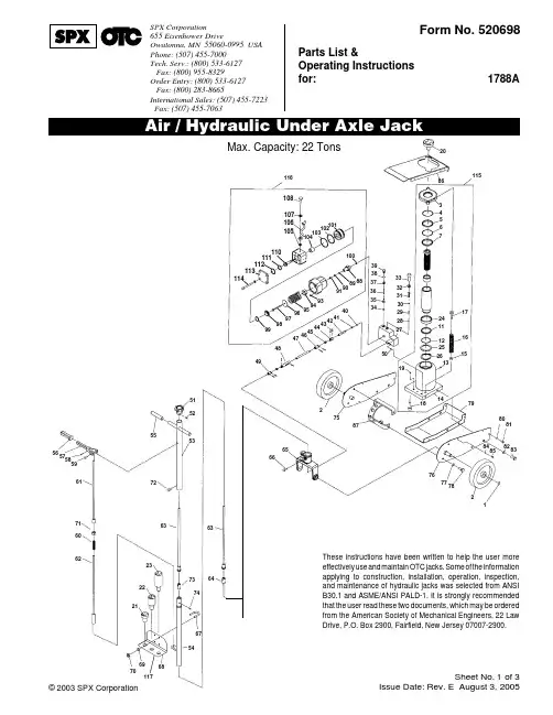
Sheet No. of 3Issue Date: Rev. E August 3, 2005© 2003 SPX CorporationForm No. 520698Parts List &Operating Instructions for:1788A1SPX Corporation655 Eisenhower DriveOwatonna, MN 55060-0995 USA Phone: (507) 455-7000Tech. Serv.: (800) 533-6127 Fax: (800) 955-8329Order Entry: (800) 533-6127 Fax: (800) 283-8665International Sales: (507) 455-7223 Fax: (507) 455-7063Max. Capacity: 22 Tons636451525355565758596171606272632322217374675411610810710610510410310210111011111211311410040899091939495969798998841424344454647484939383736353450272829303132332086115345672411122526151617131418192758765667980818283848576777821686970117These instructions have been written to help the user more effectively use and maintain OTC jacks. Some of the information applying to construction, installation, operation, inspection,and maintenance of hydraulic jacks was selected from ANSI B30.1 and ASME/ANSI PALD-1. It is strongly recommended that the user read these two documents, which may be ordered from the American Society of Mechanical Engineers, 22 Law Drive, P.O. Box 2900, Fairfield, New Jersey 07007-2900.Parts List & Operating Instructions Form No. 520698, Sheet 1 of 3, back Item No.Qty.Description12Snap Ring22Wheel31Spring Hanger41Snap Ring51Bushing61O-ring71Bushing111Washer121O-ring131Oil Filler Plug141Oil Cylinder Assembly152Nut162Spring172Bolt183Bolt193O-ring20120 mm Extension Adapter 21120 mm Extension Adapter 22160 mm Extension Adapter 231100 mm Extension Adapter 241Piston Ring251Washer261Snap Ring271Valve Block281Steel Ball291Pin301Steel Ball311Spring321Copper Washer331Bolt341Steel Ball351Ball Seat361Spring371Screw381Sealing Washer391Valve Plug Screw401Steel Ball411Sealing Washer421Release Valve Rod438Rivet441Universal Joint A452Block461Universal Joint B471Rod481Universal Joint C491Universal Joint D501Pin511Knob521Pin531Rear Handle541Front Handle552Handle Sleeve561Sleeve571Lock Lever581Pin592Bolt601Spring611Control Rod A621Control Rod B632Convey Rod641Rod Joint651Handle Socket661Bolt672U-bolt681Fix Board694Spring Washer704Nut711Nut721Screw731Rod Joint741Pin751Frame Left761Frame Right774Washer784Bolt791Bed804Washer814Bolt824Washer834Bolt844Washer854Bolt861Cover Board871Bracket881Cylinder Pump891Y-Sealing Washer901Nylon Washer911Copper Washer931O-ring941Hex Nut951Spring961Washer971Pump Plunger981Washer991O-ring1001Copper Washer1011Piston1021O-ring1031O-ring1041Sealing Washer1051Copper Joint Ring1061Air Hose (with Air Valve) 1071Washer1081Bolt1101Release Air Rod1111O-ring1121O-ring1131Cylinder Cover1144Bolt1151Power Unit Assembly 1161Air Pump Assembly 1173Hairpin ClipItem No.Qty.DescriptionSheet No. of 3Issue Date: Rev. E August 3, 2005© 2003 SPX CorporationItemNo.Qty.DescriptionItemNo.Qty.DescriptionAdapter 1 — No. 520712:201Extension Adapter(20 mm x 68.5 mm dia.)1171Hairpin ClipAdapter 2 — No. 520713:211Extension Adapter(20 mm x 48 mm dia.)1171Hairpin ClipAdapter 3 — No. 520714:221Extension Adapter(60 mm x 48 mm dia.)1171Hairpin ClipAdapter 4 — No. 520715:231Extension Adapter(100 mm x 48 mm dia.)1171Hairpin Clip Adapter Rack Assembly No. 520711:672U-bolt 681Fix Board694Spring Washer 704NutAir Block Assembly No. 520708:183Bolt 193O-ring271Valve Block 281Steel Ball 291Pin301Steel Ball 311Spring321Copper Washer 331Bolt341Steel Ball 351Ball Seat 361Spring 371Screw381Sealing Washer 391Valve Plug Screw 501PinAir Hose Kit No. 520703:1051Copper Joint Ring 1061Air Hose (w/ air valve)1071Washer 1081BoltAir Pump Hardware No. 520730:881Cylinder Pump 941Hex Nut 951Spring 961Washer971Pump Plunger 1011Piston1101Release Air Rod 1131Cylinder Cover 1144BoltAir Pump Kit No. 520702:1161Air Pump Assembly Air Seal Kit No. 520700:891Y-sealing Washer 901Nylon Washer 911Copper Washer 931O-ring 981Washer 991O-ring1001Copper Washer 1021O-ring 1031O-ring1041Sealing Washer 1051Copper Joint Ring 1111O-ring 1121O-ring Frame Kit No. 521987:751Frame Left 761Frame Right 871Bracket Handle Kit No. 520704:511Knob 521Pin531Rear Handle 541Front Handle 552Handle Sleeve 561Sleeve 571Lock Lever 581Pin 592Bolt 601Spring611Control Rod A 621Control Rod B 632Convey Rod 641Rod Joint 711Nut 721Screw 731Rod Joint 741PinHandle Pivot Kit No. 520706:651Handle Socket Handle Retaining Screw No. 520710:661Bolt Hardware Kit No. 521988:774Washer 784Bolt 804Washer 814Bolt 824Washer 834Bolt 844Washer 854BoltItemNo.Qty.DescriptionHydraulic Seal Kit No. 520699:41Snap Ring 51Bushing 61O-ring 71Bushing 111Washer 121O-ring131Oil Filler Plug 193O-ring241Piston Ring 251Washer 261Snap RingHydraulic Unit Kit No. 520701:824Washer 834Bolt1151Power Unit Assembly Inspection Plate No. 520729:844Washer 854Bolt861Cover Board Release Screw Assembly No. 520707:401Steel Ball411Sealing Washer 421Release Valve Rod 438Rivet441Universal Joint A 452Block461Universal Joint B 471Rod481Universal Joint C 491Universal Joint D 501PinReturn Spring Assembly No. 520709:31Spring Hanger 152Nut 162Spring 172Bolt Skid Plate No. 520827:791Bed 804Washer 814Bolt Wheel Kit No. 520705:11Snap Ring 21Wheel2Parts List & Operating InstructionsForm No. 520698U-boltSpring,Washers,& NutslAdapter HolderFigure 1setting up a job.•Read, understand, and follow safety precautions and operating instructions. If the operator cannot read these instructions, operating instructions and safety precautions must be read and discussed in the operator’s native language.•Wear eye protection that meets the requirements of ANSI Z87.1 and OSHA.•Inspect the jack before each use; do not use the jack if it is damaged, altered, or in poor condition.•To prevent tipping, set up the jack on a hard, level surface.•The load must not exceed the rated lifting capacity of the jack. Lift only dead weight.•Center the load on the jack saddle; off-center loads can damage the seals and cause hydraulic failure.•Use the jack for lifting purposes only. This jack is designed to LIFT loads, not support loads. Immediately support a lifted load with jack stands.•Stay clear of lifted loads.•The safety valve is set at the factory; no further adjustment is needed.•Use only approved hydraulic fluid, such as Chevron AW Hydraulic Oil MV or equivalent.Setup Instructions1.Add 1/2 oz. clean lubricating oil to the air inlet, and connect the air supply. IMPORTANT: To prevent damage to the air pump, the air supply must be clean and dry.2.Assemble the adapter holder to the handle using U-bolts, nuts, and spring washers provided. See Figure 1.NOTE: When not using the adapters, store them on the holder. Lock each adapter in place with a hitch pin.Parts List & Operating Instructions Form No. 520698, Sheet 2 of 3, backOperating Instructions1.Tightly close the release valve knob (located on top of the “T” handle) by turning it clockwise.2.Center the load on the jack saddle. Connect the air supply, and squeeze the air valve lever to raise the load.Release the air valve lever to stop movement.3.Transfer the load to support stands.4.To lower the jack, open the release valve knob by SLOWLY turning it counterclockwise.NOTE: To adjust the handle, pull up and then release the lever to lock it in one of three positions.Bleeding the JackAir bubbles can become trapped inside the hydraulic system, reducing the efficiency of the jack. Purge air from the system as needed by following these steps:1.With the jack sitting on its base and the ram retracted, bleed air by opening the release valve.2.Pump for 10 seconds.Sheet No. of 3Issue Date: Rev. E August 3, 2005© 2003 SPX CorporationHex Socket BoltRelease ValveFigure 2IMPORTANT: Dirt is the greatest single cause of failure in hydraulic units. Keep the jack clean and well lubricated to prevent foreign matter from entering the system. If the jack has been exposed to rain, snow, sand, or grit, it must be cleaned before it is used.1.When the jack is not in use, keep the piston and pump rods fully retracted. Store the jack on its base and in a well protected area where it will not be exposed to corrosive vapors, abrasive dust, or any other harmful elements.2.Maintain the oil level. If it’s necessary to add oil, remove the filler plug, and fill the reservoir with Chevron AW Hydraulic Oil MV or equivalent.3.Visually inspect the jack before each use. Take corrective action if any of the following problems are found:a.Cracked or damaged housing e.Incorrectly functioning swivel heads or adj. screw b.Excessive wear, bending, or other damage f.Loose hardware c.Leaking hydraulic fluid g.Modified or altered equipment d.Scored or damaged piston rod3Parts List & Operating InstructionsForm No. 520698Pump Prime InstructionsThe air/hydraulic pump may lose its prime during shipment or after long periods without use. To prime the pump, follow these steps:1.Remove the upper cover.2.Loosen the hex socket bolt one-half turn. See Figure 2.3.Close the release valve.4.Operate the air pump while repeatedly tightening and loosening the bolt.5.When the piston begins to rise, tighten the bolt. Verify the piston can rise to the maximum height position.TroubleCauseSolutionErratic Action1. Air in system1. With jack sitting on its base and ram retracted,bleed air by opening release valve. Pump 10 seconds.2. Viscosity of oil too high 2. Change to a lower viscosity oil.3. Ram sticking or binding 3. Look for dirt, gummy deposits, leaks, misalignment,worn parts, or defective packings.4. Internal leakage in ram4. Replace worn packings. Look for excessive contamination or wear.Ram does not advance1. Release valve is open 1. Close release valve located on top of “T” handle.2. Low/no oil in reservoir 2. Fill with oil & bleed system.3. Air locked system3. With jack sitting on its base and ram retracted,open release valve, run pump for 10 seconds.4. Load is above capacity of system 4. Use correct equipment.5.Pump lost its prime 5.Follow “Pump Prime Instructions.”Ram only extends partially1. Low oil level in reservoir 1. Fill reservoir with oil; bleed system.2. Piston rod is binding2. Look for dirt, gummy deposits, leaks, misalignment,worn parts, or defective packings.Ram advances slowly1. Low air pressure1. Adjust air pressure to 90–145 psi.2. Pump not working correctly 2. Rework pump.3. Leaking seals3. Replace seals.Ram advances but doesn’t 1. Release valve is open 1. Close release valve located on top of T” handle.hold pressure2. Ram seals are leaking2. Replace seals.3. Pump check valve not working3. Clean / replace check valve.4. Overload valve leaking / not adjusted 4. Replace / adjust overload valve.Jack leaks oil1. Worn or damaged seals 1. Replace seals.Ram will not retract, or 1. Release valve is closed 1. Open release valve.retracts slowly2. Reservoir too full2. Drain oil to correct level.3. Ram damaged internally3. Take jack to authorized service center for repair.Repairs must be performed in a dirt-free environment by qualified personnel who are familiar with this equipment.。
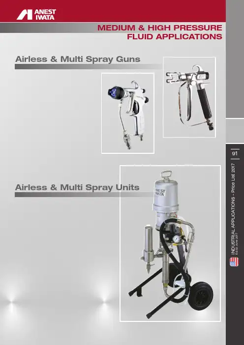
MEDIUM & HIGH PRESSUREFLUID APPLICATIONS Airless & Multi Spray GunsAirless & Multi Spray Units$6.0023.0011/16" 35.00 NOZZLE GLAND SET UNIVERSAL11/16"161.00Ref.Code Description 893501190NEEDLE SPRING 993502190NEEDLE SPRING SEAT 1093529180PACKING 1193841170FILTER 100 MeshPRE-ATOMIZED REVERSIBLE & FLAT AIRLESS TIPS94I N D U S T R I A L A P P L I C A T I O N S - P r i c e L i s t 2017E d .02 J u n e 2017MULTI SPRAY SERIESMSGS-200 120S / 120L / 250S / 250LMSGS-200250LMSGS-200250SMSGS-200120LMSGS-200120SMULTI SPRAY SERIES°Ø inchPump - PP1251CALS-333 CALS-423 TXALS-433 C | ALS-433 TXPump - PP4231NEPump - PP4301CPump - PP4301CNEACCESSORIES99I N D U S T R I A L A P P L I C A T I O N S - P r i c e L i s t 2017E d .02 J u n e 2017Ref.Code DescriptionALS-333 C ALS-423 TXALS-433 CALS-433 TX$4304001160SPACER13.004404443100V PACKING MALE UPPER ADAPTOR X25.00440231005000V PACKING MALE UPPER ADAPTOR X24.004404443150V PACKING MALE UPPER ADAPTOR X23.004404000800V PACKING MALE UPPER ADAPTOR X27.00440444320000V PACKING MALE UPPER ADAPTOR 21.00450443011000CONNECTING ROD X24.00450231022001CONNECTING ROD XX27.00450443016000CONNECTING ROD X24.00460493210000UPPER V PACKING SET 4 pcs./1pk.X23.00460494231100UPPER V PACKING SET 4 pcs./1pk.X32.00460494015000UPPER V PACKING SET 4 pcs./1pk.XX 41.00460494020000UPPER V PACKING SET 4 pcs./1pk.37.00470448310100SUCTION MAIN BODY X98.00470231008001SUCTION MAIN BODY XX 150.00470448315100SUCTION MAIN BODY X106.00470448320200SUCTION MAIN BODY 142.0048UL300802SPRING WASHER X X X X 2.0049UL300703HEXAGON NUT X X XX 2.005094445110NUT X41.00500231020000NUT X14.005094414150NUT X55.005004000790NUT X62.00500444520000NUT21.005104443110V PACKING MALE LOWER ADAPTOR X10.00510231019000V PACKING MALE LOWER ADAPTOR X22.005194443161V PACKING MALE LOWER ADAPTOR X21.005104001800V PACKING MALE LOWER ADAPTOR X24.00510444321100V PACKING MALE LOWER ADAPTOR 21.005204402110LOWER DISTANCE RING X13.00520231010000LOWER DISTANCE RING X10.005204400160LOWER DISTANCE RING X13.00520400016000LOWER DISTANCE RINGX14.005304441110V PACKING FEMALE LOWER ADAPTOR X20.00530231017000V PACKING FEMALE LOWER ADAPTOR X19.005304441160V PACKING FEMALE LOWER ADAPTOR X18.005304005790V PACKING FEMALE LOWER ADAPTOR X24.00530444121100V PACKING FEMALE LOWER ADAPTOR 22.00540493010000LOWER V PACKING SET 4 pcs./1pk.X19.00540494231200LOWER V PACKING SET 4 pcs./1pk.X32.00540494215000LOWER V PACKING SET 4 pcs./1pk.XX30.00540494220000LOWER V PACKING SET 4 pcs./1pk.37.005596662025BALL XX6.005506662040BALL X10.005506662026BALLX6.005604461100VALVE HOLDER SET X258.00560231029001VALVE HOLDER SET X219.005604460160VALVE HOLDER SET X272.00560446017100VALVE HOLDER SET X219.00560446120000VALVE HOLDER SET 90.005794447600UPPER PACKING X11.00570231007000UPPER PACKING X9.005794447150UPPER PACKING X11.00570231015000UPPER PACKING X13.00570444720000UPPER PACKING 4.00580443410001SUCTION TUBE X342.00580231024000SUCTION TUBE X418.00580443415001SUCTION TUBE X296.00580171001000SUCTION TUBE X536.00580443420000SUCTION TUBE 381.005994447610LOWER PACKING X11.00590231030000LOWER PACKING XX13.005994447160LOWER PACKING X 11.006096662050BALL XX11.006006662051BALL XX 14.006006662040BALL4.006104407060VALVE ADAPTOR SET X109.00610231028000VALVE ADAPTOR SET XX348.006104460150VALVE ADAPTOR SET X109.00610446020000VALVE ADAPTOR SET 111.006204420600PIN X2.00620231023000PIN XX 8.006204420160PIN X 4.006304420170PIN XX 4.00630657502000PIN 2.00640231009000SCREW X 2.00650231014000SPRING X 2.00660231031000PACKING X X 4.0067UL30046400NIPPLE X X 45.006804413050SPRINGX X XX 15.0069UM43061000FLUID OUTPUT JOINT X29.0069UM43060900FLUID OUTPUT JOINT X29.0072UM43061101FLUID OUTPUT JOINTX X23.00AIRLESS UNITSALS-333 C | ALS-423 TX | ALS-433 C | ALS-433 TX2.002.00Code Description$7956AIR MOTOR REPAIR KIT(includes: 4, 6, 16, 17, 20, 31, 34 )65.00 PUMP REPAIR KIT - MAJOR MAINTENANCEKITS & OPTIONAL ACCESSORIES MSU 32N Spare Parts - P. 88Pump - PP1171CMSU-323 CMSU-323 CTXMSU-423 TX | MSU-433 TXPump - PP1171CNEPump - PP4231NEPump - PP4231CNEACCESSORIES105I N D U S T R I A L A P P L I C A T I O N S - P r i c e L i s t 2017E d .02 J u n e 2017Ref.Code DescriptionMSU-323 C/NMSU-323 CTXMSU-423 TXMSU-433 TX$450443011000CONNECTING ROD 24.00450231022001CONNECTING ROD XX27.00450443016000CONNECTING ROD XX 24.00460493210000UPPER V PACKING SET 4 pcs./1pk.23.00460494231100UPPER V PACKING SET 4 pcs./1pk.X32.00460494015000UPPER V PACKING SET 4 pcs./1pk.XX41.00460494020000UPPER V PACKING SET 4 pcs./1pk.X37.00470448310100SUCTION MAIN BODY 98.00470231008001SUCTION MAIN BODY XX150.00470448315100SUCTION MAIN BODY X106.00470448320200SUCTION MAIN BODY X 142.0048UL300802SPRING WASHER X X X X 2.0049UL300703HEXAGON NUT X XXX2.005094445110NUT 41.00500231020000NUT X14.005094414150NUT X55.005004000790NUT X62.00500444520000NUTX21.005104443110V PACKING MALE LOWER ADAPTOR 10.00510231019000V PACKING MALE LOWER ADAPTOR X22.005194443161V PACKING MALE LOWER ADAPTOR X21.005104001800V PACKING MALE LOWER ADAPTOR X24.00510444321100V PACKING MALE LOWER ADAPTOR X21.005204402110LOWER DISTANCE RING 13.00520231010000LOWER DISTANCE RING X10.005204400160LOWER DISTANCE RING X13.00520400016000LOWER DISTANCE RINGX14.005304441110V PACKING FEMALE LOWER ADAPTOR 20.00530231017000V PACKING FEMALE LOWER ADAPTOR X19.005304441160V PACKING FEMALE LOWER ADAPTOR X18.005304005790V PACKING FEMALE LOWER ADAPTOR X24.00530444121100V PACKING FEMALE LOWER ADAPTOR X22.00540493010000LOWER V PACKING SET 4 pcs./1pk.19.00540494231200LOWER V PACKING SET 4 pcs./1pk.X32.00540494215000LOWER V PACKING SET 4 pcs./1pk.X X30.00540494220000LOWER V PACKING SET 4 pcs./1pk.X 37.005596662025BALL XX6.005506662040BALL X10.005506662026BALLX6.005604461100VALVE HOLDER SET 258.00560231029001VALVE HOLDER SET X219.005604460160VALVE HOLDER SET X272.00560446017100VALVE HOLDER SET X219.00560446120000VALVE HOLDER SET X90.005794447600UPPER PACKING 11.00570231007000UPPER PACKING X9.005794447150UPPER PACKING X11.00570231015000UPPER PACKING X13.00570444720000UPPER PACKING X4.00580443410001SUCTION TUBE 342.00580231024000SUCTION TUBE X418.00580443415001SUCTION TUBE X296.00580171001000SUCTION TUBE X536.00580443420000SUCTION TUBE X 381.005994447610LOWER PACKING X11.00590231030000LOWER PACKING XX 13.005994447160LOWER PACKING X 11.006096662050BALL X11.006006662051BALL XX14.006006662040BALLX4.006104407060VALVE ADAPTOR SET 109.00610231028000VALVE ADAPTOR SET XX 348.006104460150VALVE ADAPTOR SET X109.00610446020000VALVE ADAPTOR SET X 111.006204420600PIN X2.00620231023000PIN XX 8.006204420160PIN X 4.006304420170PIN XX4.00630657502000PIN X2.00640231009000SCREW X 2.00650231014000SPRING X 2.00660231031000PACKING X X 4.0067UL30046400NIPPLE X X 45.006804413050SPRINGX XX X15.0069UM43061000FLUID OUTPUT JOINT X29.0069UM43060900FLUID OUTPUT JOINT X29.0072UM43061101FLUID OUTPUT JOINTX X23.00MULTI SPRAY UNITSMSU-323 C | MSU-323 CTX | MSU-423 TX | MSU-433 TX$220.00 52.00 96.002.004.00 21.002.003.00 55.002.00 46.007.00 10.00Suction Cover。
文件No.MH*-OMY0005薄型气爪MHF2-8D□MHF2-12D□MHF2-16D□MHF2-20D□安全注意事项1.规格 (4)2.使用方法或操作方法 (5)2-1.设计注意事项 (5)2-2. 选型 (5)2-3.安装 (6)2-4. 空气源 (10)2-5.配管 (11)2-6. 使用环境 (11)2-7. 给油 (11)3.维修保养 (11)3-1. 注意事项 (11)3-2. 拆分图1 (12)3-2. 拆分图2 (13)3-3. 密封圈更换要领1 (14)3-3. 密封圈更换要领2 (15)3-4. 构造图/部品清单1 (16)3-4. 构造图/部品清单2 (17)安全注意事项此处所示的注意事项是为了确保您能安全正确地使用本产品,预先防止对您和他人造成危害和伤害而制定的。
这些注意事项,按照危害和伤害的大小及紧急程度分为“注意”“警告”“危险”三个等级。
无论哪个等级都是与安全相关的重要内容,所以除了遵守国际规格(ISO/IEC)、日本工业规格(JIS)*1)以及其他安全法规*2)外,这些内容也请务必遵守。*1) ISO 4414: Pneumatic fluid power -- General rules relating to systemsISO 4413: Hydraulic fluid power -- General rules relating to systemsIEC 60204-1: Safety of machinery -- Electrical equipment of machines (Part 1: General requirements) ISO 10218: Manipulating industrial robots-SafetyJIS B 8370: 空气压系统通则JIS B 8361: 油压系统通则JIS B 9960-1: 机械类的安全性-机械的电气装置(第1部:一般要求事項)JIS B 8433: 产业用操作机器人-安全性等*2) 劳动安全卫生法等注意误操作时,有人员受伤的风险,以及物品损坏的风险。警告误操作时,有人员受到重大伤害甚至死亡的风险。

H4, FEM 2M rated for heavy duty Finger safe wiring meets all electrical codes. Quick change plugs allow for voltages 230 through 460. Prevents improper voltage connections which ADJUSTABLE LIMIT SWITCH will automatically stop the hook at any predetermined point when either lifting or lowering, preventing overtravel. (Low Voltage Unit Only).2 to 16 metre/minute TAGESThe Lodestar D8+ meets all current standard requirements. Its clutch, outside the load path, acts as a precise overload device; and design factor is 8:1 with a The Lodestar D8+ is in accordance with 2018 igvw SQ P2.duty lectrical llow for revents s which CH ok at nting Only).e/minuteVOL 3-phase availableents. Its clutch, outsidedesign factor is 8:1 with a SQ P2.Adjustable screw limit switch that will automatically stop the hook at any predetermined point when either lifting or lowering.DIRECT CONTROL UNITSThe CM Lodestar is available as a Direct Control Unit featuring a single cable. Direct Control Units can be used as part of a system with multiple units with a single control. The Lodestar is compatible with most Direct Control Motor Controllers.INTERNAL CHAIN GUIDEStamped steel guide coated forcorrosion resistance and quietoperation, while keeping the loadchain and liftwheel aligned.ADJUSTABLE CLUTCH Designed to prevent lifting ofexcessive overloads. Locatedoutside the gear box andeasy to access. DIMENSIONSDrawing LegendDimensionsD8+ Series D8+ SeriesJJ, L, LLD8+ SeriesR, RR472mm613mm194mm194mm29mm253mm253mm329mm329mm38mm145mm179mm176mm142mm33mm208mm208mmOperatingVoltageSinglePhaseVoltageFEMClassChainWeight PerMetre Lift-EWLLoad ChainEN 818-7(mm)Power Con-sumption- Full LoadReevesFall ofChainMotorHPProtectionClassNoiseLevel400-3-50optional2M 1.2kg 6.3 x 18.9 1.2A11/2 HP IP 6568 db (A)400-3-50-2M 1.65kg7.9 x 21.7 3.6A1 2 HP IP 6568 db (A)400-3-50optional2M 1.65kg7.9 x 21.7 2.3A1 1 HP IP 6568 db (A)400-3-50-2M 1.65kg7.9 x 21.7 3.6A1 2 HP IP 6568 db (A)400-3-50optional2M 3.3kg7.9 x 21.7 2.3A2 1 HP IP 6568 db (A)400-3-50-2M 3.3kg7.9 x 21.7 3.6A2 2 HP IP 6568 db (A)ifts other than 18 metres available (Standard Units shipped less chain unless specified).。

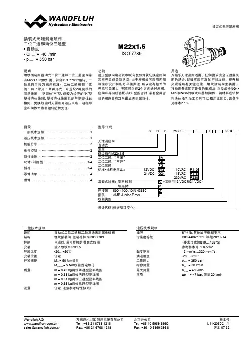
样本号1.11-2060C 1/4版本 07 32北京分公司Tel: +86 10 5969 3960Fax: +86 10 5969 3958万福乐(上海)液压系统有限公司Tel: +86 21 6768 1216Fax: +86 21 6768 1218Wandfluh AG 插装式无泄漏电磁阀二位二通和两位三通型• 直动式• Q max = 40 l/min • p max = 350 barM22x1.5用途万福乐无泄漏阀适用于任何要求完全无泄漏关断的场合,能够实现可靠的密封加载、提升和夹紧等所有关键功能。
螺纹插装阀主要用于移动设备或固定设备的集成块,以及规格NG4-Mini 和NG6的板式和叠加阀体。
钢材料或铝材料块体插孔加工刀具可以租用或购买,请参考见样本2.13。
说明螺纹插装阀直动式二位二通和二位三通座阀带有M22×1.5螺纹,用于符合ISO 7789的插孔(二位三通型按万福乐标准),二位二通阀有“常闭”和“常开”两种形式。
可选配2种规格的滑动线圈, 钢壳体“M”型,或较为经济的“K”型塑模壳体线圈,塑模壳体线圈性能与钢壳体的相同。
更换线圈时无需断开液压回路。
电枢导套和阀体外表面镀锌防护处理。
功能耐压型换向电磁铁和反向复位弹簧切换座阀阀芯至开启或关断状态,由于座阀阀芯采用两侧等面积设计和压力平衡原理,所以没有额外的开启和关闭力,液流可以在2个方向通过座阀,座阀和导向柱塞配有O -型圈密封,带有金属密封的阀座具有双向截止无泄漏特性。
一般技术规格说明 直动式二位二通和二位三通无泄漏电磁阀结构 螺纹插装阀,差装孔标准ISO 7789控制 电磁铁,带可更换的滑套式线圈安装 旋入螺纹M22×1.5环境温度 -20…+50℃安装位置 任意拧紧扭矩 M D = 50 Nm 插件M D max = 5 Nm 线圈固定螺母质量: m = 0.49 kg 两位两通型塑料线圈 m = 0.63 kg 两位两通型钢线圈 m = 0.51 kg 两位三通型塑料线圈 m = 0.65 kg 两位三通型钢线圈流量任意(注意参考特性极限)液压技术规格油液矿物油,其他油液根据要求污染度等级 ISO 4406:1999,等级20/18/14 (要求过滤级ß10…16≥75) 参考样本号 1.0-50/2黏度范围 12 mm 2/s…320 mm 2/s 油液温度 -20…+70℃工作压力 p max = 350 bar 标称流量 Q N = 20 l/min 最大流量 Q max = 40 l/min压降Δp = <7 bar ,流量20 l/minISO 7789目录一般技术规格 .......................................1液压技术规格 .......................................1机能符号 .............................................2电气控制 .............................................2特性曲线 .............................................2尺寸/剖面图.......................................3/4插孔 ................................................3/4零件清单 .............................................4附件 (4)型号代码S D S PM22 - - / 35 #无泄漏座阀直动式高压螺纹插件M22x1.5二位二通,“常闭” BA 二位二通,“常开” AB 二位三通 FG标准-标称电压U N :12VDC G12 110VAC R110 24VDC G24 115VAC R115 230VAC R230滑套式线圈: 塑料模制K (仅适用12 VDC 和24 VDC ) 钢壳体M 连接器 ISO 4400 / DIN 43650D 插头: AMP Junior-TimerJ 线圈类型设计代码(依据项目变化)样本号1.11-2060C 2/4版本 07 32北京分公司Tel: +86 10 5969 3960Fax: +86 10 5969 3958万福乐(上海)液压系统有限公司Tel: +86 21 6768 1216Fax: +86 21 6768 1218Wandfluh AG ******************.cn 机能符号SDSPM22-BA... SDSPM22-AB...SDSPM22-FG... 过渡机能“FG"电气控制结构湿式推力型耐压电磁铁带可更换的滑套式线圈标准标称电压 U N = 12 VDC, 24 VDCU N = 110 VAC*, 115 VAC*, 230 VAC* AC = 50至60 Hz*整流器集成在插头内可提供其他标称电压和性能的产品电压允差 ±10%,标称电压防护等级 IP 65,按EN 60 529(如果安装正确)相对暂载率 100%DF (见样本1.1-430)切换循环 15'000/h工作寿命 107(理论切换次数)连接/电源 具体见型号代码电磁铁类型: -钢线圈(M.35/16) (样本1.1-170)-塑料线圈(K.35/16)(样本1.1-172)p=f (Q ) 低于标称电压10%和在最高环境温度时的特性极限 二位二通型,“常闭”[BA]p=f (Q ) 低于标称电压10%和在最高环境温度时的特性极限 二位二通型,“常开”[AB]p=f (Q ) 低于标称电压10%和在最高环境温度时的特性极限 二位三通型[FG]Δp =f (Q )压力损失/流量特性流动方向品种1→2 2→1SDSPM22-BA-…/ “M” 1 2SDSPM22-BA-…/ “K”34流动方向品种1→2 2→1SDSPM22-AB-…/ “M” 1 2SDSPM22-AB-…/ “K”12流动方向品种1→22→1 2→3 3→2SDSPM22-FG-…/ “M” 4 1 2 3SDSPM22-FG-…/ “K”4156特性曲线 油液黏度 υ=30 mm 2/s备注!在不同的应用回路中,实际通流量允许大于额定流量,但是在换向期间,总流量(3→2和2→1)必须不大于Q=30 l/min 。
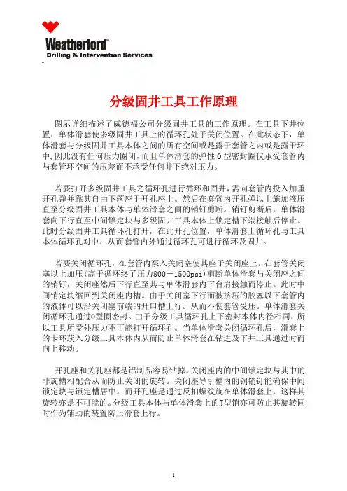
-_________________________________________________________________________________________ _分级固井工具工作原理图示详细描述了威德福公司分级固井工具的工作原理。
在工具下井位置,单体滑套使多级固井工具上的循环孔处于关闭位置。
在此状态下,单体滑套与分级固井工具本体之间的所有空间或是露于套管之内或是露于环中,因此没有任何压力圈闭,而且单体滑套的弹性O型密封圈仅承受套管内与套管环空间的压差而不承受任何井下绝对压力。
若要打开多级固井工具之循环孔进行循环和固井,需向套管内投入加重开孔弹并靠其自由下落座于开孔座上。
然后在套管内开孔弹以上施加液压直至分级固井工具本体与单体滑套之间的销钉剪断。
销钉剪断后,单体滑套向下行直至中间锁定块与多级固井工具本体上锁定槽下端接触后停止。
此时分级固井工具循环孔打开,在此开孔位置,单体滑套上循环孔与工具本体循环孔对中,从而套管内外通过循环孔可进行循环及固井。
若要关闭循环孔,在套管内泵入关闭塞使其座于关闭座上。
在套管关闭塞以上加压(高于循环终了压力800-1500psi)剪断单体滑套与关闭座之间的销钉,关闭座然后下行直至其与单体滑套内下台肩接触而停止。
此时中间销定块缩回到关闭座内槽。
由于关闭塞下行而被挤压的胶塞以下套管内的液体可以沿关闭塞前端的开口槽上行。
从而不使套管受压。
单体滑套关闭循环孔通过O型圈密封。
由于分级工具循环孔上下密封本体内径相同,所以工具所受外压力不可能打开循环孔。
当单体滑套关闭循环孔后,滑套上的卡环莰入分级工具本体内从而防止单体滑套在钻进及下井工具通过时而向上移动。
开孔座和关孔座都是铝制品容易钻掉。
关闭座内的中间锁定块与其中的非旋槽相配合从而防止关闭的旋转。
关闭座导引槽内的铜销钉能确保中间锁定块与锁定槽居中。
而开孔座是通过反扣螺纹旋在单体滑套上,这样其旋转亦是不可能的。
分级工具本体与单体滑套上的J型销亦可防止其旋转同时作为辅助的装置防止滑套上行。

中国冲床企业大全_国内冲床品牌大全内容来源网络,由深圳机械展收集整理!更多冲床设备展览展示,就在深圳机械展的金属成形机床展区!锻压工业的柔性自动化发展不断加快。
冲压设备应用于汽车、航空、电子、家电等工业领域。
以下为你展示中国冲压企业,国内冲床品牌,譬如:沃得,杨力,杨锻,厦锻,徐锻,内锻、米斯克,奥玛特,易锻、大东、迈德赫、鑫科瑞、环球、洪生、友利、西湖、义盛、华韩、沪机等等。
中国冲压企业——济南二机床集团有限公司济南二机床建于1937年,拥有试验设备仪器上百台(套),其锻压设备类,可提供60t-5000t的各种规格机械压力机、冲压生产线、大型多工位机械压力机、大型数控液压机、数控折弯机等。
中国冲压企业——江苏亚威机床股份有限公司江苏亚威机床股份有限公司创建于1956年,公司研发制造销售数控转塔冲床、数控折弯机、数控激光切割机、金属平板加工自动化系统、金属卷板加工自动化生产线、线性和水平多关节机器人等智能、自动化产品中国冲压企业——江苏扬力集团股份有限公司集团致力于冲压、锻造、折弯、剪切、激光加工等各类金属板材加工设备的开发研制,拥有80万平米厂房及各类加工装备,具备年产铸件10万吨、钢结构件20万吨、整机5万台套的生产能力和金属板材加工解决方案的提供能力,产品应用于汽车、家电、五金、电子、电气等生产领域,并远销欧美、东南亚等几十个国家和地区。
中国冲压企业——江苏金方圆数控机床有限公司江苏金方圆数控机床有限公司是能够规模生产数控转塔冲床、数控折弯机、数控剪板机、激光切割机和柔性生产线的企业。
公司用户所在行业近30个类别,销往全国并出口俄罗斯、印度、阿根廷、英国、美国及东南亚、中东等国家和地区。
金方圆公司生产的产品有数控机械、液压、高速液压、单电伺服和双电伺服转塔冲床;数控碟片、光纤、二氧化碳精密激光切割机;数控液压、高速液压、电伺服折弯机;数控液压闸式剪板机;数控母线生产线等自动化生产线产品。
中国冲压企业——齐齐哈尔二机床(集团)有限责任公司齐齐哈尔二机床(集团)有限责任公司1950年10月于沈阳北迁建厂,其中,为国防、军工、航空、航天、船舶、汽车、能源等行业和领域提供单机超百吨装备2000余台。

Watch short installation videos at /video | Register your system at /warranty Installation Instructions:DF4TOOLS REQUIREDAdjustable wrench (that opens to about 1”), 1/2” open end wrench, Phillips screwdriver, 3/8” socket, 7/16” deep socket, 7/32” Allen wrench, T30 Torx driverALUMINUM FORD F1505’6” BED LENGTH 2015-CURRENTVERSION |******************|208.806.0251▼ READ BEFORE YOU INSTALL DECKED ▼DON’T use power tools to assemble or install the DECKED system. Impact wrenches and other power tools can over tighten and damage components (aside from drilling drain holes in ammo cans).DON’T over tighten J-hooks during installation. J-hooks need to be snug to keep system from moving around, but should NOT be cranked down.DON’T over torque any bolts, particularly the bolts attaching the center vert to the deck halves.TAILGATE ammo cans have flat bottoms; CABSIDE ammo cans are narrow at the bottom.NOTE: You will need a buddy with exactly two steps.Need Help? Watch our detailed installation video or give us a call. We’re happy to help!******************|208.806.0251|/INSTALLVIDEO▼ ASSEMBLY OVERVIEW ▼C-CHANNELTAILGATE AMMO CANCABSIDE AMMO CANDRIVER SIDE DECK HALFJ-HOOK ATTACHMENTSAMMO CAN DRAIN HOLES: TO DRILL ORNOT TO DRILL•Do you use a Tonneau or shell over your DECKED system?There is no need to drill holes.•Does your DECKED system live outside in the elements?The ammo cans will likely get water in them. You’ll need to drill holes in the ammo cans. There are two d imples in the bottom of each ammo can. Drill a 3/8” hole at each dimple.PREPARE BED: INSTALL SHIMS• There are 3 SHIMS provided:•Using the information in the respective circular detail views:a) Clean the surfaces thoroughly where the shims will be located (isopropyl alcohol isrecommended).b) Remove the layer of tape on the bottom of the shim to expose the adhesive surface.c) Place the shim and apply with pressure. NOTE: Repeat DETAIL A on passenger side.DETAIL A Center shim over cabside bolt (blue). Repeat on passenger side.PREPARE BED : BRACKET INSTALLATION • T he Aluminum Ford F150’s require a shim between both cabside ammo can brackets and the truck.• R emove cabside factory tie-downs on both sides of truck bed (T30 Torx driver) and SAVE THE BOLTS .• A luminum and coated steel don’t like each other. Install cabside ammo can brackets on both sides of the truck with the soft rubber shim placed between the bracket and the sidewall; bag 3A. NOTE: Use factory tie down bolts for DECKED brackets.TIE-DOWN BRACKETTIE-DOWN BRACKETSTEP 1: DRIVER SIDE DECK ASSEMBLY • Loosely bolt C-channel to the ledges on the inside of the two ammo cans. Make sure bolt head is on the C-channel side, not inside ammo can; bag 1A. NOTE: The small rectangular slot in theC-channel indicates the tailgate end.• L ine up the deck (sticker indicates driver side deck half) on top of the C-channel/ammo can assembly and the vert bosses. NOTE: Tailgate side of vert has an axle hole at the bottom (see below).• B olt deck to C-channel/ammo can assembly; bag 1B for driver side tailgate ammo can, bag 1C for driver side cabside ammo can. NOTE: bag 1C only has 4 screws for 6 spots. Do not use the two spots along the cabside edge of ammo can (see STEP 3 for reference).• Go back and tighten loose bolts connecting ammo cans to C-channel.• Bolt the deck to the vert; bag 1D. Do not use power tools.• Grab your buddy to help you lift assembly onto driver side of truck bed.DRIVER SIDE TAILGATE AMMO CAN (TOP VIEW)AXLEL E STEP 2: INSTALL AXLES1). Install the driver side tailgate ammo can axle; bag 2A.• Rotate the axle from its inbound side using a wrench on the “flat” end. Nut is included in bag and can be held with adjustable wrench while tightening. NOTE: Axles should be tight enough that the axle end is difficult to spin with a 1/2” wrench.2). Repeat on passenger side tailgate ammo can; bag 2A .3). I nstall vert axle; bag 2B.PASSENGER SIDE TAILGATE AMMO CAN (TOP VIEW)AXLE TAILGATESTEP 3: INSTALL DRIVER SIDE DECK HALF • I nsert the J-hook through the tailgate side hole on the driver side tailgate ammo can and loosely affix it to the tie-down bracket with spherical washer, flat washer and nut; bag J7.• B olt deck, cabside ammo can and bracket together by aligning bracket with the cabside lipof the ammo can; bag 3B. Use screwdriver to align grab nuts inside bracket.IMPORTANT: Leave all J-hook screws and cabside ammo can bracket screws loose until entire deck is in place.STEP 4: PASSENGER SIDE DECK ASSEMBLY • Loosely bolt C-channel to the ledges on the inside of the two ammo cans. Make sure bolt head is on the C-channel side, not inside ammo can; bag 4A. NOTE: The small rectangular slot in theC-channel indicates the tailgate end.• L ine up the deck (sticker indicates passenger deck half) on top of the C-channel/ammo can assembly and the vert bosses. NOTE: Tailgate side of vert has an axle hole at the bottom.• B olt deck to C-channel/ammo can assembly; bag 4B for driver side tailgate ammo can, bag 4C for driver side cabside ammo can. NOTE: bag 4C only has 4 screws for 6 spots. Do not use the two spots along the cabside edge of ammo can (see STEP 3 for reference).• Tighten bolts connecting ammo cans to C-channel.• Grab your buddy to help you lift assembly onto passenger side of truck bed.RECTANGULARHOLE IN C-CHANNELSTEP 5: INSTALL P ASSENGER S IDE D ECK H ALF • B olt deck, cabside ammo can and bracket together by aligning bracket with the cabside lipof the ammo can; bag 5A. Use screwdriver to align grab nuts inside bracket.• I nsert the J-hook through the tailgate side hole on the passenger side tailgate ammo can and loosely affix it to the bracket with with spherical washer, flat washer and nut; bag J7.• Bolt passenger side deck half to the vert; bag 5C (just like step 1D). Make sure all boltsconnecting deck to vert are snug, but no power tools.• MAKE SURE THE VERT IS IN THE CENTER OF YOUR BED; the gaps on either sidewall may not be equal.• Alternately and gradually tighten all J-hooks and cabside ammo can bolts to ensure deck iscentered and secure. Do not tighten one side of J-hooks all the way in one step.• T here is a left and a right corner bracket for each drawer–bolt brackets in place.(use the 2” bolts for the upper back wall bracket hole); bags 6A and 6B.• Use tube brace with two bolts to connect the two corner brackets; bag 6C.• Insert axle through wheel and affix to drawer bracket; bag 6D. Do this for each wheel (4 times).• T urn drawer upside down and align the holes in the L-braces (loose in system box) with the drawer holes. NOTE: Start L-brace with hole closest to handle.• S imply use your thumb to push the weld nuts into each hole. Once weld nuts are in place, turn the drawer upright and insert the screws (snug but not too tight); bag 6E.• R epeat for all drawer sides.OF HANDLE NOTCHIN HANDLE NOTCHSTEP 8: INSTALL DRAWERS• Save yourself the headache, watch this short installation video: /videotailgatewheels.• Install optional drawer braces (instructions included in bag); bag 8A.• Install drawer by sliding wheels into their two channels (C-channel and vert).• Install remaining tailgate side wheels onto their axles; bag 8B.NOTE: Placing a spacer under the drawer to raise it into position makes this easier (ammo can lids work well).• P lace weather stripping on top of the tailgate side drawer edge with the wiper facing CABSIDE;bag 8C.STEP 9: THE FUN STUFFCAUTION: These are small gauge screws–light, hand-tightening is all that is required.• Center and screw on the ruler/edge guard; bag 9A.• Screw on the bottle opener; bag 9A.• U sing your favorite beverage, test the bottle opener, and think about how jealous your friends are going to be.9A9A#DECKEDUSA | @DECKEDUSA。
RDAS 系列动力押扣开关适用于交流50Hz 或60Hz 、额定电压至380V 。
额定工作电流至10A 。
可以直接控制小型三相电动机,广泛应用在食品、包装、纺织等产业机械设备中。
产品符合:GB/T 14048.5标准。
□ 周围空气温度为:-5℃~+40℃,24小时内其平均值不超过+35℃;□ 海拔高度:不超过2000m ;
□ 大气条件:在最高温度为+40℃时,空气的相对湿度不超过50%,在较低的温度下可以允 许有较高的相对湿度,例如+20℃时达90%。
对由于温度变化偶尔产生的凝露应采取特殊 的措施;□ 污染等级:3级;
□ 安装类别:Ⅲ类;
□ 无显著摇动、冲击振动和没有雨雪侵袭的地方;
□ 在无爆炸危险的介质中,且介质中无足以腐蚀金属和破坏绝缘的气体和尘埃。
表2
正常工作条件和安装条件
主要技术数据
产品概述
选型指南
表
1
242
□ 订货时请指明按钮的完整型号、规格和数量。
□ 例:型按钮只,意指约定发热电流为的一般型按钮只。
RDAS-211BS 5010A
50图
1
表3
外形及安装尺寸
订货须知
243。
HADEF葫芦的所有系列及型号HADEF葫芦的所有系列及型号HADEF (HEINRICH DE FRIES GMBH)总部位于德国Düsseldorf,迄今已经有超过100年的历史,是提升工具领域的专业厂商。
多年来,一直坚持生产高品质的产品,得到了全世界的认可。
HADEF为诸多领域提供了具有价格竞争力的创新解决方案,提升、牵移、装卸重物,油罐倒装焊接,如各种大中型砼、钢结构及机械设备的安装和移动,适用于建筑安装公司、厂矿的土木建筑工程及桥梁施工、电力、船舶、汽车制造、建筑、公路、桥梁、冶金、矿山、边坡隧道、井道治理防护等基础建设工程的机械设备。
HADEF 产品系列介绍:手动环链葫芦:1容量范围从250到50,000公斤 2镀锌负载和手动链3质量可靠手推车: 1滚动轴承中的机车车轮 2集成脱轨和碰撞保护电动环链葫芦:1容量范围从125到60000公斤2紧凑的设计3精密制造气动环链葫芦1带有过载保护2带紧急停止功能的吊坠控制一、HADEF手动环链葫芦包括:手动手推车葫芦、不带手推车的手动环链葫芦、棘轮葫芦1、HADEF手动手推车葫芦型号介绍:21/12 HH:带手动小车的正齿轮葫芦-烧结刹车片21/12 HR-带推式小车的正齿轮葫芦-烧结制动衬片23/09 HH-铝齿轮正齿轮葫芦,带手推车23/09 HR-带有推拉式手推车的铝制正齿轮葫芦24/12 HH-带手动变速小车的正齿轮葫芦-通过滑动离合器保护葫芦24/12 HR-带推式小车的正齿轮葫芦-带有滑差离合器的葫芦保护240/12 HH-带手推车的直齿葫芦-专业线240/12 HR-带推式旅行车的正齿轮葫芦-专业线26/12 HH-带手动小车的正齿轮葫芦-带葫芦保护-5吨(最大25吨)27/12 HH-带手动齿轮小车的正齿轮葫芦-新制动系统27/12 HR-带推式小车的正齿轮葫芦-烧结制动衬片28/12 HH-带手动小车的正齿轮葫芦-低净空配置28/12 HR-带推式旅行车的正齿轮葫芦-低净空配置29/12 HH-带手推车的直齿葫芦-超低净空配置2、HADEF不带手推车的手动环链葫芦型号介绍11/09铝制正齿轮葫芦12/12-正齿轮葫芦-新的刹车片14/12-正齿轮葫芦-新的刹车片-具有葫芦保护16/12 HH-直齿轮葫芦-通过滑动离合器保护葫芦-5个最大50吨容量8/12-齿轮葫芦-专业线9/12-正齿轮葫芦-具有葫芦保护3、HADEF棘轮葫芦型号介绍:25/19棘轮提升机-专业线50/07棘轮提升机-专业线53/07铝制棘轮葫芦53/07棘轮提升机二、HADEF手推车包含:电动手推车、手动手推车、气动手推车、推手推车1、HADEF电动手推车型号介绍:20/94 AFE:单轨电车22/90 E:单轨电车2、HADEF手动手推车型号介绍:20/94 AFH:单轨手动齿轮车209/05:单轨手推车-专业生产线209/05:单轨手扶小车,带螺栓-专业线3、HADEF气动手推车型号介绍20/94 AFP:单轨气动小车4、HADEF推手推车型号介绍:19/90:单轨手推旅行车20/94 AFR:单轨手推旅行车208/05:单轨手推旅行车-专业线208/05:单轨手推旅行车,带螺栓-专业线三、 HADEF环链电动葫芦包含:紧凑的设计葫芦、低净空配置葫芦1、紧凑的设计葫芦型号介绍:66/04 AKS-固定,带吊眼66/04 AKR-带推拉手推车AKH 66/04-带有手推车66/04 AKE-带电动推车62/05 S-固定式葫芦-专业线62/05 R-带手推车-经济型62/05 H-带手推车-专业生产线62/05 E-带电动推车-专业线2、低净空配置葫芦型号示例:28/06 ER-带推拉手推车28/06 EH-带有手推车EE 28/06-电动手推车四、HADEF气动环链葫芦型号介绍:70/06 APS-带有吊环的固定式葫芦70/06 APR-推式旅行车。
安装、操作与维护说明书大型摆阀带双作用气动驱动器168系列公称直径DN 400 – 500 mm (内径 16" – 20")本产品手册适用于以下产品订购编号:168..-….-….样品图603171CA 2018-09-19版168系列2/29 2018-09-19版 603171CA版本说明制造商: VAT Vakuumventile AG, CH-9469 Haag, Switzerland官网:电话:传真: 电子邮件: +41 81 771 61 61 +41 81 771 48 30 ***************发行方 VAT Vakuumventile AG, CH-9469 Haag, Switzerland编辑 VAT Vakuumventile AG, CH-9469 Haag, Switzerland印制 VAT Vakuumventile AG, CH-9469 Haag, Switzerland版权 © VAT Vakuumventile AG 2018未经VAT 书面许可,严禁以复印、缩微胶片等途径或利用任何其它复制工艺复制本说明书的任何部分,或通过电子系统处理、复制或分发本说明书的任何部分。
违者将赔付损害赔偿金。
VAT 原装固件以及更新后的最新款VAT 固件适用于VAT 产品。
VAT 固件含范围有限但无期限限制的用户使用许可。
除预期用途外或经许可复制VAT 固件,不得以任何其它形式复制VAT 固件或将之用于任何其它用途。
特别是,严禁将VAT 固件的复制品提供给他人。
尽管本说明书中使用了各种商品名称、品牌名称和商标等信息,但第三方不得认为这些名称不受保护且无权随意使用这些名称。
此规定符合相关品牌名称与商标法及法案的规定。
168系列目录1产品描述 (5)1.1产品标识 (5)1.2产品用途 (5)1.3相关文件 (5)1.4重要注意事项 (5)1.5技术数据 (5)2安全性 (6)2.1必读资料 (6)2.2危险等级 (6)2.3人员资质 (7)2.4安全标签 (7)3设计与功能 (8)3.1设计 (8)3.2功能 (8)4安装 (9)4.1开箱 (9)4.2将阀门装入系统 (9)4.2.1允许力度与弯矩 (11)4.3压缩空气连接 (12)4.4电气连接 (12)5操作 (13)5.1正常操作 (13)5.2升温状态下操作 (13)5.3压缩空气发生压降时的阀门特性 (13)5.4断电时的阀门特性 (13)5.4.1应急手动操作 (13)5.5三位置驱动器 (选配件) (15)5.5.1三位置驱动器的控制逻辑 (15)5.5.2调整第三位置 (15)5.6故障排除 (16)6维护 (17)6.1维护间隔时间 (17)6.2所需工具 (18)6.3更换阀板/机构单元 (18)7维修 (21)8拆装与储存 (22)8.1拆装 (23)8.2储存 (23)603171CA 2018-09-19版3/29168系列9包装与运输 (24)9.1包装 (25)9.2运输 (25)10处理 (26)11备品备件 (27)12附录 (28)12.1组装图 (28)12.2阀板机构组装图 (29)4/292018-09-19版603171CA168系列 产品描述603171CA 2018-09-19版5/291产品描述1.1产品标识制造号和订单号直接印在产品上或标示牌上。
OWNER/OPERATOR MANUALMODEL YA692D/YA696D 10 TON/ 2-1/2 TON CAPACITYAIR OPERATED END LIFTSAFETY INSTRUCTIONSFor your safety, read, understand, and fol-low the information provided with and on this jack. The owner and operator of this equipment shall have an understanding of this device and safe operating proce-dures before attempting to use. The owner and operator shall be aware that use and repair of this product may require special skills and knowledge. Instruc-tions and safety information shall be conveyed in the operator's native language before use of this device is authorized. If any doubt exists as to the safe and proper use of this device, remove from service immediately.Inspect before each use. Do not use if there are broken, bent, cracked, or dam-aged parts (including labels). Any device that appears damaged in any way, oper-ates abnormally or is missing parts, shall be removed from service immediately. If the device has been or suspected to have been subjected to a shock load (a load dropped suddenly, unexpectedly upon it),immediately discontinue to use until jack has been inspected by a Snap-on author-ized service center. It is recommended that an annual inspection be done by qualified personnel. Labels and Opera-tor's Manual are available from manufac-turer.PRODUCT DESCRIPTIONSnap-on Air Operated End Lifts are designed to lift, but not sustain, rated capacity loads. Intended use: To engage the metal bumper of a vehicle and raise for the purpose of service and/or repair of vehicle components. After lifting, loads must be immediately supported by appropriately rated jack stands. Check vehicle's factory service and/or repair manual for proper lift points.BEFORE USE1. Verify that the product and the application are compatible.2. Read this manual completely and familiarize yourself thoroughly with the product, its components andrecognize the potential hazards asso-ciated with its misuse before using this product.3. Ensure that jack rolls freely, the air cylin-der operates smoothly, raises and lowers the unloaded saddle throughout the lift range before putting into service.4. Ensure the jack is loaded on center with the saddles placed equal distance from the center.5. Replace worn or damaged parts and assemblies with Snap-on replacement parts only. (See Replacement Parts section). Lubricate as instructed in Maintenance section.6. Connect air nipple (not provided) to air input port before connecting air hose.Note : Use only NPT thread size air nipple.Tighten securely to prevent accidental re-moval of components while in use. Take care not to introduce compound into portorifices.• Study, understand, and follow all instructions provided with and on this device before operating this device.• Do not exceed rated capacity.• This is a lifting device only.• Center load on saddle.• Never lift vehicle which cannot roll freely forward and backward during lift.• After lifting, immediately transfer the load to appropriately rated vehicle stands.• Never work on, under, or around a load supported only by this device.• Use only on hard, level surfaces capable of sustaining rated capacity loads.• Do not move or dolly loads with this device.• Do not modify this device.• Do not use adapters or accessories that are not provided initially.• Lift only on areas of the vehicle as specified by the vehicle manufacturer.• Failure to heed these markings may result in personal injury and/or property damage.! WARNING• Esta es una simple advertencia.Por favor lea las instrucciones y advertencias en inglés! ADVERTENCIAOPERALiftingCaution: 180 degrees.manufacturer's recommended lift points.6. To raise jack, slowly push the lift control lever toward the right until saddles con-tact with the lift point. !STOP! RELEASE THE LIFT CONTROL LEVER! Confirm that the saddles are positioned cor-rectly, then continue to push the lever until load reaches desired height.Simply release the lever to stop.7. Transfer the load immediately to ap-propriately rated jack stands (always used in pairs).toward the left.* To disengage safety bar: Push safety bar lever towards front end of the jack.MAINTENANCE1. Lubricate all moving parts with oil/grease.2. A periodic coating of light lubricating oil to pivot points, axles and hinges will help to prevent rush and ssure that wheels and caster assemblies move freely.3. When not in u se, store the end lift with cylinder fully lowered.TROUBLESHOOTINGBe sure all tools and personnel are clear before lowering load.! WARNING35-3/8"8"YA696D2-1/2 Ton24-3/4"23-1/4" to 41-1/4"200Replacement Parts List for YA692DReplacement Parts List for YA696DLIMITED WARRANTY STATEMENTSnap-on Tools warrants this product to be free from defects in material and workmanship for a period of 2 years from date of purchase. This warranty applies to the original purchaser (end user) only and is not transferable. Damaged components and assemblies i.e. bent ram and pump pistons, dented reservoirs, cracked or altered components, are the result of mis-use, mis-application or a combination of both. These conditions will not be considered for warranty credit. We have complete confidence that the Snap-on prod-uct you purchase will meet or exceed your performance requirement. However in the unlikely event that a Snap-on product fails due to material or workmanship defect within the warranty period you may contact your retailer for disposition or you may contact an Authorized Service Center listed in the product owner’s manual. Except where such limi-tations and exclusions are specifically prohibited by law, the consumer’s sole and exclu-sive remedy shall be the repair or replacement of the defective product. Snap-on shall not be liable for any consequential or incidental damage or loss whatsoever, and the duration of any and all expressed and implied warranties, including without limitation, any warran-ties of merchantability and fitness for a particular purpose, is limited to a period of 2 years from date of purchase. Some States do not allow the exclusion or limitation of incidental or consequential damages, so the above may not apply to you. This warranty gives you specific legal rights. You may also have other rights which vary from state to state.Manufactured for Snap-on Tools Companymemo.。