ZSM-5-SUPPORTED Fe, Ru, Pd and Rh CATALYSTS
- 格式:pdf
- 大小:916.68 KB
- 文档页数:17

Material Sciences 材料科学, 2011, 1, 10-16doi:10.4236/ms.2011.11003 Published Online April 2011 (/journal/ms/)Recent Progress in Catalytic Materials for Catalytic Combustion of Chlorinated Volatile OrganicCompounds#Xuehua Yang1, Aidong Tang1*, Xianwei Li21School of Chemistry and Chemical Engineering, Central South University, Changsha2Institute of Environment and Resource, Baosteel Co., Ltd., ShanghaiReceived: Mar. 14th, 2011; revised: Apr. 15th, 2011; accepted: Apr. 20th, 2011.Abstract: The research progress in the catalytic combustion of Cl-VOCs(Chlorinated Volatile Organic Compounds) is reviewed. In this review, the effects of the active species, catalyst support, water vapor and coking on the catalytic combustion reaction were summarized. The research related to noble metal catalysts mainly focuses on developing new supports and dual noble catalysts. The research on non-noble metal cata-lysts concentrate on the development of transition metal mixed oxide, perovskites and spinel catalysts; The chlorination of active species is regarded as an important reason for catalyst deactivation. Besides, the effects of water vapor and coking deactivation on the catalytic combustion process are discussed with considering the practical application. This review will be helpful in choosing an appropriate catalyst and the optimal reac-tion conditions for the removal of Cl-VOCs by catalytic combustion with high activity and high stability. Keywords:Catalyst; Noble metal; Metal oxide; Chlorinated Volatile Organic Compounds; Deactivation催化燃烧Cl-VOCs催化材料的研究进展#杨学华1,唐爱东1*,李咸伟21中南大学化学化工学院,长沙2宝钢股份研究院环境与资源研究所,上海收稿日期:2011年3月14日;修回日期:2011年4月15日;录用日期:2011年4月20日摘 要:从催化剂活性组分、催化剂载体、催化剂失活三个方面,对近年来催化燃烧含氯挥发性有机物(Cl-VOCs)催化剂的研究进行了总结。


文章编号:1001-9731(2021)05-05001-05Fe、Ce双助剂增强型Nb/TiO2催化剂的制备及其NH3-SCR性能研究*许俊强,杨传玲,余海杰,张强,郭芳,唐田,张艳容(重庆理工大学化学化工学院,重庆400054)摘要:采用柠檬酸络和法制备了Fe.Ce改性的系列Nb-Fe-Ce/Ti()2催化剂,考察了Fe.Ce助剂的引入对Nb/TiO2催化剂的低温活性和反应温度窗口的影响。
通过X射线衍射(XRD)、氮气吸附-脱附(BET)、热重(TG)、程序升温还原(H-TPR)等手段对催化剂进行了表征。
结果表明,Fe、Ce改性的Nb/TiO2催化剂在NH-SCR反应中表现出较优的低温脱硝活性和较宽的操作温度窗口。
优化配方后得到的10%Nb-0.7%Fe-3%Ce-TiO2催化剂,在300°C时,其对NO转化率达100%,操作温度窗口为T80为225〜500°C,这可能归因于Fe.Ce 助剂引入后催化剂具有较强的Nb-Fe-Ce-Ti相互作用力和较好的氧化还原性能。
关键词:选择催化还原:NH3;改性制备;宽温活性中图分类号:TQ221文献标识码:A DOI:10.3969/.issn.10019731.2021.05.0010引言氮氧化物(NO J是造成雾霾、臭氧空洞、酸雨和光化学烟雾的主要大气污染物之一[-3]。
随着国VI排放法规的实施,对NO’的排放要求越来越严格,因此开发高效的氮氧化物(NOQ催化剂至关重要[-2],以NH3为还原剂的SCR催化剂是研究的热点[-10]0在现有的NH3-SCR催化剂中,V基催化剂因其在300-400C的中温段具有较好的脱硝性能被广泛使用,但V基催化剂存在操作温度窗口窄和有毒等缺陷,其应用受到限制,因此开发宽温且环保的催化剂显得尤为重要[47]。
过渡金属因具有优异的氧化还原性能、热稳定性高和使用寿命长等优点被广泛应用于当前的NH3-SCR研究中[316]。

ZSM-5分子筛的结构及催化性能研究进展2005年l0月第24卷第5期绵阳师范学院JournalofMisnyangNormalUnivemityOct.,2005V o1.24No.5M—ZSM一5分子筛的结构及催化性能研究进展薛英,昊宇",万家义(1.I~;ll大学化学学院,四川成都610064;2.I~;ll省产品质量监督检验检测院,四川成都610031)摘要:撂宛了ZSM-5分子筛的晶体蛄构,孔结构及酸性质:对通过离子变换对其表面进行优化以提高催化活性方面的研究工作进行了阐迷;对Cu-ZSM-5分子筛上NO直接催化分解反应提出了:4CuO=2cO+O2,2Cu20+4NO=4CuO+2N2+02的反应机理.关键词:ZSM-5分子筛;x-射线衍射;孔结构;酸性质;综述中圈分类号:0643.32文献标识码:A文章编号:1672-612x(2005)05..0001-04O引言ZSM-5是一类硅铝酸盐沸石分子筛,其组成中的T-0(T=Si,A1)四面体构成内表面很大的空隙,并进一步连接成孔径均匀的直形孔道和正弦形孔道….这些孔道特定的孔径与某些分子的动力学直径相近,故ZSM-5分子筛容易吸附/脱附NOFCC汽油,苯,取代苯等小分子,并具有择形催化性能【2一J.ZSM-5为高硅/铝比分子筛,具有丰富的B酸位和L酸位,这些酸位形成强酸中心,中等强度酸中心和弱酸中心,它们的强度和分布具有可调节性,因此可以用作固体酸催化剂.通过改变合成条件和合成方法,离子交换,表面修饰,扩孔技术等改性方法得到的离子交换分子筛M—ZSM-5广泛用作DeNO.[5,芳构化[1圳,裂化¨,汽油邻氢降凝[2以及其它反应[3?22-24]的催化剂.ZSM-5分子筛白问世以来,已经对工业生产起了重要的作用,并且得到了广泛研究.本文结合本课题组以往及近期的研究工作[6-|】探究了近年来对ZSM-5分子筛进行表面修饰,对其酸性及孔结构进行优化,以提高其催化活性及稳定性方面的研究进展;强调催化剂的结构,表征与性能及用途的关联,并提出了Cu-ZSM-5分子筛上NO直接催化分解的反应机理.1ZSM_5分子筛的晶体结构与Ⅺ表征催化剂的性能和用途是由其结构决定的.x一射线衍射(XRD)单晶结构分析的结果表明:ZSM-5分子筛中的T-O四面体组成十元环,十元环共边连接形成螺旋链.螺旋链可经其图形中的2次对称轴旋转180.而得到.螺旋链进一步彼此连接则形成具有周期性结构的ZSM-5分子筛晶体.ZSM-5分子筛可由螺旋链按对称面的反映操作(相当于照镜子)而得到.O的离子半径为1.35A,据此可以推知,由T.O四面体彼此连接并周期性重复而在ZSM-5分子筛晶体中形成的直形孔道平行于(010)方向,孔径为5.6×5.4A;而沿着(too)方向的正弦形孔道孔径则为5.1×5.5A,两种孔道在(001)方向彼此重叠并扩大….这种骨架结构对应于ZSM-5分子筛XRD多晶粉末谱中20=8o附近的两个衍射峰,以及2O=25.附近的特征五指峰.不同制备条件,不同制备方法,不同Si/A1比的ZSM-5分子筛及其经改性的MZSM-5分子筛的粉末衍射谱图中一般都会保持这些特征峰.7I圳'.XRD结构分析还发现,ZSM-5分子筛有简单单斜(monoclinicP)和简单正交(orthorhombicP)两种晶型,这两种晶型的骨架结构类似,均如上所述,两种晶型的晶胞参数也比较接近.并且,粉末图中20=29.附近的单峰是正交晶系ZSM-5分子筛的特征峰,该位置的衍射峰分裂为双峰则是属于单斜晶系的ZSM-5分子筛的特征'.收稿日期:2005-08-08.作者筒介:薛荚(1962一),女,教授,博士导师.主持国家自然科学基金资助课题1项,作为主研人员参与完成国家自然科学基金九五重大课题,国家博士点基金课题,国家I然科学基金八五重大课题各1项,获各种奖励(成果)5项.迄今已在国内外重要学术刊物上发表学术论文22篇(其中,英文论文7篇,近两年米被scI收录的论文1O篇).主要从事理论化学研究.l?采用XRD结构分析技术,不仅可以确定催化剂的物相,还可以得到晶粒尺寸,晶胞中原子的位置,原子之间的距离,氢键键长和键角等结构信息.借助于量子化学理论计算,还可以确定催化剂的活性物种和活性位,并且可以探讨催化反应的历程和机理等蚓.总之,XRD技术对ZSM-5分子筛催化剂的表征是十分重要和非常有效的.2ZSM_5分子筛的酸性质及孑L结构研究表明,添加助剂,表面修饰,以及水热处理等可以对ZSM-5分子筛的酸性质及孔结构等进行优化.一般说来,ZSM-5分子筛催化剂的酸量随Si/A1比增大而减小,酸强度则随之降低.Si/A1比越大,ZSM-5分子筛催化剂的耐酸性和稳定性亦越强.作为烃类转化反应催化剂的ZSM一5分子筛,其酸性影响烃的转化率,产品分布和催化剂寿命则取决于酸强度的分布.分子筛的酸性较大较强,特别是适中的B酸有利于芳构化及芳烃和烯烃的烷基化.IR谱中1545cm和1635cm附近的吸收峰表征Cd—ZSM-5分子筛中B酸的存在,1454cm左右则是其L酸的特征吸收峰J,3610cm处的吸收峰表征CuC1/H-ZSM-5分子筛的B酸¨引.由朱向学等¨副计算所得丁烯裂解反应的热力学数据知,ZSM-5分子筛催化剂较强的酸性有利于氢转移及芳构化反应的进行,降低其酸性可以提高目的产物丙烯和乙烯的选择性和收率,合适的反应条件可以有效抑制氢转移等副反应.毛东森等副的研究表明,合成气直接制二甲醚反应的催化剂Cu-ZnO—A10一ZSM-5分子筛的弱和中等强度的酸性位是生成二甲醚的活性中心,强酸位则是生成烃类副产物的活性中心.高温水热处理可以减少催化剂的强酸中心,提高二甲醚的选择性,但同时也会使弱酸中心的数量减少而降低催化剂的活性.Mg常用于调节MZSM-5分子筛催化剂的酸性,添加适量MgO可明显降低HZSM-5分子筛中强酸中心的数量,并能将较强的B酸中心转化为较弱的L酸中心.NH3-TPD常用于表征催化剂的酸性质,其峰面积可以代表酸量,峰位置及峰高可以代表酸强度.催化剂表面的酸度还可以用电位滴定法确定,也可以用Hammer指示剂法确定催化剂总的和外表面的酸度分布.ZSM-5分子筛的孔结构是决定其择形催化性能的重要因素.除XRD技术是表征分子筛孔结构的强有力武器之外,一般还用比表面仪采用N:吸附法测定多相催化剂的孔径和孔容积等.研究表明,乙烯齐聚反应的最终产物将受分子筛孔结构和内表面酸性位和外表面酸性位双重作用的影响.为了提高直链烯烃产物的收率和选择性,除应选择适宜孔结构参数的ZSM-5分子筛外,还必须降低其外表面酸性位的活性.张君涛等报道NaZSM一5(26)(26=nsl/n.)分子筛催化剂经离子交换后得到的MZSM-5(M=Ba,Mo,Cd)分子筛的孔径有所扩大,有利于乙烯齐聚生成芳烃及稠环芳烃.MZSM-5经有机碱邻菲咯啉表面修饰后,产物中Ot一烯烃的选择性明提高,这是邻菲咯啉分子不仅可以在催化剂外表面吸附,而且还可以进人ZSM.5分子筛的较大孔道,并在其表面吸附使之大部分活性中心失活之故.郭新闻等的研究结果显示,对4.甲基联苯与甲醇的甲基化反应催化剂HZSM-5分子筛,采用添加金属氧化物进行改性,随MgO负载量的增加,样品的比表面积和微孑L比表面积逐渐减少,中孔的比表面积变化不大.同时,经金属氧化物改性后,减少了催化剂的酸性,抑制了产物4,4'一二甲基的异构化,脱烷基化及烷基化,使其选择性提高. 由上可见,载体ZSM-5分子筛的孑L结构及酸性质对催化剂的性能和用途起着决定性作用.3Cu—ZSM-5分子筛催化剂上NO直接分解的机理金属离子交换是对ZSM-5分子筛进行改性与优化的重要方法.改性分子筛MZSM.5中,Cu—ZSM一5分子筛尤其重要.研究发现,Cu—ZSM一5是容易达到超计量离子交换的体系¨引,这是由分子筛的结构决定的.铜离子交换的Cu—ZSM-5分子筛对NO直接分解反应有很高的活性[71].高Si/A1比,铜离子交换量超过ZSM-5分子筛的单层分散阈值等,有利于提高催化剂的活性.这是因为cu是NO直接分解的活性物种,cu与cu札之问可逆的氧化还原循环使NO的直接分解成为可能.一般是以cu(Ac):或Cu(NO,):等铜盐作为cu源,采用常规浸渍法或直接混合研磨的方法制备Cu7-.5~-5分子筛催化剂. 催化剂中cu是以[Cu(OH)]存在,在NO直接分解反应的条件下,发生如下反应:2[Cu(OH)]=cu'+CuO+H0由电荷补偿原则可以知道,cu趋向于由分子筛的孔道向两个[AIO]一四面体空隙之间迁移,这对高Si/Al比ZSM-5分子筛而言,原子之间的距离太大,不合适,故cu容易还原为cu,cu 向[AlO]一四面体2?空隙迁移,同时吸附NO.NO通过cu与cu+2之间可逆的氧化还原循环而分解:4CuO=2Cu2O+O22Cu2O+4NO=4CuO+2N2+O2因为具有不需要另外加入还原剂,不会产生新的污染物等特征,直接分解无疑是脱除大气污染物NO的关键起始物,并且还是脱除NO的良好方法.Cu—ZSM-5分子筛对NO直接分解具有优良性能是由其结构决定的,Cu由分子筛的孔道向AI—O四面体空隙迁移是关键步骤,Cu与Cu之间可逆的氧化还原循环起重要作用.因此,分子筛的Si/A1比是对其催化性能有较大影响的因素之一.4ZSM-5分子筛催化剂的其它表征方法及用途Cu-ZSM-5分子筛的Cu含量可以用原子吸收光谱法测定,Cu元素的表面形态可以用x射线光电子能谱(XPS)仪测定.此外,rI.PR,TPD,SEM等技术也常用于催化剂的表征.H2-TPR谱中,cu还原为cu的峰在209"附近,265.附近则是cu还原为Cu的还原峰【|¨.O—rPD方法¨刮显示,Cu-ZSM-5上有三个O脱附峰,最高峰温为700K的脱附峰对应的O:脱附与催化活性有直接关联.Cu—ZSM-5催化剂0吸附量明显高于co-zsM一5,Fe—zsM_5和H—ZSM-5的O吸附量,这是其催化活性在三者中为最高的原因之一.在Cu-ZSM-5的XPS谱中cu+2的结合能为942.7eV,Cu的结合能则为933.1eV【6.】引.我们近期的研究工作表明,nsi/n^l比分别为25,38和5O的Cu—ZSM-5,Cu—Ce—ZSM-5,Cu—La.ZSM-5以及Cu —Ag—ZSM5分子筛催化剂的XRD谱中,20=23—26.出现特征五指峰,9.附近有两个较强的衍射峰,这与前述结果一致. 南开大学李赫喧教授等用水热晶化法合成了ZSM-5分子筛.合成时不用胺类模板剂,而是用廉价易得的工业水玻璃,硫酸铝和硫酸为原料,成本仅为国外胺法合成的1/9.合成工艺简单,分子筛产率高,生产周期短,产品结晶度好,并且避免了胺对环境的污染.又因为不需要经过焙烧脱氨,可以直接进行离子交换,简化了催化剂制备工艺.该法突破了国际上合成ZSM-5分子筛必须用胺类作模板剂的传统理论和方法.南开大学在用乙二醇合成乙醚的生产中使用该法生产的ZSM-5分子筛催化剂取代三氟化硼催化剂后,产率提高20%,主要原料成本下降2l%,每吨产品成本降低2000元,并且消除了氟化硼对设备的腐蚀和对环境的污染.该项目获得国家教委科技进步二等奖.他们用ZSM-5分子筛催化剂由乙醇脱水制乙烯,与采用传统的氧化铝催化剂比较,反应温度降低100.C,空速高1—2倍,节省了能源,提高了生产效率.此项目获得国家发明奖四等奖.他们还将ZSM-5分子筛催化剂用在乙苯,乙醇合成对二乙苯的生产中,可使对二乙苯选择性达到95-98%,这是生产长期依靠进口的二甲苯分离吸附剂的一种催化合成新工艺,使我国"对乙二苯"的生产将很快实现国产化.此外,中国石化总公司抚顺石油科学研究院用该ZSM-5分子筛制的FDN一1无胺型临氢降凝催化剂,已经可以取代从美国莫尔比公司进口的降凝催化剂.胜利炼油厂在引进装置上采用ZSM一5分子筛催化剂后,每批催化剂可节约外汇126万美元.北京大学林炳雄教授等首次应用多晶x射线衍射方法,对国内外用典型方法制备的ZSM-5分子筛进行了体相结构和性能的研究,发现了该类型分子筛结构的易变性以及分子筛晶格内存在强度,酸度及稳定性不同的两类质子酸中心sj和S.i'两类质子酸中心的强度和空间位置不同,因而有各自的催化功能.由上可见,ZSM-5分子筛的结构决定了它优良的催化性能和广泛的用途.参考文献:[1]D.H.Ohon,C.T.KokotaUo,wton.Crystalstruetureandstructure-relatedproperti esofZSM-5[J].J.Phys.Chem.1981.85(15):2238-2243.[2]张培青,王祥生,郭洪臣,等.水热处理对纳米HZSM-5沸石酸性质及其降低汽油烯烃性能的影响[J].催化,2003,24(2).900—904.[3]郭新闻,王祥生,沈建平,等.改性HZSM-5上4一甲基联苯与甲醇的甲基化反应性能[J].催化,2003,24(5):333—337.[4]张君涛.张耀君,梁生荣.表面修饰对金属负载型HZSM-5催化剂乙烯齐聚性能的影响[J].分子催化,2005,19(2):121—124.[5]李哲,张海荣,黄伟,等.不同Si/AI比对Mo/ZSM-5催化性能的影响[J].分子催化.2005,19(2):104—108.[6]万家义.余林,陈豫.Cu?M/ZSM-5(M=ce,La.Ag)催化剂的表征及其对NO直接分解催化活性的研究[J].化学研究与应用,1999,11(1):8—12.-3?[7]万家义,余林,陈豫.Cu-ZSM-5上NO催化分解的研究[J].四川大学,1999,36(1):126—130.[8】高玉英,万家义,衰永明,等.CuCe./ZSM-5催化剂的TPR及动力学研究[J].化学研究与应用,2000,12(2);137—141.【9]M.1wamoto,H.Y ahiro,K.Tanda,eta1.Removalofnitmsenmonoxidethroughanovelc a~yticprocess.1.Decomposition onexcessivelyCopperionexchangedZSM-5zeolltesCJ].J.Phys.Chem.1991,95(9):3727-3730.[10]L.Yin.W.K.Hal1.Stoichlometriccatalyticdecomposition0f~tficoxideoverCu-ZSM-5Catalysts[J].J+Phys.Chem.1990,94(t6):6145—6149.[11]M.1wamoto,H.Yahlro.Novelca~ytlcdecompositionandreduction0fNO[J].Catalysis today,1994,22:5一l8.[12]王晓东,马磊,张涛,等.In/ZSM-5催化剂上cH-选择还原NO反应机理研究[c].环境友好催化一首届全国环境催化学术研讨会论文集.浙江:浙江大学出版社,1999,7—8.[13]贾明君,王桂英,李雪梅,等.CuCI/ZSM-5上c3催化还原NO反应机理研究[c].环境友好催化—首届全国环境催化学术研讨会i仑文集.浙江:浙江大学出版社,1999,34—35.[14]徐秀峰,索掌环,李鑫恒,等,Cu-ZSM-5制备参数对N2O分解催化活性的影响[C].环境友好催化一首届全国环境催化学术研讨会论文集.浙江:浙江大学出版社,1999,7—8.[15]王维家,卢立军,宗保宁,等.DeNOx催化剂FeZSM-5/RsneyFe的制备[J].催化,2003,24(10):739—743.[16]曾翔,陈继新,单学蕾.等.o2在Cu-ZSM-5上TPD与NO分解反应研究[c].环境友好催化一首届全国环境催化学术研讨会论文集.浙江:浙江大学出版社,1999,23—24.【17]薛全民,张永春.钴铜改性的ZSM-5对低浓度NO吸附性能的研究[J].环境科学研究,2004,17(6):63-65.[18】王红霞.谭大力,徐奕德.等.硅烷化处理对Mo/HZSM-5催化剂上甲烷脱氢芳构化活性的影响[J】.催化,2004,25(6):445—449.[19]郑海涛.棱辉,李影辉,等.Mo-Zn/HZSM-5催化剂上甲烷与丙烷混合物的无氧芳构化.[J].高等学校化学,2005.26(2):285.2Ji9.[20]陈会荚.李永刚,陈为,等.Mo/HZSM-5催化剂上甲烷芳构化反应行为的改善—催化剂制备因索及反应添加剂的考察[J].分子催化,2005.19(2):83—89.[21]朱向学,刘盛林.牛雄冒.等.ZSM-5分子筛上烯烃催化裂化制丙烯和乙烯[J].石油化工,2004,33(4):320—324.[22]毛东森,张斌.宋庆英,等,镁改性HZSM-5对Cu?ZnO-Al2A/HZSM-5催化合成气直接制二甲醚反应的影响[J]催化学报.2005,26(5):365-370.[23】赵掌,吕高盂,索继栓,等.Au/ZSM-5催化氧化环己烷制环己酮和环己醇的研究[J].分子催化.2005,19(2):l15—120.[24】李明慧,扬大伟,扬毅,等.纳米级HZSM-5分子筛催化合成异戊醇的研究[J】.精细石油化工进展,2005,6(4):22-24.[25]E.L.Wu,wtow,D.H.Olson.ZSM-5一Tapematerials,factoraffectingcrystalsynnnetry[J].J.Phys.Chem..1979,83(21):2777—2781.[26】A.Miyamoto,H.Himei,puter-aideddesignofcatalystsfortherelnov4~ofn itric耐de[J].Catalysistoday,1994.22:87—96.[27】潘晓名.谢有畅.x射线相定量法测定单层分散阈值[J].大学化学,2001,16(3):36—39.[2s]李郝喧.相寿鹤.刘述全,等."直接法合成ZSM.5分子筛"[P].04811,13P. ProgressinStructureandCatalysisPropertiesofZSM-5ZeolitesXUEYing,WUYu¨.W ANJia—yi(1.CollegeofChemistry,SichuanUniversityChengdu610064;2.SichuanInstituteofProductQualitySupervisionandInspection,Chengdu610031) Abstract:Theprogressinthecrystalstructure,catalysisandacidicpropertiesofMZSM-5was summarizedeny.Theeffectivethree?dimensionalchannelswerestudied.CoppercationexchangedZSM -5zeolitesareeffec—tivecatalystsfortheNOdecompositionreaction.Theredoxmechanismhasproposeda8follo ws:4CuO=2Cu20+022Cu20+4NO=4CuO+2N2+02Keywords:ZSM?5Zeolites;XRD;three-dimensionalChannel;acidicproperties;sununary。
Dashboard/…/motorBench 2.25 ReleasemotorBench 2.25.0 Release NotesCreated by Fernando Garibaldi, last modified by Jason Sachs 2 minutes agoOverview of motorBench® Development SuiteWhat’s NewSystem RequirementsSupported HardwareHigh-voltage hardwareOther hardware required with both low-voltage and high-voltage setupsInstalling motorBench® Development Suite 2.25.0RepairsMotor Control Fixed IssuesChanges since revision 2.15Known IssuesMotor Control IssuesLimitationsSupported DevicesSoftware LimitationsMotor Control LimitationsSupported Motor ParametersCustomer SupportThe Microchip Web SiteAdditional SupportOverview of motorBench® Development SuiteMicrochip motorBench Development Suite is a graphical, interactive development environment designed to help motor control engineers to design and implement motor control systems, from very basic to very sophisticated ones.motorBench® Development Suite allows the user to:configure a motor systemmeasure motor parameterstune the controller gainsgenerate code to spin the motorWhat’s New1. Motor Control Application Framework (MCAF) R5 – see MCAF User's Guide for more information.a. Added support for dsPIC33CK256MP508b. Added Angle-tracking PLL (ATPLL) supportc. Improved Customize page support in motorBench2. Customizea. Allow advanced customization of MCAF code generation3. Measurea. Updated fault handing logic to detect if an invalid load is connected to the inverter before starting motor parameter measurement or Board calibrationb. Improvements to support motors with large values of stator inductancec. Improvements to support motors with large inertia and high cogging torque4. MCC Integrationa. Improved support for MCC-generated peripheral and system initialization code5. Device Supporta. Added support for dsPIC33CK256MP508i. This device is not yet supported by the motor parameter measurement featureSystem RequirementsMPLAB X 5.30 or later.XC16 compiler version:Firmware generated by motorBench® Development Suite has been tested with XC16 1.41.33EP devices: XC16 1.36 or later are expected to work with motorBench®Development Suite but have not been extensively tested.33CK devices: Either of the following is required:XC16 1.50 or laterXC16 1.41 with DFP 1.2.66 or laterMPLAB Code Configurator®(MCC) Plugin Version 3.95.0 or laterPIC24/dsPIC33/PIC32MM library 1.166.0 or laterSupported HardwareThis release of motorBench®Development Suite supports both low-voltage and high-voltage setups.Low-voltage hardware1. dsPICDEM MCLV-2 Development Board [Part Number: DM330021-2]2. dsPIC33EP256MC506 External Op Amp Motor Control PIM [Part Number: MA330031-2] with silicon revision A8 or dsPIC33CK256MP508 External Op Amp Motor Control Pim[Part Number: MA330041-1].3. A three phase PMSM or BLDC motor that is compatible with 24V, such as the Hurst 24V BLDC motor DMA0204024B101 [Part Number: AC300022].4. 24V power supply [Part Number: AC002013] - ensure this connects to AC mains using a 2-prong cable. If you have an AC002013 with a 3-prong cable, please contact Microchip.High-voltage hardware1. dsPICDEM MCHV-2 Development Board [Part Number: DM330023-2] or dsPICDEM MCHV-3 Development Board [Part Number: DM330023-3]AC mains voltages 120VAC 60Hz and 220VAC 50Hz have been tested.2. dsPIC33EP256MC506 External Op Amp Motor Control PIM [Part Number: MA330031-2] with silicon revision A8 or dsPIC33CK256MP508 External Op Amp Motor Control Pim[Part Number: MA330041-1].3. A three phase PMSM or BLDC motor that is compatible with rectified AC mains voltage, such as the Leadshine 400W BLDC motor EL5-M0400-1-24 [Part Number: AC300025].Other hardware required with both low-voltage and high-voltage setups1. A USB-to-logic-level-UART converter from the following list:a. Saelig USB-COM-U or USB-COM-U13b. TRENDnet TU-S9 v2.02. Programming tool - one of the following tools: Real ICE, ICD33. Board calibration load resistors - this is optional, please see motorBench® Development Suite User's Guide document for more detailsInstalling motorBench ® Development Suite 2.25.0To install the MPLAB ® Code Configurator v3.95 Plugin1. In the MPLAB® X IDE, select Plugins from the Tools menu2. Select the Available Plugins tab3. Check the box for the MPLAB® Code Configurator v3, and click on InstallTo install different peripheral library version or motorBench ® Development Suite version when connected to internet1. Create a project with dsPIC33EP256MC506 or dsPIC33CK256MP508, or use the sample project.2. Open MPLAB® Code Configurator3. In the Versions tab under PIC24/dsPIC33/PIC32MM MCUs, find the multiple library versions (loaded version is indicated by the green check mark)4. Right-click on the required version of the library and select Mark for Load5. In the Versions tab under motorBench ® Development Suite find the multiple library versions (loaded version is indicated by the green check mark)6. Right-click on the 2.25.0 version of the library and select Mark for Load7. Click on Load Selected Libraries button to load the marked libraries.To install different peripheral library version or motorBench® Development Suite version when not connected to internet1. In the MPLAB® X IDE, select Options from the Tools menu2. Select Plugins tab3. Click on Install Library4. Add pic24-dspic33-pic32mm_v1.166.mc3lib5. Add motorBench_2.25.0.mc3lib6. Restart MPLAB® X IDERepairsMotor Control Fixed IssuesChanges since revision 2.15The following aspects of motorBench® Development Suite and the Motor Control Application Framework (MCAF) have been updated:MCAF has been updated to R5, includingChanges in R2:Support for DC link compensationSupport for overmodulationSupport for wider range of low-voltage motorsUpdated HAL for future MCHV2 supportUpdated Motor Control LibraryNumerous minor fixesChanges in R3:MCC system module compatibilityMCHV-2 and MCHV-3 supportInverter maximum current now has a 1:1 ratio with the maximum commanded dq-frame current of the drive, operating in FOC (in R2 this incorporated a deratingfactor)Other minor fixesChanges in R4:MCC peripheral supportParameter customizationQuadrature encoder supportAdded new startup method (Weathervane startup)Other minor fixesChanges in R5:Added device support for dsPIC33CK256MP508Added Angle-tracking PLL (ATPLL) sensorless estimatorImproved motorBench Customize page supportOther minor fixesSections in this release notes affected:Other RequirementsLimitationsSupported Motor ParametersKnown IssuesPlease note:We do not recommend using the MCP2200 USB to RS232 Demo Board [Part number: MCP2200EV-VCP ] with this release of motorBench® Development Suite.While testing, we have observed more frequent occurrence of a serial communication timeout issue while running motor parameter measurement using this cable.See Known Issues section of this document for more information (MCGUI-1141)Motor parameter measurement is only supported on dsPIC33EP256MC506 device.Issue Key Summary WorkaroundMBPLAN-673Serial port does not get closed programmatically when MCC exits during motor parametermeasurementIf you exit SC during execution, restart MPLAB X.MBPLAN-932Exception during attempted creation of a runtime properties class No workaround needed, this issue doesn't have an impact on thefunctionality.MBPLAN-984Improve error reporting for SC build errors in the event of a code generation failureMBPLAN-1095Switching projects after loading motorBench erroneously allows motorBench code to generate for new projectMBPLAN-1160"Import Motor" and "Export Motor" buttons can be clicked multiple times, opening multiple dialog boxesMotor Control IssuesIssue Key SummaryDB_MC-411Current calibration happens only once (at part reset) rather than upon entry to MCSM_RESET stateDB_MC-560Speed controller exhibits chattering behavior at voltage saturation hysteresis boundary (MCAF)DB_MC-978"Soft start" gate drive in board_service.c has duty cycle that is too smallDB_MC-1092PLL estimator may not converge into rotor reference frame while using the Classic startup method in MCAFDB_MC-1396PLL calculations in code generation do not allow motor.velocity.nominal to be more than 1250Hz electrical (=20kHz/8/2)DB_MC-1415With some motors and 12V operation, increased velocity margin improves startup but creates unstable estimatorDB_MC-1430Quanum MT4012 unstable in closed-loop operation at 4200 RPM speed and aboveDB_MC-1491With Quanum MT4012, MCAF may not detect stallDB_MC-1492Quanum MT4012 Stalls on pressing 'S3'(reverse) at low speeds and on changes to speed command potentiometerDB_MC-1495Anaheim BLY342D-24V-3000, BLY342D-48V-3200 motors creates hardware over-current during stall-detect testingDB_MC-1521Closed loop speed step response overshoot - MCHV2, Leadshine 400DB_MC-1892Some motors with extreme parameters may produce out-of-range error for stall_detect.group.timerCountsVarianceDetect (detected in Monte Carlo analysis)DB_MC-1920Board service isrCount-based timing is not guaranteedDB_MC-1922LED patterns not displayed when in the TEST_DISABLE or TEST_ENABLE statesDB_MC-2122BLWS232D motor startup in QEI mode causes a false detect for stall-detectionDB_MC-2213Deadtime needs to be changed in both MCC and motorBench to affect codeDB_MC-2275Large current rampup times may not start (STARTUP_TORQUE_RAMPUP_RATE = 0)DB_MC-2309QEI tracking loop Kp and Ki produce out-of-range errors for low-speed motorsDB_MC-2323Weathervane transition state should not have active damping enabledDB_MC-2387DC link voltage measurement may have too much phase delay for MCAF DC link compensation to work effectivelyDB_MC-2606MCC-generated code has incorrect IESO/FNOSC config bits for 33CKDB_MC-2671MCAF_CaptureTimestamp calls incorrect timer function for 33CK devicesDB_MC-2785Current sense signal integrity issue with 33CK during overmodulationLimitationsSupported DevicesmotorBench® Development Suite supports these devices:1. dsPIC33EP256MC5062. dsPIC33CK256MP508Software LimitationsmotorBench® Development Suite is tested for serial communication using Windows 7 and Windows 10 platforms. Other platforms may work with standard baud rates, but this operation has not yet been verified.Motor Control LimitationsFollowing are the known limitations for this release of motorBench® Development Suite:1. One mechanical load - constant load. This represents a mechanical load with constant inertia, viscous damping, and friction. The velocity control loop can generally rejectexternal disturbance torques, within the rated current of the motor and board, and within the bandwidth of the velocity control loop. Mechanical loads with time-varying or angle-varying inertia, viscous damping, and friction, such as a blower, compressor, or pump, are currently not supported.2. One motor type - PMSMMCLV-2:The reference motor is the Nidec Hurst motor DMA0204024B101 (MicrochipDirect part number AC300022). Microchip has also validated motorBench® DevelopmentSuite (including motor parameter measurement) with motors with parameters plotted below. Please also read the following section on Supported Motor Parameters. IfmotorBench® Development Suite is unable to spin a motor successfully, please contact Microchip staff for additional assistance.(Note: Mechanical time constant (2/3)×JR/Ke² represents the time constant of velocity acceleration under an open-loop synchronous-frame voltage step, neglecting the effects of inductance, with J, R, and Ke expressed in canonical metric units. R is expressed as line-neutral resistance = half of line-line resistance, and Ke is expressed as V/(rad/s) line-neutral zero-peak = Vrms/KRPM (line-line) × 0.007796968)MCHV-2/MCHV-3:The reference motor is the Leadshine 400W motor EL5-M0400-1-24 (MicrochipDirect part number: AC300025). Microchip has validated motorBench® DevelopmentSuite (including motor parameter measurement) with motors with parameters plotted below. Please also read the following section on Supported MotorParameters. If motorBench® Development Suite is unable to spin a motor successfully, please contact Microchip staff for additional assistance.3. Boarda. dsPICDEM™ MCLV-2 development board. This release of motorBench® Development Suite is compatible with modifications to the board to alter its rated current orvoltage. Contact your local Microchip office to obtain the document "Using MCLV-2 with motorBench® Development Suite to support alternative current and/or voltageratings", which provides guidance for such modifications. Other modifications may not be compatible.b. dsPICDEM™ MCHV-2 and MCHV-3 development boards. This release of motorBench® Development Suite is compatible with unmodified MCHV-2 and MCHV-3development boards.4. Motors should be well-matched to the board and operating voltage. The nominal DC link voltage of the MCLV-2 board is 24V. This voltage can be changed by cutting jumperJ6 and using an appropriate power supply connected to the appropriate terminals of J7. Use of a mismatched motor (for example, a 12V motor used with a 24V DC link voltage) may cause a hardware over-current fault; in this case motor parameter measurement may fail with the message "Fault Code #10: Undefined Fault". Retry with an appropriate DC link voltage.5. Two PIMs and Two devices - dsPIC33EP256MC506 External OpAmp PIM with silicon revision A8 or dsPIC33CK256MP508 External OpAmp PIM. (Please see the HardwareSetup section of the motorBench User's Guide for important modifications to dsPIC33EP256MC506 External OpAmp PIM for use in MCHV-2 and MCHV-3.)6. One algorithm - FOC7. Estimators - PLL, QEI, ATPLL8. Motor parameter measurement:a. Performance criteria adjustment is not presently supported. This includes adjustment of phase margin and PI phase lag at crossover in the current loop; Microchip hasnot completed validation and documentation of these adjustments.9. Autotuning:a. Performance criteria adjustment of the current loop is not presently supported. This includes adjustment of phase margin and PI phase lag at crossover; Microchiphas not completed validation and documentation of these adjustments.b. Use of performance criteria adjustment of the velocity loop is not fully documented or tested. We recommend not adjusting phase margin or PI phase lag unlessnecessary; cases where this is likely to occur are large inertias where αJ = JR/LK m2 > 10, for which an increase of phase margin is appropriate. Phase margin valuesbetween 70 and 85 degrees are recommended in this case, with larger values providing additional stability at the cost of lower velocity bandwidth.10. Axis management not currently implemented - supports only one axis.11. Code generation:a. PWM switching frequency is fixed at 20kHz and does not reflect the value entered under Board parametersb. Integration with external user-supplied code may involve substantial changes. Some guidelines for this are given in the documentation for the Motor ControlApplication Framework. While it is possible to integrate the code generated from motorBench® Development Suite with external code, it is the responsibility of the end user to validate this combination.12. Required compiler settings:a. Optimization-O1 or greater; -O0 and -Os will both compile without errors but do not execute fast enough to complete within the 50 microsecond ADC ISR. Note: at higheroptimization levels, in-circuit debugging using MPLAB X will behave unreliably with respect to breakpoints and single-stepping through C code.The "Omit frame pointer" and "Unroll loops" settings must be enabled.b. Memory model:Large data model (handles using pointers, not direct addressing, to allow for more than 8K of program variables)Small scalar modelc. Additional options:-Wno-volatile-register-var -finlined. Test harness: In order for the test harness to be enabled, the symbols MCAF_TEST_PROFILING and MCAF_TEST_HARNESS should be defined.13. Recommended compiler settings:a. Additional options:-WundefSupported Motor ParametersSince version 2.15, motorBench®Development Suite supports a wide range of motors, subject to the following notes:Ranges of motor parameters (including rated values and computed metrics) must be within the limits noted in either range-limits-mclv2.html or range-limits-mchv2.html.These ranges were tested to ensure that code generation produced firmware constants that were within bounds.Motor parameter measurement does not need to complete successfully but valid motor parameters are required. Some motors may have too low of an inductance or resistance, and may fail motor parameter measurement.Other particular issues that may cause incompatibility with motorBench®Development Suite includeLarge inertia values – in this case, increasing voltage loop phase margin may prevent stability problems. (See "Autotuning" in the Limitations section of this document.) Rotor magnetic saliency – if there are significant differences between Ld and Lq (>10% difference) then some of the MCAF algorithms may not work optimally. Highermismatch between Ld and Lq is typically found in interior-permanent magnet (IPM) motors, and is an intentional feature of the design. See the MCAF User's Guide for more information.Large back-EMF harmonics – a quasi-sinusoidal back-emf is assumedIssues involving individual motor control algorithms, such as PLL estimator, motor startup, or stall detectionHigh cogging torqueMismatch between motor and drive (namely using a motor with current and/or voltage requirements significantly different from that of the hardware) Microchip cannot guarantee that motorBench®Development Suite will work correctly with all motors. If a particular motor does not work properly, please contact the MCU16 Motor Control Team for further guidance.Customer SupportThe Microchip Web SiteMicrochip provides online support via our web site at . This web site is used as a means to make files and information easily available to customers. Accessible by using your favorite Internet browser, the web site contains the following information:Product Support – Data sheets and errata, application notes and sample programs, design resources, user’s guides and hardware support documents, latest software releases and archived softwareGeneral Technical Support – Frequently Asked Questions (FAQs), technical support requests, online discussion groups/forums (), Microchip consultant program member listingBusiness of Microchip – Product selector and ordering guides, latest Microchip press releases, listing of seminars and events, listings of Microchip sales offices, distributors and factory representativesAdditional SupportUsers of Microchip products can receive assistance through several channels:Distributor or RepresentativeLocal Sales OfficeField Application Engineering (FAE)Technical SupportCustomers should contact their distributor, representative or field application engineer (FAE) for support. Local sales offices are also available to help customers. A listing of sales offices and locations is available on our web site.Technical support is available through the web site at: 。
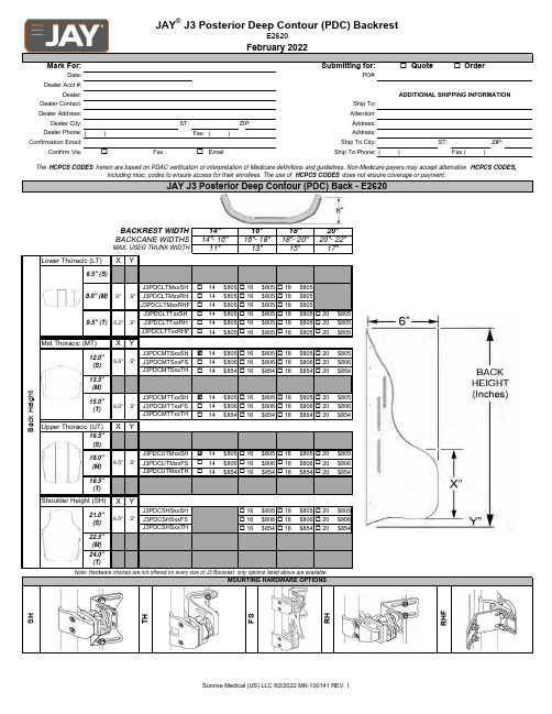
o o ST:ZIP:()Fax:()ST:ZIP:o o()Fax:()Lower Thoracic (LT)X Yo 14$805o 16$805o 18$805o 14$805o 16$805o 18$805o 14$805o 16$805o 18$805o 14$805o 16$805o 18$805o20$805o14$805o 16$805o18$805o 20$805o14$805o 16$805o 18$805o 20$805Mid Thoracic (MT)XYo 14$805o 16$805o 18$805o 20$805o 14$806o 16$806o 18$806o 20$806o14$854o 16$854o 18$854o 20$854o 14$805o 16$805o 18$805o 20$805o 14$806o 16$806o 18$806o 20$806o 14$854o 16$854o 18$854o 20$854Upper Thoracic (UT)X Yo 14$805o 16$805o 18$805o 20$805o 14$806o 16$806o 18$806o 20$806o 14$854o 16$854o 18$854o 20$854Shoulder Height (SH)XYo 16$805o 18$805o 20$805o 16$806o 18$806o 20$806o 16$854o 18$854o 20$854R H FB a c k H e i g h tNote:Hardware choices are not offered on every size of J3Backrest,only options listed above are available.J3PDCLTMxxRHJ3PDCLTTxxRHF12.0"(S)J3PDCSHSxxFS J3PDCSHSxxTH S HT HF S24.0"(T)22.5"(M)R H.5"J3PDCSHSxxSH J3PDCMTSxxFS J3PDCMTTxxFS MOUNTING HARDWARE OPTIONS19.5"(T)21.0"(S) 6.5"5.5".5"J3PDCMTSxxSH J3PDCMTTxxTH 16.5"(S)15.0"(T)6.5".5"J3PDCUTMxxFS J3PDCUTMxxTH J3PDCMTSxxTH 13.5"(M)18.0"(M) 6.5".5"J3PDCUTMxxSH J3PDCLTMxxSH J3PDCLTMxxRHFJ3PDCLTTxxSH J3PDCLTTxxRH J3PDCMTTxxSH 16"18"20"BACKCANE WIDTHS14"-16"16"-18"18"-20"8.0"(M)9.5"(T)20"-22"ER TRUNK WIDTH 11"13"15"17"6.5"(S)5".5"5.2".5"The HCPCS CODES herein are based on PDAC verification or interpretation of Medicare definitions and guidelines.Non-Medicare payers may accept alternative HCPCS CODES,including misc.codes to ensure access for their enrollees.The use of HCPCS CODES does not ensure coverage or payment.Dealer Phone:Address:Confirmation Email:Ship To City:JAY ®J3Posterior Deep Contour (PDC)BackrestE2620February 2022Mark For:Submitting for:Quote OrderADDITIONAL SHIPPING INFORMATIONDealer:Date:PO#:Dealer Acct #:Dealer Contact:Ship To:Confirm Via:FaxEmailShip To Phone:Dealer Address:Attention:Dealer City:Address:JAY J3Posterior Deep Contour (PDC)Back -E2620BACKREST WIDTH 14"oo a a o o o o ooo o o o o o o o o o ooooJ3CPLUMD-MediumC-PlushPadAAPM HUPMJ3CRDLLG-LrgContourCradle Pad E0955HUPS$333.00PL E0955AAPN J3PLSH10-10"Plush Pad J3PLSH14-14"Plush Pad E09551410Example =J3HEDX14=$166.00$154.00J3UHMK0108Completed JAY J3Headrest #$166.00J3CPLULG -Large C-Plush Pad E0955STEP 1-Headrest Post Example =J3HEDXContour Cradle C-PlushAdjust-A-PlushHeads Up PM$166.00$333.00E0955CM J3PLSH8-8"Plush PadE0955J3AAPS -Adjust-A-Plush Standard (Lg)$173.00$173.00$186.00E0955$279.00$333.00E0955J3CRDLMD -Med Contour Cradle Pad J3AAPN -Adjust-A-Plush Narrow (Sm)$279.00J3HUPM -HeadsUp Med:4.1"Sht Arms E0955J3AAPS -Adjust-A-Plush Medium J3HUPL -HeadsUp Lrg:5.3"Lng Arms AAPS CL $279.00JAY J3Back AccessoriesAll JAY J3Back accessories are optional.All accessories will be factory mounted as much as possible to insure proper shipping (If selected below).SHIPPING INSTRUCTIONSOption #HCPCS DefinitionN/AShip Back on Chair (Chair to be ordered separately)STEP 1Select your HEADREST POSTN/A HeadrestsPlease select one box from the below Headrest Mount &Bracket choices.Use this section for selecting headrest.Head supports are not available on LT Back ShellsDefinitionPrice Price Option #HCPCS N/CShip accessories mounted on back N/C$215.00$301.00E1028$376.00ONYX Mount &Bracket Cobra Mount &BracketPlease select one box from the below Headrest Pad choices.E1028Axys Mount &Bracket $236.00J3HEDC J3HEDX L I N XJ3HEDL J3HEDO LINX Mount &Bracket E1028J3HEDFCobra Flip Back Mount and Bracket$301.00J3HEDL2E1028LINX 2Mount &Bracket$333.00C O B R A F l i p b a c kE1028STEP 2Select your HEADREST PADE1028C O B R AA X Y SO N Y XL I N X2Universal Headrest Mounting Plate Only$56.00UNIVERSAL MOUNTING PLATEJ3HUPS -HeadsUp Sml:3.5"Sht ArmsE0955E0955PLUSHSTEP 2-Headrest Pad #Example =14+E0955E09558HUPLo o o o ooo o o o o o o o o o o o JLAT6X6E0956LATERAL 6"Depth X 6"Height $135.00JLAT6X6E0956Lateral 6"Depth X 6"Height $135.00Lateral Swing Away Mount -Right$283.00JSAMNTLE1028Lateral Swing Away Mount -Left$283.00JSAMNTRE1028LAT 6X5W/S/A MOUNTS -RH$418.00JLATSA66LLAT 6X6W/S/A MOUNTS -LH$418.00JLATSA66RJLATSA65LLAT 6X5W/S/A MOUNTS -LH$418.00JLATSA65RLAT 6X6W/S/A MOUNTS -RH$418.00JLAT6X5E0956LATERAL 6"Depth X 5"Height $135.00JLAT6X5E0956JSAMNTLE1028Lateral 6"Depth X 4"Height $135.00JSAMNTLE1028Lateral Swing Away Mount -Left$283.00JSAMNTRE1028Lateral Swing Away Mount -Right$283.00JLAT6X4E0956LATERAL 6"Depth X 4"Height $135.00JLAT6X4E0956Lateral Swing Away Mount -Right$283.00JSAMNTLE1028Lateral Swing Away Mount -Left$283.00JSAMNTRE1028JSAMNTRLE1028Lateral Swing Away Mount -Left$283.00JSAMNTRE1028Lateral Swing Away Mount -Right$283.00JLATSA46LLAT 4X6W/S/A MOUNTS -LH$418.00JLATSA46RLAT 4X6W/S/A MOUNTS -RH$418.00JLAT4X5E0956LATERAL 4"Depth X 5"Height $135.00JLAT4X5E0956Lateral 4"Depth X 5"Height $135.00JLATSA45LLAT 4X5W/S/A MOUNTS -LH$418.00JLATSA45RJSAMNTLE1028Lateral Swing Away Mount -Left$283.00JSAMNTRE1028Lateral Swing Away Mount -Right$283.00LAT 4X5W/S/A MOUNTS -RH$418.00Swing-Away Lateral Thoracic SupportLeft SideRight SideJLAT4X4E0956Lateral 4"Depth X 4"Height $135.00JLAT4X4E0956Lateral 4"Depth X 4"Height $135.00Includes:Swing-away mounting hardware,left and right lateral are independent.Different types and sizes can be selected for each side.JLATSA44LLAT 4X4W/S/A MOUNTS -LH$418.00JLATSA44RLAT 4X4W/S/A MOUNTS -RH$418.00J3LAT4X5FX E0956LATERAL 4"Depth X 5"Height FIXED $269.00J3LAT6X5FX E0956LATERAL 6"Depth X 5"Height FIXED $269.00J3LAT4x6FXE0956LATERAL 4"Depth X 6"Height FIXED$269.00J3LAT6X6FXE0956LATERAL 6"Depth X 6"Height FIXED$269.00Lateral SupportsUse this section for selecting laterals and teral supports are not available on Lower Thoracic Back ShellsLateral Thoracic Support (Fixed)Includes fixed mounting teral pads use 3DX covers with 1/2"Sunmate foam in the coreJ3LAT4X4FX E0956LATERAL 4"Depth X 4"Height FIXED $269.00J3LAT6X4FX E0956LATERAL 6"Depth X 4"Height FIXED $269.00Lateral Swing Away Mount -Left$283.00JSAMNTRE1028Lateral Swing Away Mount -Right$283.00JLAT4X6E0956LATERAL 4"Depth X 6"Height $135.00JLAT4X6E0956Lateral 4"Depth X 6"Height $135.00Lateral 6"Depth X 5"Height $135.00JLATSA64LLAT 6X4W/S/A MOUNTS -LH$418.00JLATSA64RLAT 6X4W/S/A MOUNTS -RH$418.00o o oo o oo o o o o o o o o o o o o o o o ooA BC D E F G H ABC D E F G H ABC S 15" 4.5"2"9"4"4"2"8.5"S 15" 4.5"2"9"1"4"2"8.5"S 12.3"9" 6.5"M 19" 5.5"2"11"5"5"3"9.5"M 18.5"5.5"2"11"1"5" 2.5"9.5"M 14.3"11"9.8"L22.5"6.5"2"13"6"6" 3.5"10.5"L22.5"6.5"2"13" 1.5"6" 3.5"10.5"L15.5"11.5"9.8"XL 25.5"6.5" 2.5"14"7"7"4.5"11.5"XL 25.5"6.5" 2.5"14" 1.5"7"4.5"11.5"XL 17.5"12.8"10"oo o o o oooINNER COVERTo order a optional inner cover enter a additional line item by adding "IC"to the front of your desired J3back part number and remove your hardware suffix.Add "IC"K0108Inner Cover$135.0020"to 22"Wide$48.00117098K010816"to 18"Wide$48.00117097K010814"to 16"Wide $48.00117100K0108VANITY FLAP117096K010812"to 14"Wide $48.00117099K010818"to 20"Wide $48.00GUIDE BRACKETS &HARDWARE ONLYJ3GPSGK0108Guide Brackets Only -Pair$44.00J3HHPK0108Hardware Pack Only$21.00Classic StyleContour Style Center-Opening with BucklePadded Anterior Trunk Straps (Lrg)$152.00J3HRNCSXE0960Classic-Structured Pull Down (X-Lrg)$163.00J3HRNPSXE0960Padded Anterior Trunk Straps (X-Lrg)$152.00J3HRNCSL E0960Classic-Structured Pull Down (Lrg)$163.00J3HRNPSL E0960Padded Anterior Trunk Straps (Sml)$152.00J3HRNCSM E0960Classic-Structured Pull Down (Med)$163.00J3HRNPSM E0960Padded Anterior Trunk Straps (Med)$152.00J3HRNCSS E0960Classic-Structured Pull Down (Sml)$163.00J3HRNPSS E0960Contoured-Structured Pull Down (Lrg)$163.00J3HRNCDX E0960Classic-Dynamic Pull Down (X-Lrg)$163.00J3HRNTSX E0960Contoured-Structured Pull Down (X-Lrg)$163.00J3HRNCDL E0960Classic-Dynamic Pull Down (Lrg)$163.00J3HRNTSL E0960Contoured-Structured Pull Down (Sml)$163.00J3HRNCDM E0960Classic-Dynamic Pull Down (Med)$163.00J3HRNTSM E0960Contoured-Structured Pull Down (Med)$163.00J3HRNCDS E0960Classic-Dynamic Pull Down (Sml)$163.00J3HRNTSS E0960Contoured-Dynamic Pull Down (Lrg)$163.00J3HRNCOX E0960Center Opening w/Buckle (X-Lrg)$163.00J3HRNTDX E0960Contoured-Dynamic Pull Down (X-Lrg)$163.00J3HRNCOL E0960Center Opening w/Buckle (Lrg)$163.00J3HRNTDL E0960Chest Straps,Harnesses and BracketsUse this section for selecting harnesses.Harnesses are not available on Lower Thoracic Back ShellsCHEST STRAPS &HARNESSES (Includes strap guides &mounting hardware)Contoured-Dynamic Pull Down (Sml)$163.00J3HRNCOM E0960Center Opening w/Buckle (Med)$163.00J3HRNTDM E0960Contoured-Dynamic Pull Down (Med)$163.00J3HRNCOS E0960Center Opening w/Buckle (Sml)$163.00J3HRNTDS E0960。
催化剂的历史及其发展趋势1.催化剂的历史催化现象由来已久,早在古代,人们就利用酵素酿酒制醋,中世纪炼金术士用硝石催化剂从事硫磺制作硫酸。
十三世纪发现硫酸能使乙醇产生乙醚,十八世纪利用氧化氮之所硫酸,即所谓的铅室法[1]。
最早记载“催化现象”的资料可以追溯到十六世纪末(1597年)德国的《炼金术》一书,但是当时“催化作用”还没有被作为一个正式的化学概念提出。
一直到十九世纪初期,由于催化现象的不断发现,为了要解释众多的催化现象,开始提出了“催化”这一个名词。
最早是在1835年,瑞典化学家J.J.Berzelius(1779-1848)在其著名的“二元学说”的基础上,把观察到的零星化学变化归结为是由一种“催化力(catalyticforce)”所引起的,并引入了“催化作用(cataysis)”一词[2]。
从此,对于催化作用的研究才广泛的开展起来。
1.1萌芽时期(20世纪以前)催化剂工业发展史与工业催化过程的开发及演变有密切关系。
1740年英国医生J.沃德在伦敦附近建立了一座燃烧硫磺和硝石制硫酸的工厂,接着,1746 年英国J.罗巴克建立了铅室反应器,生产过程中由硝石产生的氧化氮实际上是一种气态的催化剂,这是利用催化技术从事工业规模生产的开端。
1831年P.菲利普斯获得二氧化硫在铂上氧化成三氧化硫的英国专利。
19世纪60年代,开发了用氯化铜为催化剂使氯化氢进行氧化以制取氯气的迪肯过程。
1875年德国人E.雅各布在克罗伊茨纳赫建立了第一座生产发烟硫酸的接触法装置,并制造所需的铂催化剂,这是固体工业催化剂的先驱。
铂是第一个工业催化剂,现在铂仍然是许多重要工业催化剂中的催化活性组分。
19世纪,催化剂工业的产品品种少,都采用手工作坊的生产方式。
由于催化剂在化工生产中的重要作用,自工业催化剂问世以来,其制造方法就被视为秘密。
1.2奠基时期(20世纪初)在这一时期内,制成了一系列重要的金属催化剂,催化活性成分由金属扩大到氧化物,液体酸催化剂的使用规模扩大。
P/N: 1802051030012 *1802051030012*MGate 5103 Series Quick Installation GuideVersion 1.3, January 2021Technical Support Contact Information/support2021 Moxa Inc. All rights reserved.OverviewThe MGate 5103 is an industrial Ethernet gateway for ModbusRTU/ASCII/TCP, EtherNet/IP, and PROFINET network communications. Package ChecklistBefore installing the MGate 5103, verify that the package contains the following items:• 1 MGate 5103 gateway• 1 serial cable: CBL-RJ45F9-150•Quick installation guide (printed)•Warranty cardPlease notify your sales representative if any of the above items is missing or damaged.Optional Accessories (can be purchased separately)•CBL-F9M9-150: DB9-female-to-DB9-male serial cable, 150 cm •CBL-F9M9-20: DB9-female-to-DB9-male serial cable, 20 cm •CBL-RJ45SF9-150: RJ45-to-DB9-female shielded serial cable, 150 cm•ADP-RJ458P-DB9F: DB9-female-to-RJ45 connector•ADP-RJ458P-DB9F-ABC01: DB9-female-to-RJ45 connector •Mini DB9F-to-TB: DB9-female-to-terminal-block connectorHardware IntroductionLED IndicatorsLED Color DescriptionReady Off Power is off or a fault condition existsGreen Steady: Power is on, and the MGate isfunctioning normallyRed Steady: Power is on, and the MGate is bootingupBlinking slowly: Indicates an IP conflict, or theDHCP or BOOTP server is not respondingproperlyFlashing quickly: the microSD card failedMB/EIP Off Modbus: No communication with Modbus deviceEtherNet/IP: No I/O data exchangeGreen (Blinking) Modbus: Communication in progress EtherNet/IP: I/O data is exchangingRed (Blinking) Communication errorWhen MGate 5103 acts as ModbusClient/Master:1. Slave device returned an error (exception)2. Received a frame error (parity error, checksum error)3. Timeout (slave device is not responding or TCP connection timed out)When MGate 5103 acts as ModbusServer/Slave:1. Received invalid function code2. Master accessed invalid register address or coil addresses3. Received frame error (parity error, checksum error)When MGate 5103 acts as EtherNet/IP adapter: 1.Refuses connection due to incorrectconfigurationPN Off No connection with PROFINET I/O controllerGreen (Blinking) PROFINET I/O is connected and the controller is in RUN modeRed (Blinking) PROFINET I/O is connected, but the controller is in STOP modeDimensionsUnit: mm (inch)Reset ButtonRestore the MGate to factory default settings by using a pointed object (such as a straightened paper clip) to hold the reset button down until the Ready LED stops blinking (approximately five seconds).Pull-up, Pull-down, and Terminator for RS-485Beneath the MGate 5103’s top cover, you will find DIP switches to adjust each serial port’s pull-up resistor, pull-down resistor, and terminator.SW1 2 3 Pull-upresistorPull-downresistorTerminatorON 1 kΩ 1 kΩ120 ΩOFF 150 kΩ* 150 kΩ* –**DefaultHardware Installation Procedure1.Connect the power adapter. Connect the 12-48 VDC power line orDIN-rail power supply to the MGate 5103’s terminal block.e a serial cable to connect the MGate to the Modbus device.e an Ethernet cable to connect the MGate to the PROFINET IOcontroller.4.The MGate 5103 is designed to be attached to a DIN rail or mountedon a wall. For DIN-rail mounting, push down the spring and properly attach it to the DIN rail until it “snaps” into place. For wall mounting, install the wall-mounting kit (optional) first and then screw the device onto the wall.The following figure illustrates the two mounting options:Software Installation InformationPlease download the user's manual and Device Search Utility (DSU) from Moxa’s website: Refer to the user’s manual for additional details on using the DSU. The MGate 5103 also supports login via a web browser. Default IP address: 192.168.127.254 Default account: admin Default password: moxaPin AssignmentsModbus Serial Port (Male DB9) PinRS-232RS-422/ RS-485 (4W)RS-485 (2W) 1 DCD TxD-(A) – 2 RXD TxD+(B) –3 TXD RxD+(B)Data+(B) 4 DTR RxD-(A) Data-(A) 5* GND GND GND 6 DSR – – 7 RTS – – 8 CTS – – 9 – ––*Signal groundEthernet Port (RJ45) Pin Signal 1 Tx+ 2 Tx- 3 Rx+ 6Rx-Power Input and Relay Output PinoutsV2+V2-V1+V1-ShieldedGroundDC Power Input 2 DCPowerInput 2 N.O.CommonN.C.DC Power Input 1 DC Power Input 1SpecificationsPower Requirements Power Input12 to 48 VDC Power Consumption 455 mA max.Operating TemperatureStandard models:0 to 60°C (32 to 140°F) Wide temp. models:-40 to 75°C (-40 to 167°F)Ambient Relative Humidity 5 to 95% RH Dimensions 36 x 105 x 140 mm (1.42 x 4.13 x 5.51 in) Reliability Alert Tools Built-in buzzer and RTC MTBF 1,140,815 hrs.1. DEMKO Certification number: 13 ATEX 1307610XIEC Certification Number: IECEx UL 13.0051X; 2. Ambient Temperature Range:0°C to 60°C (for models without suffix –T) -40°C to 75°C (for models with suffix –T only) 3. Certification String: Ex nA nC IIC T3 Gc4. Standards Covered: EN 60079-0:2013+A11/IEC 60079-0 6th Ed.AND EN 60079-15:2010/IEC 60079-15 4th Ed. 5. The conditions of safe use:a. Ethernet Communications Devices are intended for mounting in atool-accessible IP54 enclosure and use in an area of not more than pollution degree 2 as defined by IEC/EN 60664-1.b. Conductors suitable for use in an ambient temperature greaterthan 86°C must be used for the power supply terminal. c. A 4mm 2 conductor must be used when a connection to theexternal grounding screw is utilized.d. Provisions shall be made, either in the equipment or external tothe equipment, to prevent the rated voltage from being exceeded by the transient disturbances of more than 140% of the peak-rated voltage.Terminal block (plug matched with socket): rated at 300 V, 15 A, 105°C, 12-28 AWG (0.0804 mm2 to 3.31 mm2) wire size, torque value 4.5 lb-in (0.509 N-m). The input terminal cable size: 14 AWG (2.1 mm2).NOTE This equipment is suitable for use in Class 1, Division 2, Groups A, B, C, D or nonhazardous locations only.Moxa Inc.No. 1111, Heping Rd., Bade Dist., Taoyuan City 334004, Taiwan。
低温SCR脱硝催化剂综述高翔;卢徐节;胡明华【摘要】目前氮氧化物(NOx)的污染越来越严重,低温选择性催化还原法(SCR)脱硝催化技术作为新型的、具有潜力的烟气脱硝技术,备受人们关注。
综述了低温SCR脱硝催化剂的的研究现状,着重介绍了锰基催化剂、钒基催化剂以及其他金属氧化物催化剂的研究进展,阐述了不同种类的催化剂制备方法、载体,以及使用不同种类的金属氧化物活性组分对催化剂活性和脱硝效率的影响,探讨了低温SCR催化剂的脱硝机理,同时介绍了烟气中水蒸气和SO2对催化过程的影响。
%Nowadays,NOx pollution becomes more and more serious ,low temperature SCR denitra-tion technology,as a kind of new and potential denitration technology,has attract people′s attention. Gives a summary and commentary on the research status of low temperature SCR denitration catalysts and mainly introduces the scientific research status of manganese catalysts,vanadium cata-lysts and other metal oxide catalysts. Indicates the different types of catalyst preparation methods, carriers,and the use of different kinds of metal oxides may all have influence on the catalyst activity and the efficiency of denitrification. Meanwhile,the denitration mechanism of low-temperature SCR catalysts is introduced. At last ,elaborates the effects of water vapor and SO2 in fuel gas on catalytic process.【期刊名称】《江汉大学学报(自然科学版)》【年(卷),期】2014(000)002【总页数】7页(P12-18)【关键词】氮氧化物(NOx);低温SCR脱硝催化剂;脱硝机理;金属氧化物【作者】高翔;卢徐节;胡明华【作者单位】工业烟尘污染控制湖北省重点实验室(江汉大学),江汉大学化学与环境工程学院,湖北武汉430056;工业烟尘污染控制湖北省重点实验室(江汉大学),江汉大学化学与环境工程学院,湖北武汉 430056;工业烟尘污染控制湖北省重点实验室(江汉大学),江汉大学化学与环境工程学院,湖北武汉 430056【正文语种】中文【中图分类】X701.70 引言近年来,我国经济发展迅速,能源的消耗量越来越大。