宁波斐士电机
- 格式:pdf
- 大小:3.26 MB
- 文档页数:44
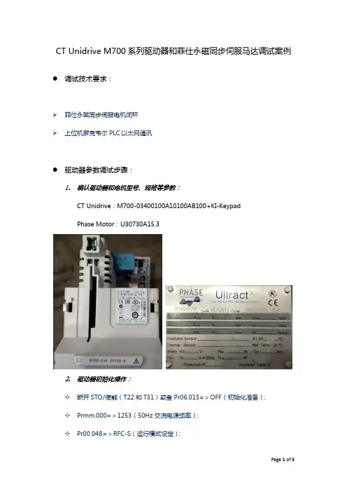
CT Unidrive M700系列驱动器和菲仕永磁同步伺服马达调试案例●调试技术要求:➢菲仕永磁同步伺服电机闭环➢上位机罗克韦尔PLC以太网通讯●驱动器参数调试步骤:1.确认驱动器和电机型号、规格等参数:CT Unidrive:M700-03400100A10100AB100+KI-KeypadPhase Motor:U30730A15.32.驱动器初始化操作:✧断开STO/使能(T22和T31)或者Pr06.015=>OFF(初始化准备);✧Prmm.000=>1253(50Hz交流电源频率);✧Pr00.048=>RFC-S(运行模式设定);✧按下红色复位按键(初始化完成)。
✧接通STO/使能(T22和T31)或者Pr06.015=>ON(驱动器使能待机)3.更改用户安全级别/访问级别:✧Pr00.049=>1(所有菜单均允许编辑)4.编码器相关接线和参数设定:✧菲仕电机编码器为绝对型,和CT驱动器完美兼容,接线图如下图所示:✧Pr03.024=>0(RFC反馈模式:Feedback);✧Pr03.026=>0(电机控制反馈选择:P1 Drive);✧Pr03.034=>2500(P1每转旋转脉冲数:2500PPR);✧Pr03.036=>0(P1电源电压:5V);✧Pr03.038=>3(P1设备类型:AB Servo);✧Pr03.039=>1(P1终端选择:AB启用,Z不启用);✧Pr03.118=>1(P1热敏电阻类型:KTY84)。
5.电机参数设定和参数自调谐:✧Pr05.007=>7.4(额定电流:7.4A);✧Pr05.008=>1500(额定转速:1500RPM);✧Pr05.009=>362(额定转速:1500RPM);✧Pr05.011=>8(电机极数:8Poles);✧Pr05.033=>224(每1000转电压:224V/1000RPM);✧Pr05.012=>2(电机自调谐方式:ROTATING,※电机旋转自调谐务必保证电机光轴,无负载输出);✧Pr01.014=>4(给定选择器:Keypad);✧按下键盘绿色运行按键,键盘显示Auto Tune,电机旋转自调谐,如果自调谐成功完成,键盘显示Inhibit。
菲仕伺服电机原理一、产品简介菲仕伺服电机与国内外同类产品相比具有很高的力矩/体积和功率比,低速时具有最好的稳定性,从面克服机械传动装置的诸多限制,使众多的应用场合采用直接驱动技术,满足高端机械设备对精度、速度和效率的要求,满足了用户对节能和环保的苛刻要求。
菲仕系列产品,设计额定力矩从1N.M到10000N.M,额定功率从100W到5MW,将势必成为中国功率规格系列最全的高性能伺服系统产品,并可以直接和全面地取代进口伺服系统产品。
二、电机产品系列化定型研制工艺流程三、工作原理交流伺服电动机在没有控制电压时,伺服电机内部的转子是永磁铁,驱动器控制的U/V/W三相电在定子内绕组形成电磁场,转子在此磁场的作用下转动,同时电机自带的编码器反馈信号给驱动器,驱动器根据反馈值与目标值进行比较,调整转子转动的角度。
四、设计参数的选取及设备结构伺服电机主要由定子铁芯及绕组、永磁体转子模块、高精度轴承及轴承支架、电气插头及接线盒等附件组成,如下图所示:1、定子铁芯1)、矽钢冲片采用高速冲床进行,冲片和叠片在冲压过程中一次完成,大大的提高了生产效率。
高速冲片代替以往的粉末冶金制造铁芯使铁芯的电磁特性不再受粉末成分和烧结条件的影响,使铁芯的电磁特性得以稳定。
在组装和总装过程中也不会因操作不慎而使铁芯缺角少肉而影响质量,使操作过程得以简化;2)、我们对比了高速冲片与低速冲片对电机的性能的影响,数据表明高速冲片制作的铁芯,电机的漏磁及涡流损耗大大减少,电机整体发热量大大降低,故选用了从英国进口过来的高速冲床及长寿命模具,来保证矽钢冲片的稳定性及低损耗性。
3)、我们对比了0。
5MM高速冲片与0。
3MM高速冲片对电机的性能的影响,数据表明0。
3MM高速冲片制作的电机的漏磁及涡流损耗更进一步减少,电机整体发热量也进一步降低,故选用了0。
3MM矽钢片的模具。
2、定子绕组电机所采用的力矩绕组设计是一种具有特殊Ke和Kt常数的绕组,可适用于无齿轮传动的低速场合和直接驱动。

AX-V 全数字交流伺服驱动器用户手册宁波菲仕电机技术有限公司版本号:AXV-SPDV-1-0序言感谢您购买宁波菲仕电机技术有限公司的菲仕AX-V全数字交流伺服驱动器(以下简称驱动器)产品。
AX-V系列伺服驱动器是针对交流永磁伺服电机控制用的高品质、多功能、低噪音的伺服驱动器,可对伺服电机实现速度、力矩和位置高精度、高响应的控制。
AX-V系列伺服驱动器为您提供了丰富而又强大的功能:✧可以通过RS-485、CanOpen总线、ProfiBus总线与上位控制器通信,驱动器的所有参数和指令均可以通过上位控制器以通信的方式传送给驱动器。
✧通过Intradrive总线可以使驱动器与驱动器之间实现高速的通信,在需要多个驱动器联动的场合更具有优越性。
✧可以适配多种编码器,具体的有正余弦编码器、光电增量式编码器、旋转变压器、绝对值式编码器等,并都能使电机获得相当的控制性能。
✧AX-V系列驱动器具有可编程功能,允许用户对伺服驱动器进行程序开发,并且有8个数字量输入点、8个数字量输出点、3个模拟量输入口、4个模拟量输出口供用户编程使用,具有很大的灵活性。
而且,用户可以根据实际工作场合要求开发适合于自己使用的应用工程软件。
✧我公司为用户提供了速度、位置控制标准应用工程软件,可以满足大多数控制场合的使用要求。
在使用AX-V系列驱动器之前,请仔细阅读本手册,以保证正确使用。
错误的操作和使用可能造成驱动器运行不正常、发生故障或者降低使用寿命,并有可能造成驱动器损坏、人身伤害等事故。
因此使用前应反复阅读本手册,并严格按照操作说明使用。
本手册为驱动器的随机附件,务必请您使用后妥善保管,以备今后对驱动器进行检修和维护时使用。
第一章注意事项1.1 开箱检查......................................P3 1.2 驱动器的型号说明..............................P3 1.3 安全注意事项..................................P3 1.3.1 安装注意事项................................P4 1.3.2 接线注意事项................................P4 1.3.3 维护注意事项................................P5 1.3.4 使用注意事项................................P5 1.3.5 报废时注意事项..............................P51.1 开箱检查在开箱时,请认真确认下列各项:在运输途中是否有破损现象驱动器型号是否与您的订货要求相一致附件是否齐全,包装箱内装有如下器件:●驱动器一台●驱动器接线端子排三个●25芯编码器插头一个●用户手册一套如发现有不符合或者遗漏的情况,请立即与我公司联系!1.2驱动器的型号说明AX-V1.3安全注意事项危险:如果没有按照要求进行操作,可能会造成设备的严重损坏或者人员的伤害。
宁波菲仕运动控制技术有限公司宁波菲仕电机技术有限公司永磁交流伺服电机Ultract III(第二版)使用说明书目录一、概述 (3)二、规范说明 (3)三、检查 (3)四、安装 (4)五、编码器配置 (4)六、接线 (6)七、PHASE电机与驱动器接线 (10)Ⅰ、匹配PHASE驱动器接线 (10)(1)、配置正余弦编码器接线 (10)(2)、配置绝对值编码器接线 (11)(3)、配置旋转变压器接线 (12)Ⅱ、匹配LENZE驱动器接线 (13)(1)、配置旋转变压器接线 (13)(2)、配置绝对值编码器接线 (14)(3)、配置数字增量式编码器接线 (15)Ⅲ、匹配KEB驱动器接线 (16)(1)、配置正余弦编码器接线 (16)(2)、配置旋转变压器接线 (17)(3)、配置绝对值编码器接线 (18)Ⅳ、匹配SIEMENS驱动器接线 (19)(1)、配置正余弦编码器接线 (19)(2)、配置旋转变压器接线 (20)Ⅴ、匹配Schneider驱动器接线 (21)(1)、配置旋转变压器接线 (21)(2/3)、配置绝对值编码器接线 (22)Ⅵ、匹配B&R驱动器接线 (24)(1)、配置绝对值编码器接线 (24)Ⅶ、匹配CT驱动器接线 (25)(1)、配置绝对值编码器接线 (25)Ⅷ、匹配Kinwaytech(御能)驱动器接线 (26)(1)、配置旋转变压器接线 (26)Ⅸ、匹配Inovance(汇川)、Modrol(蒙德)驱动器接线 (27)(1)、配置旋转变压器接线 (27)Ⅹ、匹配Vector(威科达)驱动器接线 (28)(1)、配置数字增量式编码器 (28)八、运行与维护 (29)衷心感谢您选用菲仕伺服电机,为使本电机一直维持良好的运行状态,请将本手册随整机附送给最终用户。
虽然在您的选型过程中,可能已经对本产品有所了解并与本公司的技术人员进行了某些沟通,但为充分发挥本电机最佳功能,仍请在使用前,仔细阅读本使用说明书,必要时请与PHASE的有关人员联系,获得必要的帮助,以便正确的使用和维护电机,使之运行可靠,经久耐用。

马克·文特里(Marco Venturini):现任宁波菲仕电机技术有限公司首席科学家顾问,2015年获得浙江省人民政府“西湖友谊奖”, 2016年获得中国政府友谊奖
曾看到外国学者这样描述中国的发展:“近30年来最震撼世界的国家无疑是中国,中国社会经济实现了前所未有的大突破、大跨越和大发展,可以说,世界各国都强烈感受到了中国社会经济和人民生活发生的巨变。
”
改革开放以来,中国的经济、政治、文化、社会、国际地位等各个领域都发生了翻天覆地的变化。
在短短40年间,中国走过了西方发达国家上百年走过的道路,实现了从贫困落后到繁荣发展、从农业大国到工业大国、从计划经济到市场经济、从封闭孤立到全球交往的历史性转变,并以崭新的面貌屹立于国际社会。
6国际人才交流2018·4。
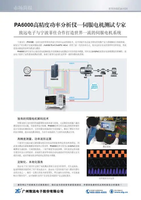
请您用以下的联系方式联系我们,我们会为您安排专家现场测试,并提供免费样机试用和报告分析服务! 更多详情请访问PA6000高精度功率分析仪—伺服电机测试专家 致远电子与宁波菲仕合作打造世界一流的伺服电机系统宁波菲仕(PHASE )全面引进世界领先的意大利菲仕运动控制技术,是中国最早也是最为领先的伺服产品与系统解决方案提供商。
研发生产的全数字交流伺服驱动器(AxM35.70.4和AxM70.140.4)采用了新一代的冷却方式,要求达到非常高的效率和功率密度,因此需更高精度的功率仪器进行测量。
PA6000功率分析仪以独有的电机解码技术有效解决电机测试不同步的技术难题,同时高达0.02%精度保证电参数测量的准确性。
致远电子提供了高性能电机测试仪器,协助宁波菲仕成功打造世界一流的伺服电机系统。
独有的伺服电机解码技术伺服电机行业内使用传感器测量电机转速与扭矩,无法解决电机输入输出测量值同步的问题,导致效率值不精确。
PA6000功率分析仪通过独特的软硬件设计实现电机解码技术,支持伺服电机编码信号直接输入,解决了测量不同步的技术难题,提高电机测量精度,为菲仕电机提供了完善的电机测试方案。
高精度测量、功率波形运算宁波菲仕交流永磁无刷伺服电机具有很高的转矩/体积比和功率/体积比,因此要求测试仪器精确测量转矩和计算功率。
PA6000功率分析仪以0.02%精度精确测量失速扭矩、空载绕组阻抗、三相平衡度等电机参数,同时波形运算功能实现实时显示功率波形、直接损失波形和电机启动电流波形等常规仪器无法实现的功能,成功突破电机功率波形运算的技术难题。
定制化、本地化服务致远电子为宁波菲仕定制了电机测试系统专业化分析软件,其生成曲线、报表和数据功能得到了用户的高度认可。
致远电子是国内最早进入测量仪器行业的企业之一,拥有一支强大的技术研发团队,网点遍布全国各地,不仅极速响应并服务用户,还可根据行业用户差异化需求提供产品定制化服务。
功率波形实时运算测试现场。
宁波菲仕运动控制技术有限公司宁波菲仕电机技术有限公司永磁交流伺服电机Ultract III(第二版)使用说明书目录一、概述 (3)二、规范说明 (3)三、检查 (3)四、安装 (4)五、编码器配置 (4)六、接线 (6)七、PHASE电机与驱动器接线 (10)Ⅰ、匹配PHASE驱动器接线 (10)(1)、配置正余弦编码器接线 (10)(2)、配置绝对值编码器接线 (11)(3)、配置旋转变压器接线 (12)Ⅱ、匹配LENZE驱动器接线 (13)(1)、配置旋转变压器接线 (13)(2)、配置绝对值编码器接线 (14)(3)、配置数字增量式编码器接线 (15)Ⅲ、匹配KEB驱动器接线 (16)(1)、配置正余弦编码器接线 (16)(2)、配置旋转变压器接线 (17)(3)、配置绝对值编码器接线 (18)Ⅳ、匹配SIEMENS驱动器接线 (19)(1)、配置正余弦编码器接线 (19)(2)、配置旋转变压器接线 (20)Ⅴ、匹配Schneider驱动器接线 (21)(1)、配置旋转变压器接线 (21)(2/3)、配置绝对值编码器接线 (22)Ⅵ、匹配B&R驱动器接线 (24)(1)、配置绝对值编码器接线 (24)Ⅶ、匹配CT驱动器接线 (25)(1)、配置绝对值编码器接线 (25)Ⅷ、匹配Kinwaytech(御能)驱动器接线 (26)(1)、配置旋转变压器接线 (26)Ⅸ、匹配Inovance(汇川)、Modrol(蒙德)驱动器接线 (27)(1)、配置旋转变压器接线 (27)Ⅹ、匹配Vector(威科达)驱动器接线 (28)(1)、配置数字增量式编码器 (28)八、运行与维护 (29)衷心感谢您选用菲仕伺服电机,为使本电机一直维持良好的运行状态,请将本手册随整机附送给最终用户。
虽然在您的选型过程中,可能已经对本产品有所了解并与本公司的技术人员进行了某些沟通,但为充分发挥本电机最佳功能,仍请在使用前,仔细阅读本使用说明书,必要时请与PHASE的有关人员联系,获得必要的帮助,以便正确的使用和维护电机,使之运行可靠,经久耐用。

AX-M 全数字交流伺服驱动器用户手册(位置控制)宁波菲仕电机技术有限公司版本号:AXM-POS-1-0目录序言...............................................................页第一章功能说明....................................................页1.1 POSITIONER应用工程软件说明.....................................页1.2 POSITIONER应用工程软件功能简介.................................页1.3 POSITIONER应用工程软件控制线路接线说明.........................页1.3.1 POSITIONER应用工程软件控制端子排接线说明.....................页1.3.2 POSITIONER应用工程软件总接线图...............................页第二章操作运行....................................................页2.1 运行准备.......................................................页2.1.1 必要的接线...................................................页2.1.2 接线检查.....................................................页2.1.3 COCKPIT软件的安装及功能说明..................................页2.1.4 下载POSITIONER应用工程软件到驱动器..........................页2.1.5 打开监视页面.................................................页2.2 POSITIONER应用工程软件操作说明.................................页2.2.1 零点定义过程说明.............................................页2.2.2 JOG调试方式..................................................页2.2.3 限位位置控制方式.............................................页2.2.4 位置控制方式.................................................页第三章参数说明....................................................页3.1 用户参数详细说明...............................................页3.1.1 用户参数一览表...............................................页3.1.2 用户参数详细说明.............................................页3.2 系统参数详细说明...............................................页序言感谢您购买宁波菲仕电机技术有限公司的菲仕AX-M全数字交流伺服驱动器(以下简称驱动器)产品。
U L T R A C T I I IU L T R A C T I I IS e r v o m o t oL T R A C T I I IS e r v o m o t o r i B r u s h l e s s U L T R A C T I I IIndiceIndexDescrizione generale di tipoGeneral Data . . . . . . . . . . . . . . . . . . . .5Specifiche tecniche standardSpecifications of Standard Models . . . . . . . . .6Opzioni disponibiliAvailable Options . . . . . . . . . . . . . . . . .6Protezione termica del sistemaMotor and Machine Protection . . . . . . . . . . . .7Codifica motoriMotor Order Coding . . . . . . . . . . . . . . . . .7La rivoluzione dei brushlessThe Brushless Motor Revolution . . . . . . . . . . .8Specifica freniSafety Brake Specification . . . . . . . . . . . .34Sovraccaricabilita - Condizioni ambientaliOverload rating - Thermal derating . . . . . . . .34Specifica connettoriConnectors Specification . . . . . . . . . . . . .35Fasatura encoderEncoder Phasing . . . . . . . . . . . . . . . . . .35Guida all ’applicazioneApplication Guidelines . . . . . . . . . . . . . .36Conformita motoriDeclaration of Conformity . . . . . . . . . . . . .42Specifiche tecniche Ultract III - 5Technical Data Summary Ultract III Frame Size 5Specifiche tecniche Ultract III - 7Technical Data Summary Ultract III Frame Size 7Specifiche tecniche Ultract III - 7CTechnical Data Summary Ultract III Frame Size 7CSpecifiche tecniche Ultract III - 10Technical Data Summary Ultract III Frame Size 10Specifiche tecniche Ultract III - 10FTechnical Data SummaryUltract III Frame Size 10FSpecifiche tecniche Ultract III - 10CTechnical Data SummaryUltract III Frame Size 10CSpecifiche tecniche Ultract III - 13Technical Data Summary Ultract III Frame Size 13Specifiche tecniche Ultract III - 13CTechnical Data SummaryUltract III Frame Size 13CSpecifiche tecniche Ultract III - 3Technical Data SummaryUltract III Frame Size 3Specifiche tecniche Ultract III - 16Technical Data Summary Ultract III Frame Size 16Specifiche tecniche Ultract III - 16HTechnical Data Summary Ultract III Frame Size 16Specifiche tecniche Ultract III - 13FTechnical Data SummaryUltract III Frame Size 13FServomotori Brushless ULTRACTBDescrizione generale di tipo General dataIIIBrushless Servomotors ULTRACT IIILa serie razionalestata concepitaavanguardia,per l'azionamentooperatrici a controllopassante di controllo.I servomotorirapporti dimensione/coppiagrazie al controlloassoluti,monogirotarghetta elettronica,motori(120°C),offrono una risoluzionepunti/giro,sonoregolaritàdidelle trasmissionigamma di applicazioniI servomotoripiccola dimensioneNm,per applicazioniposizionamentoapplicazionisostituzione di motori a passo e dc,fino alla grandetaglia13,in forma quadra264mm,capaci di oltre700Nm e200kW di potenza resa,per applicazioni in presadiretta su grandi linee di processo,nella prospettiva diuna progressiva eliminazione degli assi di trasmissione.Sono disponibili avvolgimenti per alimentazioni220-240V e380-440V per tutte le taglie fino alla7;per le tagliesuperiori,gli avvolgimenti standard sono tutti perimpiego380-440V.The Ultract III series of brushless servo motors was conceivedand designed as an advanced and homogeneous range of highperformance servo actuators,in line with the evolving demandsof the automation industry,and is particularly suited for directdrive applications.The Ultract III servomotors reach the highest torque/size andpower/size ratios in the industry.They are designed forsinusoidal control and embody,as standard feedback devices,optical or inductive encoders,custom designed for motoroperation,which offer absolute resolution up to8millionpoints/rev thus affording the best motion uniformity even at thelowest speed,or multiturn absolute encoders,all with serialEnDat interface and electronic nameplate.With this features,the limits of mechanical transmissions are overcome and a vastrange of applications can be transferred to direct drivetechnology.The Ultract motors range from the Size3miniature servos,starting at2Nm,which fit in a75mm square frame,formicropositioning,small components handling,DC and steppermotor replacement,to the Size13large motors,which reachto700Nm and200kW,intended for direct,distributed drive ofcontinuous process lines,in view of the progressive eliminationof long transmission shafts.Standard windings are available formany speeds and for220/240and380/460Vac for all sizes upto7.Sizes10and13windings are for380/440Vac5ProtezioneProtectionFreno di sicurezzaSafety brakeB:Coppia frenante*Tn B:Holding torque*TnConnettori Connectors Tipo industrial circolare,solo segnale,segnale+potenza Industrial circular type,signal orsignal+powerAlbero con chiavetta Keyway on shaft K(sconsigliato per applicazioni dinamiche e coninerzia del carico superiore a quella del motore)K:(not recommended especiallywhenever the load inertiaexceeds the motor inertia)PiediMounting feet B3:solo taglie10,13B3:size10,13onlySensori Sensors S:Encoder Heidenhain ERN1385sincos assolutoottico precisione20’’.N:Encoder assoluto multigiri Heidenhain EQI1327magnetico precisione1’,targhetta elettronicainterfaccia seriale ENDA T.R:Resolver2poli.S:Heidenhain ERN1385sinecosineabsolute optical encoder20”accuracyN:Absolute multiturn Heidenhain EQI1327magnetic encoder1’accuracyENDAT serial interface,electronicnameplate.R:2pole resolver.Tipo T ype Servomotori a magneti permanenti a bassainerzia ed alta rigidezza torsionaleBrushless PM AC servomotors,low inertia,high angular stiffnessCuscinetti Bearings Serie pesante,lubrificati per30,000h,bloccatoanteriormente;taglie10-13:sede frontale in ghisaHeavy duty,life lubricated;Sizes10and13:front bearing lockedin high strenght cast iron seatTipoMountingFlangiato B5Flanged B5Protezione Protection IP67IP67Concentricitàeperpendicolaritàasse/flangia Concentricity and squarenessof mounting flange Grado R(tolleranza ridotta)secondo IEC72-DIN0530Grade R(reduced tolerance)according to IEC72-DIN0530Isolamento Insulation Motore:Classe F secondo DIN0530Avvolgimento:Classe H secondo DIN0530,isolante speciale per alta frequenza per unfunzionamento affidabile anche in presenzadi riflessioni sui cavi alimentazione motoreMotor:Class F according to DIN0530Winding:Class H according to DIN0530,special high frequency winding suitablefor long wiring with high frequency PWMwaveformsOpzioni di raffreddamento Cooling Options Convezione naturale IC0041;per le taglie10e13,per cuièfrequente l'applicazione in linee di processo continuo,sono disponibili anche in versione servoventilata(opzioneF)con ventilatore asservito alla sovratemperatura eventilazione in doppia camera sopra la carcassa,conservando la protezione IP54;le taglie7,10e13sonodisponibili nelle nuove versioni C con raffreddamento adacqua e protezione IP67Natural convection IC0041;sizes10and13,designed for process lines and sustainedoperation at high speed,option F,forcedcooling over frame with fan servo controlledby the motor,overall protection grade IP54;sizes7,10and13:water cooling(option C)with IP67protectionRotore Rotor A magneti permanenti a terre rare sinterizzate,a montaggio meccanico(senza incollaggi)Syntered,high temperature rare earth,mechanically fastened magnets(without bonding)Protezione T ermicaThermal protectionIncorporata a mezzo PTC+lineare KTY84PTC+KTY84linear probeEquilibraturaBalancingGrado R(tolleranza ridotta)Grade R(reduced tolerance)Uscita Albero Shaft Liscio grado j6per montaggio a mezzo calettatore,con foro filettato coassiale;taglie3,5,7:alberouniversale con mezza chiavetta rettificataCylindrical without keyway,tolerance j6,for interference mounting with shrink rings;axial threaded hole;sizes3,5,7:universalshaft with ground half-keyPosizione di servizioWorking positionQualunque AnyCapacitàavvolgimento/terraStray capacitance to groundMinimizzata per ottimizzare le caratteristiche EMC Minimized EMC impactSensore di posizione Position sensor Sensore di posizione:Encoder Sinusoidale2048i+giro funzionante fino a120°C,che consente unarisoluzione interpolata fino a8M punti/giroSine cosine Encoder2048cycles/rev+1cycle/rev+index,operating temperatureup to120°C,allowing absoluteinterpolation to8M points/revSpecifiche tecniche standardSpecifications of standard modelsOpzioni disponibiliAvailable options ULTRA 6Codifica motoriMotor order codingCT IICodice motore Ultract IIIUltract III order codingPTC Protection Device CharacteristicsKTY Thermal Sensor, option WULKKKKKKK KKKKKKESEMPIO DI CODIFICA PER ORDINAZIONEUL 1004303N BIWØØ:Motore tipo UL 100430(40Nm,3000rpm),380vac,con encoder EQI 1327,freno di sicurezza,tenuta d’albero,KTY .ORDER CODE EXAMPLE:UL 1004303N BIWØØ:Motore type UL 100430(40Nm,3000rpm),380vac,digitalencoder EQI 1327,safety brake,lip seal,KTY .Identificativodi taglia,esprime l’altezza d’assi in cm.Taglie disponibili:-3-5-7-10-13-16.Size,(approx.shaft height in cm).Available sizes:3(motor K /75);5(motor K /100);7(motor K /145);10(motor K /200);13(motor K /264);16(motor K /340)Identificativo della coppia motore ad asse bloccato,Nm per 3,5,7;Nm*10per 10,13,16Locked rotormotor torque identifier,Nm for sizes 3,5,7;Nm*10for sizes 10,13,16Identificativo della velocitànominale,rad/s*10Nominal speed identifier,rad/s*10Identificativo della tensione di esercizio alla velocitànominale:1)220/240Vac 2)380/440Vac 3)460VacNominal voltage at nominal speed identifier:1)220/240Vac,2)380/440Vac 3)460VacIdentificativo del sensore:M :EnDat induttivo assoluto sul giro (17bit/giro)N :EnDat induttivo assolutomultigiro (4096giri+17bit/giro)S :Sincos 2048i/giro+traccia assoluta sul giro (5...16)R :Resolver 2poli Z :nessun sensoreQ:encoder assoluto multigiro,ottico,EQN1325,512p/rev ,EnDatU:encoder assoluto multigiro,ottico,EQN1325,2048p/rev ,EnDat C:encoder assoluto monogiro,ottico,EQN1313,2048p/rev ,EnDat Altri modelli disponibili su richiesta.Sensor identifier:M :EnDat inductive absolute single-turn (17bit/rev)N :EnDat inductive absolute multi-turn (4096rev +17bit/rev)S :Sincos 2048cy/rev +single turn absolute track (for motor size 5...16)R :Resolver 2poles Z :no sensorQ:Optical absolute multiturn encoder EQN 1325,512p/rev ,EnDatU:Optical absolute multiturn encoder EQN 1325,2048p/rev ,EnDat C:Optical absolute single turnencoder EQN 1313,2048p/rev ,EnDat More models available on demand.Campi per accessori (cumulabili):B :freno di sicurezza I :tenuta alberoM :morsettiera motore W :KTY84K :albero con chiavetta X :esecuzione speciale Connettori disponibili su richiesta.Accessories fields (can be cascaded):B :safety brake I :lip sealM :terminals in connection boxW :KTY84K :keyway on shaft X :Custom execution Connector available on demand.7K Raffreddamento:Convezionenaturale:nessun campoF:servoventilato C:raffreddamen-to a liquidoCooling:Natural convec-tion,no field F:Servo fan coo-ledC:Liquid coolingProtezione termica del sistemaMotor and machine protectionR PTCĴ10104000133055035025020°C25°CT -5KT -20KT T +5KT +15K1010⍀Resistenza in funzione della temperatura della sonda (PTC)di protezione -Linee verde,blu:limiti di tolleranza garantitaProtection device (PTC)resistance vs.temperature Green and blue bands:limits of PTC tolerance valuesC o s t a n t e d i t e m p o t e r m i c a )3s .T h e r m a l t i m e c o n s t a n t )3s .T NAT =130°CR PTCĴ400200406080100120140160500600700800900100011001200130014001500Temperatura (C)Temperature (C)V a l o r e d i r e s i s t e n z a K T Y 84(O h m )K T Y 84r e s i s t a n c e v a l u e (O h m )T YPE :KTY84-130LA RIVOLUZIONE DEI BRUSHLESS,I MOTORI COPPIA E LA SOPPRESSIONE DEI RIDUTTORIUna delle piùinteressanti possibilitàofferte dalla serie Ultract IIIèquella di realizzare ogni motore con avvolgimento speciale dedicato ad applicazioni a bassa velocitàin presa diretta,senza riduttore.In generale,l’eliminazione di uno stadio di riduzione, sempre desiderabile,puòessere reso difficile dalla conseguente necessitàdi una coppia elevata,di un movimento uniforme a bassa velocità,e di una elevata rigidezza dell’ realizzazione di motori “coppia”consente tuttavia di pilotare motori ad alta coppia,il cui costo per Nmècomunque abbastanza contenuto,con azionamenti di piccole dimensioni, pari a quelle che si avrebbero con il riduttore.I MOTORI COPPIAI motori“coppia”,o motori a bassa velocità,sono motori standard realizzati con avvolgimenti particolari con costanti K e e K t elevati.Per comprendere appieno tale possibilità,si consideri un motore brushless“ideale”con rendimento pari a1e cos=1(in pratica buone approssimazioni).In queste condizioni,poichéil motoreèa magneti permanenti e quindi a campo costante,la tensione ai capi del motoreèproporzionale alla velocitàtramite la costante K e:1V=K e•mentre la coppia del motoreèproporzionale alla corrente tramite la costante di coppia K t:2T=K t•⌱Se peròsi considera che la potenza elettrica assorbita dal motore deve essere pari alla potenza resa all’asse si avrà:3•T=V•I•͙3Se sostituiamo le l,2nella3si ottieneI•K t•I=K e••I•͙3e semplificando quindiI K t=K e•͙3La costante di tensione e la costante di coppia del motore sono quindi intrinsecamente legate.La scelta del K e,in fase di progetto del motore,èsempre tale che alla massima velocitàutileI K e• Ͻ V massima disponibile Ne consegue quindi che,se un motoreèlimitato per esempio,a30rad/.sec(ف 300r.p.m.)invece dei classici314(300r.p.m.),saràpossibile realizzarlo con un K e proporzionalmente superiore e cioèdi circa10volte superiore al K e del motore standard;tuttavia lastessa proporzione si applica intrinsecamente allacostante di coppia,cosìche il motore“coppia”adavvolgimento speciale puòavere costanti di coppiaeccezionalmente elevate.A titolo di esempio,un motore ULII1070xx,limitatoa300rpm,avràcostante di coppia diف 17Nm/A epuòquindi erogare100Nm con soli6A;l’uso dimotori“coppia”consente quindi di accoppiare grandimotori a piccoli azionamenti:in conclusione,l’eliminazione di un eventuale riduttore comportal’adozione di un motore capace della coppiarichiesta dall’albero lento(e quindi di maggioridimensioni)ma non altera il dimensionamentodell’elettronica.Per eliminare i riduttori,occorre quindi per primacosa accertare se il motore adeguato alla coppiarichiesta all’albero lento sia di dimensioni e costovantaggiosi rispetto all’applicazione senza riduttore.Questo si verifica generalmente per rapporti diriduzione moderati,inferiori a I:I0.Se questa condizione si verifica,occorreràancoraverificare i seguenti due parametri:A-UNIFORMITÀDI ROT AZIONE E VELOCITÀMINIMAIl motore brushless opera correttamente abassissime velocità.La minima velocitàottenibileèdefinita solamente dalla risoluzione del sensore diposizione utilizzato;con encoder standard a4096i/giro,si risolvono16000posizioni per giro e larotazioneèuniforme ben al di sotto di1rpm.Ingenerale,la velocitàminima a cui la rotazioneèperfettamente uniformeèquella a cui la frequenzadell’encoder supera la banda passante del sistema;tipicamente30-50Hz.B-INERZIA E RIGIDEZZA DEL SISTEMAOgni sistema dotato di riduttore riflette al caricol’inerzia del motore moltiplicata per il quadrato delrapporto di trasmissione.Di conseguenza quando si elimina il riduttore siriduce dra-sticamente l’inerzia del sistema.Questopuòessere assai vantaggioso per tutti i casi in cui lacomponente inerziale del caricoèdominante.Lo stesso fenomeno puòessere un limite làdovel’inerzia del sistema veniva utilizzata per assorbirecarichi impulsivi.Senza inerzia,tali variazioni delcarico devono essere compensate dalla velocitàdellaretroazione dell’azionamento.Èquindi indispensabileche l’azionamento possa funzionare con la piùaltabanda passante possibile e quindi deve essererealizzato un collegamento rigido e senza gioco tra ilmotore ed il carico a mezzo calettatori o interferenza.In generale,la rigidezza del motoreèelevata sino allafrequenza di taglio del sistema,tipicamente30-50Hz,per poi calare fino ad essere determinata solo dalle inerzie in gioco a frequenze superiori.ªªªªªªªªªªUltract IIIUltract III8THE BRUSHLESS MOTOR REVOLUTION:CUSTOM AC“TORQUE”SERVOMOTORS INSTEAD OF GEARBOXESThe Ultract III series motors can be supplied on request with special windings,suitable for low speed applications without gearing.In general,the elimination of a reduction stage mandates high torque,high stiffness,good motion uniformity at low speed.The“torque”custom winding allows to couple large,low speed motors with small drives,which are of the same or sometimes smaller size than what would be needed with a reduction stage.THE TORQUE WINDING DESIGNThe“Torque”motors are motors with a special winding with unusually high K e and K t motor constants.In order to fully appreciate the potential of these windings,consider an“ideal”motor with a cos=1 and efficiency=1;the motor is PM type,hence the motor field is constant,and consequently the motor voltage is proportionate to motor speed:1V=K e•while the motor torque is proportional to the motor current:2T=K t•⌱Since the motor efficiency is1,the electric power entering the motor must equal the shaft power:3•T=V•I•͙3Replacing1,2in3:I•K t•I=K e••I•͙3and suppressing the common termsI K t=K e•͙3This expression shows that the voltage and torque constant of the motor are intrinsically proportional to each other by the root of3factor. Any standard motor is designed so that,at the maximum speedI K e• Ͻ V maximum drive voltage Consequently,if the maximum used speed is limited, say,to30rad/sec(ف 300rpm)instead of the standard 314rad/sec(3000rpm),it is possible to create a winding with K e about10times higher than the standard:the same applies to K t,so that this specially wound motor can provide high torque with low current.As an example a ULII1070XX motor,limited to300 rpm,has K tف17Nm/A and outputs100Nm with just 6A.In conclusion,the use of special“torque”motorsallows coupling large,high torque motors withsmall drives in low speed applications;the elimination of the gearbox carries the penalty of alarger motor(which is often less expensive than a precision gearbox,and is more dependable too)but does not require a larger drive.The successful suppression of a mechanical transmission depends,for a start,on whether a largermotor,needed to provide all of the torque required bythe slow shaft,is economically feasible when compared with the motor and reducer set.This is typically the case when the gearing ratio isless than10:1.If this condition is verified,two further checks are necessary:A-ROT ATIONAL UNIFORMITY AT MINIMUM SPEEDAll brushless servo motors perform well at very low speed.The minimum attainable speed is only limitedby the resolution of the feedback sensor;with a standard4096p/rev encoder,a resolution of16000points/rev is achieved and the shaft rotation isuniform well below1rpm;a much higher resolution,up to4M points/rev,is achieved with sinusoidal encoders.In general,the rotation is perfect down tothe speed at which the sensor frequency is still higherthan the system control bandwidth,typically30-50Hz.B-LOAD INERTIA AND STIFFNESSA speed reduction stage transfers on the load sidethe motor inertia multiplied by the square of the transmission ratio.Consequently,the elimination of the gearbox generally reduces the system inertia considerably.In applications where the dynamic response is important,this allows higher performance and/orlower power requirements.Conversely,if the motor inertia was used,in theoriginal application,as a ballast to resist impact loadsor quick load disturbances on the slow side,thisballast would be suppressed along with the gearbox.The stiffness must be achieved electronically by thedrive feedback,until the(lower)load inertia takes overfrom the(necessarily higher)system control bandwidth.For this reason,where control bandwidthis a requirement,a stiff coupling between motor andload,without backlash or keyway,is mandatory.9Specifiche tecniche Ultract III - 3Technical Data Summary Ultract III Frame Size 3Motor IdentifierSymbol Reference DataNominal torque,c.duty S1,0speed,DT=100°C 2)Nominal torque,c.duty S1,0speed (DT=65°C,in air)1)Base speedNominal power,S1100°C 1)Nominal power,S1100°C 2)Torque at nom.speed 1)Torque at nom.speed 2)Saturation torqueT100Tn wn Pn P100Tw Tw100CulThermal DataMotor loss at nominal power ,DT =65°C,1)Thermal impedance,motor to air Thermal imp.,motor to air+flange Thermal capacityThermal time constant in air No load loss at base speed Treshold of built-in PTCLn Rtha Rthf Cth ta L0PTCtElectrical DataPole number Connection Back E.M.F ,20°C 4)Torque constantTemperature coefficient of E.M.F .Winding resistance,20°C 4)Winding inductance (1000Hz)Nominal voltage at nom.Speed,Power 2)EMF at 3000rpmNominal current,c.duty S1,0speed,DT=100°C 2)Nominal current,zero speed,1)Nominal current at nom.power 2)FrequencyEfficiency at rated power 1)Min.demag.current,130°C Winding capacitance to groundPNKe Kt dKe/dT Rw Lw Vn V3000In0In0In fn n Idm Wc Test conditions1)Motor suspended in horizontal position in free still air2)Motor flanged to 20mm aluminium base at in hor.Position Tflange=30°C3)With int.coupling and inf.load inertia applied in the middle of the shaft extension 4)Typical data,tolerance =+/-10%.Remark:All quantities are in S.I.units and are referred to 20°C unless stated otherwiseWinding:Class H /Motor:Class FConvection (IC0041)IP 67Physical DataMaximum speed Rotor inertia Inertia with option J Inertia with brake option B Acceleration at peak torque Max.shock on motor,any direction Max.vibration,any directionShaft torsional resonance frequency 3)Mass (mass with brake)Insulation Cooling Protectionwmax Jm Jmm Jb apk S Vr fm M03025032,61,750026510670,52,198000,08N.A.0,01104.3485020N.A.3,2(3,8)731,820,74350637721308Y 0,631,09-0,098,5612,03331982,61,52,03180,78481,30303403X 4,12,440063015001,63,798000,08N.A.0,01112.5005020N.A.3.2(3.8)770,400,703501404613014Y 0,631,08-0,095,7725,04121984,12,23,95830,90981,0UnitsNmrms Nmrms rad/s W W Nmrms Nmrms Nmrad/s mkgm 2mkgm 2mkgm 2rad/s 2m/s 2m/s 2Hz kgW °C/W °C/W J/°C s W °CVs Nm/Arms %/°C Ohm mH Vrms Vrms Arms Arms Arms HzApk nF 10Curve delle prestazioniSafe operating areas3UL III-3xxxx.x1001•101001•10N (F )1•101•10Vita dei cuscinetti (milioni di giri)in funzione del carico radiale applicatoalle distanze di 10,20e 30mm dalla flangia motore.Bearings calculated lifetime (millions of revs)versus radial load appliedat distance of 10,20and 30mm on shaft from motor flange.Carico radiale (N)10002000300040005000800100012006004002001400Massimo carico radiale ammissibile sull’asse motore in funzione della velocità,a 10,20e 30mm dalla flangia,riferito ad una vita di 30.000h.Il carico assialenon dovrebbe mai eccedere il 30%del carico radiale ammesso.Max.radial load on shaft versus speed applied at 10,20and 30mm distance from the mounting flange.Remark:axial load should never exceed 30%of rated radial load.VelocitàrpmULTRACT III 302XX.X010002000300040005000123C o p p i a N m /T o r q u e N m456100200300400500600I S1,100C DT (1)I S1,100C DT (2)VelocitàrpmI S6,20%5’C o p p i a N m /T o r q u e N mP o t e n z a W /P o w e r WP o t e n z a W /P o w e r WULTRACT III 303XX.X01000200030004000248106150300600750450I S1,100C DT (1)I S1,100C DT (2)VelocitàrpmI S6,20%5’V i t a c u s c i n e t t iC a r i c o r a d i a l ePotenza resa /Shaft Power S11)Potenza resa /Shaft Power S12)Potenza resa /Shaft Power S11)Potenza resa /Shaft Power S12)2)1)2)1)11Specifiche tecniche Ultract III - 5 Technical Data Summary Ultract III Frame Size 5Motor Identifier Symbol503402503403505402505403508402508403511402511403Units Reference DataNominal torque,c.duty S1,low speed,DT=100°C,1) Nominal torque,c.duty S1,low speed,DT=65°C,1) Nominal speedNominal power,S1,65°C,1)Nominal power,S1,100°C,2)Torque at nom.speed,S1,65°C,1)Torque at base speed,S1,100°C,2)Peak torque,S.l.R.10%,100°C,1)13.5710.94419244750055.8411.9536.4713.2210.66419238248765.6911.6535.5310.178.20419197138944.719.3027.337.466.01419165530163.957.2020.054.303.47419109718402.624.4011.569.988.05419192638224.609.1326.837.686.19419170731074.087.4220.654.263.43419108518212.594.3511.44T100TnwnPnP100TwTw100TpkNmrmsNmrmsrad/sWWNmrmsNmrmsNmrmsThermal DataMotor losses at nominal power,DT=65°C Thermal impedance,motor to air Thermal impedance,motor to air+flange Thermal capacityThermal time constant in airNo load losses at base speedTreshold of built-in PTC LnRthaRthfCthtaL0PTCt1020.6370.4331402001401301020.6370.4331402001401301100.5910.4143952597591301100.5910.4143952597591301220.5330.3856513011791301220.5350.3856513023791301350.4810.3569073326931301350.4810.356907332693130W°C/W°C/WJ/°CsW°CPhysical DataMaximum speedRotor inertiaAcceleration at peak torqueMax.shock on motor,any direction Max.vibration,radialMax.vibration,axialShaft torsional resonance frequency3) MassInsulationCoolingProtection4)wmaxJmapkSVrVafmM7000.1011560720020050N.A.57000.1011441920020050N.A.57000.296841620020040N.A.77000.297049020020040N.A.77000.41661862002004070097000.41649622002004070097000.507092220020040400117000.50727952002004040011Electrical DataPole numberConnectionBack E.M.F.,20°C,5)Torque constant20°C,5)Temperature coefficient of E.M.FWinding resistance,20°C,5)Winding inductance(1000Hz),5)Nominal voltageE.M.F.at3000rpmNominal current,0speed,S1,DT=100°C,1) Nominal current at nom.power DT=65°C,1) Peak current S.I.R.10%,DT=100°C,1) FrequencyEfficiency at rated powerMin.demag.current,125°CWinding capacitance to groundMin.current ripple PWM frequency at600Vdc,6)PNKeKtdKe/dTRwLwVnV3000In0InIpkfnnIdmWcFPWM8Y0.410.72-0.092.206.941851306.34.016.12670.91321.8875268Y0.731.26-0.096.9421.513262293.52.259.12670.91181.8843208Y0.430.75-0.090.853.7618713510.55.826.92670.94543.7583468Y0.761.32-0.092.5111.763312396.13.415.72670.94313.7545798Y0.400.69-0.090.432.1317112515.57.539.72670.94795.6399468Y0.751.29-0.091.577.503202348.13.920.82670.94425.6354058Y0.400.69-0.090.281.6017012520.29.051.62670.951037.50102028Y0.791.38-0.091.086.4034025010.44.626.52670.95537.504970VsNm/Arms%/°COhmmHVrmsVrmsArmsArmsArmsHzApknFHzTest conditionsI)Motor suspended in horizontal position in free still air,ambient temperature=20°C2)Motor flanged to20mm aluminium base at20°C in horizontal position,ambient temperature=20°C3)With interference coupling and infinite load inertia applied in the middle of the shaft extension4)Standard type5)Typical value,tolerance=Ϯ10%6)With Phase Motion Control standard modulation(3switch).Current ripple frequency is double of PWM frequency.rad/s kgm210-3 rad/s2m/s2m/s2m/s2Hzkg12Winding:Class H;Motor:Class FConvection(IC0041)IP67=Tipi preferenzialiPreferred types。