PVCAD用户手册说明书
- 格式:doc
- 大小:95.00 KB
- 文档页数:10
pvc卡打印机使用说明书(精选5篇)第一篇:pvc卡打印机使用说明书Pvc卡打印机使用说明书JF8600是一款热转印PVC卡打印机,同时也属于4色印刷的pvc 卡打印机,下面的就有小编给大家介绍一下JF8600这款产品的使用说明及在使用过程中的一些问题。
更换色彩/热印膜 1.打开打印机门2.按住盒子按钮,拉出盒子(右:色带盒,左:转印膜盒),去除色带/转印膜3.安装新的色彩/转印膜(1)安装是参照盒子上的粘胶标签(2)把带墨的/转印表面朝外,沿三个轴展开色带/转印膜,并稳稳插入筒管架4.拉进色带,沿导轨插入色带/转印膜.知道听到“咔哒”医生5.关上打印机门,按[RESET]重置打印机注意事项:1.如果打印功能已打开,打印机会被锁住。
从电脑关闭安全功能。
打印后,再从电脑打开安全功能。
2.更换色带/转印膜时,用双手握住盒子3.安装用过的色带时,把色带没有用过的黄色面与盒子标签上所示箭头对齐4.按图所示,把盒子竖放在平整的表面上5.拉紧色带/转印膜否则可因表面褶皱而导致堵塞或者造成色彩不均6.不要用手接触带墨的转印表面(安装时朝外的那一面),处理色带/转印膜时戴上手套7.不要再打印机门上操作,不要再打印机上放置重物或者施加负荷8.安装新的转印膜时,确定至少三条黑线卷到了卷轴上打印卡片 1.打开电源2.检查确保卡片插入送卡箱3.打开打印设置屏幕,在[Printers]中选择本打印机4.确保打印机的液晶控制面板上出现[Ready]字样后,开始打印注意事项1.如果您在打印的液晶控制面板上看到[Initializing...]或者[Preheating...]字样,这表示打印机尚未做好准备。
在打印机做好准备前,无法进行打印。
2.在卡片带磁条的一面上打印,可能会造成打印错误,或损坏卡片功能。
如果您要这么做,请事先跟商家进行沟通补充卡片 1.把送卡箱的旋钮设置在open上2.上提,取下送卡箱外盖3.对齐卡片方向,把卡片放进打印机4.装上送卡箱外盖注意事项1.如果安全功能已打开,送卡箱会被锁住,从电脑关闭安全功能。

Don’t s____________________________♦Do not use edible oils such as Crisco as a gasket lubricant.♦Do not use petroleum or solvent-based sealants, lubricants, or fi re stop materials.♦Do not install tape, insulated wire or cable in direct contact with CPVC.♦Do not use any glycol-based solutions as an anti-freeze.♦Do not mix glycerin and water solutions in contaminated containers.♦Do not use solvent cement that exceeds its shelf life or has become discolored or jellied.♦Do not allow solvent cement to plug the sprinkler head orifi ce.♦Do not connect rigid metal couplers to CPVC grooved adapters.♦Do not thread, groove, or drill CPVC pipe.♦Do not use solvent cement near sources of heat, open fl ame, or when smoking.♦Do not pressure test with air.♦Do not pressure test until recommended cure times are met.♦Do not use ratchet cutters below 50°F.♦Do not use CPVC pipe that has been stored outdoors, unprotected and is faded in color.♦Do not allow threaded rod to come in contact with the pipe.♦Do not install Spears® FlameGuard® CPVC Fire Sprinkler Products in cold weather without allowing for expansion.♦Do not install Spears® FlameGuard® CPVC Fire Sprinkler Products in dry systems.Note: This list does not constitute a complete installation guide.Do s______________________________♦Read the manufacturer’s installation instructions.♦Follow recommended safe work practices.♦Make certain that thread sealants, gasket lubricants, or fi restop materials are compatible with CPVC.♦Keep pipe and fi ttings in original packaging until needed.♦Cover pipe and fi ttings with an opaque tarp if storedoutdoors.♦Follow proper handling procedures.♦Use tools specifi cally designed for use with plastic pipe andfi ttings.♦Use the proper solvent cement and follow applicationinstructions.♦Use a drop cloth to protect interior fi nishes.♦Cut the pipe ends square.♦Deburr and bevel the pipe end with a chamfering tool.♦Rotate the pipe ¼ turn when bottoming pipe in fi tting socket.♦Avoid puddling of cement in fi ttings and pipe.♦Make certain no solvent cement is on sprinkler head andadapter threads.♦Make certain that solvent cement does not run and plug thesprinkler head orifi ce.♦Follow the manufacturer’s recommended cure times prior topressure testing.♦Flush the entire system including drops to remove pipeshavings, dirt and debris left from installation.♦Fill lines slowly and bleed the air from the system prior topressure testing.♦Support sprinkler head properly to prevent lift up of the headthrough the ceiling when activated.♦Keep threaded rod within 1/16" of the pipe or use a surgearrestor.♦ Install Spears® FlameGuard® CPVC Fire Sprinkler Productsin wet systems only.♦Use only glycerin and water solutions for freeze protection.♦Allow for movement due to expansion and contraction.♦Renew your Spears® FlameGuard® CPVC Fire SprinklerProducts installation training every two years.Recommended Practicesand PrecautionsDo s and Don’t sPACIFIC SOUTHWEST15860 Olden St.Sylmar (Los Angeles), CA 91342(818) 364-1611 • (800) 862-1499Fax (818) 367-3014ROCKY MOUNTAIN4880 Florence St.Denver, CO 80238(303) 371-9430 • (800) 777-4154Fax (303) 375-9546NORTHEAST590 Industrial Dr., Suite 100Lewisberry (Harrisburg), PA 17339-9532(717) 938-8844 • (800) 233-0275Fax (717) 938-6547MIDWEST1 Gateway Ct., Suite ABolingbrook (Chicago), IL 60440(630) 759-7529 • (800) 662-6330Fax (630) 759-7515NORTHWEST4103 C St., NE Suite 200Auburn (Seattle), WA 98002(253) 939-4433 • (800) 347-7327Fax (253) 939-7557UTAH5395 West 1520 SouthSalt Lake City, UT 84104(303) 371-9430 • (800) 777-4154Fax (303) 375-9546SOUTH CENTRAL1000 Lakeside ParkwayFlower Mound, TX 75028(469) 528-3000 • (800) 441-1437Fax (469) 528-3001FLORIDA9563 Parksouth CourtOrlando, FL 32837(407) 843-1960 • (800) 327-6390Fax (407) 425-3563SOUTHEAST4205 Newpoint Pl., Suite 100Lawrenceville (Atlanta), GA 30043(678) 985-1263 • (800) 662-6326Fax (678) 985-5642INTERNATIONAL SALES15853 Olden St.Sylmar (Los Angeles), CA 91342(818) 364-1611 • Fax (818) 898-3774SPEARS® MANUFACTURING COMPANYCORPORATE OFFICE15853 Olden St., Sylmar, CA 91342PO Box 9203, Sylmar, CA 91392(818) 364-1611 • © Copyright 2007 Spears® Manufacturing Company. All Rights Reserved.Printed in the United States of America 06/07. FG-3A-0607Certifi cation BoardInternational LaboratoriesAmerican Society forTesting and MaterialsResearch CorporationRecommended Cut-in Procedures for SystemModifi cation or RepairExisting system modifications or repairs can be made using Spears® FlameGuard® CPVC Fire Sprinkler Products. In order to maintain full system integrity, the following procedure must be followed when making a system tie-in or repair by cutting into an existing system line. A careful review of all Joining Procedures must be made prior to making a cut-in on an existing system and the Minimum Cut-in Cure Times listed below must be followed. A variety of fi tting combinations can be used to tie into an existing system or replace a section between fixed cut-in points. These include using a socket Tee for add-ons or a socket Coupling for repairs in combination with a mechanical joint such as a union grooved coupling adapter, or flange. Regardless of the components selected, the following must be adhered to:1 System modification cut-ins should be made on the smallest diameter pipe section, in close proximity to the area of modifi cation, capable of properly supplying the system change.2 Carefully plan and measure prior to cutting into existing system. Be sure to provide adequate space and insure that full insertion into fi tting sockets can be made during assembly. Note: Allowance must be made for making a 1/4-turn twist when inserting the pipe into the fitting during assembly of the tee (or other component), especially on 1-1/2" and larger pipe sizes. This may require assembly of components in combination with the cut-in tee to create a short spool piece for fi nal connection using socket unions, fl anges, or grooved coupling adapters.3 Review all Installation & Joining procedures prior to commencing cut-in (including square cutting, deburring & beveling, cleaning, dry fi t checks).4 Depressurize and drain existing line prior to making the cut-in.5 Connect to the existing system prior to proceeding with the modifi cation or repair.6 All pipe shavings, dirt, debris must be removed fromthe cut-in system and, water and residual moisture must beremoved from all solvent cement areas. Vacuum lines and wipedry with a clean dry rag. Moisture and dirt will slow the curing andcan affect joint strength.7 Use only a new can of approved solvent cementwhen making cut-in connections. Verify cement expiration dateon can prior to use.8 The cut-in joint must be allowed to cure prior topressure testing as shown in the table at the right.9 Following completion and proper cure, inspectfor proper alignment and hanger placement prior to pressuretesting.10 To pressure test the system, slowly fill the systemwith water and make sure that all air is bled from the farthest andhighest point before test pressure is applied. The system MUSTbe pressure tested in accordance with NFPA 13, NFPA 24, or anyother applicable NFPA standard requirement. The system mustbe tested with water. The purpose of the hydrostatic pressuretest is to check for leakage, and it may not identify improperlyassembled joints. This test MUST NOT be considered a substitutefor full compliance to these published installation instructions.It is recommended that the portion of the sprinkler systemcontaining the cut-in tee be isolated for pressure test wherepossible. The applied test pressure should not exceed 50 psiover the system pressure in order to minimize water damage inthe event that a leak occurs.WARNING: Spears® FlameGuard® CPVC Fire Sprinkler Productsmust never be used or tested in a system of compressed air orother gases. Air must be removed from piping systems. Entrappedair can generate excessive surge pressures, regardless of thepiping materials used. Failure to follow this warning could resultin product failure, property damage and severe personal injuryor death.Note 1: Solvent cement can be applied at temperatures below 40°F (4°C) in all sizes. For the 2-1/2" & larger, the temperaturemust be raised to 40°F (4°C) or above and allowed to cure for the recommended times before the system is fi lled and pressurized.Cement, pipe or fi ttings brought in from colder outside temperatures must be brought up to room temperature before using the 60°Fto 120°F cure schedule.Cut-ins for modifi cations or system repairs are often made under less than ideal situations as compared to new installations. As aresult, the following specifi ed Minimum Cut-in Cure times must be used.。
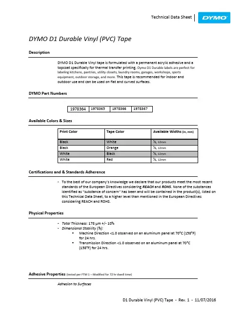
DYMO D1 Durable Vinyl (PVC) TapeDescriptionDYMO D1 Durable Vinyl tape is formulated with a permanent acrylic adhesive and atopcoat specifically for thermal transfer printing. Dymo D1 Durable labels are perfect forlabeling kitchens, pantries, utility closets, laundry rooms, garages, workshops, sportsequipment, outdoor storage, and more.This tape is recommended for indoor andoutdoor use and can be used on flat and curved surfaces.DYMO Part NumbersAvailable Colors & SizesCertifications and & Standards Adherence-To the best of our company’s knowledge we d eclare that our products meet the most recentstandards of the European Directives considering REACH and ROHS. None of the substancesidentif ied as “substance of concern“ has been and will be contained in the product(s), listed onthis Technical Data Sheet, to a higher level than mentioned in the European Directivesconsidering REACH and ROHS.Physical Properties-Total Thickness: 178 µm +/- 10%-Dimensional Stability (%):▪Machine Direction <1.0 observed on an aluminum panel at 70°C (158°F)for 24 hrs.▪Transmission Direction <1.0 observed on an aluminum panel at 70°C(158°F) for 24 hrs.Adhesive Properties (tested per FTM 1 – Modified for 72 hr dwell time)Adhesion to Surfaces-Tack (ASTM D 2979):800gm/cm²Temperature RatingsChemical ResistanceTest Method: Crockmeter, 900g weight/arm1. Printed with black ribbon:2. Printed with white ribbon:UV Light ResistanceHumidity Resistance-Printed labels adhered to aluminum surface for 30 days at 45°C (113°F), 85% Relative Humiditywith no visible effect on text or background; Slight shrinkage of materialShelf life of label cassette-Two years stored at 21°C (69.8°F) and 50% Relative HumidityNotice-This product is not developed to be used on humans, animals and/or in direct foodcontact. It is not recommended to be used in dish-washers.All of the descriptive information, performance data, and recommendations for the use of DYMO products shall be used only as a guide and do not reflect the specification or specification range for any particular property of the product. Furnishing such information is an attempt to assist you and in no event will constitute a warranty of any kind by DYMO or DYMO distributors. All purchasers of DYMO products shall be responsible for independently determining the suitability of the material for the purposefor which it is purchased.。

DRENAJEVENTAJASInnumerables son las ventajas para quien utiliza tubos y conexiones para drenaje de la marca TIGRE; estas son las más significativas:Mejor desempeño hidráulico. Por sus paredes internas lisas y por su mayor área de perforación por metro, los drena-jes corrugados y perforados TIGRE presentan mayor desem-peño hidráulico.Ligereza. Peso reducido en comparación a los materiales tradicionales.Economía. Debido a su flexibilidad, reducido peso y pérdi-das por quiebra prácticamente nulas, se torna un producto económico y de fácil transporte.Mayor vida útil. Posee aberturas adecuadamente dimen-sionadas, los drenajes de PVC TIGRE impiden la penetración y depósito del material filtrante, asegurando una mayor vida útil para el sistema.Facilidad en la instalación. Los tipos de unión, tanto soldable, elástica o simples encajes, le dan gran velocidad a la instalación, por la facilidad del montaje.Gran flexibilidad. Las propiedades de los materiales plásti-cos, aseguran la continuidad de la línea drenaje en los casos de deformaciones del suelo.Elevada resistencia a la compresión diametral. Las corrugaciones a lo largo del tubo aumentan su resisten-cia a la compresión diametral, dando mayor garantía a las cargas externas.Elevada resistencia química. No sufren la acción química del suelo, los tubos TIGRE para drenaje, garantizan una mayor vida útil a la red de drenaje.Largos. Fabricados en tiras de 6 metros para el tubo rígido, y rollos de 100 y 50 metros los tubos reducen mucho la mano de obra de la instalación.Conexiones. En el caso de los tubos flexibles se puede disponer de todas las conexiones del sistema Ramat domici-liario, siendo su unión perfecta.RECOMENDACIONES PARA INSTALACIÓNTIGRE ofrece a los ingenieros y técnicos esta nueva opción para drenaje subterráneo, presentando una línea de productos, introduciendo nuevos conceptos en las tradicionales técnicas hasta entonces utilizadas.No sólo la calidad de los drenajes de PVC TIGRE contribu-ye decisivamente para la preferencia de los proyectistas e instaladores, sino también las ventajas inherentes de estos productos, entre las cuales citamos: liviandad, elevada resistencia diametral, mayor área de perforación por metro y gran facilidad en la instalación, representando una mayor vida útil para el sistema de drenaje.Más adelante presentamos algunas orientaciones sobre la instalación de estos productos y recomendamos sean estudiados, con la finalidad de proporcionar el mayor desempeño y aprovechamiento de las ventajas que los mismos pueden ofrecer.02Para unir los tubos entre sí, usar la unión sencilla de 100 mm. Para desagües, con adhesivo Tigre para PVC. No utilizar anillo de goma.INSTALACIÓNCARACTERISTICAS DEL ACOPLAMIENTOLas piezas del acoplamiento del sistema DRENOFLEX, básicamente cuplas y adaptadores, presentan un sistema exclusivo de garras (desenvolvimiento TIGRE) que permi-ten introducir fácilmente el tubo y poseen una resistencia elevada al desmontaje (buena traba). La instalación puede proseguir con facilidad y sin peligro de desacoplamiento de las juntas que ya fueron montadas. A continuación se evidencia la facilidad del mecanismo de instalación.TUBO DRENOFLEXCONEXIÓN(LINEA RAMAT)ø 101,6DN 10003CARACTERÍSTICAS DIMENSIONALESCARACTERÍSTICAS DIMENSIONALES DE LOS TUBOSCARACTERÍSTICAS DIMENSIONALES DE LAS BOBINAS La planilla de abajo, son indicaciones con dimensiones aproximadas, cuyo objetivo es facilitar el planeamiento de transporte y el stock del material (volúmenes y pesos), también sirve como orientación para el desenvolvimiento de dispositivos de meca-nización de instalaciones, o para facilitar controles de stock y recibimiento de obra.0405APLICACIONESUtilizado en los más diversos tipos de drenaje, como ser edificaciones, carreteras, vías férreas, muros de contención, empasta-dos, campos deportivos, agricultura, y otros. Destacamos a continuación las más importantes, presentando nuestras recomen-daciones para que se obtenga un mejor desempeño de los mismos.Entre las aplicaciones en la Construcción Civil, destacamos el drenaje de muros de apoyo y el rebaje del nivelAPLICACIONES EN LA CONSTRUCCIÓN CIVILDrenaje en muros de apoyo• La calidad de los tubos de drenaje aplicados dependerá de la capacidad del filtro, extensión y altura del muro.• Normalmente, se hace más de una camada de tubos de drenaje para el escurrimiento del agua.• La aplicación de los tubos internos favorece la rapidez en el escurrimiento.• El filtro utilizado junto a la parte interna del muro deberá ser dimensionado para evitar la salida de partículas finas del material contenido.Rebaje del nivel freáticoLa protección de los predios contra las aguas de infiltración es otra de las aplicaciones usuales de los tubos de drenaje. Como en todas las aplicaciones, la distancia entre los drena-jes es en función de su profundidad y la capacidad del tubo es en función de la calidad del agua a drenar.Así, en esta aplicación, recomendamos mantener el declive constante y procurar no ahogar el drenaje.06APLICACIONES EN CAMINOS PAVIMENTADOSEs posible la utilización de la línea de drenaje para este fin pero es importante atender fin las especificaciones del proyectista. Las consideraciones generales se pueden apreciar en el gráfico.Fig. 3Fig. 4Para esas aplicaciones las formas de las líneas drenantes más empleadas son las espina de pez y paralelas.APLICACIÓN EN JARDINES Y CAMPOS DEPORTIVOSEn este caso, recomendamos:• Las distancias entre los drenajes, varían en función del suelo, pero como dato práctico, se puede adoptar la siguiente distancia:10 metros – para terrenos con más de 70 % de arcilla 15 metros – para terrenos con media mezcla (40% de arcilla).20 metros – para terrenos con un máximo de 20 % de arcilla.• P rocurar mantener la pendiente en todas las líneas, eliminando los posibles depósitos, debidos a la velocidad constante.• La profundidad deberá estar entre 0,8 a 1 metro.APLICACIONES EN LA INFILTRACIÓN DE DESAGÜES SANITARIOSLos tubos de drenaje presentan una práctica solución en la disposición de los afluentes de Cámaras Sépticas, (Fosas) ,a través del sistema de infiltración en el terreno.En esta aplicación, recomendamos observar los siguientes puntos:• Mantener una distancia mínima de 30 metros, entre las líneas de infiltración y la fuente de abastecimiento del agua.• El declive entre la cámara séptica y la caja de distribución debe ser mantenido en 2%, en cuanto que para la infiltración• La granulometría del cascajo para el lecho de la línea de riego deberá estar comprendida entre 1 a 6 cm.• Las dimensiones y el tipo de relleno de zanja deberán seguir el esquema de la Fig.7.• Todas las salidas de la caja de distribución deberán estar en el mismo nivel.•Fig. 6Fig. 70708APLICACIONES EN EL DRENAJE AGRÍCOLALa opción del tipo de drenaje: de descarga (paralelo o espina de pez) o interceptor; el cálculo del espacio entre los drenajes y su dimensionamiento y requieren estudiosDe una manera general, la profundidad de los drenajes para regiones áridas está entre 1,5 a 2 metros, en cuanto que para regiones húmedas, de 1 a 1,5 metros.ASENTAMIENTODeberán ser tomadas medidas de precaución para el asentamiento, previendo un material de buen soporte lateral para cuando el tubo estuviera sujeto a grandes cargas de compresión, a fin de evitar una deformación diametral, no compatible con el uso.En cuanto al filtro que envuelve los tubos, se debe prever su correcto dimensionamiento, para que con el correr del tiempo, tengamos siempre un buen sistema drenante.Para eso determinadas condiciones como uniformidad y permeabilidad del filtro deberán ser observadas.En la página siguiente presentamos una tabla con datos de los tubos TIGRE de PVC para drenaje, que auxiliarán los cálculos del sistema drenante.FIG. 909COLOCACIÓN PUNTERA HEMBRAEN TUBO RÍGIDOA – Material necesario: trapo, pincel, lija Nº100, solución limpiadora TIGRE y adhesivo TIGRE.B – Lijar internamente la bolsa deltubo, hasta sacar todo el brillo.C – Lijar externamente la punta del tubo, hasta sacar el brillo.D – Limpiar con el trapo humedecido con solución limpiadora TIGRE, lapuntera hembra y el tubo ya lijados.E – Medir la profundidad de la bolsa.F – Marcar en la punta del tubo laprofundidad de la bolsa.G – Utilizar el pincel para aplicar, sin exceso, el adhesivo TIGRE en la bolsa del tubo.H – Aplicar igualmente el adhesivo TIGRE, en la puntera.Si el tubo fuera Drenoflex se puede considerar la utilización de una cupla deslizante de 110 de la línea Ramat. En caso de lecho nitrificante consultar al departamento técnico.I – Introducir la punta del tubo en elfondo de la bolsa, observando laposición de la marca hechaanteriormente.J – La junta soldada está lista.REPARACIÓN DE PEQUEÑAS ROTURASA –Cuando hay pequeñas roturas enla red, utilizar una sierra para cortar eltrecho damnificado.B – Cortar una cupla doble en elsentido longitudinal.C – Lijar (lija nº100) externamente lasextremidades del tubo cortado einternamente la cupla.D – Con el trapo humedecido con lasolución limpiadora TIGRE, limpiar laspartes lijadas.E – Utilizando un pincel aplicaradhesivo TIGRE sobre las superficiesdel tubo anteriormente lijadas.F – Aplicar igualmente el adhesivoTIGRE, en la parte interna de la cupla.G – Ejerciendo presión manual, abrirla cupla para encajarla sobre el tubo.H – La ejecución de la reparaciónestá lista.1011ROTURAS MAYORES CATÁLOGO DE PIEZASY DIMENSIONESRoturas mayores Cuando existe una rotura mayor en el tubo, se corta, con ayuda de un sierra, el trecho damnificado, y de otro tubo se corta una parte con el mismo largo al de la parte retirada menos dos veces la anchura del anillo de la cupla.Se coloca este tubo en el espacio de la línea. Se suelda con adhesivo TIGRE una cupla en una de las extremidades de la tubería, con una de las extremidades del tubo intercalado.Para completar el reparo de la otra extremidad, se corta una cupla en el mismo sentido longitudinal y por medio del adhe-sivo se fija la misma sobre la enmienda existente, comple-tándose de esta manera el arreglo.Para la ejecución del pegado de las dos cuplas, sólo hay que seguir las especificaciones apuntadas para el reparo de la red anterior.Enmiendas de tubos cortados Cuando se hace necesario el acoplamiento o el aprovecha-miento de pedazos de tubos cortados, la unión de los mismos deberá ser hecha con la ayuda de la cupla, que es insertada sobre la corrugación helicoidal de los tubos. DrenoflexCotas (mm)L (mm)DE (mm)Ø 65Ø 110Código 008000815000500065.2110Di(mm)58101.40085Cotas (mm)L (mm)DE(mm)Ø 100Código 6000101.6Drenaje RígidoCotas (mm)A (mm)B (mm)Ø100X101.6Código 324114265C (mm)55D (mm)101.6DE (mm)101.6Reducción 110x100Cotas (mm)A (mm)D(mm)Ø 100Código 1339132110Puntera Hembra。
退刀应灵活
2、锯片不应有掉齿现象2、找一节型材进行切割看是否有大的破口
汽缸下
、
1、标准操作工
依据制造异常处理方法处理
2、自然光线下目测其外观
未设标准操作工艺卡者反映
1、用游标卡尺量取型材配合尺寸,几何尺寸
3、真空度不够
4、物料温度偏低
5、模头与定型模距离太远
6、真空度不够
7、一级定型套内有物料3、增加密封,提高真空度 ,调试真空泵
4、调整模头与挤出机温度(生温度)
5、减小模头与定型模之间的距离
6、条件允许时,可在收缩痕部位增加气孔
7、清理定型套
堵塞
3、牵引速度太慢(挤出和牵引不匹配)
4、型材局部出料不均匀
5、局部温度失控
6、机身模头温度不稳定,忽高忽低
7、定型模进料口导入斜度过小过短
8、定型模堵模处尺寸小2、检查,调整牵引机
3、提高牵引速度
4、调整间隙至均匀
5、检查加热板是否失控
6、检查温控系统,调整温度稳定
7、增大定型模进料口模斜度和长度
8、加大其尺寸
2、第一节定型模真空度太高或太稳定
3、定型模不在一条直线上,阻力过大
4、局部阻力过大
5、冷却不充分2、适当降低真空,检查真空泵
3、检查定型模是否在一条直线上
4、在许可时减少供料,修正定型模,增大间隙
5、降低水温,局部拐弯第一节加强冷却
2、牵引速度过快或过慢
3、型材两侧大面供料不够
4、冷却不充分
5、牵引机压力过大2、调节牵引速度使型材到达标准重量
3、加强两侧供料
4、降低冷却水温或加大冷却水量
5、适当降低牵引机压力。
Windows 2000 English with Service Pack 4 is used as operating system for controlling and operating PC.采用Windows 2000 English with Service Pack 4 操作系统。
Visual system with VAC_NT, Version 3.0 带VAC_NT的可视化系统, 3.0版本Graphic visualization of all data, set points, process states and user inputs 所有数据,设定点,过程状态和用户输入的图像可视化Menu-controlled process operating with keyboard and touch pad.带键盘和触摸板的菜单控制过程操作Manual operation for selected functions. 已选功能的人工操作Automatic operation for processes using parameters 使用参数过程的自动操作Database-oriented control and management of procedures 数据库导向控制和管理程序Event-controlled message logging 事件控制信息的录入Protocol recording during the process run 工艺运行过程的协议记录Diagnosis function (I/O list) 诊断功能(I/O 清单)1.3 Installation instruction for the main components 主要元件的安装指示For the installation of the SIMATIC peripheral components see the section in the System manual “Local peripheral equipment ET200M” (Order No.: 6ES7 153-1AA01-8AA0). SIMATIC外围元件的安装参见系统手册“Local peripheral equipment ET200M” (Order No.: 6ES7 153-1AA01-8AA0).For SINEC-L2 connection comply with the Technical Description and the Installation Guidelines in the Manual “CP5613”. SINEC-L2的连接遵守技术描述和和安装向导,在手册“CP5613”。
PVC Schedule 80 FittingsPRODUCTContact Spears® for any Information not found.TeesPart Number Size StdPkMstrCtnProdCodeMSRPTeeSocket x Socket x Socket801-0021/45030008019.46 801-0033/82515008019.46 801-0051/22520008019.46 801-0073/41512008020.40 801-010*********.53 801-0121-1/410008070.16 801-0151-1/210008070.16 801-020*********.73 801-0252-1/210008095.36 801-030350080119.20 801-040450080138.11 801-050550080336.89 801-050F514083787.41 801-060620080471.56 801-0808200801093.69 801-080F8100831031.61 801-10010100813613.30 801-100F10100831833.30 801-12012100815102.99 801-120F12100832583.21 801-14014100826424.61 801-140F14100835419.46 801-160F16100837046.96 801-180F181********.51 801-200F201008310822.56 801-240F241008314383.50 Tee - ReducingSocket x Socket x Socket801-1013/4X1/21512008014.94 801-1301X1/215008021.56 801-1311X3/415008021.56 801-1571-1/4X1X3/415008035.61 801-1581-1/4X1X115008035.61 801-1591-1/4X1X1-1/415008035.61 801-16611-1/4X1/210008059.52 801-1671-1/4X3/410008046.83 801-1681-1/4X115008046.83 801-2021-1/2X1-1/4X110008046.83 801-2091-1/2X1/210008046.83 801-2101-1/2X3/415008046.83 801-2111-1/2X110008046.83 801-2121-1/2X1-1/410008046.83 801-2472X1/210008059.32 801-2482X3/410008059.32 801-2492X110008059.32Part Number SizePk Ctn CodeMSRP Tee - Reducing (continued)Socket x Socket x Socket801-2502X1-1/410008090.46 801-2512X1-1/210008059.32 801-25412X2X450080414.42 801-2872-1/2X1/210008090.69 801-2882-1/2X3/410008090.69 801-2892-1/2X110008077.40 801-2902-1/2X1-1/410008077.40 801-2912-1/2X1-1/210008077.40 801-2922-1/2X210008077.40 801-33313X1/250080108.77 801-3343X3/460080122.77 801-3353X150080108.77 801-33613X1-1/450080108.77 801-3373X1-1/250080108.77 801-3383X250080108.77 801-3393X2-1/260080108.77 801-41514X1/250080215.12 801-41614X3/450080215.12 801-4174X150080215.12 801-41814X1-1/450080215.12 801-4194X1-1/250080175.78 801-4204X250080175.78 801-42114X2-1/250080316.42 801-4224X350080175.78 801-42614X640080861.43 801-48215X1-1/440080696.93 801-482F5X1-1/415083465.98 801-48415X1-1/240080759.78 801-484F5X1-1/215083474.78 801-48615X240080661.09 801-486F5X215083474.78 801-48715X2-1/240080769.06 801-487F5X2-1/214083541.38 801-48815X340080661.09 801-488F5X314083559.09 801-49015X440080524.37 801-490F5X414083596.86 801-52316X1/240080457.14 801-52416X3/460080457.14 801-5256X160080351.22 801-525F16X140083406.29 801-52616X1-1/440080457.14 801-52716X1-1/240080457.14 801-527F6X1-1/214083474.78 801-5286X260080351.22 801-52916X2-1/240080456.74 801-5306X350080351.22 801-530F6X313083519.23 801-5326X450080471.56 801-533F6X513083992.62 801-537F6X10100833863.58 801-539F6X12100834289.86 801-57318X1/2200801342.00 801-57518X1200801342.80TeesPart Number Size StdPkMstrCtnProdCodeMSRPTee - Reducing (continued)Socket x Socket x Socket801-57818X2200801276.83 801-578F8X212083875.84 801-57918X2-1/2200801404.88 801-579F8X2-1/212083883.96 801-58018X3200801276.83 801-580F8X312083893.89 801-5828X4200801276.83 801-582F8X412083939.92 801-583F8X5100831270.67 801-5858X6200801093.69 801-59118X12100817802.17 801-621F10X2120831315.67 801-622F10X2-1/2100831374.14 801-623110X3100813366.52 801-623F10X3100831411.03 801-624110X4100813366.52 801-624F10X4100831461.81 801-625F10X5100831572.01 801-62610X6100813179.71 801-626F10X6100831653.21 801-628110X8100813742.09 801-628F10X8100831854.64 801-632F10X12100834568.57 801-661F12X2100831701.29 801-662F12X2-1/2100831774.71 801-663F12X3100831832.63 801-664112X4100816103.62 801-664F12X4100831944.08 801-665F12X5100832037.26 801-666112X6100815758.62 801-666F12X6100832146.64 801-66812X8100814730.49 801-668F12X8100832303.08 801-670112X10100816334.78 801-670F12X10100832559.19 801-678F12X181008311407.49 801-691F14X2100832131.71 801-692F14X2-1/2100832239.48 801-693F14X3100832617.16 801-694F14X4100832884.08 801-696F14X6100833113.37 801-698114X8100827328.99 801-698F14X8100833273.89 801-700114X10100825204.68 801-700F14X10100833497.60 801-70214X12100826058.66 801-702F14X12100833693.23 801-706F14X16100838885.56 801-751F16X2100832733.58 801-752F16X2-1/2100832907.52 801-753F16X3100832949.20Part Number SizePk Ctn CodeMSRP Tee - Reducing (continued)Socket x Socket x Socket801-620F10X1-1/2100833245.37 801-754F16X4100833226.49 801-756F16X6100833432.48 801-758F16X8100833812.51 801-760F16X10100834132.80 801-762F16X12100834554.43 801-764F16X14100835251.63 801-781F18X2100833142.42 801-783F18X3100833826.03 801-784F18X4100835875.80 801-786F18X6100836364.06 801-788F18X8100836636.57 801-790F18X10100837109.79 801-792F18X12100837513.62 801-794F18X14100837985.10 801-796F18X16100838087.12 801-814F20X4100837206.31 801-816F20X6100837609.11 801-818F20X8100837842.99 801-820F20X10100838167.11 801-822F20X12100838757.22 801-824F20X14100839390.93 801-826F20X161008310065.36 801-828F20X181008310579.51 801-904F24X4100838972.80 801-906F24X6100839316.46 801-908F24X8100839558.70 801-910F24X101008310146.97 801-912F24X121008310521.37 801-914F24X141008310955.53 801-916F24X161008311460.94 801-918F24X181008313862.66 801-920F24X201008314126.00 1 Sized with BushingTeeSocket x Socket x Fipt802-0021/42515008045.02 802-0051/22016008030.81 802-0073/42016008039.84 802-010*********.63 802-0121-1/415008049.82 802-0151-1/210008058.58 802-020*********.26 802-0252-1/250080143.58 802-030350080154.18 802-040450080289.67 802-060F620083596.53 802-080F8120841277.44TeesPart Number Size StdPkMstrCtnProdCodeMSRPTee - ReducingSocket x Socket x Fipt802-1013/4X1/21512008028.29 802-1301X1/250008029.40 802-1311X3/415008037.78 802-1661-1/4X1/225008048.07 802-16711-1/4X3/415008048.07 802-1681-1/4X110008095.42 802-20911-1/2X1/225008059.52 802-21011-1/2X3/420008059.52 802-2111-1/2X110008059.52 802-2121-1/2X1-1/410008059.52 802-2472X1/210008067.99 802-2482X3/410008067.99 802-2492X110008090.46 802-25012X1-1/410008090.46 802-25112X1-1/2100080126.14 802-2872-1/2X1/2100080156.54 802-28812-1/2X3/4100080156.54 802-28912-1/2X1100080156.54 802-29012-1/2X1-1/4100080156.54 802-29112-1/2X1-1/2100080156.54 802-29212-1/2X2100080174.78 802-33313X1/250080122.77 802-33413X3/450080122.77 802-33513X150080147.66 802-33613X1-1/450080147.66 802-33713X1-1/250080147.66 802-33813X250080188.54 802-33913X2-1/250080265.17 802-41514X1/250080216.03 802-41614X3/450080216.03 802-41714X150080216.03 802-41814X1-1/450080216.03 802-41914X1-1/250080216.03 802-42014X250080322.90 802-42114X2-1/250080322.90 802-42214X350080361.48 802-52516X140080502.66 802-52616X1-1/440080502.66 802-52716X1-1/240080502.66 802-52816X240080502.66 802-528F26X213083915.40 802-52916X2-1/240080502.66 802-53016X340080701.71 802-53216X420080735.21 802-532F26X4140831134.37 802-57818X2200801370.02 802-578F8X2120831225.94 802-58018X3200801370.02Part Number SizePk Ctn CodeMSRP Tee - Reducing (continued)Socket x Socket x Fipt802-580F8X3120831225.94 802-58218X4200801370.02 802-582F28X4120831358.81 802-621110X2100813498.68 802-621F10X2100831488.66 802-623110X3100803498.68 802-623F10X3100831609.18 802-624110X4100813498.68 802-624F210X4100831787.72 802-661112X2100815543.58 802-661F12X2100831890.92 802-663112X3100815543.58 802-663F12X3100832051.81 802-664112X4100815543.58 802-664F12X4100832264.691 Sized with Bushing2 Fiberglass reinforcedTee - Special ReinforcedSocket x Socket x SR Fipt - Stainless SteelCollar802-005SR1/250008616.83 802-007SR3/41512008623.82 802-010SR115008627.96 802-012SR1-1/425008633.30 802-015SR1-1/210008635.17 802-020SR210008668.81 802-030SR350086148.71 802-040SR450086278.86 Tee - Special Reinforced ReducingSocket x Socket x SR Fipt - Stainless SteelCollar802-072SR1/2X1/42515008616.83 802-098SR3/4X1/42510008621.88 802-101SR3/4X1/250008621.88 802-128SR11X1/4108008651.80 802-130SR1X1/250008626.99 802-131SR1X3/415008651.80 802-164SR11-1/4X1/454008655.22 802-166SR1-1/4X1/225008636.61 802-168SR1-1/4X110008637.34 802-207SR11-1/2X1/410008664.44 802-211SR1-1/2X110008640.44 802-212SR1-1/2X1-1/410008640.44 802-245SR12X1/410008674.42 802-247SR2X1/210008674.42 802-248SR2X3/410008674.42 802-287SR2-1/2X1/210008654.86 802-331SR13X1/450086142.10 802-333SR13X1/250086146.23TeesPart Number Size StdPkMstrCtnProdCodeMSRPTee - Special Reinforced Reducing (continued)Socket x Socket x SR Fipt - Stainless Steel Collar802-413SR14X1/450086195.69 802-415SR14X1/250086212.681 Sized with BushingTee - Brass TransitionSocket x Socket x Fipt With Brass Thread Insert802-005BR1/22012008668.79 802-007BR3/42080086137.84 Not intended to convey or dispense water for human consumption through drinking or cookingTee - Brass Transition ReducingSocket x Socket x Fipt With Brass Thread Insert802-072BR1/2X1/42012008674.14 802-101BR3/4X1/250008685.84 Not intended to convey or dispense water for human consumption through drinking or cookingTee - ReducingSocket x Fipt x Socket803-0953/4X1/2X3/450008026.51 Tee - Special Reinforced ReducingSocket x SR Fipt - Stainless Steel Collar xSocket(See also Gauge & Instrument Fittings for additional configurations)803-095SR3/4X1/2X3/415008627.56TeeFipt x Fipt x Fipt805-0021/42515008022.52 805-0033/82515008022.52 805-0051/22024008022.52 805-0073/41512008025.04 805-010*********.30 805-0121-1/410008058.63 805-0151-1/210008071.08 805-020*********.41 805-0252-1/250080278.26 805-030350080290.60 805-040450080472.24Part Number SizePk Ctn CodeMSRPTee (continued)Fipt x Fipt x Fipt805-060F6120801019.09 805-080F8100802007.19 Tee - Special ReinforcedSR Fipt x SR Fipt x SR Fipt - Stainless SteelCollar805-002SR1/42515008619.62 805-003SR3/82515008619.62 805-005SR1/22515008620.23 805-007SR3/42510008622.23 805-010SR115008652.82 805-015SR1-1/210008661.86 805-020SR210008665.02 Tee - StreetSpigot x Socket x Socket844-0051/22520008024.34 844-0073/41512008025.53 844-010*********.92 844-0121-1/410008087.73 844-0151-1/210008087.73 844-0202100080109.6290° Ells90° EllSocket x Socket806-0021/450300080 6.88 806-0033/825150080 6.88 806-0051/220240080 6.88 806-0073/4201600808.82 806-010*********.22 806-0121-1/410008019.04 806-0151-1/225008020.38 806-020*********.62 806-0252-1/25008057.64 806-03036008064.80 806-04045008098.54 806-045F4-1/212083453.07 806-050540080252.63 806-050F514083505.88 806-060640080280.41 806-080820080772.90 806-080F812083776.54 806-10010100813458.96 806-100F10100831380.41 806-12012100814509.01 806-120F12100832256.3390° EllsPart Number Size StdPkMstrCtnProdCodeMSRP90° Ell (continued)Socket x Socket806-14014100825055.59 806-140F14100832878.21 806-160F16100833579.58 806-180F181********.70 806-200F20100836109.23 806-240F24100839381.49 806-33813X250080158.84 806-42214X350080237.27 1 Sized with Bushing90° Ell SweepSocket x Socket806-005S1/22515008017.22 806-007S3/42510008022.28 806-010S120008035.91 806-012S1-1/425008047.53 806-015S1-1/220008051.04 806-020S225008061.86 90° Ell - Long SweepSocket x Socket806-005LSF1/22520008359.70 806-007LSF3/425008367.01 806-010LSF125008374.92 806-012LSF1-1/4250083126.68 806-015LSF1-1/2125083128.30 806-020LSF2110083138.69 806-025LSF2-1/217083238.16 806-030LSF315083259.81 806-040LSF414083291.34 806-060LSF612083446.27 806-080LSF810083935.26 806-100LSF10100831591.33 Not Listed for Electrical Conduit Use90° EllSocket x Fipt807-0021/42545008027.16 807-0033/82515008027.16 807-0051/22024008027.16 807-0073/42024008031.96 807-010*********.58 807-0121-1/4104008039.84 807-0151-1/210008047.56 807-020*********.56Part Number SizePk Ctn CodeMSRP 90° Ell (continued)Socket x Fipt807-030350080147.08 807-040450080277.38 807-0601630080643.59 1 Thread outlet sized with Female Adapter90° Ell - ReducingSocket x Fipt807-1013/4X1/2106008016.47 807-13011X1/2108008026.28 807-13111X3/4108008026.28 1 Sized with Bushing90° Ell - Special ReinforcedSocket x SR Fipt - Stainless Steel Collar807-005SR1/22024008616.14 807-007SR3/475008619.18 807-010SR150008619.39 807-012SR1-1/425008626.09 807-015SR1-1/210008632.21 807-020SR210008636.93 807-030SR35008693.82 807-040SR450086165.7690° Ell - Special Reinforced ReducingSocket x SR Fipt - Stainless Steel Collar807-101SR3/4X1/250008619.12 807-130SR1X1/250008621.4890° Ell - Brass TransitionSocket x Fipt With Brass Thread Insert807-005BR1/22024008660.44 807-007BR3/420160086106.99 Not intended to convey or dispense water for human consumption through drinking or cooking90° Ell - Brass Transition ReducingSocket x Fipt With Brass Thread Insert807-101BR3/4X1/22012008675.40 Not intended to convey or dispense water for human consumption through drinking or cooking90° EllsPart Number Size StdPkMstrCtnProdCodeMSRP90° EllFipt x Fipt808-0021/42545008017.12 808-0033/82515008017.12 808-0051/22012008015.98 808-0073/42024008019.93 808-01011512008025.04 808-0121-1/4104008026.99 808-0151-1/210008038.28 808-020*********.12 808-0252-1/250080167.94 808-030350080270.84 808-040450080476.53 90° Ell - Special ReinforcedSR Fipt x SR Fipt - Stainless Steel Collar808-003SR3/8251500869.43 808-005SR1/2201200869.43 808-007SR3/42012008611.86 808-010SR150008613.82 808-012SR1-1/425008614.73 808-015SR1-1/210008622.99 808-020SR210008625.88 90° Street EllSpigot x Socket809-0051/2502000808.67 809-0073/450008011.04 809-010*********.80 809-0121-1/425008023.82 809-0151-1/210008025.53 809-020*********.82 809-02512-1/25008073.03 809-03035008086.46 809-040440080131.38 809-0601610080373.89 809-08018200801030.53 809-100110100814610.68 809-100F10100831840.61 809-120112*********.17 809-120F12100833008.46 809-140114*********.52 809-140F14100833676.73 809-160F16100833977.36 809-180F181********.48 809-200F20100839568.28Part Number SizePk Ctn CodeMSRP 90° Street Ell (continued)Spigot x Socket809-240F241008314867.64 1 = Assembled with Molded Components90° Street EllMipt x Fipt812-0021/45030008036.86 812-00511/22515008030.59 812-0073/42515008034.74 812-0101150008047.24 812-01211-1/410008054.28 812-01511-1/210008088.92 1 Sized with AdapterNon 90° Ells11-1/4° EllSocket x Socket811-005F1/215208355.89 811-007F3/412008356.28 811-010F115008361.56 811-012F1-1/412608366.69 811-0151-1/225008055.74 811-020*********.33 811-025F2-1/212508381.71 811-0303100080175.19 811-040440080314.84 811-045F4-1/2118083178.01 811-050F514083213.50 811-060F6110083218.49 811-080F814083357.64 811-100F1012083633.84 811-120F1212083926.40 811-140F14100831418.23 811-160F16100831895.80 811-180F181********.34 811-200F20100834222.22 811-240F24100835037.4930° EllSocket x Socket815-005F1/212508355.89 815-007F3/412508356.28 815-010F113008361.56 815-012F1-1/411508366.69 815-015F1-1/212508367.61 815-020F212508373.73 815-025F2-1/211808381.71Non 90° EllsPart Number Size StdPkMstrCtnProdCodeMSRP30° Ell (continued)Socket x Socket815-030F312008389.12 815-040F416083116.84 815-045F4-1/2118083178.01 815-050F514083213.50 815-060650080396.38 815-080F813083357.64 815-100F1012083633.84 815-120F1212083926.40 815-140F14100831418.23 815-160F16100831895.80 815-180F181********.33 815-200F20100834222.22 815-240F24100835037.49 22-1/2° EllSocket x Socket816-0051/22024008015.34 816-0073/42024008023.39 816-01012016008035.06 816-010F112508333.82 816-015F1-1/212508358.97 816-0121-1/420008044.63 816-0151-1/220008052.77 816-020*********.33 816-0252-1/250080140.43 816-025F2-1/211808381.71 816-030350080175.19 816-040440080314.84 816-045F4-1/2118083178.01 816-050F518083213.50 816-060640080396.38 816-060F618083218.49 816-080840080859.60 816-080F814083357.64 816-100F1012083633.84 816-120F1212083926.40 816-140F14100831418.23 816-160F16100831895.80 816-180F181********.34 816-200F20100834222.22 816-240F24100835037.49 45° EllSocket x Socket817-0021/42545008024.80 817-0033/85030008024.80 817-0051/22024008012.98Part Number SizePk Ctn CodeMSRP 45° Ell (continued)Socket x Socket817-0073/42024008019.87 817-01011512008029.77 817-0121-1/4108008037.92 817-0151-1/210008044.84 817-020*********.14 817-0252-1/250080122.08 817-030350080148.62 817-040450080267.57 817-045F4-1/212083185.37 817-050540080320.13 817-050F514083252.96 817-060640080336.97 817-080820080730.60 817-10010100812300.20 817-100F1012083970.76 817-12012100812967.10 817-120F12100831365.72 817-14014100823483.84 817-140F14100832226.08 817-160F16100832725.26 817-180F181********.07 817-200F20100834556.18 817-240F24100835643.5615° EllSocket x Socket818-005F1/212508355.89 818-007F3/412308356.28 818-010F112008361.56 818-015F1-1/212508367.61 818-020F212508373.73 818-025F2-1/2118083240.69 818-030F313508389.12 818-040F4120083116.84 818-045F4-1/2118083178.01 818-050F514083213.50 818-060F618083218.49 818-080F814083357.64 818-100F1012083633.84 818-120F1212083926.40 818-140F14100831418.23 818-160F16100831895.80 818-180F181********.34 818-200F20100834222.22 818-240F24100835037.4945° EllFipt x Fipt819-0021/42545008028.16Non 90° EllsPart Number Size StdPkMstrCtnProdCodeMSRP45° Ell (continued)Fipt x Fipt819-0033/82515008028.16 819-0051/22515008025.68 819-0073/4106008027.58 819-0101106008034.61 819-0121-1/4108008052.78 819-0151-1/210008066.36 819-020*********.39 819-0252-1/250080194.67 819-030350080313.13 819-040450080449.30 45° Ell - Special ReinforcedSR Fipt x SR Fipt - Stainless Steel Collar819-005SR1/22515008614.82 819-007SR3/42530008616.22 819-010SR1106008626.82 60° EllSocket x Socket824-005F1/217083155.12 824-007F3/4125083183.14 824-010F1125083199.26 824-012F1-1/4116083203.17 824-015F1-1/2116083217.02 824-020F2116083275.31 824-025F2-1/2110083324.11 824-030F314083324.73 824-040F414083417.23 824-060F612083745.18 824-080F812083903.16 824-100F10120831543.11 824-120F12100832015.52 824-140F14100832509.76 824-160F16100832835.76 824-180F181********.89 824-200F20100835540.52 824-240F24100839239.07 45° Street EllSpigot x Socket827-0051/25040008012.98 827-0073/450008019.87 827-010*********.77 827-0121-1/425008037.92 827-0151-1/225008044.84Part Number SizePk Ctn CodeMSRP 45° Street Ell (continued)Spigot x Socket827-020*********.14 827-02512-1/212008076.67 827-0303100080148.62 827-040450080267.57 827-050F512083323.72 827-060640080396.38 827-080820080859.60 827-100110100812706.21 827-120112*********.72 827-140F14100832054.62 827-160F16100833295.88 827-180F181********.46 827-200F20100834847.16 827-240F24100837707.37 1 = Assembled with Molded Components22-1/2° Street EllSpigot x Socket842-0051/25040008015.91 842-0073/450008024.49 842-010*********.46 842-0121-1/420008047.90 842-0151-1/225008054.28 842-020*********.33 842-0252-1/250080178.43 842-030350080195.88 842-040440080344.46 842-040F415084219.46 842-060660080489.58 842-060F616083275.31 842-0808120801058.48 842-080F814083363.34 842-100F1010083742.57 842-120F1212084967.57CrossesCrossSocket x Socket x Socket x Socket820-0021/42515008096.03 820-0051/250008096.03 820-0073/4500080101.03 820-0101500080118.31 820-0121-1/4250080141.96 820-0151-1/2250080153.02 820-0202100080189.49 820-0252-1/2100080258.36 820-030350080322.23 820-040430080560.66CrossesPart Number Size StdPkMstrCtnProdCodeMSRPCross (continued)Socket x Socket x Socket x Socket820-060F6100831347.24 820-080F8100831969.94 820-100F10100833177.33 820-120F12100834474.42 820-140F14100837191.16 820-160F16100838149.83 820-180F181********.39 820-200F201008312447.26 820-240F241008318704.54 Cross - ReducingSocket x Socket x Socket x Socket820-10113/4X1/2500080111.29 820-13011X1/2250080144.19 820-1311X3/4200080144.19 820-16611-1/4X1/2250080138.49 820-1671-1/4X3/4250080127.79 820-16811-1/4X1250080182.10 820-20911-1/2X1/2200080206.53 820-2101-1/2X3/4150080206.53 820-21111-1/2X1250080206.53 820-21211-1/2X1-1/4250080206.53 820-24712X1/2100080264.93 820-24812X3/4100080264.93 820-24912X1100080264.93 820-25012X1-1/4100080264.93 820-25112X1-1/2100080264.93 820-2892-1/2X1150080264.93 820-29012-1/2X1-1/4100080388.11 820-29112-1/2X1-1/2100080388.11 820-29212-1/2X240080388.11 820-33513X140080526.30 820-33613X1-1/440080526.30 820-33713X1-1/240080526.30 820-33813X240080526.30 820-33913X2-1/240080526.30 820-42014X230080845.58 820-420F4X214083825.79 820-42214X330080845.58 820-527F6X1-1/212083979.86 820-528F6X2140831045.56 820-530F6X3120831099.22 820-532F6X4120831310.18 820-533F6X5120831553.34 820-578F8X2120831349.19 820-580F8X3100831420.29 820-582F8X4100831466.86 820-585F8X6100831585.13 820-621F10X2100831796.03Part Number SizePk Ctn CodeMSRP Cross - Reducing (continued)Socket x Socket x Socket x Socket820-622F10X2-1/2100831846.34 820-623F10X3100831947.42 820-624F10X4100832021.44 820-626F10X6100832115.43 820-628F10X8100832720.53 820-661F12X2100832009.42 820-663F12X3100832164.90 820-664F12X4100832304.07 820-666F12X6100832675.62 820-668F12X8100833196.19 820-670F12X10100832173.78 820-691F14X2100832883.31 820-693F14X3100833103.03 820-694F14X4100833407.03 820-696F14X6100833763.12 820-698F14X8100834280.78 820-700F14X10100834946.01 820-702F14X12100835594.37 820-751F16X2100833607.10 820-753F16X3100833884.57 820-754F16X4100834309.28 820-756F16X6100834660.61 820-758F16X8100835212.84 820-760F16X10100835680.43 820-762F16X12100836380.10 820-764F16X14100837990.12 820-784F18X4100836082.96 820-786F18X6100836348.99 820-788F18X8100836813.63 820-790F18X10100837277.97 820-792F18X12100837621.12 820-794F18X14100838074.88 820-796F18X16100838413.97 820-814F20X4100837627.49 820-816F20X6100838785.79 820-818F20X8100838884.48 820-820F20X10100839498.20 820-822F20X121008310184.58 820-824F20X141008311372.04 820-826F20X161008311593.79 820-828F20X181008312220.06 820-904F24X4100839106.12 820-906F24X6100839679.12 820-908F24X81008310057.10 820-910F24X101008310200.77 820-912F24X121008310666.74 820-914F24X141008312691.98 820-916F24X161008313553.70 820-918F24X181008315551.56 820-920F24X201008318595.20 1 Sized with BushingPage 13See MSRP-1 Sheet or Check Spears®****************************.comforPricingCouplingsCodeRepair Coupling- FabricatedGasket x GasketCoupling - No StopSocket x Socket - No Pipe Stop0811360.07CouplingSocket x Socket(continued)0832593.64Coupling - ReducerSocket x SocketMade in the U.S.A.Suitable for Oil-Free air handling to 25 psi, not for distribution of compressed air or gasSee MSRP-1 Sheet or Check Spears®****************************.comforPricing Page 14CouplingsPart Number Size StdPkMstrCtnProdCodeMSRPCoupling - Reducer (continued)Socket x Socket829-491F5X4-1/2110083179.47 829-52816X260080619.33 829-52916X2-1/240080742.72 829-53016X3120080625.69 829-530F6X3110083233.50 829-5326X440080504.51 829-534F6X4-1/215083204.10 829-533F6X515083214.03 829-579F8X2-1/216083807.89 829-580F8X316083592.16 829-5828X4200801528.04 829-582F8X416083552.59 829-583F8X514083607.42 829-5858X6200801528.04 829-621F10X212083953.18 829-623F10X312083892.37 829-624F10X412083842.19 829-625F10X514083765.78 829-62610X6100811788.90 829-626F10X614083690.16 829-62810X8100811788.90 829-628F10X814083359.18 829-663F12X3120831375.86 829-664F12X4120831175.32 829-665F12X5120831090.40 829-666F12X6100831016.69 829-66812X8100812035.61 829-668F12X810083787.21 829-670F12X1010083531.79 829-691F14X2100831253.41 829-694F14X4100831354.11 829-696F14X6100831446.44 829-698F14X8100831323.59 829-700F14X10100831294.54 829-702F14X1210083776.46 829-754F16X4100832542.51 829-756F16X6100832299.49 829-758F16X8100832019.58 829-760F16X10100831793.88 829-762F16X12100831512.08 829-764F16X14100831147.82 829-783F18X3100835516.88 829-784F18X4100835364.63 829-786F18X6100835014.70 829-788F18X8100834748.09 829-790F18X10100834295.18 829-792F18X12100833535.44 829-794F18X14100832393.36 829-796F18X16100832043.28 829-814F20X4100835311.04 829-816F20X6100834889.99Part Number SizePk Ctn CodeMSRP Coupling - Reducer (continued)Socket x Socket829-818F20X8100834673.89 829-820F20X10100834509.97 829-822F20X12100833901.50 829-824F20X14100833891.22 829-826F20X16100833574.47 829-828F20X181********.87 829-904F24X4100838495.49 829-906F24X6100838366.14 829-908F24X8100838184.84 829-910F24X10100837987.41 829-912F24X12100837266.14 829-914F24X14100836702.06 829-916F24X16100836107.99 829-918F24X181********.21 829-920F24X20100835267.91 1 Sized with BushingCoupling - Eccentric ReducerSocket x Socket829-101FE3/4X1/225008380.59 829-130FE1X1/211608356.52 829-131FE1X3/415008382.94 829-168FE1-1/4X111208365.72 829-209FE21-1/2X1/2125083104.11 829-210FE21-1/2X3/4125083107.76 829-211FE1-1/2X112508370.60 829-212FE1-1/2X1-1/412008368.29 829-249FE2X112508397.36 829-250FE2X1-1/412508390.46 829-251FE2X1-1/211008386.32 829-289FE22-1/2X1112083103.51 829-290FE22-1/2X1-1/4120083134.11 829-291FE22-1/2X1-1/2120083130.36 829-292FE2-1/2X2110083100.68 829-335FE23X1120083132.09 829-336FE23X1-1/4110083127.20 829-337FE23X1-1/2110083122.22 829-338E3X2150080131.29 829-338FE3X212008378.07 829-339FE3X2-1/2110083253.49 829-417FE34X1118083321.04 829-418FE34X1-1/4110083315.33 829-419FE34X1-1/2112083305.31 829-420FE24X2110083213.17 829-421FE24X2-1/216083177.77 829-422FE4X3110083266.52 829-490FE5X418083214.51 829-528FE36X216083377.82 829-529FE36X2-1/216083344.83 829-530FE26X316083332.81 829-532FE6X415083240.96Page 15Suitable for Oil-Free air handling to 25 psi, not for distribution of compressed air or gas Spears ® Manufacturing CompanySee MSRP-1 Sheet or Check Spears ®****************************.comforPricingCouplingsPart Number SizeStd Pk Mstr Ctn Prod CodeMSRPCoupling - Eccentric Reducer (continued)Socket x Socket 829-533FE 6X515083222.21829-575FE 58X110083770.73829-577FE 58X1-1/210083859.60829-578FE 48X214083876.44829-580FE 38X312083510.22829-582FE 28X412083416.78829-583FE 28X512083415.88829-585FE 8X614083320.48829-624FE 310X410083705.23829-625FE 310X510083802.90829-626FE 210X612083699.57829-628FE 10X812083553.04829-664FE 412X4100831078.44829-666FE 312X610083887.53829-668FE 212X810083766.80829-670FE 12X1012083490.12829-696FE 314X6100831756.77829-698FE 214X8100831444.68829-700FE 14X10100831198.20829-702FE 14X1210083769.77829-756FE 416X6100833245.70829-758FE 316X8100832972.12829-760FE 216X10100832162.14829-762FE 216X12100831919.61829-764FE 16X14100831486.87829-786FE 518X6100834480.40829-788FE 418X8100834288.91829-790FE 318X10100834007.89829-792FE 318X12100833577.34829-794FE 218X14100832949.31829-796FE18X1610832877.82CouplingFipt x Fipt 830-0021/42545008014.98830-0033/82515008014.98830-0051/22515008013.96Part NumberSizePk Ctn CodeMSRPCoupling (continued)Fipt x Fipt 830-0073/42530008019.94830-0101159008021.42830-0121-1/41012008026.49830-0151-1/2108008058.90830-020*********.86830-0252-1/250080147.67830-030350080173.14830-040450080299.83830-060F 618083377.89830-080F 816083555.69830-100F1012083755.79Coupling - Special ReinforcedSR Fipt x SR Fipt - Stainless Steel Collar 830-005SR 1/2251500867.71830-007SR 3/42515008610.97830-010SR 12520008611.72830-012SR 1-1/41012008614.63830-015SR 1-1/2108008632.33830-020SR21008633.89Coupling - ReducerFipt x Fipt 830-07211/2X1/45030008018.83830-07311/2X3/82515008018.83830-1013/4X1/25020008016.62830-21111-1/2X1104008081.081Sized with BushingCoupling - Special Reinforced ReducerSR Fipt x SR Fipt - Stainless Steel Collar 830-101SR 3/4X1/2502000869.97830-130SR 1X1/250008614.80830-131SR 1X3/42520008614.80830-168SR 1-1/4X125008631.78830-210SR 1-1/2X3/425008647.23830-211SR 1-1/2X1108008647.23830-212SR 1-1/2X1-1/4108008647.23830-249SR 2X125008662.60830-251SR2X1-1/210008662.60Grooved Coupling AdapterGroove x Socket 833-0121-1/4106008034.69833-0151-1/2108008038.77。

Pvc卡打印机使用说明书JF8600是一款热转印PVC卡打印机,同时也属于4色印刷的pvc卡打印机,下面的就有小编给大家介绍一下JF8600这款产品的使用说明及在使用过程中的一些问题。
更换色彩/热印膜1.打开打印机门2.按住盒子按钮,拉出盒子(右:色带盒,左:转印膜盒),去除色带/转印膜3.安装新的色彩/转印膜(1)安装是参照盒子上的粘胶标签(2)把带墨的/转印表面朝外,沿三个轴展开色带/转印膜,并稳稳插入筒管架4.拉进色带,沿导轨插入色带/转印膜.知道听到“咔哒”医生5.关上打印机门,按[RESET]重置打印机注意事项:1.如果打印功能已打开,打印机会被锁住。
从电脑关闭安全功能。
打印后,再从电脑打开安全功能。
2.更换色带/转印膜时,用双手握住盒子3.安装用过的色带时,把色带没有用过的黄色面与盒子标签上所示箭头对齐4.按图所示,把盒子竖放在平整的表面上5.拉紧色带/转印膜否则可因表面褶皱而导致堵塞或者造成色彩不均6.不要用手接触带墨的转印表面(安装时朝外的那一面),处理色带/转印膜时戴上手套7.不要再打印机门上操作,不要再打印机上放置重物或者施加负荷8.安装新的转印膜时,确定至少三条黑线卷到了卷轴上打印卡片1.打开电源2.检查确保卡片插入送卡箱3.打开打印设置屏幕,在[Printers]中选择本打印机4.确保打印机的液晶控制面板上出现[Ready]字样后,开始打印注意事项1.如果您在打印的液晶控制面板上看到[Initializing...]或者[Preheating...]字样,这表示打印机尚未做好准备。
在打印机做好准备前,无法进行打印。
2.在卡片带磁条的一面上打印,可能会造成打印错误,或损坏卡片功能。
如果您要这么做,请事先跟商家进行沟通补充卡片1.把送卡箱的旋钮设置在open上2.上提,取下送卡箱外盖3.对齐卡片方向,把卡片放进打印机4.装上送卡箱外盖注意事项1.如果安全功能已打开,送卡箱会被锁住,从电脑关闭安全功能。
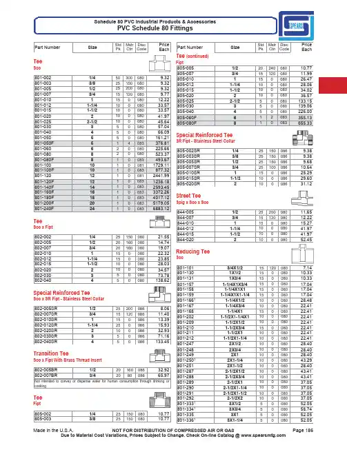
Pk Ctn Code Each TeeSoc801-0021/4503000809.32 801-0033/8251500809.32 801-0051/2252000809.32 801-0073/4151200809.77 801-010*********.22 801-0121-1/410008033.57 801-0151-1/210008033.57 801-020*********.97 801-0252-1/210008045.64 801-03035008057.04 801-04045008066.09 801-050550080161.21 801-050F514083376.81 801-060620080225.66 801-080820080523.37 801-080F810083493.67 801-10010100811729.11 801-100F1010083877.32 801-12012100812441.99 801-120F12100831236.18 801-140F14100832593.45 801-160F16100833372.26 801-180F181********.12 801-200F20100835179.05 801-240F24100836883.12 TeeSoc x Fipt802-0021/42515008021.55 802-0051/22016008014.74 802-0073/42016008019.07 802-010*********.32 802-0121-1/415008023.85 802-0151-1/210008028.03 802-020*********.57 802-03035008073.78 802-040450080138.62 Special Reinforced TeeSoc x SR Fipt - Stainless Steel Collar802-005SR1/2252000868.06 802-007SR3/41512008611.40 802-010SR115008613.39 802-012SR1-1/425008615.93 802-020SR210008632.93 802-030SR35008671.16 802-040SR450086133.45 Transition TeeSoc x Fipt With Brass Thread Insert802-005BR1/22016008632.92 802-007BR3/4208008665.97 Not intended to convey or dispense water for human consumption through drinking or cookingTeeFipt805-0021/42515008010.77 805-0033/82515008010.77Pk Ctn Code Each Tee (continued)Fipt805-0051/22024008010.77 805-0073/41512008011.99 805-010*********.47 805-0121-1/410008028.06 805-0151-1/210008034.02 805-020*********.57 805-0252-1/250080133.15 805-030350080139.06 805-040450080226.00 805-060F612083355.13 805-080F810083655.33 Special Reinforced TeeSR Fipt -Stainless Steel Collar805-002SR1/4251500869.38 805-003SR3/8251500869.38 805-005SR1/2251500869.68 805-007SR3/42510008610.64 805-010SR115008625.29 805-015SR1-1/210008629.60 805-020SR210008631.12 Street TeeSpig x Soc x Soc844-0051/22520008011.65 844-0073/41512008012.22 844-010*********.27 844-0121-1/410008041.97 844-0151-1/210008041.97 844-020*********.45 Reducing TeeSoc801-1013/4X1/2151200807.14 801-1301X1/215008010.33 801-1311X3/415008010.33 801-1571-1/4X1X3/415008017.04 801-1581-1/4X1X115008017.04 801-1591-1/4X1X1-1/415008017.04 801-16611-1/4X1/210008028.48 801-1671-1/4X3/410008022.41 801-1681-1/4X115008022.41 801-2021-1/2X1-1/4X110008022.41 801-2091-1/2X1/210008022.41 801-2101-1/2X3/415008022.41 801-2111-1/2X110008022.41 801-2121-1/2X1-1/410008022.41 801-2472X1/210008028.40 801-2482X3/410008028.40 801-2492X110008028.40 801-25012X1-1/410008043.29 801-2512X1-1/210008028.40 801-2872-1/2X1/210008043.41 801-2882-1/2X3/410008043.41 801-2892-1/2X110008037.05 801-2902-1/2X1-1/410008037.05 801-2912-1/2X1-1/210008037.05 801-2922-1/2X210008037.05 801-33313X1/25008052.05 801-33413X3/45008058.74 801-3353X15008052.05 801-33613X1-1/45008052.05Pk Ctn Code Each Reducing Tee (continued)Soc801-3373X1-1/25008052.05 801-3383X25008052.05 801-3393X2-1/26008052.05 801-41614X3/450080102.95 801-41714X150080102.95 801-41814X1-1/450080102.95 801-4194X1-1/25008084.11 801-4204X25008084.11 801-42114X2-1/250080151.42 801-4224X35008084.11 801-42614X640080412.22 801-482F5X1-1/415083222.99 801-484F5X1-1/215083227.20 801-486F5X215083227.20 801-487F5X2-1/214083259.08 801-488F5X313083267.56 801-49015X440080250.94 801-490F5X414083285.62 801-52316X1/240080218.75 801-5256X140080168.07 801-52616X1-1/440080218.75 801-52716X1-1/240080218.75 801-5286X240080168.07 801-52916X2-1/240080218.57 801-5306X340080168.07 801-5326X450080225.66 801-533F6X513083475.01 801-537F6X10100831848.89 801-539F6X12100832052.88 801-57318X1/220080642.20 801-57518X120080642.59 801-57818X220080611.02 801-578F8X212083419.13 801-57918X2-1/220080672.29 801-579F8X2-1/212083423.02 801-58018X320080611.02 801-580F8X312083427.76 801-58218X420080611.02 801-582F8X412083449.80 801-583F8X510083608.07 801-5858X620080523.37 801-59118X12100813733.67 801-621F10X212083629.60 801-622F10X2-1/210083657.58 801-623110X3100811611.03 801-623F10X310083675.24 801-624110X4100811611.03 801-624F10X410083699.53 801-625F10X510083752.27 801-626110X6100811521.63 801-626F10X610083791.13 801-628110X8100811790.76 801-628F10X810083887.53 801-632F10X12100832186.24 801-661F12X210083814.14 801-662F12X2-1/210083849.28 801-663F12X310083876.99 801-664112X4100812920.84 801-664F12X410083930.33 801-665F12X510083974.92 801-666112X6100812755.74 801-666F12X6100831027.26 801-66812X8100812263.74 801-668F12X8100831102.11 801-670112X10100813031.45Pk Ctn Code Each Reducing Tee (continued)Soc801-670F12X10100831224.68 801-678F12X181********.97 801-691F14X2100831020.11 801-692F14X2-1/2100831071.69 801-693F14X3100831252.40 801-694F14X4100831380.16 801-696F14X6100831489.88 801-698F14X8100831566.69 801-700F14X10100831673.75 801-702F14X12100831767.38 801-706F14X16100835718.92 801-751F16X2100831308.13 801-752F16X2-1/2100831391.37 801-753F16X3100831411.31 801-754F16X4100831544.03 801-756F16X6100831642.60 801-758F16X8100831824.44 801-760F16X10100831977.71 801-762F16X12100832179.49 801-764F16X14100832513.14 801-781F18X2100831503.78 801-783F18X3100831830.92 801-784F18X4100832811.82 801-786F18X6100833045.48 801-788F18X8100833175.88 801-790F18X10100833402.34 801-792F18X12100833595.58 801-794F18X14100833821.21 801-796F18X16100833870.03 801-814F20X4100833448.54 801-816F20X6100833641.28 801-818F20X8100833753.20 801-820F20X10100833908.31 801-822F20X12100834190.71 801-824F20X14100834493.97 801-826F20X16100834816.71 801-828F20X181********.75 801-904F24X4100834293.87 801-906F24X6100834458.31 801-908F24X8100834574.25 801-910F24X10100834855.74 801-912F24X12100835034.93 801-914F24X14100835242.69 801-916F24X16100835484.55 801-918F24X181********.87 801-920F24X20100836759.89¹Sized with BushingReducing TeeSoc x Fipt802-1013/4X1/21512008013.54 802-1301X1/250008014.07 802-1311X3/415008018.08 802-1661-1/4X1/225008023.01 802-16711-1/4X3/415008023.01 802-1681-1/4X110008045.67 802-2091-1/2X1/225008028.48 802-21011-1/2X3/420008028.48 802-2111-1/2X110008028.48 802-2121-1/2X1-1/410008028.48 802-2472X1/210008032.54 802-2482X3/410008032.54 802-24912X110008043.29Pk Ctn Code Each Reducing Tee (continued)Soc x Fipt802-25012X1-1/410008043.29 802-25112X1-1/210008060.36 802-2872-1/2X1/210008074.92 802-28812-1/2X3/410008074.92 802-28912-1/2X110008074.92 802-29012-1/2X1-1/410008074.92 802-29112-1/2X1-1/210008074.92 802-29212-1/2X210008083.65 802-33313X1/25008058.74 802-33413X3/45008058.74 802-33513X15008070.65 802-33613X1-1/45008070.65 802-33713X1-1/25008070.65 802-33813X25008090.22 802-33913X2-1/250080126.89 802-41514X1/250080103.37 802-41614X3/450080103.37 802-41714X150080103.37 802-41814X1-1/450080103.37 802-41914X1-1/250080103.37 802-42014X250080154.52 802-42114X2-1/250080154.52 802-42214X350080172.98 802-52516X140080240.54 802-52616X1-1/440080240.54 802-52716X1-1/240080240.54 802-52816X240080240.54 802-528F*6X213083438.05 802-52916X2-1/240080240.54 802-53016X340080335.81 802-53216X420080351.83 802-532F*6X414083542.85 802-57818X220080655.62 802-578F8X212083586.67 802-58018X320080655.62 802-580F8X312083586.67 802-58218X420080655.62 802-582F*8X412083650.24 802-621110X2100811674.26 802-621F10X210083712.39 802-623110X3100801674.26 802-623F10X310083770.05 802-624110X4100811674.26 802-624F*10X410083855.49 802-661112X2100812652.85 802-661F12X210083904.88 802-663112X3100812652.85 802-663F12X310083981.88 802-664112X4100812652.85 802-664F12X4100831083.75¹Sized with Bushing* An asterisk (*) appearing after a fabricated fitting part number indicates the item is fiberglass reinforced.Reducing TeeSoc x Fipt x Soc803-0953/4X1/2X3/450008012.69Special Reinforced Reducing TeeSoc x SR Fipt -Stainless Steel Collar802-072SR1/2X1/4251500868.06 802-098SR3/4X1/42510008610.47Pk Ctn Code Each Special Reinforced Reducing Tee (continued)Soc x SR Fipt -Stainless Steel Collar802-101SR3/4X1/250008610.47 802-128SR11X1/4108008624.79 802-130SR1X1/250008612.92 802-131SR1X3/415008624.79 802-164SR11-1/4X1/45008626.43 802-166SR1-1/4X1/225008617.52 802-168SR1-1/4X110008617.87 802-207SR11-1/2X1/410008630.84 802-211SR1-1/2X110008619.35 802-212SR1-1/2X1-1/410008619.35 802-245SR12X1/410008635.62 802-247SR2X1/210008635.62 802-248SR2X3/410008635.62 802-287SR2-1/2X1/210008626.25 802-331SR13X1/45008668.00 802-333SR13X1/25008669.97 802-413SR14X1/45008693.64 802-415SR14X1/250086101.77¹Sized with BushingSpecial Reinforced Reducing TeeSoc x SR Fipt -Stainless Steel Collar x Soc(See also Gauge & Instrument Fittings for additional configurations)803-095SR3/4X1/2X3/415008613.19Transition Reducing TeeSoc x Fipt With Brass Thread Insert802-101BR3/4X1/250008641.08 Not intended to convey or dispense water for human consumption through drinking or cooking90° EllSoc806-0021/425150080 3.31 806-0033/820120080 3.31 806-0051/220240080 3.31 806-0073/420160080 4.22 806-010******* 6.80 806-0121-1/41000809.11 806-0151-1/21000809.76 806-020*********.79 806-0252-1/25008027.59 806-03035008031.01 806-04045008047.16 806-045F4-1/212083216.82 806-050540080120.91 806-050F514083242.08 806-060640080134.19 806-080820080369.86 806-10010100811655.26 806-100F1010083660.59 806-12012100812157.75 806-120F12100831079.76 806-140F14100831377.35 806-160F16100831712.98 806-180F181********.07 806-200F20100832923.53 806-240F24100834489.44 806-33813X25008076.01 806-42214X350080113.54¹Sized with BushingPk Ctn Code Each90° Ell SweepSoc x Soc806-005S1/2251500808.24 806-007S3/42510008010.67 806-010S125008017.19 806-012S1-1/425008022.73 806-015S1-1/225008024.43 806-020S225008029.60Long Sweep 90° EllSoc806-005LSF1/212508328.57 806-007LSF3/412508332.06 806-010LSF112508335.84 806-012LSF1-1/412508360.62 806-015LSF1-1/212508361.39 806-020LSF211008366.37 806-025LSF2-1/217083113.97 806-030LSF315083124.34 806-040LSF414083139.43 806-060LSF612083213.55 Not Listed for Electrical Conduit Use90° EllSoc x Fipt807-0021/42545008013.00 807-0033/82515008013.00 807-0051/22024008013.00 807-0073/42016008015.29 807-010*********.54 807-0121-1/410008019.07 807-0151-1/210008022.75 807-020*********.47 807-03035008070.39 807-040450080132.74 807-0601630080307.99¹Thread outlet sized with Female AdapterSpecial Reinforced 90° EllSoc x SR Fipt -Stainless Steel Collar807-005SR1/2202400867.72 807-007SR3/47500869.18 807-010SR15000869.28 807-012SR1-1/425008612.47 807-015SR1-1/210008615.41 807-020SR210008617.68 807-030SR35008644.89 807-040SR45008679.32Transition 90° EllSoc x Fipt With Brass Thread Insert807-005BR1/22024008628.92 807-007BR3/42016008651.19 Not intended to convey or dispense water for human consumption through drinking or cooking90° EllFipt808-0021/4254500808.20 808-0033/8251500808.20Pk Ctn Code Each 90° Ell (continued)Fipt808-0051/2201200807.65 808-0073/4202400809.53 808-01011512008011.99 808-0121-1/410008012.92 808-0151-1/210008018.32 808-020*********.64 808-0252-1/25008080.37 808-030350080129.60 808-040450080228.04 90° Street EllMipt x Fipt812-0021/45030008017.63 812-00511/22024008014.64 812-0101120008022.60 812-01211-1/410008025.97 812-01511-1/210008042.56¹Sized with AdapterSpecial Reinforced 90° EllSR Fipt -Stainless Steel Collar808-003SR3/825150086 4.51 808-005SR1/220120086 4.51 808-007SR3/420120086 5.67 808-010SR1500086 6.60 808-012SR1-1/42500867.05 808-015SR1-1/210008611.00 808-020SR210008612.39 90° Street EllSpig x Soc809-0051/250200080 4.14 809-0073/4500080 5.28 809-010********.52 809-0121-1/425008011.40 809-0151-1/210008012.22 809-020*********.75 809-03035008041.38 809-04044008062.87 809-060610080178.93 809-080820080493.16 809-10010100812206.41 809-12012100812876.12 Reducing 90° EllSoc x Fipt807-1013/4X1/210600807.88 807-13011X1/2108008012.58 807-13111X3/4108008012.58¹Sized with BushingSpecial Reinforced Reducing 90° EllSoc x SR Fipt -Stainless Steel Collar807-101SR3/4X1/25000869.16 807-130SR1X1/250008610.28Pk Ctn Code EachTransition Reducing 90° EllSoc x Fipt With Brass Thread Insert807-101BR3/4X1/22012008636.09 Not intended to convey or dispense water for human consumption through drinking or cooking60° EllSoc824-005F1/21708374.22 824-007F3/41608387.64 824-010F112508395.36 824-012F1-1/411608397.22 824-015F1-1/2116083103.85 824-020F2116083131.75 824-025F2-1/2110083155.11 824-030F314083155.39 824-040F414083199.67 824-060F612083356.59 824-080F812083432.20 824-100F1012083738.44 824-120F1210083964.51 824-140F14100831201.02 824-160F16100831357.04 824-180F181********.19 824-200F20100832651.38 824-240F24100834421.29 45° EllSoc817-0021/42545008011.87 817-0033/82515008011.87 817-0051/220240080 6.22 817-0073/4202400809.51 817-01011512008014.25 817-0121-1/4108008018.15 817-0151-1/210008021.46 817-020*********.83 817-0252-1/25008058.42 817-03035008071.11 817-040450080128.05 817-045F4-1/21208388.71 817-050540080153.20 817-050F514083121.05 817-060640080161.26 817-080820080349.63 817-10010100811100.75 817-100F1012083464.54 817-12012100811419.89 817-120F1210083653.56 817-140F14100831065.27 817-160F16100831304.15 817-180F181********.37 817-200F20100832180.34 817-240F24100832700.68 45° EllFipt819-0021/42545008013.46 819-0033/82515008013.46 819-0051/22012008012.28 819-0073/41012008013.20 819-01011012008016.56Pk Ctn Code Each 45° Ell (continued)Fipt819-0121-1/4108008025.26 819-0151-1/210008031.76 819-020*********.08 819-0252-1/25008093.16 819-030350080149.84 819-040450080215.01 Special Reinforced 45° EllSR Fipt -Stainless Steel Collar819-007SR3/4101200867.76 45° Street EllSpig x Soc827-0051/250400080 6.22 827-0073/45000809.51 827-010*********.25 827-0121-1/425008018.15 827-0151-1/225008021.46 827-020*********.83 827-0252-1/212008036.69 827-030310008071.11 827-040450080128.05 827-050F512083154.92 827-060640080189.69 827-080820080411.35 827-10010100811295.03 827-12012100811670.46 827-140F1410083983.22 827-160F16100831577.21 827-180F181********.17 827-200F20100832319.57 827-240F24100833688.31 30° EllSoc815-005F1/212508326.75 815-007F3/412508326.94 815-010F113008329.47 815-012F1-1/411508331.92 815-015F1-1/212508332.36 815-020F212508335.28 815-025F2-1/211808339.09 815-030F312008342.65 815-040F41608355.93 815-045F4-1/211808385.19 815-050F512083102.17 815-060650080189.69 815-080F813083171.15 815-100F1012083303.33 815-120F1212083443.33 815-140F1410083678.69 815-160F1610083907.22 815-180F181********.67 815-200F20100832020.52 815-240F24100832410.66 22-1/2° EllSoc816-0051/2202400807.34 816-0073/42024008011.20Pk Ctn Code Each 22-1/2° Ell (continued)Soc816-01012016008016.78 816-010F112508316.18 816-015F1-1/212508328.22 816-0121-1/420008021.36 816-0151-1/220008025.25 816-020*********.71 816-0252-1/25008067.20 816-025F2-1/211808339.09 816-03035008083.84 816-040440080150.66 816-045F4-1/211808385.19 816-050F518083102.17 816-060640080189.69 816-060F618083104.56 816-080840080411.35 816-080F814083171.15 816-100F1012083303.33 816-120F1212083443.33 816-140F1410083678.69 816-160F1610083907.22 816-180F181********.17 816-200F20100832020.52 816-240F24100832410.6622-1/2° Street EllSpig x Soc842-0051/2504000807.62 842-0073/450008011.71 842-010*********.40 842-0121-1/420008022.91 842-0151-1/225008025.97 842-020*********.71 842-0252-1/25008085.38 842-03035008093.73 842-040440080164.84 842-040F415084105.02 842-060660080234.28 842-060F616083131.75 842-080812080506.54 842-080F814083173.88 842-100F1010083355.36 842-120F1212084463.0315° EllSoc818-005F1/212508326.75 818-007F3/412308326.94 818-010F112008329.47 818-012F1-1/415008331.92 818-015F1-1/212508332.36 818-020F212508335.28 818-025F2-1/2118083115.19 818-030F313508342.65 818-040F412008355.93 818-045F4-1/211808385.19 818-050F512083102.17 818-060F618083104.56 818-080F814083171.15 818-100F1012083303.33 818-120F1212083443.33 818-140F1410083678.69 818-160F1610083907.22 818-180F181********.17Pk Ctn Code Each 15° Ell (continued)Soc818-200F20100832020.52 818-240F24100832410.66 11-1/4° EllSoc811-005F1/215208326.75 811-007F3/415208326.94 811-010F115008329.47 811-012F1-1/412608331.92 811-0151-1/225008026.68 811-020*********.71 811-025F2-1/212508339.09 811-030310008083.84 811-040440080150.66 811-045F4-1/211808385.19 811-050F514083102.17 811-060F6110083104.56 811-080F814083171.15 811-100F1012083303.33 811-120F1212083443.33 811-140F1410083678.69 811-160F1610083907.22 811-180F181********.17 811-200F20100832020.52 811-240F24100832410.66 WyeSoc1/2" -2" -235 psi Maximum Internal Pressure Rating @ 73°F (23°C)2-1/2" -6" -150 psi Maximum Internal Pressure Rating @ 73°F (23°C) 8" -Larger & All Fabricated Sizes -100 psi Maximum Internal Pressure Rating @ 73°F (23°C)875-0051/22510008013.68 875-0073/425008014.38 875-010*********.01 875-0121-1/420008035.28 875-0151-1/220008035.28 875-0202100080101.22 875-02512-1/240080461.20 875-030350080325.38 875-040440080403.17 875-050F*512083630.71 875-060620080550.66 875-0808100801107.40 875-080F810083853.29 875-100F*10100831338.99 875-120F*12100831701.91 875-140F*14100832842.43 875-160F*16100833733.88 875-180F*181********.18 875-200F*20100835591.94 875-240F*24100837442.15¹Sized with Bushing* An asterisk (*) appearing after a fabricated fitting part number indicates the item is fiberglass reinforced.Pk Ctn Code Each Reducing WyeSoc1/2" -2" -235 psi Maximum Internal Pressure Rating @ 73°F (23°C)3" -6" -150 psi Maximum Internal Pressure Rating @ 73°F (23°C)8" -Larger & All Fabricated Sizes -100 psi Maximum Internal Pressure Rating @ 73°F (23°C)875-10113/4X1/225008016.60 875-13011X1/220008029.11 875-13111X3/420008029.11 875-16611-1/4X1/220008044.84 875-16711-1/4X3/420008044.84 875-16811-1/4X120008044.84 875-20911-1/2X1/220008048.03 875-21011-1/2X3/420008048.03 875-21111-1/2X120008048.03 875-21211-1/2X1-1/420008048.03 875-24712X1/2100080120.41 875-24812X3/4100080120.41 875-24912X1100080120.41 875-25012X1-1/4100080120.41 875-25112X1-1/2100080120.41 875-29212-1/2X2-1/2X240080468.76 875-33513X150080379.27 875-33613X1-1/450080379.27 875-33713X1-1/250080379.27 875-33813X240080379.27 875-33913X2-1/250080379.27 875-4204X240080476.83 875-420F*4X215083397.41 875-42114X2-1/240080528.54 875-421F*4X2-1/214083444.12 875-42214X340080476.83 875-52516X150080584.64 875-52816X250080519.19 875-528F*6X213083408.28 875-53016X350080519.19 875-530F*6X312083443.57 875-5326X450080419.66 875-57818X2100801448.65 875-578F*8X212083660.56 875-579F*8X2-1/212083675.37 875-58018X3100801448.65 875-580F*8X312083670.95 875-58218X4100801448.65 875-582F*8X412083711.42 875-58518X6100801351.33 875-585F*8X610083838.92 875-621F*10X210083889.24 875-622F*10X2-1/210083895.43 875-623F*10X310083906.56 875-624F*10X410083988.04 875-625F*10X5100831107.33 875-62610X6100811564.51 875-626F*10X6100831124.31 875-62810X8100811991.86 875-628F*10X8100831300.27 875-661F*12X210083986.82 875-662F*12X2-1/2100831075.84 875-663F*12X3100831177.29 875-664F*12X4100831246.79 875-666F*12X6100831421.92 875-668F*12X8100831557.75 875-670F*12X10100831650.80 875-694F*14X4100831542.98 875-696F*14X6100831632.80Pk Ctn Code Each Reducing Wye (continued)Soc875-698F*14X8100831670.46 875-700F*14X10100831865.06 875-702F*14X12100832113.86 875-754F*16X4100831680.47 875-756F*16X6100831687.76 875-758F*16X8100831904.77 875-760F*16X10100832144.28 875-762F*16X12100832336.28 875-764F*16X14100832705.55 875-784F*18X4100833016.78 875-786F*18X6100833406.48 875-788F*18X8100833533.01 875-790F*18X10100833797.31 875-792F*18X12100833811.79 875-794F*18X14100834116.92 875-796F*18X16100834145.94 875-814F*20X4100833727.95 875-816F*20X6100834017.12 875-818F*20X8100834245.20 875-820F*20X10100834388.98 875-822F*20X12100834546.60 875-824F*20X14100834908.17 875-826F*20X16100835314.37 875-828F*20X181********.26 875-904F*24X4100834638.11 875-906F*24X6100834797.68 875-908F*24X8100834920.49 875-910F*24X10100835143.16 875-912F*24X12100835470.07 875-914F*24X14100835682.24 875-916F*24X16100836062.14 875-918F*24X181********.88 875-920F*24X20100837318.35¹Sized with Bushing* An asterisk (*) appearing after a fabricated fitting part number indicates the item is fiberglass reinforced.Double WyeSoc100 psi Maximum Internal Presure Rating @ 73°F (23°C)876-020F*214083334.67 876-030F*314083421.77 876-040F*412083765.93 876-060F*610083895.23 876-080F*8100831066.61 876-100F*10100831900.60 876-120F*12100832676.48 For larger sizes please contact your Regional Spears® Distribution Center. Reducing Double WyeSocSize 3" is 150 psi, all Fabricated Sizes-100 psi Maximum Internal Pressure Rating @ 73°F (23°C)876-3383X250080406.99 876-420F*4X212083531.52 876-421F*4X2-1/212083601.79 876-422F*4X312083622.46 876-528F*6X212083625.44 876-529F*6X2-1/212083653.28 876-530F*6X312083657.53 876-532F*6X410083783.78 876-578F*8X212083806.75Pk Ctn Code Each Reducing Double Wye (continued)Soc876-579F*8X2-1/212083844.83 876-580F*8X310083849.99 876-582F*8X410083877.41 876-585F*8X610083990.69 876-621F*10X2100831075.73 876-622F*10X2-1/2100831157.96 876-623F*10X3100831164.83 876-624F*10X4100831209.04 876-626F*10X6100831265.54 876-628F*10X8100831626.46 876-661F*12X2100831201.98 876-662F*12X2-1/2100831273.29 876-663F*12X3100831293.39 876-664F*12X4100831377.71 876-666F*12X6100831598.79 876-668F*12X8100831909.69 876-670F*12X10100832178.07 * An asterisk (*) appearing after a fabricated fitting part number indicates the item is fiberglass reinforced.For larger sizes please contact your Regional Spears® Distribution Center.CrossSoc820-0021/42515008045.94 820-0051/250008045.94 820-0073/450008048.35 820-010*********.61 820-0121-1/425008067.93 820-0151-1/225008073.23 820-020*********.67 820-0252-1/2100080123.63 820-030350080154.20 820-040430080268.29 820-060F610083644.71 820-080F810083942.69 820-100F10100831520.48 820-120F12100832141.20 820-140F14100833441.27 820-160F16100833900.04 820-180F181********.77 820-200F20100835956.54 820-240F24100838950.91 Reducing CrossSoc820-10113/4X1/250008053.26 820-13011X1/225008069.00 820-1311X3/420008069.00 820-16611-1/4X1/225008066.27 820-1671-1/4X3/425008061.15 820-16811-1/4X125008087.14 820-20911-1/2X1/220008098.83 820-2101-1/2X3/415008098.83 820-21111-1/2X125008098.83 820-21211-1/2X1-1/425008098.83 820-24712X1/2100080126.80 820-24812X3/4100080126.80 820-24912X1100080126.80 820-25012X1-1/4100080126.80 820-25112X1-1/2100080126.80 820-2892-1/2X1150080126.80 820-29012-1/2X1-1/4100080185.73Pk Ctn Code Each Reducing Cross (continued)Soc820-29112-1/2X1-1/2100080185.73 820-29212-1/2X240080185.73 820-33513X140080251.86 820-33613X1-1/440080251.86 820-33713X1-1/240080251.86 820-33813X240080251.86 820-33913X2-1/240080251.86 820-42014X230080404.64 820-420F*4X214083395.17 820-42214X330080404.64 820-528F6X214083500.35 820-530F6X312083526.02 820-532F6X412083626.97 820-533F*6X512083743.35 820-578F8X210083645.65 820-580F8X310083679.67 820-582F8X410083701.95 820-585F8X610083758.55 820-621F10X210083859.47 820-622F10X2-1/210083883.56 820-623F10X310083931.92 820-624F10X410083967.35 820-626F10X6100831012.33 820-628F10X8100831301.89 820-661F12X210083961.58 820-663F12X3100831035.99 820-664F12X4100831102.59 820-666F12X6100831280.39 820-668F12X8100831529.51 820-670F12X10100831040.24 820-691F14X2100831379.79 820-693F14X3100831484.94 820-694F14X4100831630.41 820-696F14X6100831800.81 820-698F14X8100832048.53 820-700F14X10100832366.88 820-702F14X12100832677.14 820-751F16X2100831726.16 820-753F16X3100831858.93 820-754F16X4100832062.17 820-756F16X6100832230.31 820-758F16X8100832494.58 820-760F16X10100832718.33 820-762F16X12100833053.15 820-764F16X14100833823.62 820-784F18X4100832910.95 820-786F18X6100833038.26 820-788F18X8100833260.62 820-790F18X10100833482.81 820-792F18X12100833647.03 820-794F18X14100833864.17 820-796F18X16100834026.45 820-814F20X4100833650.09 820-816F20X6100834204.38 820-818F20X8100834251.60 820-820F20X10100834545.29 820-822F20X12100834873.76 820-824F20X14100835442.01 820-826F20X16100835548.12 820-828F20X181********.82 820-904F24X4100834357.68 820-906F24X6100834631.88 820-908F24X8100834812.75 820-910F24X10100834881.51 820-912F24X12100835104.49Pk Ctn Code Each Reducing Cross (continued)Soc820-914F24X14100836073.65 820-916F24X16100836486.02 820-918F24X181********.09 820-920F24X20100838898.58¹Sized with BushingCouplingSoc829-0021/4254500809.57 829-0033/8251500809.57 829-0051/225150080 5.98 829-0073/4253000808.09 829-0101252000808.32 829-0121-1/4108008012.67 829-0151-1/2108008013.66 829-020*********.67 829-0252-1/210008036.11 829-03035008041.46 829-04045008051.93 829-050550080102.98 829-050F51508364.27 829-060640080111.76 829-080840080152.09 829-1001010081522.01 829-100F1010083175.80 829-1201210081601.61 829-120F1210083202.64 829-1401410081765.42 829-140F1410083405.21 829-160F1610083481.75 829-180F1810083949.59 829-200F20100831170.80 829-240F24100831285.55 Grooved Coupling AdapterGroove x Soc833-0121-1/4106008016.60 833-0151-1/2108008018.55 833-0202108008021.58 833-0252-1/25008046.60 833-03035008055.55 833-04045008063.04 833-050F517084121.01 833-060650080136.12 833-080F814084156.09 833-100F1010084191.68 833-120F1210084258.95 CouplingFipt830-0021/4254500807.17 830-0033/8251500807.17 830-0051/225150080 6.69 830-0073/4253000809.54 830-0101159008010.24 830-0121-1/41012008012.67 830-0151-1/2108008028.20 830-020*********.60 830-0252-1/25008070.66 830-03035008082.86 830-040450080143.48Pk Ctn Code Each Coupling (continued)Fipt830-060F618083180.83 830-080F816083265.92 830-100F1012083361.68 Special Reinforced CouplingSR Fipt - Stainless Steel Collar830-005SR1/225150086 3.69 830-007SR3/425150086 5.25 830-010SR125200086 5.61 830-012SR1-1/410120086 6.99 830-015SR1-1/2108008615.47 830-020SR210008616.22 Reducer CouplingSoc829-1013/4X1/2504000807.32 829-1301X1/22520008010.22 829-1311X3/42520008010.67 829-1661-1/4X1/225008021.67 829-1671-1/4X3/425008021.67 829-1681-1/4X125008021.67 829-2091-1/2X1/225008022.68 829-2101-1/2X3/425008022.68 829-2111-1/2X125008022.68 829-2121-1/2X1-1/425008028.03 829-2472X1/225008025.58 829-2482X3/4108008025.58 829-2492X116008025.58 829-2502X1-1/4104008025.58 829-2512X1-1/2104008025.58 829-2912-1/2X1-1/210008034.12 829-2922-1/2X210008034.12 829-33513X18008078.02 829-33613X1-1/46008078.02 829-33713X1-1/28008078.02 829-3383X28008062.83 829-3393X2-1/25008089.59 829-339F3X2-1/219083109.27 829-41614X3/460080129.75 829-41714X160080129.75 829-41914X1-1/260080129.75 829-4204X260080119.78 829-4214X2-1/240080119.78 829-4224X340080118.37 829-460F4-1/2X412008378.36 829-487F5X2-1/216083116.34 829-488F5X316083112.79 829-490F5X41808360.84 829-491F5X4-1/211008385.89 829-52816X260080296.38 829-52916X2-1/240080355.41 829-53016X3120080299.40 829-530F6X3110083111.73 829-5326X440080241.43 829-534F6X4-1/21508397.68 829-533F6X515083102.43 829-579F8X2-1/216083309.23 829-580F8X316083283.37 829-582F8X416083264.44 829-583F8X514083290.69 829-5858X620080731.23 829-621F10X212083456.13 829-623F10X312083427.03Pk Ctn Code Each Reducer Coupling (continued)Soc829-624F10X412083403.03 829-625F10X514083366.45 829-62610X610081856.06 829-626F10X614083330.28 829-62810X810081856.06 829-663F12X312083658.40 829-664F12X412083562.44 829-665F12X512083521.81 829-666F12X610083486.53 829-66812X810081974.12 829-668F12X810083376.71 829-670F12X1010083254.49 829-691F14X210083981.38 829-694F14X410083819.47 829-696F14X610083692.18 829-698F14X810083633.39 829-700F14X1010083619.49 829-702F14X1210083371.57 829-754F16X4100831216.69 829-756F16X6100831100.40 829-758F16X810083966.45 829-760F16X1010083858.45 829-762F16X1210083723.59 829-764F16X1410083549.29 829-783F18X3100832640.07 829-784F18X4100832567.20 829-786F18X6100832399.75 829-788F18X8100832272.17 829-790F18X10100832055.42 829-792F18X12100831691.86 829-794F18X14100831145.33 829-796F18X1610083977.80 829-814F20X4100832541.55 829-816F20X6100832340.06 829-818F20X8100832236.65 829-820F20X10100832158.20 829-822F20X12100831867.04 829-824F20X14100831862.11 829-826F20X16100831710.54 829-828F20X181********.55 829-904F24X4100834065.45 829-906F24X6100834003.55 829-908F24X8100833916.79 829-910F24X10100833822.32 829-912F24X12100833477.16 829-914F24X14100833207.22 829-916F24X16100832922.93 829-918F24X181********.89 829-920F24X20100832520.93¹Sized with BushingEccentric Reducer CouplingSoc829-101FE3/4X1/212508338.56 829-130FE1X1/211608327.05 829-131FE1X3/411508339.69 829-168FE1-1/4X111208331.46 829-209FE1-1/2X1/212008349.82 829-210FE1-1/2X3/412508351.56 829-212FE1-1/2X1-1/412008332.67 829-249FE2X112508346.59 829-250FE2X1-1/412508343.29 829-251FE2X1-1/211008341.31 829-290FE22-1/2X1-1/411008364.17Pk Ctn Code Each Eccentric Reducer Coupling (continued)Soc829-291FE22-1/2X1-1/212008362.38 829-292FE2-1/2X211008348.17 829-335FE23X111008363.21 829-336FE23X1-1/411008360.88 829-337FE23X1-1/211008358.49 829-338E3X215008062.83 829-338FE3X212008337.36 829-339FE3X2-1/2110083121.31 829-417FE34X1118083153.63 829-418FE34X1-1/416083150.91 829-419FE34X1-1/216083146.11 829-420FE24X2110083102.01 829-421FE24X2-1/21608385.06 829-422FE4X311008377.15 829-490FE5X418083102.66 829-528FE36X216083180.80 829-529FE36X2-1/212083165.03 829-530FE26X316083159.27 829-532FE6X415083115.31 829-533FE6X515083106.34 829-575FE58X110083368.84 829-577FE58X1-1/210083360.56 829-578FE48X210083320.35 829-580FE38X312083244.15 829-582FE28X412083199.43 829-583FE28X512083199.01 829-585FE8X614083153.36 829-624FE310X410083337.48 829-625FE310X510083384.21 829-626FE210X612083286.43 829-628FE10X812083264.67 829-664FE412X410083516.08 829-666FE312X610083424.73 829-668FE212X810083366.94 829-670FE12X1012083234.55 829-696FE314X610083840.68 829-698FE214X810083691.34 829-700FE14X1010083573.39 829-702FE14X1210083368.36 829-756FE416X6100831553.20 829-758FE316X8100831422.29 829-760FE216X10100831034.67 829-762FE216X1210083918.62 829-764FE16X1410083711.53 829-786FE518X6100832144.06 829-788FE418X8100832052.44 829-790FE318X10100831917.95 829-792FE318X12100831711.92 829-794FE218X14100831411.37 829-796FE18X16100831377.17。
PVC管材挤出生产操作规程1、目的为使PVC-U管材生产过程规范化、条理化、合理化,进而让操作人员在工作中能有所依据二制定本工作文件。
2、范围本规定适用于生产部所有的技术和操作人员。
3、术语和定义(无)4、职责4.1生产操作人员必须按照管材、管件操作规程的生产工艺流程来进行操作。
4.2生产班长、技术员根据《生产计划作业令》负责管材、管件生产工艺过程的指导、监督工作。
5、内容5.1加热、挤出作业指导5.1.1开机前维修人员对主机各操作单元、主要部件进行全面弄检修。
5.1.1.1检查主机齿轮箱,减速箱的油门是否正常。
5.1.1.2检查主机和电器各部分是否工作正常,并检查排水是否打开,压缩空气压力是否正常。
5.1.1.3检查主机防罩是否清洁。
5.1.1.4检查螺杆冷却油路是否畅通。
5.1.1.5检查所有操作开关的灵敏度及调速器是否为零,急停是否归位。
5.1.2 模具工负责对模具进行更换。
5.2.1按要求装好生产模头、定型套及冷却箱两端密封胶垫,并调整好水箱内支架高度和定型套的高度基本一致。
5.2.2模具维修人员对模头的加热圈进行细致的检查确认正常后方可交付操作人员使用。
5.2.3操作人员确定主机正常后,按以下步骤开机。
5.2.3.1开总电源开关,打开挤出机螺杆油泵和上水阀门。
确定模具合适,喷头顺利无堵塞,托轮高度合适,真空胶垫能堵住真空,牵引机压力适中,切割机夹块,进刀合适,扩口机正常。
5.3.3.2接通挤出机加热电源开关,设定加热段温度、螺杆有温为70℃,其余各段为130℃(注:小模加热1小时,大模加热1.5小时)5.3.3.3当各段温度达到上面设定值时,将各加热段温度达到150℃,对新更换的模具应再次拧紧螺栓。
5.3.3.4各加热段达到150℃时,再将各温度设定到生产所需数据略低5-10℃,各段温度不能低于150℃。
(注加温0.5小时)5.3.3.5启动双螺杆,并缓慢均匀开始加清机料。
螺杆转速在0-5r/min负载不能超过30%,油泵温度设为90℃.5.3.3.6依据温度显示数据并按湿度制定物料到达位置并逐渐增加转速。
All dimensions in charts and on drawings are in inches. Dimensions shown in parentheses are in millimeters unless otherwise specified.Fig. 74 - TOLCO structural attachment for branch line restraint assembly (UL listed)Eaton’s B-Line series seismic bracing components are designed to be compatible only with other B-Line series bracing components, resulting in a listed seismic bracing assembly. Eaton B-Line Division warranty for seismic bracing components will be the warranty provided in Eaton B-Line Division standard terms and conditions of sale made available by Eaton, except that, in addition to the other exclusions from Eaton B-Line Division warranty, Eaton makes no warranty relating to B-Line series seismic bracing components that are combined with products not provided by Eaton.Size Range: 3⁄8" and 1⁄2" all threaded rod (ATR)Material: SteelFunction: Structural attachment for restraint (sway brace) or hanger assembly Features: The Fig. 74 has multiple sized fastener holes to accommodate multiple types of fasteners for various types of structures (concrete, wood and steel) see table below. Barrel rolls freely to allow installation angles from 0° to 90° from the mounting surface. Multiple holes to allow various fasteners to attach to the structure. Larger hole accommodates 3⁄8" (9.5mm) fastener, and smaller hole accommodates 1⁄4" (6.4mm) or #10 fasteners. It is UL listed both as a restraint and as a hanger attachment for up to 4" (IPS) pipe size.Installation Instructions: Install all threaded rod (ATR), (brace member) to TOLCO ™ Fig. 74 structural attachment. Bottom out 1/2" ATR in barrel nut or thread 3/8" ATR through to back side of barrel nut for proper engagement. Install Fig. 74 structuralattachment to the building structure. Follow fastener manufacturer and NFPA 13 guidelines to install appropriate fastener for the structural type (i.e. concrete, wood, steel). For more information visit our website for the most up to date instructions sheets.Approvals: Underwriters Laboratories Listed in the USA (UL) and Canada (cUL).For FM Approval information refer to FM Approved page 43.Finish: Zinc plated.Order By:Figure number.Fasteners to use with Fig 74 (Up to 2" IPS pipe size) per NFPA 13 StructureFastener Fastener Fastener NFPA 13 (2013 & 2016) TypeTypeDiameterEmbedment ReferenceAnchors Steel Through Bolt 3/8" N/A 9.1.4.5.1UL Listed Beam Steel Beam Clamp 3/8" N/A Clamp with Retaining Strap Wood (1) 3/8" lag screw 3/8" 2 1/2" 9.1.5.3.1Wood (2) #10 wood screws#101"**Per NFPA 13 (2013) Table 9.3.5.11.8 (a)(b)(c), consult for maximum allowable load information on ATR.‡Max load governed by Fig. 74/77 Max horizontal load.UL listed maximum allowable loads (horizontal)ProductSch. 10, Sch. 40, Dynaflow & CPVC3/8" Rod (9.5mm) 1/2" Rod (12.7mm)Fig. 74 (sway brace)300 lbs. (1.344 kN) 300 lbs. (1.344 kN)Fig. 74 (hanger)1500 lbs. (6.672 kN) 1500 lbs. (6.672 kN)Updated 3-17-22Structural Attachment for Restraint (Sway Brace)WO ABC—Part No.Description WO FIG 74 WO Without screwsAll dimensions in charts and on drawings are in inches. Dimensions shown in parentheses are in millimeters unless otherwise specified.C P V C C l a m p sMaximum Allowable Loads (FM Approved)Fig. 74 - TOLCO structural attachment for sway brace assembly (FM approved)Eaton’s B-Line series seismic bracing components are designed to be compatible only with other B-Line series bracing components, resulting in a listed seismic bracing assembly. Eaton B-Line Division warranty for seismic bracing components will be the warranty provided in Eaton B-Line Division standard terms and conditions of sale made available by Eaton, except that, in addition to the other exclusions from Eaton B-Line Division warranty, Eaton makes no warranty relating to B-Line series seismic bracing components that are combined with products not provided by Eaton.Size Range: 3⁄8" and 1⁄2" all threaded rod (ATR) Material: SteelFunction: Structural attachment for restraint (sway brace) assemblyFeatures: The Fig. 74 has multiple sized fastener holes to accommodate multiple types of fasteners for various types of structures (concrete, wood and steel) see table below. Barrel rolls freely to allow installation angles from 0° to 90° from the mounting surface. Multiple holes to allow various fasteners to attach to the structure. Larger hole accommodates 3⁄8" (9.5mm) fastener, and smaller hole accommodates 1⁄4" (6.4mm) or #10 fasteners. It is UL listed both as a restraint and as a hanger attachment for up to 4" (IPS) pipe size.Installation Instructions: Install all threaded rod (ATR), (brace member) to TOLCO ™Fig. 74 structural attachment. Bottom out 1/2" ATR in barrel nut or thread 3/8" ATR through to back side of barrel nut for proper engagement. Install Fig. 74 structuralattachment to the building structure. Follow fastener manufacturer and NFPA 13 guidelines to install appropriate fastener for the structural type (i.e. concrete, wood, steel). For more information visit our website for the most up to date instructions sheets.Approvals: Approved by FM .For UL Listed information refer to UL Listed page 42.Finish: Zinc plated.Order By: Figure number.Loads shown are axial ASD loads.Fasteners to use with Fig 74 (Up to 2" IPS pipe size) per NFPA 13 Structure Fastener Fastener Fastener NFPA 13 (2013 & 2016) TypeTypeDiameterEmbedment ReferenceAnchors Steel Through Bolt 3/8" N/A 9.1.4.5.1FM Approved Steel Beam Clamp 3/8" N/A Beam Clamp withRetaining Strap Wood (1) 3/8" lag screw 3/8" 2 1/2" 9.1.5.3.1Wood (2) #10 wood #10 1"screwsAll Thread Rod Maximum Restraint Lengths † l/r = 400 NFPA 13 2010, Sec 9.3.6.1 (5) † l/r = 400 NFPA 13 2013 & 2016,Sec 9.3.6.1 (5) & NFPA (2016) TABLE 9.3.11.8(a)(b)(c)(d)(e)(f)**Per NFPA 13 (2013) Table 9.3.5.11.8 (a)(b)(c), consult for maximum allowable load information on ATR.‡Max load governed by Fig. 74/77 Max horizontal load.Structural Attachment for Restraint (Sway Brace)Updated 3-17-22WO ABC—Part No.Description WO FIG 74 WO Without screwsAll dimensions in charts and on drawings are in inches. Dimensions shown in parentheses are in millimeters unless otherwise specified.Function: System attachment for restraint (sway brace) assemblyFeatures: The Fig. 77 is UL Listed to be used with both (IPS) steel and CPVC fire sprinkler pipe, in 1" through 2" diameters. It fits multiple rod diameters allowing for field adjustment if longer brace material is needed. Its sturdy break-off bolt will not strip and verifies proper installation. Its snap on design has many advantages. It can be installed with one-hand, can easily position the brace all thread rod over the top of the pipe being braced or underneath the pipe being braced to accommodate the desired brace angle. It can be fixed in place or moved to a new location by sliding along the pipe or snapping on or off and relocating. An entire prefabricated assembly (Fig. 74 & 77 joined with ATR) can be pre-assembled to save time and labor and later be field installed and adjusted to fit.Installation Instructions: Install TOLCO ™ Fig. 77 system attachment to sprinkler pipe branch line to be restrained. You can position with the rod engagement either above or below the sprinkler pipe. Rod must extend a min. of 1" (25.4) past the edge of the Fig. 77. The attachment can be slid along the pipe to position close to where the Fig. 74 structural attachment will be fastened to the structure. The snap on design allows maximum adjustability during this stage of the installation process. Engage ATR (previously attached to the Fig. 74 structural attachment to the rod engagement portion of the Fig. 77 system attachment. Tighten set bolt on Fig. 77 system attachment until head breaks off verifying proper installation torque. For more i nformation visit our website for the most up to date instructions sheets.Approvals: Underwriters Laboratories Listed in the USA (UL) and Canada (cUL). For FM Approved information refer to FM Approved page 45.Finish: Pre-Galvanized.Order By: Figure number and pipe size.Eaton’s B-Line series seismic bracing components are designed to be compatible only with other B-Line series bracing components, resulting in a listed seismic bracing assembly. Eaton B-Line Division warranty for seismic bracing components will be the warranty provided in Eaton B-Line Division standard terms and conditions of sale made available by Eaton, except that, in addition to the other exclusions from Eaton B-Line Division warranty, Eaton makes no warranty relating to B-Line series seismic bracing components that are combined with products not provided by Eaton.Pipe Attachment for Branch Line Restraint US Patent No. 9,797,527* T hese loads apply to IPS steel, Sch.10, Sch. 40, engineered lightwall piping, and CPVC plastic pipe. Loads shown are axial ASD loads.§ A ll other trademarks are property of their respective owners.† l/r = 400 NFPA 13 2010, Sec 9.3.6.1 (5) † l/r = 400 NFPA 13 2013 & 2016,Sec 9.3.6.1 (5) & NFPA (2016) TABLE 9.3.11.8(a)(b)(c)(d)(e)(f)**Per NFPA 13 (2013) Table 9.3.5.11.8 (a)(b)(c), consult for maximum allowable load information on ATR.‡Max load governed by Fig. 74/77 Max horizontal load.Updated 5-24-21All dimensions in charts and on drawings are in inches. Dimensions shown in parentheses are in millimeters unless otherwise specified.Size Range: 3⁄8" and 1⁄2" all threaded rod (ATR) Material: SteelFunction: System attachment for restraintFeatures: The Fig. 77 is to be used with both (IPS) steel and CPVC fire sprinkler pipe, in 1" through 2" diameters. It fits multiple rod diameters allowing for field adjustment if longer brace material is needed. Its sturdy break-off bolt will not strip and verifies proper installation. Its snap on design has many advantages. It can be installed with one-hand, can easily position the brace all thread rod over the top of the pipe being braced or underneath the pipe being braced to accommodate the desired brace angle. It can be fixed in place or moved to a new location by sliding along the pipe or snapping on or off and relocating. An entire prefabricated assembly (Fig. 74 & 77 joined with ATR) can be pre-assembled to save time and labor and later be field installed and adjusted to fit.Installation Instructions: Install TOLCO ™ Fig. 77 system attachment to sprinkler pipe branch line to be restrained. It can be positioned with the rod engagement either above or below the sprinkler pipe. Rod must extend a min. of 1" past the edge of the Fig. 77. The attachment can be slid along the pipe to position close to where the Fig. 74 structural attachment will be fastened to the structure. The snap on design allows maximum adjustability during this stage of the installation process. Engage ATR (previously attached to the Fig. 74 structural attachment to the rod engagement portion of the Fig. 77 system attachment. Tighten set bolt on Fig. 77 system attachment until head breaks off verifying proper installation torque. For more information visit our website for the most up to date instructions sheets.Approvals: Approved by FM .For UL Listed information refer to UL Listed page 44.Finish: Pre-Galvanized.TOLCO Fig. 77 - System Piping Attachment for Sway Brace Assembly (FM Approved)For CPVC & Steel PipeEaton’s B-Line series seismic bracing components are designed to be compatible only with other B-Line series bracing components, resulting in a listed seismic bracing assembly. Eaton B-Line Division warranty for seismic bracing components will be the warranty provided in Eaton B-Line Division standard terms and conditions of sale made available by Eaton, except that, in addition to the other exclusions from Eaton B-Line Division warranty, Eaton makes no warranty relating to B-Line series seismic bracing components that are combined with products not provided by Eaton.Pipe Attachment for Restraint (Sway Brace) US Patent No. 9,797,527Updated 5-24-21。
Pvc卡打印机使用说明书JF8600是一款热转印PVC卡打印机,同时也属于4色印刷的pvc卡打印机,下面的就有小编给大家介绍一下JF8600这款产品的使用说明及在使用过程中的一些问题。
更换色彩/热印膜1.打开打印机门2.按住盒子按钮,拉出盒子(右:色带盒,左:转印膜盒),去除色带/转印膜3.安装新的色彩/转印膜(1)安装是参照盒子上的粘胶标签(2)把带墨的/转印表面朝外,沿三个轴展开色带/转印膜,并稳稳插入筒管架4.拉进色带,沿导轨插入色带/转印膜.知道听到“咔哒”医生5.关上打印机门,按[RESET]重置打印机注意事项:1.如果打印功能已打开,打印机会被锁住。
从电脑关闭安全功能。
打印后,再从电脑打开安全功能。
2.更换色带/转印膜时,用双手握住盒子3.安装用过的色带时,把色带没有用过的黄色面与盒子标签上所示箭头对齐4.按图所示,把盒子竖放在平整的表面上5.拉紧色带/转印膜否则可因表面褶皱而导致堵塞或者造成色彩不均6.不要用手接触带墨的转印表面(安装时朝外的那一面),处理色带/转印膜时戴上手套7.不要再打印机门上操作,不要再打印机上放置重物或者施加负荷8.安装新的转印膜时,确定至少三条黑线卷到了卷轴上打印卡片1.打开电源2.检查确保卡片插入送卡箱3.打开打印设置屏幕,在[Printers]中选择本打印机4.确保打印机的液晶控制面板上出现[Ready]字样后,开始打印注意事项1.如果您在打印的液晶控制面板上看到[Initializing...]或者[Preheating...]字样,这表示打印机尚未做好准备。
在打印机做好准备前,无法进行打印。
2.在卡片带磁条的一面上打印,可能会造成打印错误,或损坏卡片功能。
如果您要这么做,请事先跟商家进行沟通补充卡片1.把送卡箱的旋钮设置在open上2.上提,取下送卡箱外盖3.对齐卡片方向,把卡片放进打印机4.装上送卡箱外盖注意事项1.如果安全功能已打开,送卡箱会被锁住,从电脑关闭安全功能。
1343Plastic PipeMade in the U.S.A. 1344NOT FOR DISTRIBUTION OF COMPRESSED AIR OR GASProgressive Products from Spears ® Innovation and Technology General InformationPVCPolyvinyl Chlorides (PVC) is one of the most widely used plastic piping materials. PVC is environmentally sound, pro-vides long service life, is light weight and easy to install, has superior corrosion resistance, is cost effective, and widely accepted by codes. PVC pipe is manufactured by extrusion and PVC fittings are manufactured by injection molding or fabrication. PVC is an amorphous thermoplastic mate-rial with physical properties that make it suitable for a wide variety of pressure and non-pressure applications and can be compounded for optimum performance. PVC pipe and fit-tings are used for drain-waste-vent (DWV), sewers, water mains, water service lines, irrigation, conduit, and various industrial installations.Spears ® high quality PVC compounds give optimum chemi-cal and corrosion resistance with a full range of pressure handling capabilities. Spears ® PVC materials are certified by NSF International to applicable standards, including NSF ® Standard 61 for use in potable water service, certified lead-free, and to ASTM STD D1784, Rigid Poly (Vinyl Chloride) (PVC) Compounds and Chlorinated Poly (Vinyl Chloride) (CPVC) Compounds that specifies Cell Classification for minimum physical property requirements. These include res-in type, impact strength, tensile strength, modulus of elastic-ity in tension, heat deflection temperature and flammability. Spears ® minimum PVC Cell Classification is 12454 for rigid (unplasticized) PVC.The ASTM Type and Grade is PVC Type I, Grade I and the typical long and short term strength designation of material for pressure piping is PVC 1120.See Industry Standards and Test Methods, Physical Properties and Chemical Resistance sections for additional information.Spears ®PVC Pipe & Systems Product LinesEverTUFF ® Industrial Schedule 80 Pressure Pipe & Fittings Spears ® Clear PVC Schedule 40 & Schedule 80 Pipe & Fittings Spears ® Low Extractable Ultra Pure Water Piping & Fittings Spears ® PVC Duct & FittingsSpears ® PVC Double Containment Pipe & FittingsSpears ® Supplemental PVC Fittings, Valves & AccessoriesCPVCChlorinated polyvinyl chloride (CPVC) is created by post chlorination of the PVC polymer. This produces up to a 60°F higher heat handling capability than PVC and greater fire resistance, plus a broad range of chemical resistance. CPVC is excellent for use in process piping, hot and cold water service, corrosive waste drainage and other elevated tem-perature applications. CPVC provides relatively low cost compared to alternative materials for similar use. CPVC pipe is manufactured by extrusion and CPVC fittings are manufactured by injection molding or fabrication. Spears ® produces a variety of CPVC pipe, fittings, valves, system accessories and specialty systems.Spears ® high quality CPVC compounds give optimum chemical and corrosion resistance with a full range of pressure handling capabilities. Spears ® CPVC materials are certified by NSF International to applicable standards, including NSF ® Standard 61 for use in potable water service,certified lead-free, and to ASTM STD D1784, Rigid Poly (Vinyl Chloride) (PVC) Compounds and Chlorinated Poly (Vinyl Chloride) (CPVC) Compounds that specifies Cell Classification for minimum physical property requirements. These include resin type, impact strength, tensile strength, modulus of elasticity in tension, heat deflection temperature and flammability. Spears ® minimum CPVC Cell Classifica-tion is 23447 for rigid (unplasticized) CPVC.The ASTM Type and Grade is CPVC Type IV Grade I and the typical long and short term strength designation of material for pressure piping is CPVC 4120.See Industry Standards and Test Methods, Physical Properties and Chemical Resistance sections for additional information.Spears ® CPVC Pipe & Systems Product LinesEverTUFF ® Industrial Schedule 40 & Schedule 80 CPVC Pressure Pipe & FittingsEverTUFF ® CTS CPVC Hot and Cold Water Plumbing Distribution Pipe & FittingsLabWaste™ CPVC Corrosive Waste Drainage System Pipe & FittingsFlameGuard ® CPVC Fire Sprinkler Products Pipe & Fittings Spears ® CPVC Duct & FittingsSpears ® CPVC Double Containment Pipe & FittingsSpears ® Supplemental CPVC Fittings, Valves & AccessoriesPurpose of this ManualSpears ® PVC and CPVC MaterialsThis manual is intended as resource for use by specification engineers, installers, and users in the selection, design and installa-tion of PVC and CPVC systems installed using Spears ® or other pipe products. All information contained within this manual is considered vital to obtain proper system performance and must be read and fully understood before attempting to install these products. If you have any questions about the safe and proper installation of these products, contact Spears ® Manufacturing Company, 15853 Olden Street, Sylmar CA 91342 USA, Telephone (818) 364-1611.The information contained in this publication is based on current information and Product design at the time of publication and is subject to change without notification. Our ongoing commitment to product improvement may result in some variation. No representations, guarantees or warranties of any kind are made as to its accuracy, suitability for particular applications or results to be obtained therefrom. For verification of technical data or additional information not contained herein, please contact Spears ® Technical Services Department [West Coast: (818) 364-1611 — East Coast: (678) 985-1263].“Lead Free” low lead certification – unless otherwise specified, all Spears ® Plastic Piping specified here-in are certified by NSF International to ANSI/NSF ® Standard 61, Annex G and is in compliance with California’s Health & Safety Code Section 116825 (commonly known as AB1953) and Vermont Act 193. Weighted average lead content <=0.25%.。
0.1 质量手册主题容本手册规定了公司的质量方针,引用了质量管理体系程序的核心容,并对质量管理体系的过程顺序和相互作用进行了描述,是公司实施质量管理,开展质量策划、质量控制,质量保证和质量改进活动的纲领性文件。
0.2公司概况本公司创建于 1996 年,现拥有固定资产 2300 万元、占地面积达 9000 平方米,员工 60 余名、管理和技术人员 15 名,配备有先进的全自动吸塑成型生产设备和裁断冲床设备。
2006 年 -2007 年度,公司已经由原来的塑料袋和吸塑加工并举的状态,已经转型为以吸塑加工为主的生产经营状态。
本公司采用环保的 PVC 、 PET 、 PS 、 BOPS 、 PP 等塑料硬片,加工各种超市小商品的塑料包装制品。
主要产品有:吸塑盒,吸卡泡壳 , 插卡泡壳 , 双泡壳 , 对折泡壳 , 吸塑托盘和彩盒的塑料盒。
这些产品应用于小家电、文体用品包装、玩具包装、 IT 电子产品包装、食品包装、五金工具类包装、化妆品包装、汽车零部件包装,建筑防水材料、隔音、塑料吸塑板等行业。
本公司一贯实行实事、用户至上的方针,竭诚为广大用户提供优质产品和优质的服务,愿与国外各公司企业建立广泛的友好合作关系,共同创新、共同发展。
本公司地处市外环线东南角,浦东开发区,拥有得天独厚的地理优势,给本公司和合作伙伴共同发展带来了更大的便利。
0.3组织结构图质量管理体系组织结构图0.4 发布令为了满足吸塑市场的需要和顾客的要求,适应市场的竞争,不断提高公司的吸塑制品质量管理水平,依据 GB/T19001 — 2000 《质量管理体系—要求》标准,我公司制定了《质量手册》,经审定本《质量手册》符合国家有关政策、法律法规和公司的实际情况,于 2005 年 9 月 1 日开始正式批准发布。
但随着公司主营业务的发展变化,公司已由原来的吸塑加工和塑料袋生产并举的状态,转型以吸塑加工为主的经营状态,经公司对《质量手册》改版后,于 2007 年 2 月 1 日发布,并于 2007 年 3 月 1 日开始实施。
SY CONTROL FLEXIBLEPVC INSULATED, BEDDED AND SHEATHED WITHGALVANISED STEEL BRAIDManufactured generally to BS EN 50525-2-11:2011Plain Annealed Flexible Copper Conductors / PVC Insulated / PVC Bedding / GSWB (Galvanised Steel Wire Braid) / PVC Sheathed. 300/500V Conductor : Plain Annealed Copper Class 5 to BS EN 60228 Insulation: PVC Type TI2 to BS EN 50363-3 Bedding: PVC Type TM2 to B EN 50363-4-1 Braiding: GSWB (Galvanised Steel Wire Braid) Sheath:Clear PVC Type TM2 to B EN 50363-4-1Current Ratings: For current ratings refer to table 4F1 and 4F3 ofBS7671 IEE Wiring Regulations Seventeenth Edition.The cable is designed to be used as interconnecting cable for measuring, controlling or regulation in control equipment for assembly and production lines, conveyors and for computer units. It is commonly used in a wide number of industries including building and construction, rail and transport infrastructures, transmission and automation and process control.This cable is also used by electricians in certain fixed installations where only light mechanical stress may occur. This cable can also be used outdoors (but should be protected); however, it is best suited to dry or moist conditions indoors.SY CONTROL FLEXIBLEPVC INSULATED, BEDDED AND SHEATHED WITHGALVANISED STEEL BRAIDSTANDARD CORE COLOURS MINIMUMMAXIMUM MINIMUM 2 CORE OPERATING OPERATING BENDING 3 CORE TEMPERATURETEMPERATURERADIUS4 CORE5 CORE7 CORE+ + BLACK NUMBERED-15°C 70°C6 x ØSY CONTROL FLEXIBLEPVC INSULATED, BEDDED AND SHEATHED WITHGALVANISED STEEL BRAIDR e f e r e n c e N u m b e rN o m i n a l C r o s s S e c t i o n a l A r e a o f C o n d u c t o r (m m ²)N o m i n a l S t r a n d i n g o f C o n d u c t o r (m m )N o m i n a l R a d i a l T h i c k n e s s o f i n s u l a t i o n (m m )N o m i n a l R a d i a l T h i c k n e s s o f b e d d i n g (m m )N o m i n a l R a d i a l T h i c k n e s s o f s h e a t h (m m )A p p r o x i m a t e O v e r a l l D i a m e t e r L o w e r L i m i t (m m )A p p r o x i m a t e O v e r a l l D i a m e t e r U p p e r L i m i t (m m )A p p r o x i m a t e W e i g h t (k g /k m )SY0.752C 0.7524/0.20.50.4 1.07.19.1103SY1.02C 1.032/0.20.50.4 1.07.59.5113SY1.52C 1.530/0.250.50.4 1.07.99.9128SY0.753C 0.7524/0.20.50.4 1.07.99.9115SY1.03C 1.032/0.20.50.4 1.08.310.3126SY1.53C 1.530/0.250.50.4 1.08.910.9146SY2.53C 2.550/0.250.50.4 1.09.711.7184SY4.03C 4.056/0.30.50.4 1.011.013.0247SY6.03C 6.084/0.30.50.6 1.013.015.0322SY7103C 10.080/0.40.60.6 1.015.617.6485SY7163C 16.0126/0.40.60.8 1.019.121.1900SY0.754C 0.7524/0.20.50.4 1.08.410.4130SY1.04C 1.032/0.20.50.4 1.08.910.9145SY1.54C 1.530/0.250.50.4 1.09.511.5170SY2.54C 2.550/0.250.50.4 1.010.512.5218SY4.04C 4.056/0.30.50.4 1.012.014.0299SY6.04C 6.084/0.30.50.6 1.014.216.2394SY7104C 10.080/0.40.60.6117.619.6638SY7164C 16.0126/0.40.60.8 1.021.223.2996SY7254C 25.0196/0.40.80.8 1.025.727.71383SY7354C35.0276/0.40.80.8129.531.51938SY CONTROL FLEXIBLEPVC INSULATED, BEDDED AND SHEATHED WITHGALVANISED STEEL BRAIDR e f e r e n c e N u m b e rN o m i n a l C r o s s S e c t i o n a l A r e a o f C o n d u c t o r N o m i n a l S t r a n d i n g o f C o n d u c t o r (m m )N o m i n a l R a d i a l T h i c k n e s s o f i n s u l a t i o n (m m )N o m i n a l R a d i a l T h i c k n e s s o f b e d d i n g (m m )N o m i n a l R a d i a l T h i c k n e s s o f s h e a t h (m m )A p p r o x i m a t e O v e r a l l D i a m e t e r L o w e r L i m i t A p p r o x i m a t e O v e r a l l D i a m e t e r U p p e r L i m i t A p p r o x i m a t e W e i g h t (k g /k m )SY0.755C 0.7524/0.20.50.4 1.09.011.0147SY1.05C 1.032/0.20.50.4 1.09.511.5167SY1.55C 1.530/0.250.50.4 1.010.312.3196SY2.55C 2.550/0.250.50.4 1.011.313.3256SY4.05C 4.056/0.30.50.4 1.013.015.0356SY6.05C 6.084/0.30.50.6 1.015.317.3476SY7105C 10.080/0.40.60.6 1.019.321.3766SY7165C 16.0126/0.40.60.8 1.023.225.21159SY7255C 25.0196/0.40.80.8 1.028.130.11758SY7355C 35.0276/0.40.80.8 1.032.034.02560SY0.757C 0.7524/0.20.50.4 1.09.711.7174SY1.07C 1.032/0.20.50.4 1.010.212.2195SY1.57C 1.530/0.250.50.4 1.011.013.0235SY2.57C 2.550/0.250.50.4 1.012.214.2313SY4.07C 4.056/0.30.50.4 1.014.016.0460SY0.7512C 0.7524/0.20.50.5 1.012.314.3221SY1.012C 1.032/0.20.50.5 1.012.514.5238SY1.512C 1.530/0.250.50.5114.416.4321SY2.512C 2.550/0.250.50.5 1.016.918.9499SY0.7518C 0.7524/0.20.50.5114.316.3279SY1.018C 1.032/0.20.50.5115.217.2326SY1.518C 1.530/0.250.50.5116.918.9464SY2.518C 2.550/0.250.50.5119.921.9685SY0.7525C 0.7524/0.20.50.5116.918.9397SY1.025C1.032/0.20.50.5117.719.7479SY CONTROL FLEXIBLEPVC INSULATED, BEDDED AND SHEATHED WITHGALVANISED STEEL BRAID234571218250.7520S 20S 20S 20S 20S 2025251.020S 20S 20S 20S 20S 2025251.520S 20S 20S 20202525322.5-2020202525254.0-202025256.0-25252510.0-25323216.0-32324025.0--404035.0--4040Size mm²Number of Cores XT Gland ChartMulticore LoadingIn practice, the majority of cores in a multicore control cable of 7 cores and above carry only small or intermittent current and a current rating based on the assumption that all cores are equally loaded is quite unrealistic. In most cases only two cores, the line and neutral feed cores are likely to approach the maximum permitted loading. The current rating for twin core cable can therefore be used in these cables. Where more than two cores are known to carry an appreciable current, the multiplying factors applicable to the two core ratings are given below. The normal current rating for twin cable may also be used in cases where the number of cores carrying appreciable current does not exceed the square root of the total number of cores in the cable. Number of loaded cores 3 4 5 6 7 10 12 14 Multiplying factor 0.87 0.78 0.72 0.670.63 0.56 0.53 0.51Number of loaded cores 19 24 27 30 37 44 46 48 Multiplying factor0.450.42 0.40 0.390.360.340.330.33。
SUBJECT TO CHANGE WITHOUT NOTICEAsahi/America Installation Guide•***********************•Tel:(800)343-3618,(781)321-54092Pro-Lock® PVC and CPVCSimultaneous Solvent Cementing1. Cut the pipe to the desired lengths. The carrier pipe will be longer by the difference of the socket depths ofthe fittings to be joined. Bevel the ends of the pipe.Figure 2: Joint after completion of step 23. Apply primer and cement to the containment fitting and pipe. Insert pipe and turn 1/4 turn if possible.Figure 3: Joint after completion of step 34. Spider clips (centralizers) are spaced according to pipe size, but an additional spider clip may be needed at the end of the pipe if there is movement of the carrier pipe.5. Dry-fit fitting and pipe to ensure proper alignment. Mark the carrier pipe at the fitting so that proper insertion is obtained.6. Apply Primer and cement to the carrier and containment fitting and pipe. Insert pipe and turn 1/4 turn if possible.Figure 4: Completed assemblyNote: It is recommended to follow ASTM D2855 for the PVC and CPVC solvent cementing process.Spider clips not shownfor simplicity2. Apply primer and cement to the carrier fitting and pipe. Insert pipe and turn 1/4 turn if possible.CARRIER INSERTION DEPTH - CONTAINMENTINSERTION DEPTH = EXPOSED LENGTH OF CARRIER PIPEFigure 1: Pipe length visual guide3•***********************•Tel:(800)343-3618,(781)321-5409Asahi/America Installation Guide Pro-Lock® PVC and CPVCTermination FittingTermination fittings are a one piece fitting with a double O-ring seal on the carrier pipe.1. Cut back the containment pipe to expose carrier pipe as necessary to pass through the end termination.Bevel the ends of both carrier and containment pipe. Apply standard o-ring lubricant to the o-rings.Figure 5: End termination and pipe after completion of step 12. Apply primer and cement to the termination socket and containment pipe and slide the termination fitting on to containment pipe and rotate 1/8 to 1/4 turn. The carrier pipe will slide through the o-ring seal on the end term.Figure 6: Completed assemblyContainment Size(nom in.)PVC Schedule 40PVC Schedule 80CPVC Schedule 802677378847-1/29968-1/2101089111110101211-1/2*Support spacing is based on Specific Gravity of 1.0. Correction Factors must be used if the fluid has a higher density as follows: 0.90 for S.G.=1.5, 0.85 for S.G.=2.0, 0.80 for S.G.=2.5.External Support Spacing* (in feet)Solvent Cement RecommendationsMaterial Cement PVC Weld-On ® 724*CPVC Weld-On ® 724*Clear PVCWeld-On ® 705**Weld-On is a registered trademark of IPS Corporation.655 Andover St, Lawrence, MA 01843Tel: 800-343-3618; 781-321-5409Direct Sales:Fax: 800-787-6861 ***********************East (800) 232-7244Central (800) 442-7244West (800) 282-7244。
课后作业课程名称:计算机辅助焊接技术作业名称:PVCAD软件班级:焊接132601姓名:赵瑞学号:201326060135目录前言 (1)一、概述 (1)二、运行环境、安装与启动 (2)三、焊接零部件数据输入 (3)四、固定管板换热器 (4)五、U形管换热器 (4)六、浮头式换热器 (5)七、立式容器 (6)八、带夹套搅拌容器 (7)九、卧式容器 (7)十、球罐 (7)十一、塔器 (8)参考文献································································································································错误!未定义书签。
前言化工设备CAD施工图软件包(以下简称为PVCAD)是以化工设备设计行业的调查为基础,于一九九○年四月在全国化工设备设计技术中心站召集了有关单位,经过了可行性研究后,报化学工业部立项,并着手开始编制工作。
一九九一年正式由原化学工业部基建司“(91)化基标字第21号92-26”下达此开发项目。
PVCAD将现行化工设备设计行业标准中GB、JB、HG、HGJ、CD等标准编制在本软件包内,同时将一些常用的非标零部件也收集在内,结合行业制图标准形成一套能满足工程实际的卧式容器、立式容器、填料塔、板式塔(筛板塔、浮阀塔)、固定管板兼作法兰换热器(立式、卧式)、固定管板不兼作法兰换热器(立式、卧式)、U型换热器(立式、卧式)、浮头换热器、带夹套搅拌反应器和球罐等十大类设备的绘图软件包。
一、概述(一)软件基本功能PVCAD V3.1是一个帮助压力容器设计人员进行设备详细施工图绘制的软件。
本软件能画出的设备施工图包括:卧式容器、立式容器、带夹套和搅拌的立式容器、球罐、塔器(填料塔、筛板塔、浮阀塔)、管板延长部分兼作法兰和不兼作法兰的固定管板换热器、U形管换热器和浮头式换热器。
对这些设备,本软件能画出总装图和各零部件图。
PVCAD V3.1共有14个程序组成(见表1.1)。
表1.1 PVCAD V3.1 程序内容和对应的数据文件后缀名6浮阀塔09col7筛板塔091col8管板延长部分兼作法兰的卧式固定管板换热器04fix9管板延长部分兼作法兰的立式固定管板换热器041fix10管板不兼作法兰的卧式固定管板换热器05fix11管板不兼作法兰的立式固定管板换热器051fix12卧式U形管换热器06uex13立式U形管换热器061uex14浮头式换热器W07fex当输入了整个设备中所有零部件的结构数据和必要的操作数据后,程序将进行数据处理并形成图形数据文件,然后自动启动AutoCAD,使之装载该图形数据文件,从而直接形成图形。
在AutoCAD形成图形以后,用户可在不退出AutoCAD的情况下,通过选中某个零部件并输入该零部件的数据后,在图形中添加零部件。
(二)软件结构本软件除了以上提及的14个设备绘图程序之外,还包含许多零部件标准数据和其它数据库文件、绘图所需的基本图块文件以及启动AutoCAD所需的命令文件和字库文件,见图1.1所示。
图1.1 PVCAD V3.1 程序结构二、运行环境、安装与启动(一)PVCAD V3.1的运行环境为了使PVCAD V3.1能正常运行,所需要的最低硬件配置为:1、CPU为PII 586/100以上(如CPU和内存取较低的配置也能运行,但在运行AutoCAD时,可能速度很慢);2、内存为32MB以上;3、能支持800×600显示模式的显示卡;4、本软件全部安装将占用约250MB的硬盘空间。
PVCAD V3.1在运行时还需要以下一些支撑软件:1、中文Windows 9x以上版本或西文Windows 9x以上版本加中文之星;2、AutoCAD R14,或R2000,或R2004。
三、焊接零部件数据输入(一)焊接节点图图3.9 焊接节点图数据输入对话框本软件采用的是标准HG20583-1998中的焊接结构形式。
每一个节点图的数据在表格中是一行。
填每一个节点图的数据时,首先需点击图3.9中的“焊接节点图选择”按钮,在所显示的焊接节点形式中选择一种形式。
然后依照图上所示的结构尺寸输入数据。
如要增加一个焊接节点图,可点击“增加”按钮。
如要删除一个焊接节点图,先用鼠标点击所要删除的行,然后点击“删除”按钮。
在选择了焊接结构形式以后,序号栏显示的是所选焊接结构形式在HG20583-1998中的序号。
要输入某一个数据,需用鼠标点击该数据所在列和该节点图序号所在行交会的那一格,然后用键盘进行输入。
所输入的值会同时在表格和输入数据行中显示。
要修改表格中的任意一个数据,也只需用鼠标点击该数据所在的那一格,然后用键盘进行输入即可。
全部焊接节点图数据输入完毕以后,单击“确认”按钮,退出该对话框。
四、固定管板换热器固定管板换热器的绘图程序共有4个,按延长部分兼作法兰或不兼作法兰、立式或卧式来分。
对于输入数据来说,这四个程序除了在支座数据有所不同外,基本一样。
(一)固定管板换热器程序的运行特点由于一般换热器上的接管只有进、出料管和排液、排气管,由此,总图上的接管布置不考虑画节点图。
在画总图以前,必须首先形成布管图,否则,无法进行总图的数据处理。
五、U形管换热器在PVCAD V3.1中,U形管换热器的绘图程序共有2个,立式或卧式。
对于输入数据来说,这两个程序除了在支座数据有所不同外,基本一样。
(一)U形管换热器程序的运行特点由于一般换热器上的接管只有进、出料管和排液、排气管,由此,总图上的接管布置不考虑画节点图。
在画总图以前,必须首先形成布管图,否则,无法进行总图的数据处理。
六、浮头式换热器(一)浮头式换热器绘图程序可以完成以下方面的换热器施工图:1.管程数:2、4、6,型式如下2. 公称直径:300mm~2600mm(卷制筒体)。
但当绘制公称直径大于2000mm 的换热器时,所用的设备法兰只能为非标法兰;3. 换热管外径系列为:10mm、14mm、19mm、25mm、32mm、38mm、45mm、57mm。
4. 换热管等级:Ⅰ级、Ⅱ级5. 接管类型:公制、英制本程序所绘制的总图图幅可为A0或A1。
除本章提及的零部件之外,其它零部件的数据输入操作请见第三章“公用零部件数据输入”。
(二)浮头式换热器程序的运行特点浮头式换热器程序同固定管板换热器程序一样,在数据输入完毕,画总图以前,必须先要生成布管图数据文件。
而零部件图只有当总图生成以后才允许绘制。
且不象固定管板换热器能在生成总图前,通过进行零部件数据处理后,直接画零部件图,即每次启动程序以后,必须先画一次设备总图,才能画各零部件图。
七、立式容器立式容器绘图程序可绘制带各种内件(如进、出料管、除沫器和内加热盘管),安装有耳式、支承式或支腿式支座的直立式容器。
除此之外,被绘制的容器可带有人孔、手孔、设备法兰、接管、液面计、视镜、加强圈等各种零部件。
(一)立式容器程序的运行特点立式容器程序虽然原则上对封头上安装各类接管的数量没有限制,但在图面布置时,轴线一侧的封头上只能画一个接管,如需安装多于一个的各类接管,其它接管必须以节点图的形式布置在图面上。
图7.1 立式容器程序主屏幕立式容器程序的主屏幕见图7.1。
立式容器程序的数据输入可以通过打开“数据输入”菜单,然后选择各菜单项来进行,也可以通过点击主屏幕上方工具条中的图形按钮来进行。
如不清楚每个按钮所代表的零部件数据输入,可以将光标放到该按钮上,这时在光标下方会出现该按钮所代表的零部件名称。
在数据输入完毕以后,就可以打开“运行”菜单,点击“总图”画设备总图。
在每次启动程序后,必须画过一次设备总图,才能画零部件图(即画过一次设备总图后,“运行”菜单中的“零部件”菜单项才会点亮)。
八、带夹套搅拌容器带夹套搅拌容器程序除了能画立式容器程序所能画的各种零部件之外,还能画带夹套和(或)带搅拌装置的设备。
另外,该程序还能单独画出搅拌装置部件图。
(一)带夹套搅拌容器程序的运行特点带夹套搅拌容器程序的运行特点基本上同立式容器,但由于带夹套搅拌容器同立式容器相比多了夹套和搅拌装置,故在搅拌装置部件图的形成方面与其它设备程序稍有不同。
在本程序中,当用户输入了搅拌装置的所有数据以后,可不必先画设备总图即可画搅拌装置部件图,即菜单项“运行-零部件-搅拌装置--搅拌装置部件图”总是点亮的。
九、卧式容器在卧式容器中可安装的标准零部件包括标准椭圆封头、鞍式支座、接管和管法兰、补强圈、人孔、手孔、视镜、液面计;可安装的非标零部件包括加强圈、加热用蛇管(S 型) 、进料管、各种形式出料管和防涡流挡板。
(一)卧式容器程序的运行特点卧式容器中所能安装的零部件除了进料管、出料管和加热用蛇管之外,大部份都是第三章所述的公用零部件。
只要输入了筒体和封头数据、鞍座数据以及连接件数据后即可以画出设备总图。
在形成一遍设备总图后,才能画零部件图。
卧式容器程序能画的零部件图有筒体上部进料管、防涡流挡板和蛇管加热器。
十、球罐球罐绘图程序采用了设计制造标准规范GB12337-1998“钢制球形储罐”和JB/T4711-92“球形储罐基本参数”,如果需要,也可自行确定球罐基本参数。