准确率100%的倒车入库方法
- 格式:doc
- 大小:212.50 KB
- 文档页数:6

前言ZDJ—400DS滴定仪为单片机控制的高精度分析仪器,它集电位滴定仪、卡氏微量水分测量仪,可提供精确度高、重复性好的测量结果。
本滴定仪可连接打印机,输出滴定结果。
也可通过原始数据、曲线描述滴定过程;可通过计算机进行全面监控并进行软件版本升级及方法下载。
本滴定仪用于等当点滴定水分测定及溶液的pH值测量。
可完成化学分析中的酸碱滴定、氧化还原滴定、络合滴定、沉淀滴定等。
本滴定仪组装简便,具有独立的滴定台,恒温水浴装置,馈液系统,选择相应配件可完成电位滴定、卡氏微量水分测定等试验;可通过更换装有不同滴定剂的滴定管快速进行各种滴定,并可存储多种滴定方法。
声明本说明书著作人依中华人民共和国著作权法享有保留一切著作权的专属权利。
未经著作人的事前同意,不得就本手册的部分或全部从事增删、改编、节录、翻印或仿制的任何一切行为。
本说明书的内容,仅在于说明ZDJ-400DS全自动多功能滴定仪的使用方法。
本手册虽经详细检查及校对,仍可能发生文字错误与技术描述疏漏的情况,恳请使用者及同行不吝赐教指正。
安全提示在使用ZDJ-400DS全自动多功能滴定仪时请遵守以下安全措施。
保护措施——必须肯定提供的电源线插头插入接地的插座!没有接地,可能发生触电等危险。
请务必使用随本仪器所附赠的电源线或电源变压器,而不要用其它任何电源线或变压器替代使用。
——请将本仪器放置在稳定的工作环境中,切勿在有爆炸危险的环境中工作!仪器外壳并不密封(爆炸可能由火花引起,气体浸入将造成腐蚀)。
——经常检查滴定容器是否稳固!在内盛有毒滴定剂、溶剂或强酸强碱液的滴定容器跌落时会对您造成伤害。
经常检查馈液管滴定头处有无堵塞,以免导致滴定管损坏。
——使用化学品和溶液,应按遵循生产商的说明书和通用实验安全规范!——在清理本仪器时,请将插头拔下。
切勿自行拆卸本仪器主要控制设备。
——如有下列情况,请专业人员来操作:a、当电源线或插头已损坏或磨损时b、液体腐蚀仪器c、当您遵循操作指示操作本仪器,而本仪器无法正常运行时,请勿擅自拆卸本仪器各控制箱,须请专业维修人员d、本仪器呈现出明显的异常现象操作安全措施——仪器必须由生产公司维修部门维修!——溅出的液体需立即擦拭掉!本仪器并不防水。

AT A100技术谈A TA100的原理现在市面上的硬盘主要为IDE接口的产品,IDE接口是由康柏、西部数据等厂商共同开发的硬盘控制接口,在1989年由ANSI(美国标准协会)认可为A TA 标准。
随着计算器整体性能的提高,A TA逐步发展到A TA33、ATA66等标准。
由于其技术成本低,性能相对较高,因此在个人桌面计算机上得到了广泛应用。
同A TA66硬盘接口技术比较,ATA100可以让控制器与硬盘之间以100MB/s 的传输率进行数据交换,它不仅能提高硬盘数据传输率,同时还能够减轻硬盘数据缓存的负担。
与A TA66硬盘接口技术类似的是,ATA100仍使用与ATA66相同的40针IDE接口,不过由于其突发数据传输率高,有可能使硬盘在数据传输中出现电磁串扰的现象,因而它另外提供了40根地线以供屏障保护。
因此新的A TA100接口硬盘传输线由80根导线组成,但使用传统的40针连接线,以向下兼容老式A TA33、A TA66接口的设备。
此外,为了保护数据的完整性,A TA100同时也采用CRC(循环冗余校检)技术来检查数据传输的错误。
其原理是在每个数据块中加入一个FCS(帧检查序列),FCS包含了数据块的详细信息,专门用于测试发送及接收数据的正确性,如果发现问题可立即纠正。
由于它具有占用CPU资源少、检测准确等优点,因而被越来越多的厂商所采用。
A TA100的可行性IDE接口发展到A TA100这一标准对于硬盘整体速度的提升仍然不是十分明显,其原因是现在IDE硬盘的数据传输系统的瓶颈存在于硬盘本身。
A TA100虽然大大提高了硬盘的外部传输率,但硬盘内部传输率这个重要的瓶颈问题没有得到解决,虽然其外部传输率达到了理论上的100MB/s,但现在主流IDE硬盘的内部传输率多为33MB/s以下,就连最新的IBM腾龙Ⅱ代和希捷酷鱼Ⅱ内部传输率在理论上也只有44MB/s左右,这就需要对硬盘本身的物理内部传输率速度进一步改进,才能更有效地提升硬盘的整体速度。

BT100 BASS AMPLIFIER USER’S GUIDEIntroduction . . . . . . . . . . . . . . . . . . . . . . . . . . . . . . . . .3The Front Panel . . . . . . . . . . . . . . . . . . . . . . . . . . . .4,5The Rear Panel . . . . . . . . . . . . . . . . . . . . . . . . . . . . . .5Some Suggested Settings . . . . . . . . . . . . . . . . . . . . . .6System Block Diagram . . . . . . . . . . . . . . . . . . . . . . . .7Technical Specifications . . . . . . . . . . . . . . . .back cover2Congratulations!You are now the proud owner of the Crate BT100 Bass Amplifier. The BT100 features two different channels: a distortion channel, featuring Crate’s exclusive Shape control for quick and easy access to the tone you need, and a clean channel with a four-band rotary EQ. Another unique and valuable feature of this amplifier is the Octave control. This feature electronically creates a second signal that is one octave lower than the original signal. An active electronic tuner, conveniently located on top of the amplifier, allows you to get in tune and stay in tune “on the fly.” The Mute switch allows you to tune in silence without changing the channel Level controls. A built-in Limiter keeps your sound clean even at full output power levels, and front panel jacks are provided for connecting a CD player and a pair of headphones, thereby optimizing your practice time.Like all Crate products, your BT100 is designed by musicians and built using only the best components. Extensive testing at the hands (and ears) of skilled technicians and musi-cians insures you that this amplifier is the absolute best it can be.In order to get the most out of your new bass amp, we urge you to check out the infor-mation in this manual before you begin playing.And thank you for choosing Crate.Declaration Of Conformity#34, Effective 01-01-2001Manufacturer’s Name:SLM ElectronicsProduction Facility:1901 Congressional Drive, St. Louis, MO 63146, USAProduction Facility:700 Hwy 202 W, Yellville, AR 72687, USAShipping Facility:1400 Ferguson Ave., St. Louis, MO 63133, USAOffice Facility:1400 Ferguson Ave., St. Louis, MO 63133, USAProduct Type:Audio AmplifierComplies with the following Standards:Safety:EN60065, E60065, C22.2, UL6500 and/or UL813EMC:Directive 89/336/EEC, EN55103, EN55013, EN61000,and/or FCC 47CFR 15B clASupplementary information provided by:SLM Electronics - R & D Engineering1901 Congressional Drive, St Louis, MO 63146, USATel.: 314-569-0141, Fax: 314-569-0175341. INPUT:Use this 1/4” jack to connect your bass to the amplifier by means of a shielded instrument cable.2. -15dB/0dB:Use this switch to match the output signal level of your instrument to the amplifier. If your instru-ment has standard pickups, setting the switch to the 0dB position (switch in the out position) should yield the best results. If your bass has active electronics or high output pickups, set the switch to the -15dB position (switch depressed).3. MUTE:This switch, when depressed, interrupts the signal prior to the power amplifier, allowing you to tune your instrument in silence.4. GAIN:Use this control to adjust the amount of distortion for the Distortion channel. As you rotate the control clockwise the amount of distortion increases.NOTE:The BT100 employs an internal noise gate on the Distortion channel to keep residual noise to a minimum.The Clean channel’s Level control (#8) must be turned up above “0” in order for the noise gate to trigger proper-ly. The Gain control (#4) and input signal level also affect the noise gate.5. SHAPE:Use this control to adjust the tone of the Distortion channel, from a studio “V”-shaped tone to a more “live,” more present sound.6. LEVEL:Use this control to adjust the output level of the Distortion channel.7. CHANNEL SWITCH:Use this switch to select either channel. With the switch in the out position, the Clean channel is selected. When the switch is depressed, the Distortion channel is selected. The adjacent LED illumi-nates when the Distortion channel is selected. NOTE:When using a footswitch: when this switch is depressed,the footswitch switches between the Distortion channel and the Clean channel; when this button is in the out posi-tion, the Clean channel is always active, and the footswitch turns the Distortion channel on and off, allowing you a blend of both channels.8. LEVEL:Use this control to adjust the output level of the Clean channel, and as part of the Octave level control (see #13).9. LOW:Use this control to adjust the low frequency output of the Clean channel.10. LOW MID:Use this control to adjust the lower-midrange frequency output of the Clean channel.11. HIGH MID:Use this control to adjust the upper-midrange frequency output of the Clean channel.12. HIGH:Use this control to adjust the high frequency output of the Clean channel.13. OCTAVE:The BT100 features internal circuitry which creates a second signal which is one octave lower than the input signal. Use this control in conjunction with the Clean channel’s Level control (#8) to adjust the level of the octave signal.14. MASTER:Use this control to adjust the overall output level of the amplifier.15. LIMIT LED:This LED illuminates when the internal limiting circuit is active. Occasional flashing during play-ing is normal. If the Limit LED remains illuminated, reduce the output level of the amplifier until the LED flashes.16. CD INPUT:Use these RCA jacks to connect the line level (or headphones) output of a CD player, tape deck or rhythm machine to the amplifier. The signal level from these jacks is adjusted by the Master control (#14). If the signal from the source connected to these jacks is too strong, use the output level control on the source to adjust the signal to obtain the proper level for a good mix.17. HEADPHONES:Use this jack to listen to the amplifier through a pair of stereo headphones. The internal speaker is disconnected when the headphones jack is used. To avoid possible damage to your hearing, do not use headphones for extended periods of time at extremely loud listening levels.The Front Panel:518. POWER:Use this switch to turn the amplifier on and off. The adjacent LED illuminates when the amplifier is turned on.19. ELECTRONIC TUNER (top panel, not shown):This active electronic tuner is on whenever the amplifier is turned on, allowing you constant, “real-time” tuning. The tuner is fully chromatic – use the flat and sharp indica-tors until the LED between them illuminates, indicating proper tuning.The Rear Panel:20. AC LINE CORD (not shown):The grounded power cord should only be plugged into a grounded power out-let that meets all applicable electrical codes and is compatible with the voltage, power, and frequency require-ments stated on the rear panel. Do not attempt to defeat the safety ground connection.21. EXTERNAL SPEAKER:Use this jack to connect the amplifier to an external speaker cabinet. This jack is wired in series with the internal speaker, which remains active when this jack is used. A 4 ohm external speaker cabinet is recommended.22. FOOTSWITCH:Connect a two-button footswitch (such as the Crate CFS-2) here for remote control of the channel selection/“blend” (see #7) and octave on/off. (When the Channel Switch [#7] is depressed, the footswitch switches between the Clean channel and the Distortion channel; when the switch is in the out position, the Clean channel is always active, and the footswitch turns the Distortion channel on and off, allowing you a blend of both channels.)23. EFFECTS LOOP SEND:Use this jack to connect an external signal processor to the amplifier by means of a shielded signal cable. Connect the other end of this cable to the input jack of the external processor.24. EFFECTS LOOP RETURN:Use this jack to connect an external signal processor to the amplifier by means of a shielded signal cable. Connect the other end of this cable to the output jack of the external processor.25. BALANCED LINE OUT:Use this XLR jack to send a balanced line level signal to an external power amplifi-er, mixing board, or recording console.26. PRE/POST:Use this switch to determine whether the Balanced Line Out signal is Post-EQ (switch depressed)or Pre-EQ (switch in the out position).27. GROUND LIFT:This switch, when depressed, lifts the ground connection at the Balanced Line Out jack (#25).This may help reduce hum in the Balanced Line Out signal.28. VOLUME: Use this control to adjust the signal level at the Balanced Line Out jack (#25).POSTGND67BUFFEREQNOISE GATETUNERA BC D EF GSHAPEOCTAVEBALANCED EFFECTS BLENDEXTERNAL SENDPHONESPOWER SPEAKERATTENUATORRETURN SWITCHING CIRCUITRYBT100 Technical Specifications:Specifications subject to change without notice©2003 ST. LOUIS MUSIC, 1400 FERGUSON, ST. LOUIS, MO. 6313347-673-01 • 012904。

DIGITALMULTIMETERAX-100BEDIENUNGSANLEITUNG1. Sicherheitshinweise1. Die Messeingangswerte dürfen nicht die jeweiligen Grenzwerte überschreiten.2. Beim Messen der Spannungswerte über 36V VDC / 25V ACV überprüfen Sie den korrekten Anschluss und Isolation der Messleitungen, um Stromschlag zu vermeiden.3. Während Umschaltung eines Messbereiches oder einer Messfunktion halten Sie die Messleitungen von der gemessenen Schaltung fern.4. Bei der Widerstandsmessung darf keine Spannung am Eingang eingespeist werden.2. Technische DatenGenauigkeit: ±(% des abgelesenen Messwertes + Anzahl der Ziffern)Umgebung: (23±5)°C, relative Luftfeuchtigkeit <75%. Garantie 1 Jahr ab Herstelldatum.2.1 DCVBereich Genauigkeit Auflösung 200 mV 100 uV 2 V1 mV 20 V 10 mV 200 V ±(0.5%+4)100 mV 600 V ±(1.0%+5)1 VEingangsimpedanz: 10 M Ω an allen Messbereichen.2.2 ACVBereich Genauigkeit Auflösung 200V100 mV 600V±(1.2%+10)1VEingangsimpedanz: 1 M Ω. Frequenzgang: (40 ~ 200) Hz2.3 DCABereich GenauigkeitAuflösung 20 uA 0,01 µA 200 uA 0,1 µA 2 mA 1 µA 20 mA 10 µA 200 mA ±(1.5%+3)100 µA 10A±(2.0%+5) 10 mAMaximaler Eingangsstrom: 10 A (maximal 6 Sekunden) Überlastungsschutz: Sicherung 0,2 A/250 V; 10 A/250 V.2.4 WiderstandBereich Genauigkeit Auflösung 200 Ω ±(0.8%+5) 0,1 Ω2 k Ω 1 Ω20 Ω 10 Ω200 k Ω ±(0.8%+3) 100 Ω 20 M Ω ±(1.0%+15) 10 k ΩÜberlastungsschutz: 250 V DC/AC SpitzenwertAchtung: im 200Ω-Bereich schließen Sie zuerst die Spitzen der Messleitungen kurz, um denWiderstand der Messleistungen zu ermitteln. Dann subtrahieren sie den ermittelten Wert von dem Ergebnis der eigentlichen Messung.2.5 Diodentest und DurchgangsprüfungBereich Displayanzeige TestbedingungenSpannungsabfall an der Diode in der Durchlassrichtung DCA in Durchgangsrichtung beträgtca. 1 mA Spannung in Sperrrichtung beträgt ca.3 VDer Summer ertönt lang beimWiderstand kleiner als (70±20) Ω Die Leerlaufspannung beträgt ca. 3 VÜberlastungsschutz: 250 V DC/AC Spitzenwert2.6 DC-Spannungsmessung1. Schließen Sie die schwarze Messleitung an die …COM“-Buchse und die rote Messleitung andie …V/Ω“-Buchse an.2. Schalten Sie den Messbereich-Drehschalter auf den Messbereich DCV um und schalten Siedie Messleitungen parallel zu dem zu messenden Kreis. Am LCD-Display erscheint die Polarität und der Wert der gemessenen Spannung in Bezug auf die rote Messleitung.Achtung :1. Wenn Ihnen der voraussichtliche Messwert der Spannung unbekannt ist, stellen Sie denRegler auf den höchsten Messbereich. Dann wählen Sie einen entsprechenden Messbereich je nach dem angezeigten Messwert.2. Wenn am Display ein …1“-Symbol angezeigt wird, ist der Messbereich überschritten. AmRegler muss ein höherer Messbereich eingestellt werden.3. Versuchen Sie niemals, Spannungswerte über 600 V zu messen. Dass kann sowohl denStromkreis, wie auch das Messgerät beschädigen.4. Berühren Sie keine stromführende Kreise während der Messung.2.7 AC-Spannungsmessung1. Schließen Sie die schwarze Messleitung an die …COM“-Buchse und die rote Messleitung andie …V/Ω“-Buchse an.2. Schalten Sie den Messbereich-Drehschalter auf den Messbereich ACV um und schalten Siedie Messleitungen parallel zu dem zu messenden Kreis.Achtung:1. Wenn Ihnen der voraussichtliche Messwert der Spannung unbekannt ist, stellen Sie denRegler auf den höchsten Messbereich. Dann wählen Sie einen entsprechendenMessbereich je nach dem angezeigten Messwert.2. Wenn am Display ein …1“-Symbol angezeigt wird, ist der Messbereich überschritten. AmRegler muss ein höherer Messbereich eingestellt werden.3. Versuchen Sie niemals, Spannungswerte über 600 V (eff.) zu messen. Dass kann sowohlden Stromkreis, wie auch das Messgerät beschädigen.4. Berühren Sie keine stromführende Kreise während der Messung.2.8 DC-Strommessung1. Schließen Sie die schwarze Messleitung an die …COM“-Buchse und die rote Messleitung andie …V/Ω“-Buchse (maximal 200 mA) oder an die …10 A“-Buchse an (maximal 10 A).2. Schalten Sie den Messbereich-Drehschalter auf den Messbereich DCA um und schalten Siedie Messleitungen in der Reihe mit dem zu messenden Kreis. Am LCD-Display erscheint die Polarität und der Wert des gemessenen Stroms in Bezug auf die rote Messleitung. Achtung:1. Wenn Ihnen der voraussichtliche Messwert des Stroms unbekannt ist, stellen Sie den Reglerauf den höchsten Messbereich. Dann wählen Sie einen entsprechenden Messbereich jenach dem angezeigten Messwert.2. Wenn am Display ein …1“-Symbol angezeigt wird, ist der Messbereich überschritten. AmRegler muss ein höherer Messbereich eingestellt werden.3. Der Maximalwert des Eingangsstroms beträgt 200 mA oder 10 A (je nach der Buchse, an diedie rote Messleitung angeschlossen ist). Beim größeren Messwert des Stroms wird dieinterne Sicherung durchgebrannt. Wenn während der Messung kein Messwert auf demDisplay erscheint, ist die Sicherung zu überprüfen.2.9 Widerstandsmessung1. Schließen Sie die schwarze Messleitung an die …COM“-Buchse und die rote Messleitung andie …V/Ω“-Buchse an.2. Schalten Sie den Messbereich-Drehschalter auf den entsprechenden Messbereich desWiderstands um und schalten Sie die Messleitungen parallel zu dem zu messendenWiderstand.Achtung:1. Wenn der Messwert des Widerstands den jeweiligen Messbereich überschreitet, erscheintam Display eine …1“-Anzeige. Am Regler muss dann ein höherer Messbereich eingestelltwerden. Wenn der gemessene Widerstand größer als 1 M Ω ist stabilisiert sich die Anzeigeerst nach wenigen Sekunden, was bei der Messung größerer Widerstandswerte normal ist.2. Wenn zwischen den Messleitungen keine elektrische Verbindung besteht, erscheint amDisplay eine Anzeige des überschrittenen Messbereiches.3. Wenn Sie Widerstände innerhalb eines Stromkreises messen, stellen Sie sicher, dass dieStromversorgung des Schaltkreises abgeschaltet ist und alle Kondensatoren voll entladensind.4. Der Eingang soll während der Widerstandsmessung niemals mit Fremdspannungeingespeist werden, da das Messgerät in diesen Bereichen gegen solcher Spannunggesichert ist.2.10 Diodentest1. Schließen Sie die schwarze Messleitung an die …COM“-Buchse und die rote Messleitung andie …V/Ω“-Buchse an )die Polarität der roten Messleitung ist positiv).2. Schalten Sie den Messbereichschalter in die Stellung …“ um und schließen Sie dieMessleitungen an die gemessene Diode an. Die rote Messleitung soll an die Anodeangeschlossen werden. Die Anzeige am Display informiert Sie über dem ungefähren Wertdes Spannungsabfalls in der Durchgangsrichtung.2.11 DurchgangstestSchalten Sie den Messbereichschalter in die Stellung …“ um und schließen Sie die Messleitungen an zwei Punkte des zu messenden Kreises an. Der interne Summer ertönt bei dem Widerstand kleiner als (70±20) Ω.3. Batterie wechselnAchtung: Der Batteriezustand ist stets zu beachten.Die Batterie muss erneut werden,wenn am Display folgende Anzeige erscheint: …“.Schritte:1. Schrauben Sie den Batteriedeckel ab.2. Entnehmen Sie die alte 9V-Batterie aus dem Gerät und tauschen Sie diese durch eine neue Batterie aus.3. Montieren Sie und schrauben den Batteriedeckel fest.Austausch der Sicherung (nur bei einer abgeschalteten Spannungsversorgung durchzuführen).1. Schrauben Sie den Batteriedeckel ab.2. Nehmen Sie die Batterie heraus und öffnen Sie den Deckel an der Rückseite.3. Es soll eine parametergleiche Sicherung verwendet werden.Für jegliche Unfälle und Gefahren durch unsachgemäßen Gebrauch des Messgerätesübernehmen wir keine Verantwortung.Die in dieser Anleitung beschriebene Funktionsweise des Messgerätes stellt kein Grund zu speziellen Anwendungen des Messgerätes dar.。
软盘、光盘、硬盘克隆一个也不少
佚名
【期刊名称】《《电脑知识与技术-经验技巧》》
【年(卷),期】2004(000)004
【总页数】3页(P13-15)
【正文语种】中文
【相关文献】
1.软盘"五笔字型"字库硬盘化及其单软盘启动 [J], 杨润华
2.光盘游戏也玩"乾坤大挪移"--把光盘游戏复制到硬盘上玩 [J],
3.利用光盘镜像硬盘塔实现光盘数据库上网 [J], 朱良杰
4.用大容量硬盘模拟光盘阵列的简易做法及其在MEDLINE光盘检索中的应用 [J], 李乐阳
5.建设一个有硬盘无软盘的NOVELL网工作站 [J], 韩学润;高宇澄
因版权原因,仅展示原文概要,查看原文内容请购买。
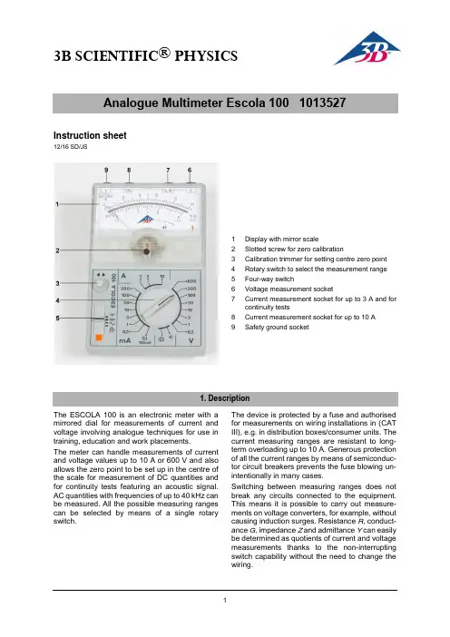
3B SCIENTIFIC ® PHYSICSInstruction sheet12/16 SD/JS1 Display with mirror scale2 Slotted screw for zero calibration3 Calibration trimmer for setting centre zero point4 Rotary switch to select the measurement range5 Four-way switch6 Voltage measurement socket7 Current measurement socket for up to 3 A and for continuity tests8Current measurement socket for up to 10 A 9Safety ground socketThe ESCOLA 100 is an electronic meter with a mirrored dial for measurements of current and voltage involving analogue techniques for use in training, education and work placements.The meter can handle measurements of current and voltage values up to 10 A or 600 V and also allows the zero point to be set up in the centre of the scale for measurement of DC quantities and for continuity tests featuring an acoustic signal. AC quantities with frequencies of up to 40 kHz can be measured. All the possible measuring ranges can be selected by means of a single rotary switch.The device is protected by a fuse and authorised for measurements on wiring installations in (CAT III), e.g. in distribution boxes/consumer units. The current measuring ranges are resistant to long-term overloading up to 10 A. Generous protection of all the current ranges by means of semiconduc-tor circuit breakers prevents the fuse blowing un-intentionally in many cases.Switching between measuring ranges does not break any circuits connected to the equipment. This means it is possible to carry out measure-ments on voltage converters, for example, without causing induction surges. Resistance R , conduct-ance G, impedance Z and admittance Y can easily be determined as quotients of current and voltage measurements thanks to the non-interrupting switch capability without the need to change the wiring.The analogue multimeter conforms to safety regu-lations for electrical measurement, control and la-boratory equipment, as specified in DIN EN 61010-1, protection class 2 and to measuring category CAT III for up to 600 V. The nominal voltage be-tween the phase conductors and the neutral for voltage and current measurements (in circuits di-rectly connected to mains electricity) must not ex-ceed 600 V in order to conform to CAT III.The meter is intended for measurements within its measuring ranges and in a measuring environ-ment as described in detail in the course of this manual. Safe operation of the multimeter is guar-anteed if it is solely used as specified. Safety can-not be guaranteed, however, if the multimeter is used incorrectly or handled without due care and attention. In order to avoid serious injury due to cur-rent or voltage shocks, the following safety instruc-tions are to be observed at all times.The multimeter may only be used by persons who are able to recognise the risks of contact and take due precautions to avoid them. Voltages in excess of 33 V AC (RMS) or 70 V DC are to be regarded as actively dangerous if the current, charge or en-ergy stored should exceed certain values (see DIN EN 61010-1).∙Carefully read the instruction manual before using the multimeter and obey the instruc-tions therein.∙The multimeter may only be used in a dry, dust-free environment with no risk of explo-sions occurring.The assumption needs to be made that unfore-seen voltages may be present in the vincinity of objects being measured (e.g. faulty equipment). ∙Before using the multimeter, check the hous-ing and measuring leads for damage and if there should be any malfunctions or visible damage, the multimeter is not to be used. Pay specific attention to the insulation for the measuring sockets.∙The multimeter may not be used to make measurement on circuits which exhibit corona discharge (high voltage).∙Particular care is to be taken when making measurements on high-frequency circuits where dangerous voltages may arise due to superimposition of components.∙The authorised measuring range is not to be exceeded. If measurements are made when the magnitude of the variable is unknown, al-ways select a large measuring range before shifting down to lower ones. ∙Make very sure that the voltage value be-tween the measured contact and earth or be-tween the ground socket and the measure-ment socket does not exceed 600 V.∙Before using the analogue multimeter to check that a voltage source is not exhibiting any actual voltage, check that the meter is working properly by selecting the battery test function.∙When measuring current, make sure the elec-tricity is turned off before the analogue multi-meter is connected into the circuit.∙When making measurements, always con-nect the ground lead first. Disconnect the sig-nal measurement lead before unplugging the ground.∙Turn off the multimeter before opening the casing, disconnect the power to the circuit and the measuring leads from the multimeter.∙If measurements are made where there are any risks of coming into contact with electric-ity, a second person is to be informed.∙When the multimeter is used by teenagers, trainees etc., a suitable person should super-vise to ensure the equipment is used safely. ∙If measurements are to be made where volt-ages exceed 33 V AC (RMS) or 70 V DC, be especially careful and only use safety experi-ment leads.Measuring categories according to DIN EN 61010-1.CAT I or unstipulated: Approved for measure-ments in circuits which are not directly connected to the low voltage mains grid (e.g. batteries). CAT II: Approved for measurements in circuits which are directly connected, by a mains lead and plug for instance, to the low voltage mains grid (e.g. household or office appliance and lab equip-ment).CAT III: Approved for measurements in circuits which ar e part of a building’s wiring installation (e.g. stationary consumers, distribution terminals, appliances connected directly to the distribution box).CAT IV: Approved for measurements in circuits which are directly connected to the source of the low voltage mains (e.g. electricity meters, main service feed, primary excess voltage protection).Display:Scales: 0 … 10, linear0 … 3, linearScale length: 80 mmPointer deflection: 0…90°Electricalzero-point offset: in all DC rangesMeasurements:Voltage ranges: 0.1/ 0.3/ 1/ 3/ 10/ 30/100/ 300/ 600 V AC/DC Current ranges: 0.1/ 0.3/ 1/ 3/ 10/ 30/100/ 300 mA AC/DC1/ 3/ 10 A AC/DCInput resistance: 1 MΩ AC/DCVoltage drop whenmeasuring current: 100 mV approx. AC/DCReference conditions:Ambient temperature: 23 °COperating alignment: Vertical/horizontalSignal form: Sine (1% max. discrep-ancy)Peak factor:Frequency range: 40 Hz … 50 Hz … 5 kHzAccuracy (at reference conditions):DC quantities: Class 2DC withzero-point offset: Class 5AC quantities: Class 3Extended frequency range (class 10):0,3 – 600 V: 40 Hz … 50 Hz … 40 kHz3 – 3000 mA: 40 Hz … 50 Hz … 40 kHz10 A: 40 Hz … 50 Hz … 40 kHz Resistance, conductance, impedance, admit-tanceThese quantities can be determined by forming various quotients involving “simultaneous meas-urements” of current and voltage.R = U / I: below 1 mΩ… above 10 MΩS = I / U: below 1 µS … above 30 SZ = U / I: below 1 mΩ… above 10 MΩ,40 Hz … 40 kHzY = I / U: below 1 µS … above 30 S,40 Hz … 40 kHz Overload protection:Voltage ranges: 600 V long-term in allvoltage rangesCurrent ranges: 10 A of long-term load-ing in 3-A and 10-ArangesElectrical safety:Safety specifications: EN 61010-1 Measuring category: CAT III: 600 V Contamination level: 2Protection type: IP20Connectors: 4-mm safety socketsProtection:Fuses: 2x FF 10 A/600 V(10 x 38 mm)Breaking capacity: 20 kA3B order number: 5008564Power supply:Battery: 1x 1.5 V, AA IEC LR6 Automatic cut-off after: 45 min ± 10 minElectromagnetic compatibility:Interference emission: EN 55011:2009 Interference resistance: EN 61326-1:2013Operating conditions:Ambient temperature: 5 °C ... 23 °C … 40°C Storage temperature: -20 … 70°CRelative humidity: <85% with no condensa-tionGeneral data:Shock test: max. 147 m/s² Dimensions: 100x150x50 mm3 ap-prox.Weight: 300 g approx.Use in vertical positionUse in horizontal positionCAT IIIEarth symbol∙Set up the ESCOLA 100 meter either horizon-tally or vertically.∙Do not connect measuring leads to begin with.∙ or .The needle will point to the zero point of the dial.If it does not, the amount of charge of the batteryshould be checked.6.1 To switch on:∙,6.2 Checking battery charge:∙Set the four-way switch to∙Disconnect all measuring leads.∙placed immediately.6.3 Zero point calibration:∙Set up the analogue multimeter either hori-zontally or vertically.∙Set the four-way switch to .∙Turn the rotary switch to 600 V.∙Connect the common/ground socket and thevoltage measurement socket together bymeans of a short connecting lead.∙Turn the zero-point trimmer screwto adjustthe zero point as needed.6.4Zero point calibration for centre zeropoint:For measurements of DC current and voltage, thezero point of the scale can be moved to the centreof the dial.∙Disconnect all measuring leads.∙rotary switch to a DC current or voltage range,∙Use the zero-point trimmer to line up the nee-dle precisely in the centre of the dial.6.5 To switch off:∙.6.6 If a measurement is interrupted by batterycut-out:After 45 minutes of use, the multimeter is auto-matically shut off and the needle will then point to.To switch back on:∙Set the four-way switch of the analogue multi-meter to off and then use it to turn the meterback on.∙If measurements are made when the magni-tude of the variable is unknown, always select a large measuring range before shifting down to lower ones.∙ Connect the terminal at the lower potential to the common/ground socket.∙Connect the common/ground lead first and only then the signal lead.7.1 DC currents up to 3 A:∙ Set the four-way switch to .∙Alternatively, if measurements are to be made ∙Select the required current measuring range to a range measured in mA or A.7.2 AC currents up to 3 A:∙∙Select the required current measuring range to a range measured in mA or A.∙ Set up a measuring range of 10 A.∙ Connect the terminal at the lower potential to the common/ground socket.∙Connect the common/ground lead first and only then the signal lead.8.1 DC currents up to 10 A:∙ Set the four-way switch to .∙Alternatively, if measurements are to be made8.2 AC currents up to 10 A:∙∙If measurements are made when the magni-tude of the variable is unknown, always selecta large measuring range before shifting downto lower ones.∙Connect the common/ground lead first and only then the signal lead.∙For measurements of voltage up to 100 mV, set the rotary switch to the range 0.1 mA/100 mV.9.1 DC voltages up to 600 V:∙Set the four-way switch to .∙Alternatively, if measurements are to be made∙Select the required measuring range to a range measured in V.9.2 AC voltages up to 600 V:∙∙Select the required measuring range to a range measured in V.∙Connect up the component to be tested.∙Set the four-way switch to and turn the rotary switch to . If there is continuity of cur-rent (R< 1 kΩ), an audible signal will sound.11.1 DC voltages and currents:∙Set the four-way switch to .∙Use the rotary switch to set the desired volt-age measuring range and read off the meas-urement.∙Set a suitable current measuring range and read off the measurement.11.2 AC voltages and currents:∙∙Use the rotary switch to set the desired volt-age measuring range and read off the meas-urement.∙Set a suitable current measuring range and read off the measurement.The battery and the two fuses are located under-neath the back cover of the meter.One fuse each is provided for the 3 A and 10 A sockets:FF10 A/600 V, breaking capacity: at least 10 kA (3B order number: 5008564)The polarity is indicated by plus and minus signs inside the fuse holder compartment. A mechanical system ensures the battery makes no contact if it is inserted the wrong way round.12.1 Battery testing:Batteries which are discharged and have not been used for a while may leak.12.2 Changing the battery:∙ Unscrew the back of the casing.∙ Replace flat batteries with 1.5-V alkaline bat-teries of size AA IEC LR6.∙ Place the negative pole of the battery on the spring.∙Close the casing again.12.3 Changing fuses:∙ Unscrew the back of the casing. ∙ Check the fuses.∙ Blown fuses should be replaced with ones of the same rating.∙Close the casing again.∙For cleaning, use a soft cloth, slightly mois-tened with alcohol, or a brush.Electrostatic charging of the display window can affect the measurements under certain circum-stances:∙ To remove such charge, use a soft clothslightly soaked in alcohol or a paint brush. Dirt or moisture in the measurement sockets can affect readings.∙ Shake out any dirt that may be in the meas-urement sockets.∙ Soak a new swab with isopropyl alcohol andwork around the inside of each measurement socket. ∙ The packaging should be disposed of at local recycling points.∙Should you need to dis-pose of the equipment itself, never throw it away in normal domes-tic waste. If being used in private households itcan be disposed of atthe local public waste disposal authority.∙Comply with the applicable regulations for the disposal of electrical equipment.∙Do not dispose of the batteries in the regular household garbage. Follow the applicable le-gal regulations (UK: Waste Batteries and Ac-cumulators Regulations, EU: 2006/66/EC).。
⾦⼠顿DataTraveler100G316G的U盘量产过程⼏年前买的⾦⼠顿16GU盘由于这⼏天安装系统做成了启动盘,刚开始还可以正常,谁知道睡了⼀觉就废了。
第⼀次尝试修复具体表现: 1、插上电脑可以识别盘符,但是打不开,提⽰请插⼊U盘。
2、磁盘管理中可以显⽰盘符,但提⽰“⽆媒体” 既然有现象咱就尝试修复呗,于是⼀阵度娘,还别说真找到了⼀堆量产教程。
接下来就不细说了,⼀个⼀个尝试修复,结果都以失败告终。
现象就是报红(Drive :Size_Err)怎么都过不去,主要尝试STOOL的各种版本,此时已经过去了好⼏天有点⼼⼒憔悴:⼏块钱的东西折腾它⼲嘛,坏就坏了,再买⼀个吧,于是乎扔到⼀遍不管了。
过程中也看到有⼈说这个u盘保质5年,可以申请售后,我这个⼀来没有发票,⼆是可能也过保了,⼏块钱的东西还不够邮费,算了。
贴⼀下具体型号 设备描述: [E:]USB ⼤容量存储设备(Kingston DataTraveler 3.0) 设备类型: ⼤容量存储设备 协议版本: USB 2.10 <- 提醒:该设备⽀持USB3.0规范,将其连接到USB3.0接⼝可提⾼其性能 当前速度: ⾼速(HighSpeed) 电⼒消耗: 300mAUSB设备ID: VID = 0951 PID = 1666设备供应商: Kingston 设备名称: DataTraveler 3.0设备修订版: 0100产品制造商: Kingston 产品型号: DataTraveler 3.0产品修订版: PMAP 主控⼚商: Phison(群联) 主控型号: PS2251-07(PS2307) - F/W 01.03.10 [2013-12-20]闪存识别码: ADDE94DA74C4 - Hynix(海⼒⼠) H27UCG8T2ATR [MLC-8K]再次尝试 过了⼏天,新买的u盘也⽤上了,还是⾦⼠顿⼀样的型号,64G⼤⼩,看来对这个牌⼦⼼⾥还是⽐较认可,竟然可以⽤好⼏年~这时⼜想到曾经陪伴我好⼏年的⼩强⼫体了,这么容易就坏了不应该啊?是不是⽅法不对?再量产⼀下应该可以吧?反正都坏了,再试试吧。

联想魔盘B100使用说明书使用产品前请仔细阅读本使用说明书V1.0本使用说明书版权所有©2003 联想北京有限公司目录1 产品介绍2 产品规格性能参数3 系统要求4 安装手册Win98/SE操作系统WinMe/2000/XP操作系统5 产品使用说明6 工具软件使用说明附录技术规范一产品介绍联想魔盘是一种采用Flash芯片为存储介质通过USB接口与计算机交换数据的新一代可移动存储盘和传统的存储盘不一样的是联想魔盘存储容量大体积小重量轻数据保存期长而且安全联想魔盘是一种无驱动器即插即用的电子存储盘便于携带耐高低温抗震性能强防磁防潮是移动办公及文件交换的理想存储产品二产品规格性能参数接口方式 Universal Serial Bus 1.0/1.1 (USB 1.0/1.1)供电电源由USB接口直接供电不需外接电源传输速率写入600KB/秒读出800KB/秒实际速率与计算机配置有关操作系统 Windows 98/SE Windows Me Windows 2000 Windows XP Mac ®OS 8.6 及以上版本Linux 2.4.0 及以上版本容量 16MB 32MB 64MB 128MB 256MB 512MB 实际容量以产品具体型号为准指示灯指示灯亮表示已经连接并处于等待读写状态指示灯闪烁表示正在进行读写数据指示灯灭表示计算机处于休眠状态可以安全从系统中拔出尺寸长宽高 81mm 23mm 12.5mm重量 40g启动功能在主板支持USB-ZIP或USB-HDD情况下有启动功能加密功能: 在Windows操作系统中可使用自带加密软件对其中的数据进行密码保护使用寿命可擦写10万次以上读出操作不影响寿命驱动程序仅在Windows 98/SE 系统下需要安装驱动程序三系统要求硬件系统要求带USB接口的PC机苹果机及笔记本电脑操作系统要求Windows 98/SE Windows Me Windows 2000 Windows XP Mac ®OS 8.6及以上版本Linux 2.4.0 及以上版本四安装手册4.1 Windows 98/SE操作系统4.1.1 确认计算机具有USB接口4.1.2 确认计算机的USB控制器工作是否正常检测的方法是打开"控制面板" > "系统" >"设备管理器" 检查是否存在"通用串行总线控制器"一项如果存在请检查是否已正常工作如果工作不正常请检查计算机BIOS中的USB选项是否打开或系统配置是否正确通过以上两个步骤的检查后就可以进行联想魔盘的安装4.1.3 把" 联想魔盘驱动光盘"放入计算机的光驱中,运行驱动光盘Win98目录中的可执行文件setup.exe4.1.4 把联想魔盘插到计算机的USB的接口系统就会进行硬件查找按照系统指示进行安装安装完毕后在我的电脑里会出现一个可移动磁盘如图1所示这时就可以象操作其它硬盘一样操作此联想魔盘如果第一次工作不正常请重新启动一次您的计算机注意如果操作系统找不到驱动程序请选择指定目录驱动程序文件存在于光盘根目录下的Win98\Drivers目录中图14.2 Windows Me/2000/XP操作系统4.2.1 确认计算机具有USB接口4.2.2 确认计算机的USB控制器工作是否正常检测的方法是打开"控制面板"->"系统" >"硬件" >"设备管理器" 检查是否存在"通用串行总线控制器"一项如果存在请检查是否已正常工作如果工作不正常请检查计算机BIOS中的USB选项是否打开或系统配置是否正确4.2.3 经过以上步骤确认后接下来的工作只是简单地把联想魔盘插入到计算机的USB接口即可系统会自动识别联想魔盘并在"我的电脑"中出现可移动磁盘盘符注意如果联想魔盘使用U-Storage工具重新分割为两个磁盘分区在Windows 2000下可能无法显示两个盘符请更新系统到Windows 2000 Service Pack 3或以上版本五产品使用说明5 1 将联想魔盘插入计算机的USB接口时指示灯变亮表示已经连接处于等待读写状态5 2 当对联想魔盘进行任何操作如写文件修改文件删除文件的过程中LED指示灯会闪烁当读写数据完成时LED指示灯会停止闪烁注意不要在联想魔盘的LED 指示灯闪烁时拔下联想魔盘这样可能导致您的数据被毁坏或使FAT表破坏而出现蓝屏如不慎在LED指示灯闪烁时拔出致使联想魔盘不能正常工作重新格式化后联想魔盘即可正常工作硬件不会被损坏5 3 在Windows 98/SE操作系统中只要联想魔盘的LED指示灯熄灭就可从USB接口中将联想魔盘拔出可移动磁盘的盘符会自动消失在Windows Me/2000/XP操作系统中联想魔盘从USB口拔出前应先通过系统右下角状态栏中的拔下或弹出硬件图标(如图2所示)停用该USB设备待系统提示该设备已安全移除时再拔出如系统提示现在无法停止该设备请稍候再停止该设备请确认与联想魔盘有关的应用程序均已关闭然后再安全停用此设备图2如不停用该USB设备而直接拔出联想魔盘系统会有如图3的错误提示不同操作系统的错误提示画面不完全相同图例为Windows 2000系统下的提示信息图3六工具软件使用说明6.1 软件安装U-Storage支持Windows 98SE/ME/2000/XP如果在Windows 2000/XP下安装你必须具有系统管理员权限U-Storage安装程序位于联想魔盘驱动光盘的Tools目录下请双击[U-Storage.exe] 并按照屏幕说明方式安装注意1. 当安装应用程序时请将联想魔盘插入计算机USB接口2. 如果你没有将联想魔盘插入计算机USB接口在Windows XP下需再次安装U-Storage程序3. 在Windows 98SE/ME下安装完应用程序后需重新拔插联想魔盘6.2 软件卸载请点击Windows [开始] 菜单选择[U-Storage]下的[Uninstall U-Storage]或者点击Windows [开始] 菜单选择[设置], [控制面板] ,[添加/删除程序]找到[U-Storage 2.5],选择[更改/删除]6.3 第一次使用 U-Storage程序:注意U-Storage程序仅针对一个联想魔盘如果你不使用“重新分割”, “变更密码”, 或“登入” 等功能时可以同时插入多个设备如果需使用时请只保留一个设备否则可能会有数据丢失或操作失败的情况发生安装完成后可在计算机的任务栏上发现U-Storage的图标如图4或图5所示图76.4.2 选择你所需的分割类型6.4.3如果选择壹个磁盘驱动器开启保密功能显示画面如图8所示你可移动图上的箭头调整所需的“公共资料区” 与“保密资料区”大小或直接写入所需的值但需注意的是“保密资料区” 的最小容量为1MB你可在“新密码”窗口中设定密码最多可写入8个字符你可在密码提示窗口中键入你的密码提示最多可写入32个字符在下次登录保密区时点击提示会出现你所设定的密码提示图8注意本说明书出现的图片为示意图图中涉及的容量信息请以实际产品为准6.4.4单击[确定]出现确认对话框如图9所示请确定所有数据已备份完全图96.4.5如果选择“两个磁盘驱动器开启保密功能”, 显示画面如图10所示, 你可移动图上的箭头调整所需的区域大小或直接写入所需的值但需注意的是“保密资料区” 的最小容量为1MB当你设定位于下方的“公共资料区”完成后,位于上方的“公共资料区” 与“保密资料区”的容量值将会自动调整. 你也可直接写入所需的值. 你可在“新密码”窗口中设定密码最多可写入8个字符你可在密码提示窗口中键入你的密码提示最多可写入32个字符在下次登录保密区时点击提示会出现你所设定的密码提示图106.4.6单击[确定]并确定所有数据已备份完全当扇区分割完成后出现提示对话框如图11所示图116.4.7当完成“重新分割”后U-Storage的安装程序“Setup.exe”会自动备份到“公共区”你可以在其他计算机上执行此程序安装U-Storage工具6.5 登入保密区:如果磁盘设置了保密功能则需要键入密码后方可进入保密区6.5.1双击U-Storage 在任务栏的图标或点击[登录] 键, 出现画面如图12所示图12注意当你在进行登入及注销操作时,请确定磁盘上没有正在执行的程序或打开的文件仍未关闭因为这将会造成数据流失6.5.2在“密码”窗口中键入密码Ø 你可在“重新分割” 或“更改密码” 中建立密码提示当你忘记密码时可以点击“提示” 键取得提示, 但密码提示只会出现3秒如图13所示图13Ø 如果你键入密码错误三次则会弹出提示对话框如图14所示图14Ø 当你在进行登入及注销操作时,请确定磁盘上没有正在执行的程序或打开的文件仍未关闭否则将会出现提示对话框如图15所示在Windows 2000下在登入及注销前必须先将资源管理器窗口关闭否则也会出现此对话框图156.5.3 点击“确定”6.5.4当资源管理器窗口为“保密区” 时您可对其进行读写操作为区别起见保密区的背景将以不同的颜色显示出来如图16所示图166.6 注销保密区:6.6.1在资源管理器窗口下双击U-Storage 或点击[注销] 键注意当你在进行登入及注销操作时,请确定磁盘上没有正在执行的程序或打开的文件仍未关闭因为这将会造成数据流失Ø 当你在进行登入及注销操作时,请确定磁盘上没有正在执行的程序或打开的文件仍未关闭否则将出现对话框如图17所示图176.6.2当资源管理器窗口显示“公共区”时,可对此区进行读写操作6.7 更改密码:更改密码选项可让使用者更改密码及键入密码提示仅可对“保密区”做此设定6.7.1点击更改密码按键显示画面如图18所示图186.7.2键入正确的密码在“目前密码”6.7.3键入新密码并确认密码.密码最多可键入8个字符6.7.4你可在密码提示栏上键入提示6.7.5 点击“确定”6.8 制作启动盘制作步骤及注意事项1) 制作启动盘功能仅针对Windows 98 SE/ME/XP在Windows 2000下不支持此功能2) 在制作过程中请先将杀毒软件暂时关闭3) 确定Windows 系统安装在C 盘4) 每次仅对一个设备进行制作5) 如果要制作为USB HDD的开机方式不可将设备设置为“保密区”制作USB HDD功能仅支持Windows 98 SE注意如果你在保密区状态下制作启动盘,计算机会自动注销到公共区您在此之前写入设备的资料将会遗失请按照下述的方式进行制作Windows XP 的制作过程与Windows 98 SE/ME是不同的且启动制作功能在Windows 2000下并不适用Windows 98 SE/ME:1). 在U-Storage 的画页下点选[工具] 键出现画面如图19所示图192). 你可以选择所需的启动功能USB ZIP 或USB HDD USB HDD只能在Windows98 SE下执行Ø 如选择“USB HDD”则启动成功后位于.Ø 如果产品具有保密功能的只有USB ZIP 功能可执行3). 点击“确定” 键出现提示对话框如图20所示注意制作启动盘将格式化磁盘的公共区, 请特别注意图204). 点击确定后完成启动制作Windows XP:1). 先插入3.5’’的软盘在资源管理器或我的电脑中用鼠标右键点选软盘并选择”格式化”功能2). 在格式化设置对话框中选择制作启动盘功能选项制作启动软盘3). 在U-Storage 中点击[工具] 选择USB ZIP然后点击确定4). 制作完成出错提示图21如果出现如图21的提示表示Windows系统未完成制作启动盘(在Windows 98 SE/ME下请确认是否有\WINDOWS\COMMAND\EBD目录在Windows XP下确认启动软盘正确插入软驱)图22如果出现如图22的提示请检查是否磁盘空间不足注意1. 当完成使用魔盘启动后如果选择USB HDD 显示出为C: 磁盘驱动器选择USBZIP 显示出A: 磁盘驱动器2. 当完成使用魔盘启动后请勿任意删除磁盘中之启动文件否则可能会造成下次无法启动3. 因各厂商BIOS设计均不同无法保证所有的计算机均能使用启动盘启动6.9 磁盘重整如果产品容量已受损请使用此功能,磁盘重整功能会尝试修复你的磁盘6.9.1点击Windows [开始] 菜单选择[U-Storage]下的[Recover Disk]出现画面如图23所示图236.9.2磁盘重整需要一段时间来操作如16MB容量的产品约需1.5分钟6.9.3点击[开始] 键后开始进行磁盘重整.注意磁盘重整时会将所有数据格式化请先备份你的数据注意事项1 本产品附送应用软件UTA Professional的使用方法请参照用户光盘中提供的readme文件2 U-Storage软件的重新分割功能将会删除魔盘上附带的应用软件UTA Professional 重新分割后如果需要使用UTA Professional 可以使用用户光盘重新安装附录技术规范条目说明硬件带USB接口的IBM PC及兼容机笔记本计算机等操作系统Windows 98/SE Windows Me Windows 2000 Windows XP驱动程序仅在Windows 98/SE 系统下需要安装驱动程序电源USB总线供电 4.5V~5.5V容量** 16MB/32MB/64MB/128MB/256MB/512MB主机接口Universal Serial Bus 1.0/1.1 (USB 1.0/1.1)工作电流* < 50mA等待状态电流* < 300 ALED指示灯指示灯亮表示已经连接处于等待读写状态指示灯闪烁表示正在进行读写数据指示灯灭表示可以安全从系统中拔出数据读取速度* 800KB/秒与计算机配置有关数据写入速度* 600KB/秒与计算机配置有关工作环境温度* -40 ~ +70存放温度* -50 ~ +85运行相对湿度* 5% ~ 95%存放相对湿度* 1% ~ 98%EMI标准UL FCC (B类) CE* 这是理论数值仅供参考** 由于闪存芯片特性及文件格式管理需要实际可用存储容量可能会略少于理论数值实际容量以产品具体型号为准。
433对拷方法【最新版】目录1.对拷方法的定义与概述2.对拷方法的应用场景3.对拷方法的具体操作步骤4.对拷方法的优缺点分析5.对拷方法的未来发展趋势正文【1.对拷方法的定义与概述】对拷方法,是一种在计算机领域常用于比较两个文件内容是否相同的技术手段。
该方法通过将两个文件进行二进制比较,以判断它们之间的差异。
对拷方法被广泛应用于软件开发、数据同步、信息安全等领域,以确保数据的一致性和完整性。
【2.对拷方法的应用场景】对拷方法在许多场景下都有应用,例如:- 软件开发:在开发过程中,对拷方法可以用于比较代码库中的不同版本,以追踪和合并修改。
- 数据同步:对拷方法可用于比较两份数据,以便找出它们之间的差异并进行同步。
- 信息安全:对拷方法可用于比较两个文件,以确定它们是否被篡改过。
【3.对拷方法的具体操作步骤】对拷方法的具体操作步骤如下:- 首先,读取两个文件的内容,将它们转换为二进制形式。
- 然后,逐位比较两个二进制文件,以找出它们之间的差异。
- 最后,根据比较结果,生成一份包含差异的报告。
【4.对拷方法的优缺点分析】对拷方法的优点包括:- 高效:对拷方法可以直接比较二进制数据,因此速度较快。
- 精确:对拷方法可以找出两个文件中的任何差异,无论是大小的改变还是内容的改变。
对拷方法的缺点包括:- 不适用于所有文件类型:对拷方法仅适用于文本文件或二进制文件,不适用于其他类型的文件。
- 无法处理格式差异:对拷方法无法处理两个文件之间的格式差异,例如,一个文件可能是另一个文件的加密版本。
【5.对拷方法的未来发展趋势】随着计算机技术的不断发展,对拷方法也在不断改进。
未来的发展趋势包括:- 更高效的算法:研究人员正在寻找更有效的算法,以提高对拷方法的速度和准确性。
silagra100的中文说明书silagra100是一款能够实现生物识别的医疗设备,为生物识别技术领域提供了新的研究方向——生物识别中不同阶段的应用。
该设备具有高度自动化,可以识别所有类型的生物,并且在实验室环境中工作的效率是目前最好的生物识别设备之一。
该设备还具有强大的数据收集功能,能够通过分析和对比生物信息以识别出该生物,该数据是用于生物信息的分析和评价方法的关键,并且提供了可以帮助人们了解所使用的生物。
该设备能够同时收集生物信息与生物特征数据、身份信息与结构信息,并可以帮助人们了解生物识别领域中各种不同阶段的应用。
1、设备的主要功能使用该设备进行实验时,不需要在外部环境中使用实验室设备进行验证。
设备能够进行多种类型的生物识别以及身份识别。
可提供的主要功能包括:身份信息采集、对比与区分,以及身份验证服务。
2、生物特征数据Silagra100可以同时收集用户的生物特征数据,包括生物特征数据。
用户可以将生物特征数据应用于各种不同研究领域。
用户可以通过Silagra100收集用户使用时产生的数据,包括用户指纹数据、面部特征、耳廓特征、面部轮廓数据、面部表情数据、身体比例数据、面部肌肉数据、呼吸频率数据、运动参数数据、血氧数据、血液与尿液数据、血液样本信息、体温数据、瞳孔信息、呼吸参数、声音、运动参数、面部特征数据、身体比例数据以及身体结构数据等。
3、身份信息与结构信息silagra100是一款可靠的工具来收集和分析生物信息,在身份信息与结构信息这两个部分中都能获得很好的结果。
身份信息是用来确定身份和位置的重要特征。
身份信息中包括一个或多个可确认身份的信息,如患者名称、年龄、性别、身高、体重等。
一个人的身份信息包含了一个特定器官在他出生时所包含的信息。
结构信息则可以表示人们是如何活动的,也就是他们是如何产生各种生理变化、进行器官互换、或运动模式是否有变化等。
这些数据能够帮助人们更好地了解器官移动和运动的原因、以及器官位置变动给身体带来的影响和需要采取的措施。
VICTORY V100 User Guide• Do not use this amplifier near water or any other liquid• Do not block an y openings• Do not attempt to clean the amplifier with any fluids: use only a dry clothDo not attempt to modify or service this product yourselfRemoving covers could mean you are exposed to dangerous voltages that may result in severe injury or deathRefer all servicing to qualified service personnel• Damage Requiring Service: Unplug this product from the wall outlet and refer servicing to qualified service personnel under the following conditions:(a) When the power-supply cord or plug is damaged;(b) If liquid has been spilled, or objects have fallen into the product;(c) If the product has been exposed to rain or water;(d) If the product does not operate normally by following the operating instructions. Adjust only those controls that are covered by the operating instructions. Improper adjustment of other controls may result in damage and will often require extensive work by a qualified technician to restore the product to its normal operation;(e) If the product has been dropped or damaged in any way;(f) When the product exhibits a distinct change in performance - this indicates a need for service. Replacement Parts: When replacement parts are required, be sure the service technician uses replacement parts specified by the manufacturer or have the same characteristics as the original part. Unauthorized substitutions may result in fire, electric shock, or other hazards.InputPlug your guitar in here!Channel switchThe V100 has two channels that you can switch between using this front-panel toggle, or a remote footswitch plugged into the Channel/Boost footswitch socket.Clean channelThe clean channel is indicated by a green LED channel indicator next to the gain control.Clean GainThis adjusts the input sensitivity. Use low settings for maximum clean headroom and higher settings when you want to introduce more natural valve overdrive to your tone.Balancing your input gain level with your master volume level is crucial in delivering the tone and feel that works best for you.Clean TrebleControls the high frequency content of your sound in the clean channel and is also a powerful tone shaper when it comes to overdrive character.Clean MiddleControls the midrange frequencies in your sound in the clean channel. Run the middle control higher to help cut through a band mix, or generally fatten and ‘widen’ your sound. Run it lower for a lighter, less -your-face’ kind of sound.Clean BassControls the low frequency content of your sound in the clean channel. Higher levels of bass can be goodControls the low frequency content of your sound in the overdrive channel. It’s well worth experimenting with getting your preferred settings of bass and resonance together: they both affect low-end response in different ways.Overdrive MiddleControls the midrange frequencies in your sound in the overdrive channel. Mid frequencies are a crucial, defining factor with overdriven tones so spend some time getting to understand how this control interacts with the bass and treble pots for your optimum EQ balance.Overdrive TrebleControls the high frequency content of your sound in the clean channel and is also a powerful tone shaper when it comes to overdrive character.Overdrive VolumeEach channel has its own volume control, as well as the extra dual master volumes. Use this one to balance the volume level of the overdrive channel to taste when switching between channels and modes.Overdrive ReverbThe V100 features independent reverb controls for each channel. Adjust to taste for the overdrive channel. The reverb is also footswitchable on/off.Master control section – these 4 controls are not channel dependent.Master 1 & 2switch to ON. To extend valve life, the amplifier can be switched to ‘Standby’ when not being played. REAR PANELVoltage selectorSelects the correct mains voltage for your territory. Please refer to a qualified technician before even thinking about moving this switch. If you do find yourself in foreign climes where the mains voltage is different to home, (and the water tastes funny), it will be necessary to switch this selector. The mains fuse must always be changed at the same time. Failure to do this will result in either the mains fuse blowing as soon as the amp is turned on or the amp running with a fuse that is of too higher value to provide adequate safety protection. Generally, the fuse value will double if the mains voltage is halved, (i.e. if it’s a 2A f use in the UK @ 230V, it will needs to be a 4A fuse for the USA @ 115V).Always use the correct rating and type of fuse. Victory amplifiers exclusively use UL-approved 20x5mm ‘T’ or ‘Timed’ fuses. If you have difficulty acquiring the correct fuses, please contact Victory using ************************.uk.Mains inlet, (IEC Socket)Please only use the correct mains cord for your territory!PLEASE NOTE: The lightning flash with arrowhead symbol, within an equilateral triangle, is intended to alert the user to the presence of uninsulated ‘dangerous voltage’ within the product’s enclosure that may be of sufficient magnitude to constitute a risk of electric shock. Terminals labelled as “Speaker Outputs” must be connected to a speaker cabinet of the designated load rating using an un-shielded two conductor cable for speaker use at all times during operation. Never use a guitar cable to connect the amplifier to a speaker as thi s presents the amplifier with a ‘capacitive load’. This can cause instability or oscillation which may seriously damage valves and/or the expensive output transformer.The output transformer in the V100 has 3 separate secondary windings; a 4 Ohm, an 8 Ohm and a 16 Ohm. This makes it easy to connect many different combinations of speakers. There are five speaker output jacks: 2 x 4 ohms, (wired in parallel), 2 x 8 ohms, (wired in parallel) and 1 x 16 ohms.So here are all the possible combinations:For a single 4 Ohm cabinet, use either of the 4 Ohm sockets.For a single 8 Ohm cabinet, use either of the 8 Ohm sockets.For a single 16 Ohm cabinet, use the 16 Ohm socket.For a pair of 8 Ohm cabinets, use both of the 4 Ohm socketsFor a pair of 16 Ohm cabinets, use both of the 8 Ohm sockets.OUTPUT VALVE FUSES and LED’sThe two panel mounted fuse holders protect each pair of output valves as labelled.will switch over when the Channel is switched. With Auto Assign ‘ON’, LOOP 1 is for Channel 1 and LOOP 2 is for Channel 2.This is so you can have a different bank of effects for each channel.However, if Auto Assign is switched ‘OFF’ then use the dual footswitch provided to change from FX loop 1 to FX loop 2. Please note, in the Auto Assign OFF mode, one of the FX loops will always be on & all the footswitch is able to do is toggle between Loop 1 & 2. To create a situation where you can turn off the FX loop, we suggest only using FX in loop 1 & leaving FX loop 2 empty. This way, by toggling between FX loop 1 & 2 you essentially are switching FX loop 1 on & off.External switching jacks, (Footswitch sockets)Effect Loop 1/2:Connect a 2 way latching footswitch here to select Loops 1 and 2Channel / Boost:Connect 2 way latching footswitch here to change Channels and engage/disengage the overdrive channel Boost function.Master Volume / Reverb: Connect a 2 way latching footswitch here to select between Master 1 and Master 2, and also turn the Reverb on and off.Amplifier Dimensions:SIZE (mm): 660(w) x 260(h) x 260(d) Unboxed 760(w) x 360(h) x 360(d) BoxedWeight: 25,7Kgs Unboxed 27.7Kgs BoxedWarrantyAll Victory products come with a 5 year limited warranty. This covers any defects in manufacturing or faulty components. Valves and speakers are warrantied for 90 days from the purchase date but replacement parts will be at our discretion. Please contact your local dealer if you have any issues with your Victory product.A note from Team VictoryWe’ve built your Victory Amplifier as a professional, no-compromise musical instrument, with a great deal of pride and an absolute commitment to tone. We encourage you to learn to get to know it by experimenting with all the controls, in order to discover its vast array of tonal combinations.Thank you for making your tones with us: we wish you many years of achieving inspiring sounds to push your playing ever onwards.。
PC100USB Volume ControllerThe lightning flash with arrowhead sym-bol, within an equilateral triangle, is in-tended to alert the user to the presenceof uninsulated “dangerous voltage” withinthe product’s enclosure that may be ofsufficient magnitude to constitute a riskof electric shock to persons.The exclamation point within an equilater-al triangle is intended to alert the user tothe presence of important operating andmaintenance (servicing) instructions in theliterature accompanying the appliance.“WARNING”“TO REDUCE THE RISK OF FIRE OR ELECTRICSHOCK, DO NOT EXPOSE THIS APPLIANCE TORAIN OR MOISTURE.”1) Read these instructions.2) Keep these instructions.3) Heed all warnings.4) Follow all instructions.5) Do not use this apparatus near water.6) Clean only with dry cloth.7) Do not block any ventilation openings.Install in accordance with the manufacturer'sinstructions.8) Do not install near any heat sources such asradiators, heat registers, stoves, or other appa-ratus (including amplifiers) that produce heat.9) Do not defeat the safety purpose of the polar-ized or grounding-type plug. A polarized plughas two blades with one wider than the other. Agrounding type plug has two blades and a thirdgrounding prong. The wide blade or the thirdprong are provided for your safety. If the pro-vided plug does not fit into your outlet, consultan electrician for replacement of the obsoleteoutlet.10) Protect the power cord from being walked onor pinched particularly at plugs, conveniencereceptacles, and the point where they exit fromthe apparatus.11) Only use attachments/accessories specified bythe manufacturer.12) Use only with the cart, stand, tripod, bracket,or table specified by the manufacturer, or soldwith the apparatus. When a cart is used, usecaution when moving the cart/apparatus com-bination to avoid injury from tip-over.13) Unplug this apparatus during lightning stormsor when unused for long periods of time.14) Refer all servicing to qualified service person-nel. Servicing is required when the apparatushas been damaged in any way, such as power-supply cord or plug is damaged, liquid hasbeen spilled or objects have fallen into the ap-paratus, the apparatus has been exposed torain or moisture, does not operate normally, orhas been dropped.15) Excessive sound pressure from earphones andheadphones can cause hearing loss.Safety instructions<Caution>:Turning the volume setting too highis strongly discouraged. Not only is it potentially harmful to your ears, it may blow out the speak-ers.The following are supplied with the PC100USB.• USB cable x 1• Rubber feet x 4• Owner’s manual (this manual)The following are supplied with the PC100USB.• USB cable x 1• RCA plug cable x 2• Owner’s manual (this manual)After purchasing the PC100USB, check all acces-sories are included in the package.The PC100USB runs on USB bus power, so you can use it simply by connecting it to a computer with a supplied USB cable.Safety instructions ...................E-2Table of contents ....................E-3Introduction .........................E-3Overview ...........................E-3Supplied accessories ................E-3About power supply .................E-3FCC (U.S.A.) & ICES-003 (Canada)Information . . . . . . . . . . . . . . . . . . . . . . . . . E-3Names and functionsTop panel ........................E-4Rear panel .........................E-4Connection example .................E-5Computer requirements ..............E-5Computer settingsOutput device settingMac OS .........................E-6 Windows Vista/Windows 7 ..........E-6 Windows XP .....................E-6 Detail settingsMac OS .........................E-7 Windows Vista/Windows 7 ..........E-7 Windows XP .....................E-7 Computer sound volume .............E-7Specifications .......................E-7Declaration of EC Directive ...........E-8Fostex distributors list in Europe ......E-8Thank you very much for purchasing the Fostex PC100USB.To ensure the best performance, read this manual thoroughly before using the unit. Keep this manual handy for future reference.The Fostex PC100USB is a volume controller that allows you to control the audio volume at your hand when you monitor the computer audio output through a pair of powered monitor speakers such as the Fostex PM0.4n (or an audio system) or head-phones.The PC100USB receives a digital audio signal from a USB-connected computer and converts it to an analog signal. The converted signal is then volume-controlled and fed from the analog line output con-nectors as well as the headphones output connector.1. IMPORTANT NOTICEThis product, when installed as indicated in the instructions contained in this manual, meets FCC and ICES-003 requirements. Changes or modifications not expressly approved by Fostex Company for compliance could void the user’s authority to operate the equipment. DO NOT MODIFY THIS PRODUCT.2. IMPORTANTIn order to comply with FCC and ICES-003 requirements, use high quality shielded cables for connection to accessories and / or another products. If any cables are supplied with this product, they MUST be used. Follow all installation instructions. Failure to do so could void your FCC / ICES-003 authorization to use this product in the USA / Canada.3. NOTEThis equipment has been tested and found to comply with the limits for a Class B digital device, pursuant to Part 15 of the FCC Rules. These limits are designed to provide reasonable protection against harmful interference in a residential installation. This equipment generates, uses and can radiate radio frequency energy and, if not installed and used in accordance with instructions, may cause harmful interference to radio communications.Top panel❶ [LINK] indicatorIt lights in green when the unit is connected to a computer with a USB cable and the computer rec-ognizes the unit.❷[VOLUME] controlAdjusts the output level of both the [PHONES] and [OUTPUT] connectors.Rear panel❸[PHONES] connector (stereo mini jack) Connects stereo headphones.❹[OUTPUT] (L and R) connectors(RCA jacks)These connectors output analog audio signals. They are used to connect to a pair of powered monitor speakers such as the Fostex PM0.4n (or an audio system).When the [PHONES] jack is plugged in, no signal is output from the [OUTPUT] (L, R) jacks.❺[USB] connectorConnects to a computer using a supplied USB cable. Via USB, the PC100USB not only receives a digital audio signal but also gets power (USB bus power) from a computer.After USB connection is made, the computer rec-ognizes the PC100USB and automatically adds it to the list of sound output devices.<Note>:To get stable power supply, connect a USB cable directly to a USB port of your com-puter, without using a USB hub.4. Compliance with Part 15 of FCC Rules and Canadian ICES-003.This device complies with Part 15 of the FCC Rules. Operation is subject to the following two conditions: (1) This device may not cause harmful interference, and (2) this device must accept any interference received, including interference that many cause undesired operation.This Class B digital apparatus complies with Canadian ICES-003.Cet appareil numérique de la classe B est conforme à la norme NMB-003 du Canada.However, there is no guarantee that interference will not occur in a particular installation. If this equipment does cause harmful interference to radio or television reception, which can be determined by turning the equipment off and on, the user is encouraged to correct the interference by one or more of thefollowing measures:- Reorient or relocate the receiving antenna.- Increase the separation between the equipment and receiver.- Connect the equipment into an outlet different from that to which the receiver is connected.- Consult the dealer or an experienced radio/TV technician for help.<Caution>:Before you connect the PC100USBto a computer or audio equipment, turn downthe output volume of the audio equipment andthe PC100USB.<Memo>:When the [PHONES] jack is pluggedin, no signal is output from the [OUTPUT] (L, R)jacks.Computer requirementsYou can connect a computer that meets the following requirements.• A USB 2.0 port is provided.• OS: Windows XP, Windows Vista, Windows 7, Mac OS XOutput device settingTo receive a digital audio signal from your computer via USB, you must make audio output setting of the computer appropriately.The following describes how to select the PC100USB as the sound output device of a com-puter for each OS.• Mac OS1) Select “System preferences” from the Appledrop-down menu.2) Select “Sound” to open the “Sound” window and select “Output” tab at the top of thewindow.3) Select “USB Audio DAC” in the list box.• Windows Vista/Windows 71) Select “Hardware and Sound” from the Control panel.2) Select “Sound” to open the “Sound” window.3) Select “Playback” tab.4) Select “USB Audio DAC” and click the “Set De-fault” button, followed by the “OK” button.• Windows XP1) Select “Sound and Audio Device Properties” from the Control panel.2) Select “Audio” tab in the “Sound and Audio De-vice Properties” window.3) Select “USB Audio DAC” as the default devicefor playback and click the “OK” button.SpecificationsConnectors• [USB] connector• Connector type: USB Type B• Sampling frequency (Hz)/Bit rate: 32k, 44.1k, 48k/16 bit• [OUTPUT (L, R)] connectors • Connector type: RCA jack • Nominal output level: 6 dBV• Applicable load impedance: 10k ohms • [PHONES] connector• Connector types: 3.5 mm stereo mini jack • Maximum output power: 5 mW + 5 mW (32 ohms load, THD < 0.5%)• Applicable load impedance: 32 ohms or moreGeneral• Power requirement: USB bus power (5 V , 500 mA)• Max power consumption: 2.5 W• External dimensions: 66 (W) x 44 (H) x 70 (D) mm (excluding feet)• Weight: Approximately 190 g• Supplied accessories: USB 2.0 cable (Type A male to T ype B male, x 1), RCA plug cables (x 2), Owner’s manual (x 1)*Specifications and appearance are subject to change without notice for product improvement.Detail settingsBy making sound output settings on a computer appropriately, you may be able to monitor the sound better.Depending on a computer OS, the setting window differs. The following briefly introduces the setting window for each OS. See the computer manual or help screen for details.• Mac OSThe “Audio MIDI setting” utility in the Utility folder in the Application folder allows you to select the sam-pling rate, bit rate, levels of left and right channels,etc.• Windows Vista/Windows 7Clicking the “Property” button on the “Sound” win-dow opens the window where you can select thesampling rate, etc.• Windows XPClicking the “Advanced” button on the “Sound and Audio Device Properties” window opens the setting window. Note that, with Window XP , the sampling rate conforms to the setting on a software applica-tion.Computer sound volumeBy setting the sound volume playing through your computer at maximum, you can get the optimum sound quality.Declaration of EC DirectiveThis equipment is compatible with the EMC Directive (2004/108/EC) - Directive on approximation of member nation's ordinance concerning the electromagnetic compatibility and with the Low Voltage Directive (73/23/EEC) - Directive on approximation of member nation's ordinance concerning electric equipment designed to be used within the specified voltage range.The Affect of Immunity on This EquipmentThe affect of the European Specification EN61000-6-1 (coexistence of electromagnetic waves - common immunity specification) on this equipment are as shown below.In the electrical fast transient/burst requirements, surge, conducted disturbances by radio-frequency fields, power frequency magnetic field, radiate electromagnetic field requirements and static electricity discharging environment, this could be affected by generation of noise in some cases.FOSTEX DISTRIBUTORS LIST IN EUROPE* Including non-EU countries (as of March 2011)<AUSTRIA>NAME: Mega Audio GmbHADD: Stromberger Str. 32, D-55411 Bingen, Germany TEL: (+49) 6721-94330, FAX: (+49) 6721-32046<BELGIUM>NAME: General AudioADD: Raymond Pelgrimslaan 101, B-1702 Groot-Bijgaarden, BelgiumTEL: (+32) 2-4630650, FAX: (+32) 2-4661500<BULGARIA>NAME: Shark ArtADD: 15 Hristo Popovich Str., Varna 9000, Bulgaria TEL: (+359) 52-600172, FAX: (+359) 52-250578<CZECHO>NAME: Praha Music Center spol s.r.o.ADD: Ocelarska 937/39, Praha 9, 190 00, Czecho TEL: (+420) 226-011-111, FAX: (+420) 226-011-112<DENMARK>NAME: Benum Nordic A/SADD: Meterbuen 18, Skovlunde, 2740 Denmark TEL: (+45) 4451-8900, FAX: (+45) 4451-8911<FINLAND>NAME: Noretron Oy AudioADD: P . O. Box 22, FIN-02631 Espoo, Finland TEL: (+358) 9-5259330, FAX: (+358) 9-52593352<FRANCE>NAME: Sennheiser FranceADD: 128 bis, avenue Jean-Jaures, 94851 Ivry-sur-Seine Cedex, FranceTEL: (+33) 1 4987 0300, FAX: (+33) 1 4987 0324<GERMANY>NAME: Mega Audio GmbHADD: Stromberger Str. 32, D-55411 Bingen, Germany TEL: (+49) 6721-94330, FAX: (+49) 6721-32046<GREECE>NAME: Bon Studio S. A.ADD: 6 Zaimi Street, Exarchia, 106.83 Athens, Greece TEL: (+30) 210-3809-605, 606, 607, 608FAX: (+30) 210-3845-755, 210-3827-868© PRINTED IN CHINA July 2011 8289677100<HUNGARY>NAME: ATEC Hungary KftADD: H-110/ Budapest, Fogado u. 3, Hungary TEL: (+36) 1-4319005, FAX: (+36) 1-4319006<ICELAND>NAME: I. D. elrf. electronic Ltd.ADD: ARMULA 38 108 REYKJAVIK, ICELAND TEL: (+354) 588 5010, FAX: (+354) 588 5011<ITALY>NAME: Proel S. p. A.ADD: Zona Via Alla Ruenia, 37/43 64027 - Sant’Omero (Teramo), ItalyTEL: (+39) 0861-81241, FAX: (+39) 0861-887862<THE NETHERLANDS>NAME: IEMKE ROOS AUDIO B. V.ADD: Kuiperbergweg 20, 1101 AG Amsterdam, The Netherlands TEL: (+31) 20-697-2121, FAX: (+31) 20-697-4201<NORWAY>NAME: Siv. Ing. Benum ASADD: P . O. Box 145, Vinderen, 0319 Oslo, Norway TEL: (+47) 2213 9900, FAX: (+47) 2214 8259<POLAND>NAME: Mega Music Spolka z o.oADD: Ul. Lesna 15, 81-876 Sopot, PolandTEL: (+48) 58-551-18-82, FAX: (+48) 58-551-18-72<SPAIN>NAME: Letusa S. A.ADD: C/Laguna 10, 28923 Alcorcon, Madrid, SpainTEL: (+34) 91-4862800, 91-4470898, FAX: (+34) 91-6414597<SWEDEN>NAME: Benum Nordic A/SADD: Aldermansvagen 17, 171 48 Solna, Sweden TEL: (+46) 8 207710<SWITZERLAND>NAME: Audio Bauer Pro AGADD: Bernerstrasse-Nord 182, CH-8064 Zurich, Switzerland TEL: (+41) 1-4323230, FAX: (+41) 1-4326558<UK>NAME: SCV LondonADD: 40 Chigwell Lane, Oakwood Hill Industrial Estate, Loughton, Essex IG10 3NY U. K.TEL: (+44) 20-8418-0778, FAX: (+44) 20-8418-0624。
INTEL 865GV 主板用户手册Rev:1.0Date:2010.10目录第一章包装说明 (2)第二章简介 (2)第三章主板位图 (4)第四章安装与设置 (5)4.1跳线设置与接口 (5)4.2CPU的安装 (6)4.3内存的安装 (7)4.4AGP显示卡的安装 (8)4.5其它部分的安装 (8)第五章驱动程序的安装 (10)5.1驱动程序目录一览 (11)5.2Intel 芯片信息的安装 (11)5.3 DirectX9.0C 驱动程序的安装 (12)5.4声音驱动程序的安装 (14)5.5VGA 驱动程序的安装(仅限于865GV芯片组) (16)第六章BIOS的设置 (17)6.1主菜单功能 (18)6.2Standard CMOS Features (19)6.3Advanced BIOS Features (19)6.4Advanced Chipset Features (21)6.5Integrated Peripherals (22)6.6Power Management Setup (23)6.7PnP/PCI Configurations (24)6.8Load Fail-Safe Defaults (25)6.9Load Optimized Defaults (25)6.10 Set Password (25)6.11 Save & Exit Setup (25)6.12 Exit Without Saving (25)第一章包装说明请确认您所购买的主板包装是否完整,如果有包装损坏或是有任何配件短缺、损坏的情形,请尽快与您的经销商联系。
1Intel 865GV主板一块280-Pin Ultra DMA 66/100 IDE排线一根3驱动程序光盘一张4用户手册一本5SATA 数据连接线(可选)6SATA 电源连接线(可选)7I/O 后挡板一块第二章简介865GV特点介绍:-芯片组:采用芯片组设计:Intel 865G/GV + ICH5-CPU支持:支持Intel LGA775 架构的CPU支持Intel Pentium E/Conroe_D/ Conroe_4/ Conroe_E/Core 2 Duo系列CPU 支持533/800/1066频率的CPU(最高不超过65W(OR95W))-内存支持:支持DDR333/DDR400内存;提供2个184 pin的DDR插槽-AGP(Accelerated Graphics port)图形加速端口;支持AGP 8X/4X兼容显示设备;支持AGP 8X/4X数据传输;-集成第二代英特尔超型图形处理器( Intel Extreme Graphics 2),带来极佳的2D和3D处理性能.-I/O 特性:1 x IDE信道可连接2个IDE设备,支持ATA66/ATA100;2 x Serial ATA 端口(最大传输速率150MB/s);2 x Serial Port,兼容高速16550 UART模式;1 x Parallel Port,支持EPP/ECP/SPP传输;1 x VGA Port, 支持内置VGA;6 x USB接口,兼容USB 2.0;1 x PS/2 Keyboard;1 x PS/2 Mouse;-板载AC’97音效,兼容AC’97 2.3;支持6声道声音输出(需AC’97芯片配合,如Realtek ALC655);支持多路立体声混频;提供Mic In、Line In、Line Out插孔;提供体贴用户的前置面板输出设计,即您可以将声音输出和麦克风插在机箱前置面板(需要机箱支持)-集成RTL8100C网络卡功能-扩展槽:1 x AGP,支持AGP 4X/8X ;1 x PCI,兼容PCI2.2;2 x DDR,支持DDR333/DDR400内存-主板尺寸:采用MicroATX板型;第三章主板位图(此图仅供参考,请以实物为准)第四章安装与设置4.1 跳线设置与接口注意:请仔细查看主板,凡有标明“1”或是白色粗线标记的接脚均为1脚位置。
IEC 62680-1-3试验项目一、引言IEC 62680-1-3是USB设备的标准规范,它规定了USB设备应当满足的各项性能要求和测试方法。
在进行USB设备的开发和生产过程中,必须对设备进行严格的测试,以确保其符合IEC 62680-1-3的规定。
本文将从IEC 62680-1-3的试验项目入手,详细介绍其中的主要内容和要求。
二、试验项目概述IEC 62680-1-3共包含多个试验项目,主要包括连接器的插拔耐久性测试、接口的电气性能测试、信号传输的稳定性测试、设备的电磁兼容性测试等方面。
这些试验项目涵盖了USB设备的各项基本性能,为USB设备的可靠性和稳定性提供了重要保障。
三、连接器的插拔耐久性测试1.试验目的连接器的插拔耐久性测试旨在验证USB设备在连接和拔插过程中的稳定性和耐久性,以确保设备可以长时间稳定地工作。
2.试验方法采用专用测试设备对USB设备的连接器进行插拔测试,根据IEC 62680-1-3的要求,进行连续5000次插拔测试,并记录连接器的外观和性能是否有损坏或异常。
3.试验要求连接器在5000次插拔后,外观应无裂纹、变形等损坏,连接的稳定性和信号传输性能应符合规定的要求。
四、接口的电气性能测试1.试验目的接口的电气性能测试旨在验证USB设备的接口在数据传输和电力供应方面的性能,以检验设备是否满足USB规范的要求。
2.试验方法采用串扰测试仪和示波器等专用仪器,对USB接口的数据传输和电力供应进行测试,包括传输速率、传输稳定性、电压稳定性等指标。
3.试验要求USB接口的数据传输速率应满足USB规范要求,传输稳定性应在规定范围内,电压稳定性应符合规定的要求。
五、信号传输的稳定性测试1.试验目的信号传输的稳定性测试旨在验证USB设备在数据传输过程中信号的稳定性和可靠性,以保证数据传输的准确性。
2.试验方法借助波形发生器和示波器等测试设备,对USB设备的数据传输信号进行模拟和采集,分析信号的稳定性和波形准确性。
准确率100%的倒车入库方法
转帖:考完交规没多久,教练通知我双休日去金鸡岭驾校练车。
练车之前,我从网上了解到,从2013年元月份开始,考驾照比过去要难许多倍。
因此,
第一天去练车时,我心情非常忐忑,也很紧张。
来到驾校后,教练首先教我调座椅、打方向盘和踩刹车这三项基础技能。
学会了这三项,接下来就是练习踩离合器。
当发动机响起,教练让我开着车前进、后退时,我莫名地紧张起来,手、脚不由自主地抖动,汽车被我折腾得不停地死火。
坐在副驾驶位置的教练见状让我下车先放松放松。
下车后,我就看着别的学友一把接一把地练,直到上午收车时,教练都没有让我再去摸车。
下午,别人练习倒车入库,教练让我试了一次后拉着脸对我说:“你紧张成这样,叫我如何教你练车?”我听了这句话,心里很不爽,如果我什么都会,我又何必花几千元钱找你学?更何况你只不过是一个20才出头的小伙子,对我这种年长的学员没有一点礼貌。
顿时,我非常后悔报名学车,这种花钱买罪受的滋味完全超乎我的想象!
第二天,教练没有通知我去练车,我也不打电话问教练我还要不要继续。
当天刚好同事约我去农家乐,我欣然前往。
离开城市的喧嚣,去青山绿水的郊外亲近大自然,也许是一次很好的“疗伤”机会。
到了目的地后,同事让我讲讲我昨天学车过程中的感受。
我说学车的感受是:苦不堪言,花钱买罪受!同事觉得很惊讶,他说学车不难呀,只要踩好了离合器,你至少成功了80%,剩下的20%就是学会找好参照点。
同事边讲边拉开车门,让我上车练习倒车,他坐在副驾驶位置当起了我的临时教练。
“你不是说练踩离合器吗?怎么让我练倒车?”
“练倒车转弯是最好的练习踩离合器方法!”同事十分淡定的说。
郊外地广天宽,方圆一里内都见不到一个人,正是练车的好地方。
也许是熟人的缘故,也许是气氛很轻松,我练了2个多小时的倒车转弯后,虽然左脚板底有些抽筋,但收获却不小!诺大的汽车完全在我的脚下被控制得服服帖帖,想让它快点走,我就松点离合器;想让它慢点走,我就压点离合器;想让它在平地停下来,我就将离合器踩到底。
车转弯时由于受到的阻力比直线行驶要大,因此,这种情况要松点离合器,要不然会发生停车情况。
一周过去了,教练又打来电话,电话里传来教练无可奈何的声音:“明天练最简单的一项,走S形路,你早上10点来练车吧!”因为他收了学费,把我教会是他的义务和职责。
到了S形路场地后,我们5位学员排队练习,我自然被教练排在最后一个练习。
教练首先驾车示范了一圈,并在这一圈中不停地讲解车到什么位置要打多少圈方向。
另外4位甚至都掏出了笔记本,把教练的话当作圣经似的一字不漏地记录下来。
我没有带纸和笔,也只记住教练的一句话“进入S形路口时打一圈加90度方向”。
前面4位学员每人练3圈,12圈下来,没有一圈是符合要求的。
我第5个上车练,在我松开手刹准备进入S形弯道时,教练的右脚就轻放在刹车上,担心我驾驭不了他的车,准备随时帮我踩刹车。
令我自己,更令教练和另外4位学员感到诧异的是,我3圈走下来,线路居然走得非常精准!教练问我:“这个星期你自己练过?”我告诉他没有,我只是练过踩离合器。
“嗯,这就对了。
只要你不紧张,踩好了离合器,学车就简单了。
”教练第一次肯定我,我心里却很受用。
当大家练好了S形路后,下午练倒车入库。
倒车入库是场地5项考试中最难的一项,花的时间自然比别的项目要多。
倒车入库分4步,分别是右入、左出、左入和右出,其中右倒车入库最难。
教练的方法是:当车后退过程中,左后视镜压住地上的起始线时立刻将方向盘向右打死,然后看右后视镜,当库角出现在镜子中央时向左回半圈方向,等待车入库并与库的两边线平行时迅速回正方向。
我们几位都试了几把,成功率50%左右。
于是,我开始怀疑方法有漏动。
因为,每个人倒车时的速度不样,甚至同一个人第一次与第二次的速度也会有偏差,通过起始线把方向盘向右打死的时机也不相同,如果机械地套用“当库角出现在镜子中央时向左回半圈方向”这句话肯定会出问题。
这也就是2013年后场地考试的合格率每天都不会超过58%的主要因素所在。
我开始上网寻找更稳妥的倒车入库方法,并且轮到我练车时就一一地去检验,成功率不但没有提高,还被教练训斥,说我总喜欢七搞八搞。
没办法,我只好按照教练教的方法去练,但是我必须在他教的方法基础上进行改进,否则,成功率怎么练也只有50%左右。
考试之前,我一定要将成功率提高到100%才行。
经过几天的思考,我终于找到了教练的方法漏动所在,这种方法的缺点在于无法精准把握每一次将方向盘向右打死的位置,稍有偏差,对于倒车入库来说就会“差之毫厘,谬以千里”。
因此,一定要通过后视镜观察库角与后轮间的距离,提前判断后轮是否会压线,如果判断不压线就不要动方向盘,否则,就要回方向,回多少也要根据库角与后轮间的距离而定,最好让后轮与库角之间保持约10厘米。
只要把这两者间的距离看准了,就一定
会成功入库!当你通过右后视镜看到两者间的距离很近时,这表明如果不改变后退的方向,右后轮就会压过库角!因此,遇到这种情况时,就应向左回方向盘,回到右后轮距离库角约10厘米开始入库时,立刻将方向盘向右打死,等车身与库两边线平行时回正方向。
这样,右入库完成。
同样,左入库时则通过左后视镜判断左后轮与左侧库角之间的相对距离来修方向,一样会100%成功。
练好了S形路和倒车入库,再练侧方位停车、直角转弯、半坡起步,只要按教练的“找准点”方法操作,都是非常容易的事。
场地考试前一天,我们把要考试的5个项目按考试的先后顺序依次练习,相当于做模拟测试。
在模拟测试过程中,我们几个出问题最多的几项是半坡起步、侧方位停车和倒车入库。
半坡起步时大家都忘记打左转向灯;侧方向停车时忘记将左后视镜调高,这样无法看到车库的右内角;倒车入库时忘记将左后视镜调到最低,这样不能准确地判断左后轮与左侧库角之间的距离。
因此,学会调整好左后视镜(右后视镜始终调在最低位置)是能够顺序通过场地考试的关键因素之一。
考试当天,考场外有近200人在焦急地等待进场考试。
这些学员之间交流最多的是如何倒车入库。
绝大多数人虽然没有十分的把握倒车入库,但只要有一丝希望,他们也会抱着赌一把的心态来参加考试。
如果他们想多练习几天,教练就会不高兴地说“你们练再长时间也没有用,关键要靠临场发挥”。
“临场发挥”是教练平时说得频率最高的一个词,我开始也信以为真。
但是,当我参加场地考试后,我突然明白“真才实学”才是硬道理!平时练
车时,如果一味地听教练的方法去“找点”,不搞清其中的原理,即使你在某一个库练得很成功,但是当你换了一个库、换了一辆车,你还想保持原来的准确率,基本是不可能的事。
当我进入考场后,考官选了一条最难走的道让我走。
考前适应考场训练时,教练反复叮嘱我们5位学员,考试时最好不要从4号车道上坡,因为这个车道的点难对;侧方位停车时一定要选2、3、4号库,因为后面的5、6、7号库有几次直角转弯,并且对点的距离太短,非常容易出问题。
教练说的是经验之谈,我们谨记于心。
可是,考试时,考官让我从第4号车道上坡,去第6号库侧方位停车。
当时我心里稍稍紧张,只好把车速降到最低,去走一条训练时完全没有走过的车道。
幸好我平时离合器踩得较好,车速完全随我心所欲。
经过半坡起步、侧方向停车、直角转弯和S形路后,我驱车来到了最后一项目地地———倒车入库。
这个项目令“无数英雄竞折腰”,而我考试时却“胜似闲庭阔步”,非常顺利地通过。
考试结束后,我们5位学员全部过关。
那一刻,我们围成一圈击掌相庆,兴奋得感觉自己仿佛年轻了20岁,找回了当初考上大学时的欢欣与激动。
有两位女学员甚至都激动得哭了,因为她们考了两次都没有通过,这是第3
次考试。
她们不停地感谢我,说是因为我教给了她们好方法才得以通过。
我说你们首先要谢你自己,其次要谢教练,我是“站在教练的肩膀上才看得远”。
今天,我把自己的学车经历记下来,希望正在学车的朋友能看到,这样,你们就会少走许多弯路。