外文翻译---太阳能热水系统研究背景
- 格式:docx
- 大小:2.26 MB
- 文档页数:9
淮阴工学院毕业设计(论文)外文资料翻译学院:电子与电气学院专业:电气姓名:曹黎斌学号:1101205212外文出处:2011 International Conference on Electronic Devices,(用外文写)Systems and Applications (ICEDSA) 附件: 1.外文资料翻译译文;2.外文原文。
注:请将该封面与附件装订成册。
附件1:外文资料翻译译文太阳能热水器远程监控系统摘要:本文设计了一种由应用软件和硬件设备构成的能够对太阳能的使用情况进行远程监控的集成系统,该系统已经设计、实现并安装了。
目前,这种系统预期对当前来自管理处和消费者保障处监控的太阳能设备的热水温度、水箱热水量及消耗的热水量进行实时测量。
此外,可以对太阳能利用的辅助子系统发出命令和控制信号。
硬件设备(目前的太阳能热水器)安装在远处,而应用软件安装在公司PC 机或笔记本电脑上。
蜂窝网络被用来从全球任何覆盖蜂窝网络的地方访问远程设备进行数据检索或发出控制指令。
关键词:太阳能,远程监控,控制,热水器一、介绍约旦没有天然气石油资源,完全依靠进口燃料满足能源需求。
唯一可用的自然能源资源是太阳能。
约旦拥有非常晴朗的天气,平均每天地平面太阳辐射量为6.5KWh/m2。
在约旦,配置太阳能装置很贵的。
这些装置大多数是thermosyphonic 类型的。
这种类型的太阳能热水器由两个吸收面积在3至4平方米之间的平板式或真空集热管式太阳能集热器、一个容量为150至180升的储罐和一个冷水储罐。
这些都安装在一个合适的框架内。
一个用于集中供热协助产生热水的辅助电热管或逆流交换器在冬天低太阳辐射的阶段使用。
由于太阳能热水器的生产和安装在约旦快速发展,有必要开发一种远程监控及控制系统和研究大型商业机构远程维修的适用性。
普适计算是一种信息化空间和物理空间的无缝结合。
人们能在任何时间任何地点得到数字服务。
如GPRS, EDGE,3G,和WiMAX等相对较新的互联网和无线接入技术提供比基本的第二代GSM系统更高的数据(率)传输速度,提供未来远程监测及高端设计的控制方案。
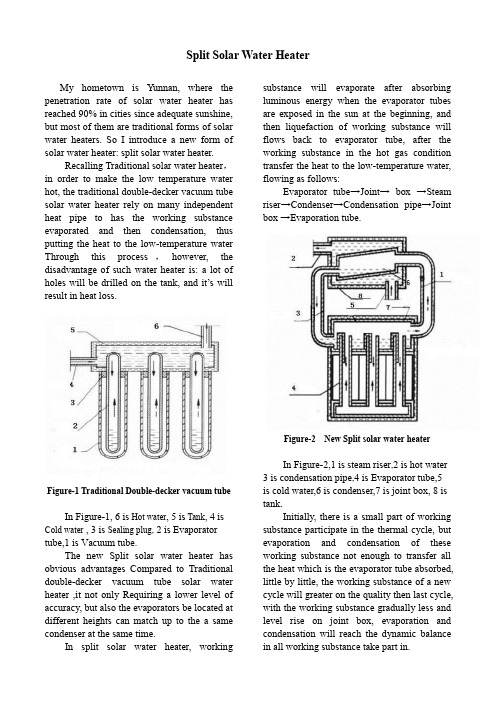
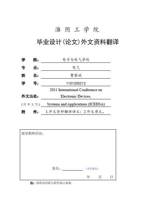
Split Solar Water HeaterMy hometown is Yunnan, where the penetration rate of solar water heater has reached 90% in cities since adequate sunshine, but most of them are traditional forms of solar water heaters. So I introduce a new form of solar water heater: split solar water heater.Recalling Traditional solar water heater , in order to make the low temperature water hot, the traditional double-decker vacuum tube solar water heater rely on many independent heat pipe to has the working substance evaporated and then condensation, thus putting the heat to the low-temperature water Through this process ,however, the disadvantage of such water heater is: a lot of holes will be drilled on the tank, and it’s willresult in heat loss.Figure-1 Traditional Double-decker vacuum tubeIn Figure-1, 6 is Hot water , 5 is Tank , 4 is Cold water , 3 is Sealing plug, 2 is Evaporator tube,1 is Vacuum tube.The new Split solar water heater has obvious advantages Compared to Traditional double-decker vacuum tube solar water heater ,it not only Requiring a lower level of accuracy, but also the evaporators be located at different heights can match up to the a same condenser at the same time.In split solar water heater, workingsubstance will evaporate after absorbing luminous energy when the evaporator tubes are exposed in the sun at the beginning, and then liquefaction of working substance will flows back to evaporator tube, after the working substance in the hot gas condition transfer the heat to the low-temperature water, flowing as follows:Evaporator tube→Joint→ box →Steam riser→Condenser→Condensation pipe→Joint box→Evapo ration tube.Figure-2 New Split solar water heaterIn Figure-2,1 is steam riser ,2 is hot water 3 is condensation pipe ,4 is Evaporator tube,5 is cold water,6 is condenser,7 is joint box, 8 is tank.Initially, there is a small part of working substance participate in the thermal cycle, but evaporation and condensation of these working substance not enough to transfer all the heat which is the evaporator tube absorbed, little by little, the working substance of a new cycle will greater on the quality then last cycle, with the working substance gradually less and level rise on joint box, evaporation and condensation will reach the dynamic balance in all working substance take part in.Because the tank will permit to be placedin interior, this will efficaciously reduce heat dissipation, and only 4 holes on the tank, will also reduce heat loss. Just in the meantime,the split soar water heater can add electric heating system or gas heating system so that users can also enjoy the warm water even in the rainy day.Improving program:Not only in view of the solar power panels installed on the housing is not pleasing to tour eyes and affect the interior lighting, but also difficult to repair. Proposed small-scale community or school set up unified solar power hot water supply station, put absorb solar power panels and water tanks are concentrated in one place, setting a unified water supply center, can make full use of resources and convenient the life of Community residents.。

太阳能热水器的研发及其应用研究一、引言太阳能热水器是利用太阳能进行水加热的装置,具有环保、节能等优势。
随着环保意识的逐渐增强,太阳能热水器在我国得到了广泛应用。
本文将从太阳能热水器的研发和应用两个方面进行探讨。
二、太阳能热水器的研发1、研发背景太阳能热水器的研发与应用始于上世纪70年代,受到社会、政府、学术机构等各方面的关注和支持。
随着技术的不断更新和进步,太阳能热水器的研发也得到了飞速的发展。
2、研发成果太阳能热水器的研发成果包括太阳能集热器、蓄热系统、控制系统等。
太阳能集热器是太阳能热水器的核心部件,其主要组成包括吸热板、集热管、保温材料等。
目前,太阳能集热器的结构形式有真空管式、平板式、膜式等多种类型,不同类型的太阳能集热器各有特点。
3、研发难点太阳能热水器的研发过程中,存在技术难点,主要包括:低温抗冻、高温耐热、耐腐蚀等。
研制太阳能热水器需要注意各种原材料是否符合质量标准,是否能抵御自然灾害和年久失修的影响等。
因此,在太阳能热水器的研发过程中,需要不断更新技术手段和加强质量控制。
三、太阳能热水器的应用研究1、应用背景太阳能热水器的应用范畴广泛,主要应用于家庭、学校、医院、旅馆等场所。
在我国,太阳能热水器普及率较高,但在生产和使用过程中,各种问题也随之出现。
2、应用现状太阳能热水器的普及率和使用率在我国居于领先地位,但相对于传统能源,太阳能热水器在使用过程中也存在着一定的弊端。
主要表现在:太阳能集热器采光不足、保温材料失效、水垢过多等问题。
而随着技术不断更新,太阳能热水器的使用寿命和效率也逐渐得到提高。
3、应用发展太阳能热水器的应用和普及是一个长期的过程,需要政府和企业的支持与投资。
除此之外,太阳能热水器的普及还需要消费者的认可和接受,这需要推广和普及,提高消费者的环保意识。
四、结论太阳能热水器是未来可持续发展的重要环节之一,其在环保和节能方面具有广泛的应用前景。
同时,在太阳能热水器的研发和应用中,还存在着一定的难题和问题,可通过技术手段的不断更新和质量控制的加强来解决。

本科毕业设计 (论文)某酒店太阳能热水系统设计A Design of Solar Hot Systems for A Hotle学院:专业班级:学生姓名:学号:指导教师:2014年5月毕业设计(论文)原创性声明和使用授权说明原创性声明本人郑重承诺:所呈交的毕业设计(论文),是我个人在指导教师的指导下进行的研究工作及取得的成果。
尽我所知,除文中特别加以标注和致谢的地方外,不包含其他人或组织已经发表或公布过的研究成果,也不包含我为获得及其它教育机构的学位或学历而使用过的材料。
对本研究提供过帮助和做出过贡献的个人或集体,均已在文中作了明确的说明并表示了谢意。
作者签名:日期:指导教师签名:日期:使用授权说明本人完全了解大学关于收集、保存、使用毕业设计(论文)的规定,即:按照学校要求提交毕业设计(论文)的印刷本和电子版本;学校有权保存毕业设计(论文)的印刷本和电子版,并提供目录检索与阅览服务;学校可以采用影印、缩印、数字化或其它复制手段保存论文;在不以赢利为目的前提下,学校可以公布论文的部分或全部内容。
作者签名:日期:学位论文原创性声明本人郑重声明:所呈交的论文是本人在导师的指导下独立进行研究所取得的研究成果。
除了文中特别加以标注引用的内容外,本论文不包含任何其他个人或集体已经发表或撰写的成果作品。
对本文的研究做出重要贡献的个人和集体,均已在文中以明确方式标明。
本人完全意识到本声明的法律后果由本人承担。
作者签名:日期:年月日学位论文版权使用授权书本学位论文作者完全了解学校有关保留、使用学位论文的规定,同意学校保留并向国家有关部门或机构送交论文的复印件和电子版,允许论文被查阅和借阅。
本人授权大学可以将本学位论文的全部或部分内容编入有关数据库进行检索,可以采用影印、缩印或扫描等复制手段保存和汇编本学位论文。
涉密论文按学校规定处理。
作者签名:日期:年月日导师签名:日期:年月日目录1 绪论 (1)2 能源与太阳能 (1)2.1 能源及其分类 (1)2.2 能源危机 (2)2.3 太阳能及其特点 (2)2.4 太阳能利用发展简史 (3)2.5 太阳能利用形式 (4)3 太阳能热水系统 (4)3.1 太阳能热水系统分类 (4)3.2 太阳能热水系统构成 (5)3.3 太阳能热水系统原理 (6)4 酒店太阳能热水系统设计 (7)4.1 太阳能热水系统设计原则 (7)4.2 太阳能热水系统设计依据 (7)4.3 系统设计之前的了解的问题 (7)4.4 太阳能热水系统设计计算 (7)4.5 贮水箱设计 (14)4.6 辅助热源设计 (15)4.7 管网设计 (18)4.8 水泵设计 (21)4.9 系统控制 (23)4.10 附件的设计 (26)4.11 保温设计 (26)5 系统主要设备、部件清单及报价 (27)6 系统设计图纸 (27)结论 (28)致谢 (29)参考文献 (30)附录 (31)附表清单:表1 太阳能热水系统分类 (5)表2 不同地区太阳能保证率的选值范围 (10)表3 不同建筑α系数值 (18)表4 管径与流速关系 (19)表5 热水回水管管径确定 (20)表 6 系统元器件统计表 (27)1 绪论近年来,随着人类经济的高速发展,人们对能源的需求越来越大,地球上的各类自然资源被飞速的消耗着。

Solar Tracking SystemSolar tracking system is thermal and photovoltaic power generation process, the most optimal use of sunlight, to improve the photoelectric conversion efficiency of the mechanical system and the electronic control unit, comprising: a motor (DC, stepper, servo, planetarygear motor, motor plunger ), worm, sensor systems and so on.In the solar photovoltaic applications: Keep solar panels facing the sun at any time, so that at any time the vertical rays of sunlight illuminated solar panels power plant, the use of solar tracking system can significantly improve the power generation efficiency of solar photovoltaic modules.Due to the Earth's rotation, a fixed location relative to a particular solar photovoltaic systems, four seasons a year, every day the rising sun, the sun's illumination angle changes all the time, effectively guaranteed solar panels can always being right Solar power generation efficiency will reach the best condition. Currently the world's universal solar tracking systems need to put such information to calculate latitude and longitude points for each day of the year at different times where the angle of the sun will be a year in the position of the sun every moment stores PLC, microcontroller or computer software in calculating the fixed locations have to rely on the position of the sun at each moment in order to achievetracking. Uses the theory of computer data, needs to Earth coordinates regional data and settings, once installed, it inconvenient to move or dismantle, finished on each move must be recalculated parameter setting data and adjust various parameters; principle, circuit, technology, equipment is very complexMiscellaneous, non-professionals can not easily operate. Hebei, a solar photovoltaic power generation companies exclusively developed with world-leading level, do not calculate the position of the sun around the data, free software, not afraid cloudy, thunderstorms, cloudy and other inclement weather, has been the default system device saver, dustproof effect strong wind resistance, easy to use, low cost, anytime, anywhere on your mobile device can accurately track the sun's intelligent solar tracking system. The solar tracking system in the company's first-generation tracker technology based on integrated use of a variety of environments around the situation, the solar tracking system was fully upgraded and improved, so that the solar tracking system has become all-weather, full-featured, Super energy saving, intelligent solar tracking system. The solar tracking system has a normal (good weather conditions) under the Japanese track status and harsh climatic conditions and the state of the system of self-protection equipment to protect themselves from the normal state automatically and quickly converted to the Japanese track three cases.Adds a GPS positioning system, the solar tracking system is the first fully computer software without spatial orientation of the sun tracker, a leading international level, it is possible without geographical, weather conditions and external conditions, can be -50 ℃to 70 ℃ambient temperature range of normal use; tracking precision can reach ± 0.001 °, to maximize solar tracking accuracy, the perfect track to achieve timely and maximize solar energy utilization. The solar tracking system can be widely used in various types of equipment requires the use of solar tracking where the solar tracking system, affordable, stable performance, reasonable structure, precise tracking, easy to use. The installation of a solar tracking system solar power systems installed in high-speed car, train, and communications emergency vehicles, special military vehicles, warships or ships, and whether the system is running to where and how to turn around, turn the solar tracking system equipment requirements to ensure the site is tracking the sun! The solar tracking control technology with our own intellectual property rights belonging to national invention patent product, patent application number: 200610146201.8, has mass production.The solar tracking system has four operating state:1 Normal (good weather conditions) under the Japanese track status;2 intermittent tracking. If there is a period of time of day is cloudy or cloudy or inclement weather, the system will be screened out asunsuitable track, the entire system will be in a suspended state. Until light and track conditions are suitable, the system will be a fast-track instruction, so that roughly aligned with the sun tracker. , The program will conduct another set of signal acquisition and processing, complete the fine tracking;3 automatic back. Sunset, the system will automatically enter the sleep state, and automatically return to the position of the rising sun. The next day and then automatically enters a new round of running.4 inclement weather state protection: When the environment is not suitable for such factors as wind or precipitation system work, tracker will automatically stop working, and the whole big system receiving surface state and the ground plane parallel or vertical to prevent the system being to destruction.The solar tracking system main application areas:(1) a flat photovoltaic photovoltaic field and 500 times the CPV systems;(2) the field of solar thermal parabolic track (such as solar cookers, solar heating temperature, solar thermal and chemical);(3) solar trough collector;(4) solar thermal power tower and so on.太阳能跟踪系统太阳能跟踪系统是光热和光伏发电过程中,最优化太阳光使用,达到提高光电转换效率的机械及电控单元系统,包括:电机(直流、步进、伺服、行星减速电机、推杆电机等)、涡轮蜗杆、传感器系统等等。

太阳能的应用和发展英语作文English Response:Solar Energy: Application and Development.Solar energy, in its essence, is a boundless source of power derived from the sun. Its applications and development have gained significant traction in recentyears due to increasing concerns about climate change and the finite nature of fossil fuels. Let's delve into the various aspects of solar energy utilization and its promising future.Applications:One of the most common applications of solar energy isin generating electricity through photovoltaic (PV) systems. These systems consist of solar panels that convert sunlight directly into electricity. They can be installed onrooftops of residential buildings, commercialestablishments, and even in large solar farms. For instance, my friend Sarah recently had solar panels installed on her roof. Now, she not only saves money on her electricitybills but also contributes to reducing carbon emissions.Solar energy is also widely used for heating purposes, especially in solar water heaters. These systems usesunlight to heat water for domestic, commercial, orindustrial use. I remember visiting a resort last summer where they had solar water heaters installed in their swimming pools. It was fascinating to learn how theyutilized solar energy to maintain the perfect temperaturefor their guests' comfort.Furthermore, solar energy plays a crucial role in providing lighting solutions in remote or off-grid areas through solar-powered LED lights. For example, in rural villages where access to electricity is limited, solarstreet lights have been installed to illuminate pathwaysand enhance safety during the night. My cousin volunteersfor a non-profit organization that installs such lights in underserved communities, making a tangible difference inpeople's lives.Development:The development of solar energy technology has been remarkable, with ongoing advancements aimed at improving efficiency and reducing costs. Innovations like thin-film solar cells, concentrated solar power (CSP) systems, and solar tracking mechanisms have enhanced the effectiveness of harnessing solar energy. Additionally, research in materials science and nanotechnology holds promise for further enhancing solar cell performance.Moreover, policy support and incentives have played a pivotal role in driving the growth of solar energy. Many governments offer tax credits, rebates, and feed-in tariffs to encourage the adoption of solar power systems. In my country, the government recently announced a subsidy program for homeowners who install solar panels, making it more affordable for ordinary citizens to embrace clean energy solutions.Future Prospects:Looking ahead, the future of solar energy appears exceedingly bright. As technology continues to advance and economies of scale are realized, solar power is expected to become even more competitive with conventional energy sources. With increasing public awareness and commitment to sustainability, the demand for solar energy is likely to soar.Furthermore, integration with energy storage systems such as batteries is poised to revolutionize the solar energy landscape. This would enable greater gridflexibility and reliability, allowing solar power to meet demand even when the sun isn't shining. Imagine a future where households rely predominantly on solar energy for their electricity needs, with excess power stored for use during cloudy days or at night.In conclusion, solar energy's applications are diverse and its development is rapidly evolving. Through technological innovation, supportive policies, and growingpublic acceptance, solar power is positioned to play a pivotal role in shaping a cleaner and more sustainable energy future.中文回答:太阳能,应用与发展。
太阳能热泵热水系统摘要:近年来,随着我国经济的不断提高,城乡建设迅速发展,能源的需求及耗费量巨额增加,充分利用和开发可再生能源——太阳能、空气热能等新能源势在必行。
本文提出了一种太阳能-热泵中央热水系统形式,介绍了其工作原理和各组成部分的设计要求以及工程应用实例。
是一种实用的环保节能技术,具有一定的推广应用价值。
关键词:太阳能热泵辅助加热热水系统Abstract: in recent years, as the economy continues to improve, urban and rural construction and rapid development, energy demand and consumption huge increase, make full use of and the development of renewable energy sources such as solar energy, air heat energy, new energy is imperative. This paper puts forward a kind of solar energy heat pump hot water system of the central form, this paper introduces the working principle and the design requirements of each part and examples of engineering application. Is a kind of practical environmental protection and energy saving technology, has some of the application value.Keywords: solar energy heat pump hot water system auxiliary heating一.太阳能辅助加热空气源热泵机组工作原理我们先了解气源热泵的热效率:气源热泵通过压缩机做功,转换环境中大气的热量把水加热,热泵的热效率可用下式计算:η=Q+λW/W式中Q——工质气化是吸收环境中的热量;W——压缩机加压所做的功;λ——机械功转化为内能的效率。
中英文资料对照外文翻译文献综述Design of a Lead-Acid Battery Charging and Protecting IC in Photovoltaic System1.IntroductionSolar energy as an inexhaustible, inexhaustible source of energy more and more attention. Solar power has become popular in many countries and regions, solar lighting has also been put into use in many cities in China. As a key part of the solar lighting, battery charging and protection is particularly important. Sealed maintenance-free lead-acid battery has a sealed, leak-free, pollution-free, maintenance-free, low-cost, reliable power supply during the entire life of the battery voltage is stable and no maintenance, the need for uninterrupted for the various types of has wide application in power electronic equipment, and portable instrumentation. Appropriate float voltage, in normal use (to prevent over-discharge, overcharge, over-current), maintenance-free lead-acid battery float life of up to 12 ~ 16 years float voltage deviation of 5% shorten the life of 1/2. Thus, the charge has a major impact on this type of battery life. Photovoltaic, battery does not need regular maintenance, the correct charge and reasonable protection, can effectively extend battery life. Charging and protection IC is the separation of the occupied area and the peripheral circuit complexity. Currently, the market has not yet real, charged with the protection function is integrated on a single chip. For this problem, design a set of battery charging and protection functions in one IC is very necessary.2.System design and considerationsThe system mainly includes two parts: the battery charger module and the protection module. Of great significance for the battery as standby power use of the occasion, It can ensure that the external power supply to the battery-powered, but also in the battery overcharge, over-current and an external power supply is disconnected the battery is to put the state to provide protection, the charge and protection rolled into one to make the circuit to simplify and reduce valuable product waste of resources. Figure 1 is a specific application of this Ic in the photovoltaic powergeneration system, but also the source of this design.Figure1 Photovoltaic circuit system block diagramMaintenance-free lead-acid battery life is usually the cycle life and float life factors affecting the life of the battery charge rate, discharge rate, and float voltage. Some manufacturers said that if the overcharge protection circuit, the charging rate can be achieved even more than 2C (C is the rated capacity of the battery), battery manufacturers recommend charging rate of C/20 ~ C/3. Battery voltage and temperature, the temperature is increased by 1 °C, single cell battery voltage drops 4 mV , negative temperature coefficient of -4 mV / ° C means that the battery float voltage. Ordinary charger for the best working condition at 25 °C; charge less than the ambient temperature of 0 °C; at 45 °C may shorten the battery life due to severe overcharge. To make the battery to extend the working life, have a certain understanding and analysis of the working status of the battery, in order to achieve the purpose of protection of the battery. Battery, there are four states: normal state, over-current state over the state of charge, over discharge state. However, due to the impact of the different discharge current over-capacity and lifetime of the battery is not the same, so the battery over discharge current detection should be treated separately. When the battery is charging the state a long time, would severely reduce the capacity of the battery and shorten battery life. When the battery is the time of discharge status exceeds the allotted time, the battery, the battery voltage is too low may not be able to recharge, making the battery life is lower.Based on the above, the charge on the life of maintenance-free lead-acid batteries have a significant impact, while the battery is always in good working condition, battery protection circuit must be able to detect the normal working condition of the battery and make the action the battery can never normal working state back to normal operation, in order to achieve the protection of the battery.3.Units modular design3.1The charging module Chip, charging module block diagram shown in Figure 2. The circuitry includes solar battery array Charge controller controller Discharge controller DC load accumulatorcurrent limiting, current sensing comparator, reference voltage source, under-voltage detection circuit, voltage sampling circuit and logic control circuit.Figure2 Charging module block diagramThe module contains a stand-alone limiting amplifier and voltage control circuit, it can control off-chip drive, 20 ~30 mA, provided by the drive output current can directly drive an external series of adjustment tube, so as to adjust the charger output voltage and current . V oltage and current detection comparator detects the battery charge status, and control the state of the input signal of the logic circuit. When the battery voltage or current is too low, the charge to start the comparator control the charging. Appliances into the trickle charge state when the cut-off of the drive, the comparator can output about 20 mA into the trickle charge current. Thus, when the battery short-circuit or reverse, the charger can only charge a small current, to avoid damage to the battery charging current is too large. This module constitutes a charging circuit charging process is divided into two charging status: high-current constant-current charge state, high-voltage charge status and low-voltage constant voltage floating state. The charging process from the constant current charging status, the constant charging current of the charger output in this state. And the charger continuously monitors the voltage across the battery pack, the battery power has been restored to 70% to 90% of the released capacity when the battery voltage reaches the switching voltage to charge conversion voltage Vsam charger moves to the state of charge. In this state, the charger output voltage is increased to overcharge pressure driverV oltage amplifierV oltage sampling comparatorStart amplifier State level control Charging indicator Logical module Undervoltage detection circuit R- powerCurrent sampling comparator Limiting amplifier Power indicatorV oc is due to the charger output voltage remains constant, so the charging current is a continuous decline. Current down to charge and suspend the current Ioct, the battery capacity has reached 100% of rated capacity, the charger output voltage drops to a lower float voltage VF.3.2 Protection ModuleChip block diagram of the internal protection circuit shown in Figure 3. The circuit includes control logic circuit, sampling circuit, overcharge detection circuit, over-discharge detection comparator, overcurrent detection comparator, load short-circuit detection circuit, level-shifting circuit and reference circuit (BGR).Figure3 Block diagram of battery protectionThis module constitutes a protection circuit shown in Figure 4. Under the chip supply voltage within the normal scope of work, and the VM pin voltage at the overcurrent detection voltage, the battery is in normal operation, the charge and discharge control of the chip high power end of the CO and DO are level, when the chip is in normal working mode. Larger when the battery discharge current will cause voltage rise of the VM pin at the VM pin voltage at above the current detection voltage Viov, then the battery is the current status, if this state to maintain the tiov overcurrent delay time, the chip ban on battery discharge, then the charge to control the end of CO is high, the discharge control side DO is low, the chip is in the current mode, general in order to play on the battery safer and more reasonable protection, the chip will battery over-discharge current to take over the discharge current delay time protection. The general rule is that the over-discharge current is larger, over the Sampling circuitOver discharge detection comparator Control logic circuitLevel conversion circuit Overcharge detection comparator Over-current detection comparator2 Over-current detection comparator1Over-current detection circuitLoad short detection circuitshorter the discharge current delay time. Above Overcharge detection voltage, the chip supply voltage (Vdd> Vcu), the battery is in overcharge state, this state is to maintain the corresponding overcharge delay time tcu chip will be prohibited from charging the battery, then discharge control end DO is high, and charging control terminal CO is low, the chip is in charging mode. When the supply voltage of the chip under the overdischarge detection voltage (Vdd <Vdl,), then the battery is discharged state, this state remains the overdischarge delay time tdl chip will be prohibited to discharge the battery at this time The charge control side CO is high, while the discharge control terminal DO is low, the chip is in discharge mode.ProtectionmoduleFigure4 Protection circuit application schematic diagram4.Circuit DesignTwo charge protection module structure diagram, the circuit can be divided into four parts: the power detection circuit (under-voltage detection circuit), part of the bias circuit (sampling circuit, the reference circuit and bias circuit), the comparator (including the overcharge detection /overdischarge detection comparator, over-current detection and load short-circuit detection circuit) and the logic control part.This paper describes the under-voltage detection circuit (Figure 5), and gives the bandgap reference circuit (Figure 6).Figure5 Under-voltage detection circuitFigure6 A reference power supply circuit diagramBattery charging, voltage stability is particularly important, undervoltage, overvoltage protection is essential, therefore integrated overvoltage, undervoltage protection circuit inside the chip, to improve power supply reliability and security. And protection circuit design should be simple, practical, here designed a CMOS process, the undervoltage protection circuit, this simple circuit structure, process and easy to implement and can be used as high-voltage power integrated circuits and other power protection circuit.Undervoltage protection circuit schematic shown in Figure 5, a total of five components: the bias circuit, reference voltage, the voltage divider circuit, differential amplifier, the output circuit. The circuit supply voltage is 10V; the M0, M1, M2, R0 is the offset portion of the circuit to provide bias to the post-stage circuit, the resistance, Ro, determine the circuit's operating point, the M0, M1, M2 form a current mirror; R1 M14 is the feedback loop of the undervoltage signal; the rest of the M3, M4 and M5, M6, M7, M8, M9, M10, M11, M12, M13, M14, composed of four amplification comparator; M15, DO, a reference voltage, the comparator input with the inverting Biasing circuit Reference circuit Bleeder circuit difference amplifier Output circuitAmplifierAmplifierinput is fixed (V+), partial pressure of the resistance R1, R2, R3, the input to the inverting input of the comparator, when the normal working of the power supply voltage, the inverting terminal of the voltage detection is lost to the inverting terminal voltage of the comparator is greater than V+. Comparator output is low, M14 cutoff, feedback circuit does not work; undervoltage occurs, the voltage divider of R1, R2, R3, reaction is more sensitive, lost to the inverting input voltage is less than V when the resistor divider, the comparator the output voltage is high, this signal will be M14 open, the voltage across R into M at both ends of the saturation voltage close to 0V, thereby further driving down the R1> R2, the partial pressure of the output voltage, the formation of the undervoltage positive feedback. Output, undervoltage lockout, and plays a protective role.5. Simulation results and analysisThe design of the circuit in CSMC 0.6 μm in digital CMOS process simulation and analysis of the circuit. In the overall simulation of the circuit, the main observation is that the protection module on the battery charge and discharge process by monitoring Vdd potential and Vm potential leaving chip CO side and DO-side changes accordingly. The simulation waveform diagram shown in Figure 7, the overall protection module with the battery voltage changes from the usual mode conversion into overcharge mode, and then return to normal working mode, and then into the discharge mode, and finally back to normal working mode. As the design in the early stages of the various parameters to be optimized, but to provide a preliminary simulation results.Figure7 Overvoltage and under-voltage protection circuit simulation waveform6.ConclusionDesigned a set of battery charging and protection functions in one IC. This design not only can reduce the product, they can reduce the peripheral circuit components. The circuit uses the low-power design. This project is underway to design optimization stage, a complete simulation can not meet the requirements, but also need to optimize the design of each module circuit.光伏系统中蓄电池的充电保护IC电路设计1.引言太阳能作为一种取之不尽、用之不竭的能源越来越受到重视。
附录A 外文文献译文有效地发展太阳能热发电技术在中国是一个巨大的挑战。
在该文件中的一个抛物面槽式太阳能集热器实验平台系统(抛物槽式太阳能集热器系统)的开发热发电,以及抛物槽式太阳能集热器系统性能进行了实验研究与合成油为散发有机热载体(导热油)。
该太阳能集热器与太阳通量的变化与流速的导热油效率鉴定。
该集热效率抛物槽式太阳能集热器系统可以在40%-60%之间。
有人还发现,存在着一个为导热油温度响应太阳能通量,而在设计中发挥了重要作用抛物槽式太阳能集热器系统指定的延迟。
对集热效率热损失的影响进行了研究,这对于用180℃之间的收藏家温度和环境温度的温差接收约220瓦/米,大约相当于在总数的10%,太阳能事件收藏家。
这些令人鼓舞的结果可为开发抛物面槽式太阳能在中国火电厂的基本数据。
简介抛物槽式太阳能热发电技术已经取得了三个太阳能热发电技术的广泛普及。
大型抛物面槽式收藏家可以提供热能,可用于生产蒸汽涡轮发电机一朗肯蒸汽。
经常采用的是抛物槽式太阳能集热器系统蒸汽发电由于其高集电极的效率在中间温度(约300℃)。
作者在抛物槽式太阳能集热器系统性能起着重要作用的抛物面槽式太阳能电厂,它直接决定了投资成本。
优化和改进的抛物槽式太阳能集热器系统性能,许多调查已经进行了自太阳能资源。
在中国丰富,尤其是在如青海省,西藏,新疆地区,西部,抛物线槽式太阳能热发电技术已受到广泛关注最近。
实验平台和程序为了研究太阳能热发电,实验平台的开发抛物槽式太阳能集热器系统。
实验平台主要由四部分组成:太阳能集热器,换热流体(导热油)循环,冷却水循环,测量系统.找个实验平台流程图使用合成油作为流通导热油。
该导热油不仅可以流通之间的油箱和水箱电热水器,还可以通过太阳能接收流动单位。
在一个典型的实验中,首先被送入导热油电加热器坦克一泵,加热到一定温度。
然后,导热油,抽到太阳能接收装置吸收太阳能。
加热后的导热油离开接收机是由冷却的冷却水热交换器,最后回流到油箱,循环完成的。
1 主题内容与适用范围本标准规定了太阳能热利用中一部分关于天文与辐射的术语。
本标准适用于太阳能热利用中对太阳辐射的研究与测量。
2 引用标准GB 3102.6 光及有关电磁辐射的量和单位GB 4270 热工图形符号与文字代号3 天文3.1 天球celestial sphere为研究天体的位置和运动而辅设的一个半径为无限长的假想球体。
其中心按需要可设在观测点、地心、日心或银心等。
天体的位置即指沿天球中心至该天体方向在球面上的投影。
3.2 天轴celestial axis天球的自转轴。
它通过天球中心并平行于地球自转轴。
3.3 天极celestial pole天轴与天球相交的两个交点的统称。
3.4 北天极celestial north pole北半天球上的天极。
3.5 南天极celestial south pole南半天球上的天极。
3.6 天顶zenith观测点铅垂线向上延长与天球相交的交点。
3.7 天底nadir观测点铅垂线向下延长与天球相交的交点。
3.8 天赤道celestial equator通过天球中心并垂直于天轴的平面与天球相交的大圆。
3.9 天球子午圈celestial meridian天球上通过天顶和天极的大圆。
同义词天球子午线3.10 时圈hour circle天球上通过两天极的任一大圆。
同义词赤经圈right ascension circle3.11 地平面horizontal plane地球表面观测点以铅垂线为法线的切平面。
3.12 地平圈horizontal circle通过天球中心并垂直于天顶-天底连线的平面与天球相交的大圆。
同义词地平线horizon3.13 地平经圈vertical circle天球上通过天顶和天底的任一大圆。
3.14 角距离angular distance天球大圆上任意两点所对应的圆心角。
3.15 天球坐标系celestial coordinate system为确定天体在天球上的投影位置和运动而引入的球面坐标系。
附录SOLAR WATER HEATING BACKGROUND Using the sun’s energy to heat water is not a new idea. More than one hundred years ago, black painted water tanks were used as simple solar water heaters in a number of countries. Solar water heating (SWH) technology has greatly improved during the past century. Today there are more than 30 million m2 of solar collectors installed around the globe. Hundreds of thousands of modern solar water heaters, such as the one shown in Figure 1, are in use in countries such as China, India, Germany, Japan, Australia and Greece. In fact, in some countries the law actually requires that solar water heaters be installed with any new residential construction project (Israel for example).Figure1: Evacuated Tube Solar Collector in Tibet, China In addition to the energy cost savings on water heating, there are several other benefits derived from using the sun’s energy to heat water. Most solar water heaters come with an additional water tank, which feeds the conventional hot water tank. Users benefit from the larger hot water storage capacity and the reduced likelihood of running out of hot water. Some solar water heaters do not require electricity to operate. For these systems, hot water supply is secure from power outages, as long as there is sufficient sunlight to operate the system. Solar water heating systems can also be used to directly heat swimming pool water, with the added benefit of extending the swimming season for outdoor pool applications.◆Solar Water Heating Application MarketsSolar water heating markets can be classified based upon the end-use application of the technology. The most common solar water heating application markets are service hot water and swimming pools.◆Service hot waterThere are a number of service hot water applications. The most common application is the use of domestic hot water systems (DHWS), generally sold as “off-the-shelf” or standard kits as depicted in Figure 2.Figure2: Solar Domestic Hot Water System in AustraliaSwimming poolsThe water temperature in swimming pools can also be regulated using solar water heating systems, extending the swimming pool season and saving on the conventional energy costs. The basic principle of these systems is the same as with solar service hot water systems, with the difference that the pool itself acts as the thermal storage. For outdoor pools, a properly sized solar water heater can replace a conventional heater; the pool water is directly pumped through the solar collectors by the existing filtration system.Swimming pool applications can range in size from small summer only outdoor pools, such as the one shown at a home in Figure 3, to large Olympic size indoor swimming pools that operate 12 months a year.Figure 3: Unglazed Solar Collector Pool Heating System in Canada◆Description of Solar Water Heating SystemsSolar water heating systems use solar collectors and a liquid handling unit to transfer heat to the load, generally via a storage tank. The liquid handling unit includes the pump (used to circulate the working fluid from the collectors to the storage tank) and control and safety equipment. When properly designed, solar water heaters can work when the outside temperature is well below freezing and they are also protected from overheating on hot, sunny days. Many systems also have a back-up heater to ensure that all of a consumer’s hot water needs are met even when there is insufficient sunshine. Solar water heaters perform three basic operations as shown in Figure 4:Collection: Solar radiation is “captured” by a solar collectorTransfer: Circulating liquid transfer this energy to a storage tank;circulation can be natural (thermo siphon systems) or forced, using a circulator (low-head pump); andStorage: Hot water is stored until it is needed at a later time in a mechanical room, or on the roof in the case of a thermo siphon system.Figure 4: System Schematic for Typical Solar Domestic Water Heater◆Solar collectorsSolar energy (solar radiation) is coll ected by the solar collector’s absorber plates. Selective coatings are often applied to the absorber plates to improve the overall collection efficiency. A thermal fluid absorbs the energy collected.There are several types of solar collectors to heat liquids. Selection of a solar collector type will depend on the temperature of the application being considered and the intended season of use (or climate). The most common solar collector types are:unglazed liquid flat-plate collectors; glazed liquid flat-plate collectors; and evacuated tube solar collectors.◆Unglazed liquid lat-plate collectorsUnglazed liquid flat-plate collectors, as depicted in Figure 5, are usually made of a black polymer. They do not normally have a selective coating and do not include a frame and insulation at the back; they are usually simply laid on a roof or on a wooden support. These low-cost collectors are good at capturing the energy from the sun, but thermal losses to the environment increase rapidly with water temperature particularly in windy locations. As a result, unglazed collectors are commonly used for applications requiring energy delivery at low temperatures (pool heating, make-up water in fish farms, process heating applications, etc.); in colder climates they are typically only operated in the summer season due to the high thermal losses of the collector.Figure 5: System Schematic for Unglazed Flat-Plate Solar Collector◆Balance of systemsIn addition to the solar collector, a solar water heating system typically includes the following “balance of system components”1. Solar collector array support structure, as depicted in the Figure 6;Figure 6: Solar Array Support Structure2. Hot water storage tank (not required in swimming pool applications and in some large commercial or industrial applications when there is a continuous service hot water low).3. Liquid handling unit, which includes a pump required to transfer the fluid from the solar collector to the hot water storage tank (except in thermo siphon systems where circulation is natural, and outdoor swimming pool applications where the existing filtration system pump is generally used) .it also includes valves, strainers, and a thermal expansion tank.4. Controller, which activates the circulator only when usable heat is available from the solar collectors (not required for thermo siphon systems or if a photovoltaic-Powered circulator is used).5. Freeze protection, required for use during cold weather operation, typically through the use in the solar loop of a special antifreeze heat transfer fluid with a low-toxicity. The solar collector fluid is separated from the hot water in the storage tank by a heat exchanger; and.6. Other features, mainly relating to safety, such as overheating protection, seasonal systems freeze protection or prevention against restart of a large system after a stagnation period. Typically, an existing conventional water heating system is used for back-up to the solar water heating system, with the exception that a back-up system is normally not required for most outdoor swimming pool applications.太阳能热水系统研究背景利用太阳能来加热水的并不是一个新的想法。